EP3791024B1 - Verfahren zum einsetzen eines pfahls im meeresboden - Google Patents
Verfahren zum einsetzen eines pfahls im meeresboden Download PDFInfo
- Publication number
- EP3791024B1 EP3791024B1 EP19724139.1A EP19724139A EP3791024B1 EP 3791024 B1 EP3791024 B1 EP 3791024B1 EP 19724139 A EP19724139 A EP 19724139A EP 3791024 B1 EP3791024 B1 EP 3791024B1
- Authority
- EP
- European Patent Office
- Prior art keywords
- lead
- pile
- foundation structure
- template
- existing foundation
- Prior art date
- Legal status (The legal status is an assumption and is not a legal conclusion. Google has not performed a legal analysis and makes no representation as to the accuracy of the status listed.)
- Active
Links
Images


Classifications
-
- E—FIXED CONSTRUCTIONS
- E02—HYDRAULIC ENGINEERING; FOUNDATIONS; SOIL SHIFTING
- E02D—FOUNDATIONS; EXCAVATIONS; EMBANKMENTS; UNDERGROUND OR UNDERWATER STRUCTURES
- E02D13/00—Accessories for placing or removing piles or bulkheads, e.g. noise attenuating chambers
- E02D13/04—Guide devices; Guide frames
-
- E—FIXED CONSTRUCTIONS
- E02—HYDRAULIC ENGINEERING; FOUNDATIONS; SOIL SHIFTING
- E02D—FOUNDATIONS; EXCAVATIONS; EMBANKMENTS; UNDERGROUND OR UNDERWATER STRUCTURES
- E02D13/00—Accessories for placing or removing piles or bulkheads, e.g. noise attenuating chambers
- E02D13/06—Accessories for placing or removing piles or bulkheads, e.g. noise attenuating chambers for observation while placing
-
- E—FIXED CONSTRUCTIONS
- E02—HYDRAULIC ENGINEERING; FOUNDATIONS; SOIL SHIFTING
- E02D—FOUNDATIONS; EXCAVATIONS; EMBANKMENTS; UNDERGROUND OR UNDERWATER STRUCTURES
- E02D13/00—Accessories for placing or removing piles or bulkheads, e.g. noise attenuating chambers
- E02D13/10—Follow-blocks of pile-drivers or like devices
-
- E—FIXED CONSTRUCTIONS
- E02—HYDRAULIC ENGINEERING; FOUNDATIONS; SOIL SHIFTING
- E02D—FOUNDATIONS; EXCAVATIONS; EMBANKMENTS; UNDERGROUND OR UNDERWATER STRUCTURES
- E02D5/00—Bulkheads, piles, or other structural elements specially adapted to foundation engineering
- E02D5/02—Sheet piles or sheet pile bulkheads
- E02D5/03—Prefabricated parts, e.g. composite sheet piles
- E02D5/04—Prefabricated parts, e.g. composite sheet piles made of steel
- E02D5/06—Fitted piles or other elements specially adapted for closing gaps between two sheet piles or between two walls of sheet piles
-
- E—FIXED CONSTRUCTIONS
- E02—HYDRAULIC ENGINEERING; FOUNDATIONS; SOIL SHIFTING
- E02D—FOUNDATIONS; EXCAVATIONS; EMBANKMENTS; UNDERGROUND OR UNDERWATER STRUCTURES
- E02D5/00—Bulkheads, piles, or other structural elements specially adapted to foundation engineering
- E02D5/02—Sheet piles or sheet pile bulkheads
- E02D5/03—Prefabricated parts, e.g. composite sheet piles
- E02D5/04—Prefabricated parts, e.g. composite sheet piles made of steel
- E02D5/08—Locking forms; Edge joints; Pile crossings; Branch pieces
-
- E—FIXED CONSTRUCTIONS
- E02—HYDRAULIC ENGINEERING; FOUNDATIONS; SOIL SHIFTING
- E02D—FOUNDATIONS; EXCAVATIONS; EMBANKMENTS; UNDERGROUND OR UNDERWATER STRUCTURES
- E02D7/00—Methods or apparatus for placing sheet pile bulkheads, piles, mouldpipes, or other moulds
- E02D7/02—Placing by driving
- E02D7/06—Power-driven drivers
- E02D7/14—Components for drivers inasmuch as not specially for a specific driver construction
- E02D7/16—Scaffolds or supports for drivers
-
- E—FIXED CONSTRUCTIONS
- E02—HYDRAULIC ENGINEERING; FOUNDATIONS; SOIL SHIFTING
- E02D—FOUNDATIONS; EXCAVATIONS; EMBANKMENTS; UNDERGROUND OR UNDERWATER STRUCTURES
- E02D2300/00—Materials
- E02D2300/0026—Metals
- E02D2300/0029—Steel; Iron
Definitions
- This invention relates to a method for construction of subsea foundation structures.
- This type of structure may be in the form of interlocking pipe piles, sheet piles, or combi-wall, or any other foundation type that requires high element-to-element precision.
- These elements may be driven using an impact hammer, a vibratory hammer, or drilled into place using a variety of tools.
- a common method for constructing a seabed wall structure is to use a temporary template structure or falsework to position and align the piles prior to and during installation.
- existing systems for the installation of subsea walls typically require the use of extensive falsework systems or use falsework that extends below the waterline to provide support for the piles during installation. Often divers are used in conjunction with falsework to confirm alignment and/or successful pile to pile interlock.
- An alternate method of installation is to extend the length of the pile to the waterline, which simplifies construction, and cut off the ends of the piles once the installation is completed.
- Related construction methods can be found in US 2015/0218765 , which discloses a dock building apparatus and method of construction, US 7 585 136 , which discloses a method and equipment for making an impermeable diaphragm of secant piles, NL 1 033 368 C2 , and US 2011/170956 A1 .
- a further example of a construction method, where a foundation structure is driven into the sea bed together with the pile, is shown in EP 0 059 648 A .
- a number of limitations stem from the common methods for constructing a seabed wall structure.
- the construction rate is typically limited by the movement and setup time of the falsework;
- the cost of the falsework can be significant, depending on the pile geometry, water depth, and accuracy required;
- the installation must be carried out during the day time, or have a limited production rate at night; and
- the method that cuts off the ends of piles requires additional operations and material, which affects productivity and cost.
- a method of driving a pile into a seabed floor adjacent to an existing foundation structure comprises lowering a lead longitudinally oriented in a first direction toward the subsea floor; engaging a lead indexing foot of the lead with the existing foundation structure; and advancing the pile, along the lead, in the first direction into the subsea floor.
- the lead indexing foot allows the lead to align with the existing foundation structure. Because the lead is indexed with the existing foundation structure, it is possible to install the pile during times with low viability, for example, turbulent water or night.
- the method may further comprise inserting an interlock of the pile into an interlock of the existing foundation structure.
- the interlock ensures that the pile is properly aligned while the pile is being driven into the seabed floor.
- the method may further comprise determining whether the interlock of the pile has engaged the interlock of the adjacent existing foundation structure.
- Determining whether the respective interlocks are properly engaged prior to driving the pile into the seabed floor prevents damage to the pile, damage to the existing foundation structure, and improper placement of the pile.
- the method may further comprise attaching the lead to a template that is adapted to move in a second direction that is perpendicular to the first direction.
- Having a detachable template allows for the template to be moved concurrently with a pile being loaded into the lead.
- the method may further comprise adjusting the location of the lead by moving the template on at least one rail.
- the method may further comprise loading the pile onto the lead prior to the step of lowering the lead in the first direction.
- This method may be preferable, for example, while performing an installation in turbulent water so that the lead does not remain submerged for longer than required.
- the method may further comprise loading the pile onto the lead after the step of lowering the lead.
- This method may be preferable, for example, while performing an installation in placid water. This method reduces the instillation time because the entire lead can be adjusted contemporaneously with the template rather than be disconnected therefrom.
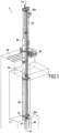
- Fig. 1 shows an apparatus for installing a seabed wall 1.
- the apparatus may include a lead 10, a template 20, rails 30, and a pile insertion device 40.
- the lead 10 comprises a long structural column that extends along an axis Y1 from a top end 10a to a bottom end 10b; the top end 10a is higher in elevation than the bottom end 10b.
- the lead 10 is a self-supporting system that uses integrated winches or crane winches to control the lead lift and elevation, the tool (e.g., pile driving hammer) lift and elevation, and the pile lift and elevation.
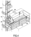
- the lead 10 is also equipped with an integrated slide 12 (shown in Fig. 4 ) which has a built-in interlock with the template 20 and a range of motion (vertical movement) suitable for a specific project.
- the hydraulic power that actuates the lead 10 integrated systems is provided by the supporting crane hydraulics or additional valve control system with a separate power pack unit or a combination of both (not shown).
- the lead 10 may have one or several gates 14 that are configured to position and align a foundation element, for example, a pile 50, relative to the lead 10.
- the gate 14 may include at least one gate arm 14a, that may be configured to swing between open and closed positions.
- the opening and closing of the gate arm 14a may be controlled by any suitable means, for example, hydraulics.
- the lead 10 further comprises a lead indexing foot 16 that extends along an axis Y2 that is laterally offset from the lead axis Y1.
- the lead indexing foot 16 is attached to the bottom end 10b of the lead.
- the lead indexing foot 16 may be joined to the bottom end 10b of the lead by, for example, welding or the lead indexing foot 16 may be fully integrated with the lead 10 as a unitary piece.
- the lead indexing foot 16 may form a tip portion 16a that is configured to align with an opening of an existing foundation structure 60, for example, a previously installed pile, group of piles, sheets, submerged supports laying on the seabed, etc.
- the lead indexing foot 16 further comprises a fitted portion 16b that is configured to at least partially contact an interior surface of the opening of the existing foundation structure 60.
- the lead indexing foot 16 further comprises a base portion 16c that is configured to interface with a top end 60a of the existing foundation structure 60.
- the radial distance r a from the axis Y2 of the tip portion 16a may be smaller than a radial distance r b from the Y2 axis than the fitted portion 16b.
- a surface that extends between the tip portion 16a and the fitted portion 16b of the lead indexing foot 16 may be tapered.
- the lead 10 may further comprise a second lead indexing foot 18 that is configured to align and interface with another portion of the existing foundation structure 60, for example, an adjoining previously installed pile.
- the second lead indexing foot 18 may extend along a third axis Y3 that is laterally offset from both the lead axis Y1 and the first indexing foot axis Y2. This second lead foot can be used to provide additional alignment of the lead and pile.
- the ground level template 20 consists of a structural frame that is installed on rails 30, which aid in the alignment and movement of the template 20.
- the template 20 and rails 30 may be made of any suitable material, for example, steel, iron, aluminium, etc.
- the position of the template 20 can be fixed or can be moved to a predetermined location based on the required foundation spacing.
- the template 20 is configured to be removeably connected to the lead 10.
- the template 20 may have a pivotable connection 22 with the lead 10.
- the pivotable connection 22 of the template 20 may be configured to pivot the lead 10 about a first pivot axis so that an operator can account for any construction deviation in the piles and the lead may be adjusted to steer the pile position to maintain the construction within a specified tolerance.
- the pivotable connection 22 may be further configured to pivot the lead about a second or a third pivot axis.
- the pivotable connection 22 may be lockable such that the lead 10 can be locked into place after pivoting it about a first, second, and/or third pivot axis.
- the pile insertion device 40 may be attached to the lead 10 by any suitable means, for example, fasteners.
- the pile insertion device 40 may be attached proximate to the top end 10a of the lead 10.
- the pile insertion device 40 may be any appropriate means to insert a pile into a seabed floor F, for example, a pile driving vibrating or impact hammer.
- the template 20 is installed on rails 30 or rollers that are leveled and aligned with a subsea pile grid along the wall to be constructed. After assembly of the lead 10 and appropriate placement of the template 20, the lead 10 is held vertically with the lead indexing foot 16 touching the ground or connected to a supplied stand that limits movement during pile 50 lifting and loading.
- the hydraulic gate 14 is opened and then the pile 50 is connected to the pile line and lifted vertically using a crane or integrated lifting winches.
- the hydraulic gate 14 is subsequently closed such that the pile 50 interlocks 50f, 50m are now aligned with the pile line.
- the interlocks 50f, 50m will be discussed in more detail with reference to FIG. 6 .
- the lead 10 having the pile 50 therein is lifted, moved, and then lowered to be connected to the template 20.
- the lead assembly may be lifted using a crane.
- the lead integrated slide engages the template 20 by locking thereto.
- the provided locks which have 3 axis lockable rotation, are engaged to maintain proper alignment in the horizontal and vertical directions, as well as prevent unwanted movement.
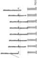
- the lead 10 is then lowered toward the seabed floor F.
- the lead 10 is maintained in a vertical position, which can be monitored with, for example, inclinometers, plumb system, or hand held level tools.
- the tip portion 16a of the lead 16 will initially be inserted into the opening of an existing foundation structure 60, e.g., previously installed pile.
- the tapered surface between the tip portion 16a and fitted portion 16b pilots the lead indexing foot 16 until the existing foundation structure contacts the base portion 16c of the lead indexing foot 16.
- the lead indexing foot 16 is inserted into and is supported by the existing foundation structure 60. In this configuration, the lead 10 is substantially connected to the lead indexing foot 16.
- the lead 10 may have a second lead indexing foot 18 that is configured to engage another portion of the existing foundation structure 60 in a similar manner as the previously discussed, first lead indexing foot 16.
- the second lead indexing foot 18 may extend along an axis Y3 that is laterally offset from axes Y1 and Y2.
- the second lead indexing foot 18 may have a similar shape as the first lead indexing foot 16 and be disposed on the second end 10b of the lead 10.
- FIGS. 5 and 6 after at least one lead indexing foot 16 is fully inserted into the existing foundation structure 60, the pile 50 that is loaded in the lead 10 is in proper alignment and can be lowered.
- the pile 50 has interlocks 50m, 50f that is adapted to engage interlocks 60m, 60f of the existing foundation structure 60.
- pile 50 may have a male type interlock 50m that extends along a length of the pile 50, parallel to axis Y1.
- the existing foundation structure 60 which may be an existing pile, may have a female type interlock 60f that extends along a length of the existing foundation structure 60, parallel to axis Y2. Therefore, when the pile 50 is being lowered toward the seabed floor F, the respective interlocks 50m, 60f engage each other.
- Any suitable interlocking means may be implemented, for example a T-shaped protrusion and a corresponding channel. Cameras and/or sensors may be used to ensure that the respective interlocks 50m, 60f are properly engaged.
- the gates 14 are opened allowing the pile 50 to be lowered to the seabed floor F.
- the pile insertion device 40 drives the pile 50 therein.
- the pile insertion device 40 may be an impact hammer, a vibratory hammer, or a means to drill the pile 50 into the seabed floor F.
- a feedback means may be used with the gates 14, for example hydraulic flags configured to provide visual feedback on the gate position (open/close) even when water turbidity prevents visual confirmation or during a night time installation.
- the lead 10 is elevated vertically, away from the seabed floor F.
- the lead 10 is moved back into its initial position and thereafter disconnected from the template 20.
- a new pile can be loaded into the lead 10. This may be done concurrently with moving the template 20 to the next position.
- the template 20 may be advanced using a wire rope, winches, or hydraulically actuated cylinders.
- the benefits of performing this method of operation using the lead 10 having at least one lead indexing foot 16 is that lowering the lead indexing foot 16 into the existing foundation structure 60, e.g., previously installed piles, fine tunes the alignment of the lead 10 at seabed elevation and allows the lead 10 to index using the existing foundation structure 60. Further, because the lead 10 is indexed with both the existing foundation structure 60 and the template 20, it is possible to determine the position and alignment of the existing foundation structure 60 by surveying or instrumentation on the lead 10. This enables installation of a seabed wall during times with low viability, for example, turbulent water or night.
- An alternative method of installing a pile 50 into the seabed floor F is similar to the previous method, except that the lead 10 is connected to the template 20 without having a pile 50 loaded therein. The lead 10 is then lowered toward the seabed floor F. Similar to the previous exemplary method, the lead indexing foot 16 is inserted into and is supported by the existing foundation structure 60. Also similar to the previous method, it is envisioned that the lead 10 may have a second lead indexing foot 18 that is configured to engage another portion of the existing foundation structure 60.
- the pile 50 is loaded into or onto the lead 10 and secured with a movable gate 14. The pile 50 is then lowered toward the seabed floor F.
- the gates 14 are opened allowing the pile 50 to be lowered to the seabed floor F and the pile insertion device 40 drives the pile 50 therein.
- the lead 10 is elevated vertically, away from the seabed floor F and into its initial position. Thereafter, the lead 10 can be moved concurrently with the template 20 to the next position.
- the lead 10 and template 20 assembly may be advanced using a wire rope, winches, or hydraulically actuated cylinders.
- the benefits of performing this method of operation using the lead 10 having at least one lead indexing foot 16 is that lowering the lead indexing foot 16 into the existing foundation structure 60 remains the same as the previous method in that the lead indexing foot 16 fine tunes the alignment of the lead 10 at seabed elevation and allows the lead 10 to index using the existing foundation structure 60.
- the installation is occurring in placid or calm water, refraining from disconnecting the lead 10 from the template 20 after every pile 50 is driven, and adjusting the lead 10 with the template 20, expedites the installation process.
Landscapes
- Engineering & Computer Science (AREA)
- Structural Engineering (AREA)
- General Engineering & Computer Science (AREA)
- Mining & Mineral Resources (AREA)
- Paleontology (AREA)
- Civil Engineering (AREA)
- Life Sciences & Earth Sciences (AREA)
- General Life Sciences & Earth Sciences (AREA)
- Chemical & Material Sciences (AREA)
- Composite Materials (AREA)
- Placing Or Removing Of Piles Or Sheet Piles, Or Accessories Thereof (AREA)
- Electric Cable Installation (AREA)
- Laying Of Electric Cables Or Lines Outside (AREA)
- Foundations (AREA)
- Earth Drilling (AREA)
Claims (7)
- Verfahren zum Eintreiben eines Pfahls (50) in einen Meeresboden (F) angrenzend an eine bestehende Fundamentstruktur (60), das Verfahren umfassend:Absenken einer längs ausgerichteten Führung (10), in einer ersten Richtung zu dem Unterwasserboden (F);Eingreifen eines Indexierungsfußes (16) der Führung (10) mit der vorhandenen Fundamentstruktur (60); undVorschieben des Pfahls (50) entlang der Führung (10) in der ersten Richtung in den Unterwasserboden (F).
- Verfahren nach Anspruch 1, ferner umfassend ein Einsetzen einer Verriegelung (50m) des Pfahls (50) in eine Verriegelung (60f) der vorhandenen Fundamentstruktur (60).
- Verfahren nach Anspruch 2, ferner umfassend ein Bestimmen, ob die Verriegelung (50m) des Pfahls (50) die Verriegelung (60f) der angrenzenden vorhandenen Fundamentstruktur (60) eingegriffen hat.
- Verfahren nach einem der Ansprüche 1 bis 3, ferner umfassend ein Anbringen der Führung (10) an einer Schablone (20), die angepasst ist, um sich in einer zweiten Richtung zu bewegen, die senkrecht zu der ersten Richtung ist.
- Verfahren nach Anspruch 4, ferner umfassend ein Einstellen der Position der Führung (10) durch Bewegen der Schablone (20) auf mindestens einer Schiene.
- Verfahren nach einem der Ansprüche 1 bis 4, ferner umfassend ein Laden des Pfahls (50) auf die Führung (10) vor dem Schritt eines Absenkens der Führung (10) in der ersten Richtung.
- Verfahren nach einem der Ansprüche 1 bis 4, ferner umfassend ein Laden des Pfahls (50) auf die Führung (10) nach dem Schritt eines Absenkens der Führung (10).
Applications Claiming Priority (2)
| Application Number | Priority Date | Filing Date | Title |
|---|---|---|---|
| CA3004561A CA3004561A1 (en) | 2018-05-09 | 2018-05-09 | Apparatus and method for subsea wall insertion |
| PCT/EP2019/061744 WO2019215196A1 (en) | 2018-05-09 | 2019-05-07 | Apparatus and method for subsea wall insertion |
Publications (2)
| Publication Number | Publication Date |
|---|---|
| EP3791024A1 EP3791024A1 (de) | 2021-03-17 |
| EP3791024B1 true EP3791024B1 (de) | 2025-06-25 |
Family
ID=68465402
Family Applications (1)
| Application Number | Title | Priority Date | Filing Date |
|---|---|---|---|
| EP19724139.1A Active EP3791024B1 (de) | 2018-05-09 | 2019-05-07 | Verfahren zum einsetzen eines pfahls im meeresboden |
Country Status (10)
| Country | Link |
|---|---|
| US (1) | US11795649B2 (de) |
| EP (1) | EP3791024B1 (de) |
| AU (1) | AU2019267002B2 (de) |
| CA (1) | CA3004561A1 (de) |
| CL (1) | CL2020002899A1 (de) |
| ES (1) | ES3040409T3 (de) |
| MX (1) | MX2020011687A (de) |
| PE (1) | PE20201412A1 (de) |
| PL (1) | PL3791024T3 (de) |
| WO (1) | WO2019215196A1 (de) |
Families Citing this family (1)
| Publication number | Priority date | Publication date | Assignee | Title |
|---|---|---|---|---|
| CN112302022A (zh) * | 2020-11-11 | 2021-02-02 | 中铁二十二局集团第五工程有限公司 | 一种深水基础钢板桩插打导向定位装置 |
Citations (1)
| Publication number | Priority date | Publication date | Assignee | Title |
|---|---|---|---|---|
| EP0059648A1 (de) * | 1981-03-04 | 1982-09-08 | John T. Ostgaard | Verfahren und Vorrichtung zum Verankern von Off-shore-Konstruktionen |
Family Cites Families (14)
| Publication number | Priority date | Publication date | Assignee | Title |
|---|---|---|---|---|
| US5800096A (en) * | 1995-04-27 | 1998-09-01 | Barrow; Jeffrey | Subsurface barrier wall and method of installation |
| JPH11256576A (ja) | 1998-03-13 | 1999-09-21 | Toyohisa Kageyama | 杭圧入装置 |
| ATE329127T1 (de) * | 2001-12-05 | 2006-06-15 | Comacchio S R L | Bohrmast mit beweglichem und festgelegtem abschraub-schraubstock |
| KR100635106B1 (ko) * | 2004-03-05 | 2006-10-17 | 윤은중 | 천공시스템 및 그 방법 |
| ITTO20050682A1 (it) | 2005-09-30 | 2007-04-01 | Soilmec Spa | Metodo ed attrezzatura per realizzare un diaframma impermeabile di pali secanti. |
| NL1033368C2 (nl) | 2007-02-09 | 2008-08-12 | Kandt Aannemings Funderingsbed | Werkwijze en installatie voor het in een onder water gelegen bodem inbrengen van een damwand. |
| CA2760500C (en) | 2009-05-01 | 2017-10-24 | Jay Gunnarson | Telescoping leader system |
| PL2354321T3 (pl) * | 2010-01-13 | 2013-05-31 | Geosea Nv | Sposób wykonywania fundamentu pod wzniesioną masę oraz zespół platformy samopodnośnej i szablon ramowy, przeznaczone do realizacji tego sposobu |
| US9677340B1 (en) | 2011-06-23 | 2017-06-13 | Bernard J. Gochis | High speed precision guide device for creating holes for piles or other support members |
| TR201807586T4 (en) | 2012-09-21 | 2018-07-23 | Soletanche Freyssinet | STRUCTURE BUILDING APPARATUS AND CONSTRUCTION METHOD USED IN THIS APPARATUS. |
| CN105089053B (zh) | 2015-09-14 | 2017-02-01 | 山河智能装备股份有限公司 | 一种桩架及其使用安装方法 |
| JP6074017B1 (ja) * | 2015-11-30 | 2017-02-01 | 東亜建設工業株式会社 | 杭打設システム |
| JP6660819B2 (ja) * | 2016-06-13 | 2020-03-11 | 鹿島建設株式会社 | 杭ガイド及び杭打設方法 |
| JP7048362B2 (ja) * | 2018-03-13 | 2022-04-05 | 日本車輌製造株式会社 | 杭打機 |
-
2018
- 2018-05-09 CA CA3004561A patent/CA3004561A1/en active Pending
-
2019
- 2019-05-07 US US17/053,465 patent/US11795649B2/en active Active
- 2019-05-07 PL PL19724139.1T patent/PL3791024T3/pl unknown
- 2019-05-07 PE PE2020001805A patent/PE20201412A1/es unknown
- 2019-05-07 WO PCT/EP2019/061744 patent/WO2019215196A1/en not_active Ceased
- 2019-05-07 MX MX2020011687A patent/MX2020011687A/es unknown
- 2019-05-07 EP EP19724139.1A patent/EP3791024B1/de active Active
- 2019-05-07 AU AU2019267002A patent/AU2019267002B2/en active Active
- 2019-05-07 ES ES19724139T patent/ES3040409T3/es active Active
-
2020
- 2020-11-09 CL CL2020002899A patent/CL2020002899A1/es unknown
Patent Citations (1)
| Publication number | Priority date | Publication date | Assignee | Title |
|---|---|---|---|---|
| EP0059648A1 (de) * | 1981-03-04 | 1982-09-08 | John T. Ostgaard | Verfahren und Vorrichtung zum Verankern von Off-shore-Konstruktionen |
Also Published As
| Publication number | Publication date |
|---|---|
| US11795649B2 (en) | 2023-10-24 |
| CA3004561A1 (en) | 2019-11-09 |
| WO2019215196A1 (en) | 2019-11-14 |
| ES3040409T3 (en) | 2025-10-30 |
| PE20201412A1 (es) | 2020-12-04 |
| CL2020002899A1 (es) | 2021-07-19 |
| PL3791024T3 (pl) | 2025-11-03 |
| EP3791024A1 (de) | 2021-03-17 |
| AU2019267002B2 (en) | 2024-11-07 |
| AU2019267002A1 (en) | 2020-11-19 |
| MX2020011687A (es) | 2020-12-10 |
| US20210222387A1 (en) | 2021-07-22 |
Similar Documents
| Publication | Publication Date | Title |
|---|---|---|
| US3852970A (en) | Building raising and underpinning system | |
| US9371623B2 (en) | Diaphragm wall apparatus and methods | |
| CN206721958U (zh) | 一种大直径全自动沉井挖掘系统 | |
| CA1189708A (en) | J-tube method and apparatus | |
| US9151011B2 (en) | Drilling device for executing diaphragm walls and method thereof | |
| JP2021510780A (ja) | 掘削またはボーリング装置用アセンブリおよび作動方法 | |
| EP3791024B1 (de) | Verfahren zum einsetzen eines pfahls im meeresboden | |
| CN108999225B (zh) | 旋转移位砖混结构建筑物纠倾法 | |
| JP2015169018A (ja) | 自己姿勢制御型沈埋函と沈埋トンネルの施工方法 | |
| US8632275B2 (en) | Excavation machine with a pivotable kelly bar | |
| KR102637552B1 (ko) | 천공 및 항타 작업의 동시수행이 가능한 파일 시공장치 | |
| EP1270824B1 (de) | Herstellung einer Unterwasserwand | |
| CN114370234A (zh) | 一种裸岩河床钢管桩施工设备及施工方法 | |
| JP4941863B2 (ja) | キーエレメント工法による沈埋函の最終接合方法 | |
| JP2012167421A (ja) | コンクリート土木構造物の地盤沈下量測定装置及びその施工方法 | |
| CN115030136B (zh) | 管线横穿基坑区域地下连续墙的施工方法 | |
| CN106120802A (zh) | 紧临既有线大跨度连续梁深水基础水下基坑开挖施工方法 | |
| CN204690772U (zh) | 一种深水桩基定位、导向结构 | |
| CN116348643A (zh) | 土木工程机械以及用于挖土的土木工程方法 | |
| JP4230231B2 (ja) | 水中連続コア削孔工法 | |
| CN109469080B (zh) | 一种水下嵌岩钢板桩围堰结构及其施工方法 | |
| JP2017020518A (ja) | 管据付位置誘導装置及び管敷設方法 | |
| CN116838379B (zh) | 一种保护地铁兼顾地下室结构的桩管幕支护结构 | |
| CN211113637U (zh) | 一种桩基施工时的桩位弃土清理装置 | |
| EP2226427B1 (de) | Aushubvorrichtung |
Legal Events
| Date | Code | Title | Description |
|---|---|---|---|
| STAA | Information on the status of an ep patent application or granted ep patent |
Free format text: STATUS: UNKNOWN |
|
| STAA | Information on the status of an ep patent application or granted ep patent |
Free format text: STATUS: THE INTERNATIONAL PUBLICATION HAS BEEN MADE |
|
| PUAI | Public reference made under article 153(3) epc to a published international application that has entered the european phase |
Free format text: ORIGINAL CODE: 0009012 |
|
| STAA | Information on the status of an ep patent application or granted ep patent |
Free format text: STATUS: REQUEST FOR EXAMINATION WAS MADE |
|
| 17P | Request for examination filed |
Effective date: 20201113 |
|
| AK | Designated contracting states |
Kind code of ref document: A1 Designated state(s): AL AT BE BG CH CY CZ DE DK EE ES FI FR GB GR HR HU IE IS IT LI LT LU LV MC MK MT NL NO PL PT RO RS SE SI SK SM TR |
|
| AX | Request for extension of the european patent |
Extension state: BA ME |
|
| DAV | Request for validation of the european patent (deleted) | ||
| DAX | Request for extension of the european patent (deleted) | ||
| STAA | Information on the status of an ep patent application or granted ep patent |
Free format text: STATUS: EXAMINATION IS IN PROGRESS |
|
| 17Q | First examination report despatched |
Effective date: 20221216 |
|
| P01 | Opt-out of the competence of the unified patent court (upc) registered |
Effective date: 20230528 |
|
| GRAP | Despatch of communication of intention to grant a patent |
Free format text: ORIGINAL CODE: EPIDOSNIGR1 |
|
| STAA | Information on the status of an ep patent application or granted ep patent |
Free format text: STATUS: GRANT OF PATENT IS INTENDED |
|
| INTG | Intention to grant announced |
Effective date: 20250218 |
|
| GRAS | Grant fee paid |
Free format text: ORIGINAL CODE: EPIDOSNIGR3 |
|
| GRAA | (expected) grant |
Free format text: ORIGINAL CODE: 0009210 |
|
| STAA | Information on the status of an ep patent application or granted ep patent |
Free format text: STATUS: THE PATENT HAS BEEN GRANTED |
|
| AK | Designated contracting states |
Kind code of ref document: B1 Designated state(s): AL AT BE BG CH CY CZ DE DK EE ES FI FR GB GR HR HU IE IS IT LI LT LU LV MC MK MT NL NO PL PT RO RS SE SI SK SM TR |
|
| REG | Reference to a national code |
Ref country code: GB Ref legal event code: FG4D |
|
| REG | Reference to a national code |
Ref country code: CH Ref legal event code: EP |
|
| REG | Reference to a national code |
Ref country code: DE Ref legal event code: R096 Ref document number: 602019071526 Country of ref document: DE |
|
| REG | Reference to a national code |
Ref country code: CH Ref legal event code: EP |
|
| REG | Reference to a national code |
Ref country code: IE Ref legal event code: FG4D |
|
| PG25 | Lapsed in a contracting state [announced via postgrant information from national office to epo] |
Ref country code: FI Free format text: LAPSE BECAUSE OF FAILURE TO SUBMIT A TRANSLATION OF THE DESCRIPTION OR TO PAY THE FEE WITHIN THE PRESCRIBED TIME-LIMIT Effective date: 20250625 |
|
| REG | Reference to a national code |
Ref country code: LT Ref legal event code: MG9D |
|
| PG25 | Lapsed in a contracting state [announced via postgrant information from national office to epo] |
Ref country code: NO Free format text: LAPSE BECAUSE OF FAILURE TO SUBMIT A TRANSLATION OF THE DESCRIPTION OR TO PAY THE FEE WITHIN THE PRESCRIBED TIME-LIMIT Effective date: 20250925 Ref country code: GR Free format text: LAPSE BECAUSE OF FAILURE TO SUBMIT A TRANSLATION OF THE DESCRIPTION OR TO PAY THE FEE WITHIN THE PRESCRIBED TIME-LIMIT Effective date: 20250926 |
|
| PG25 | Lapsed in a contracting state [announced via postgrant information from national office to epo] |
Ref country code: BG Free format text: LAPSE BECAUSE OF FAILURE TO SUBMIT A TRANSLATION OF THE DESCRIPTION OR TO PAY THE FEE WITHIN THE PRESCRIBED TIME-LIMIT Effective date: 20250625 |
|
| PG25 | Lapsed in a contracting state [announced via postgrant information from national office to epo] |
Ref country code: HR Free format text: LAPSE BECAUSE OF FAILURE TO SUBMIT A TRANSLATION OF THE DESCRIPTION OR TO PAY THE FEE WITHIN THE PRESCRIBED TIME-LIMIT Effective date: 20250625 |
|
| PG25 | Lapsed in a contracting state [announced via postgrant information from national office to epo] |
Ref country code: RS Free format text: LAPSE BECAUSE OF FAILURE TO SUBMIT A TRANSLATION OF THE DESCRIPTION OR TO PAY THE FEE WITHIN THE PRESCRIBED TIME-LIMIT Effective date: 20250925 |
|
| PG25 | Lapsed in a contracting state [announced via postgrant information from national office to epo] |
Ref country code: LV Free format text: LAPSE BECAUSE OF FAILURE TO SUBMIT A TRANSLATION OF THE DESCRIPTION OR TO PAY THE FEE WITHIN THE PRESCRIBED TIME-LIMIT Effective date: 20250625 |
|
| REG | Reference to a national code |
Ref country code: NL Ref legal event code: MP Effective date: 20250625 |
|
| REG | Reference to a national code |
Ref country code: ES Ref legal event code: FG2A Ref document number: 3040409 Country of ref document: ES Kind code of ref document: T3 Effective date: 20251030 |
|
| PG25 | Lapsed in a contracting state [announced via postgrant information from national office to epo] |
Ref country code: NL Free format text: LAPSE BECAUSE OF FAILURE TO SUBMIT A TRANSLATION OF THE DESCRIPTION OR TO PAY THE FEE WITHIN THE PRESCRIBED TIME-LIMIT Effective date: 20250625 |
|
| PG25 | Lapsed in a contracting state [announced via postgrant information from national office to epo] |
Ref country code: PT Free format text: LAPSE BECAUSE OF FAILURE TO SUBMIT A TRANSLATION OF THE DESCRIPTION OR TO PAY THE FEE WITHIN THE PRESCRIBED TIME-LIMIT Effective date: 20251027 |
|
| REG | Reference to a national code |
Ref country code: AT Ref legal event code: MK05 Ref document number: 1806557 Country of ref document: AT Kind code of ref document: T Effective date: 20250625 |
|
| PG25 | Lapsed in a contracting state [announced via postgrant information from national office to epo] |
Ref country code: IS Free format text: LAPSE BECAUSE OF FAILURE TO SUBMIT A TRANSLATION OF THE DESCRIPTION OR TO PAY THE FEE WITHIN THE PRESCRIBED TIME-LIMIT Effective date: 20251025 |
|
| PG25 | Lapsed in a contracting state [announced via postgrant information from national office to epo] |
Ref country code: AT Free format text: LAPSE BECAUSE OF FAILURE TO SUBMIT A TRANSLATION OF THE DESCRIPTION OR TO PAY THE FEE WITHIN THE PRESCRIBED TIME-LIMIT Effective date: 20250625 Ref country code: SM Free format text: LAPSE BECAUSE OF FAILURE TO SUBMIT A TRANSLATION OF THE DESCRIPTION OR TO PAY THE FEE WITHIN THE PRESCRIBED TIME-LIMIT Effective date: 20250625 |
|
| PG25 | Lapsed in a contracting state [announced via postgrant information from national office to epo] |
Ref country code: CZ Free format text: LAPSE BECAUSE OF FAILURE TO SUBMIT A TRANSLATION OF THE DESCRIPTION OR TO PAY THE FEE WITHIN THE PRESCRIBED TIME-LIMIT Effective date: 20250625 |
|
| PG25 | Lapsed in a contracting state [announced via postgrant information from national office to epo] |
Ref country code: EE Free format text: LAPSE BECAUSE OF FAILURE TO SUBMIT A TRANSLATION OF THE DESCRIPTION OR TO PAY THE FEE WITHIN THE PRESCRIBED TIME-LIMIT Effective date: 20250625 |
|
| PG25 | Lapsed in a contracting state [announced via postgrant information from national office to epo] |
Ref country code: SK Free format text: LAPSE BECAUSE OF FAILURE TO SUBMIT A TRANSLATION OF THE DESCRIPTION OR TO PAY THE FEE WITHIN THE PRESCRIBED TIME-LIMIT Effective date: 20250625 |