EP3790485B1 - Epicardial ablation catheter - Google Patents
Epicardial ablation catheter Download PDFInfo
- Publication number
- EP3790485B1 EP3790485B1 EP19725482.4A EP19725482A EP3790485B1 EP 3790485 B1 EP3790485 B1 EP 3790485B1 EP 19725482 A EP19725482 A EP 19725482A EP 3790485 B1 EP3790485 B1 EP 3790485B1
- Authority
- EP
- European Patent Office
- Prior art keywords
- electrodes
- ablation device
- ablation
- cinch
- electrode
- Prior art date
- Legal status (The legal status is an assumption and is not a legal conclusion. Google has not performed a legal analysis and makes no representation as to the accuracy of the status listed.)
- Active
Links
Images


Classifications
-
- A—HUMAN NECESSITIES
- A61—MEDICAL OR VETERINARY SCIENCE; HYGIENE
- A61B—DIAGNOSIS; SURGERY; IDENTIFICATION
- A61B18/00—Surgical instruments, devices or methods for transferring non-mechanical forms of energy to or from the body
- A61B18/04—Surgical instruments, devices or methods for transferring non-mechanical forms of energy to or from the body by heating
- A61B18/12—Surgical instruments, devices or methods for transferring non-mechanical forms of energy to or from the body by heating by passing a current through the tissue to be heated, e.g. high-frequency current
- A61B18/14—Probes or electrodes therefor
- A61B18/1492—Probes or electrodes therefor having a flexible, catheter-like structure, e.g. for heart ablation
-
- A—HUMAN NECESSITIES
- A61—MEDICAL OR VETERINARY SCIENCE; HYGIENE
- A61B—DIAGNOSIS; SURGERY; IDENTIFICATION
- A61B18/00—Surgical instruments, devices or methods for transferring non-mechanical forms of energy to or from the body
- A61B2018/00053—Mechanical features of the instrument of device
- A61B2018/00166—Multiple lumina
-
- A—HUMAN NECESSITIES
- A61—MEDICAL OR VETERINARY SCIENCE; HYGIENE
- A61B—DIAGNOSIS; SURGERY; IDENTIFICATION
- A61B18/00—Surgical instruments, devices or methods for transferring non-mechanical forms of energy to or from the body
- A61B2018/00315—Surgical instruments, devices or methods for transferring non-mechanical forms of energy to or from the body for treatment of particular body parts
- A61B2018/00345—Vascular system
- A61B2018/00351—Heart
- A61B2018/00363—Epicardium
-
- A—HUMAN NECESSITIES
- A61—MEDICAL OR VETERINARY SCIENCE; HYGIENE
- A61B—DIAGNOSIS; SURGERY; IDENTIFICATION
- A61B18/00—Surgical instruments, devices or methods for transferring non-mechanical forms of energy to or from the body
- A61B2018/00315—Surgical instruments, devices or methods for transferring non-mechanical forms of energy to or from the body for treatment of particular body parts
- A61B2018/00345—Vascular system
- A61B2018/00351—Heart
- A61B2018/00375—Ostium, e.g. ostium of pulmonary vein or artery
-
- A—HUMAN NECESSITIES
- A61—MEDICAL OR VETERINARY SCIENCE; HYGIENE
- A61B—DIAGNOSIS; SURGERY; IDENTIFICATION
- A61B18/00—Surgical instruments, devices or methods for transferring non-mechanical forms of energy to or from the body
- A61B2018/00571—Surgical instruments, devices or methods for transferring non-mechanical forms of energy to or from the body for achieving a particular surgical effect
- A61B2018/00577—Ablation
-
- A—HUMAN NECESSITIES
- A61—MEDICAL OR VETERINARY SCIENCE; HYGIENE
- A61B—DIAGNOSIS; SURGERY; IDENTIFICATION
- A61B18/00—Surgical instruments, devices or methods for transferring non-mechanical forms of energy to or from the body
- A61B2018/00571—Surgical instruments, devices or methods for transferring non-mechanical forms of energy to or from the body for achieving a particular surgical effect
- A61B2018/00613—Irreversible electroporation
-
- A—HUMAN NECESSITIES
- A61—MEDICAL OR VETERINARY SCIENCE; HYGIENE
- A61B—DIAGNOSIS; SURGERY; IDENTIFICATION
- A61B18/00—Surgical instruments, devices or methods for transferring non-mechanical forms of energy to or from the body
- A61B18/04—Surgical instruments, devices or methods for transferring non-mechanical forms of energy to or from the body by heating
- A61B18/12—Surgical instruments, devices or methods for transferring non-mechanical forms of energy to or from the body by heating by passing a current through the tissue to be heated, e.g. high-frequency current
- A61B18/14—Probes or electrodes therefor
- A61B2018/1405—Electrodes having a specific shape
- A61B2018/1407—Loop
-
- A—HUMAN NECESSITIES
- A61—MEDICAL OR VETERINARY SCIENCE; HYGIENE
- A61B—DIAGNOSIS; SURGERY; IDENTIFICATION
- A61B18/00—Surgical instruments, devices or methods for transferring non-mechanical forms of energy to or from the body
- A61B18/04—Surgical instruments, devices or methods for transferring non-mechanical forms of energy to or from the body by heating
- A61B18/12—Surgical instruments, devices or methods for transferring non-mechanical forms of energy to or from the body by heating by passing a current through the tissue to be heated, e.g. high-frequency current
- A61B18/14—Probes or electrodes therefor
- A61B2018/1467—Probes or electrodes therefor using more than two electrodes on a single probe
-
- A—HUMAN NECESSITIES
- A61—MEDICAL OR VETERINARY SCIENCE; HYGIENE
- A61B—DIAGNOSIS; SURGERY; IDENTIFICATION
- A61B18/00—Surgical instruments, devices or methods for transferring non-mechanical forms of energy to or from the body
- A61B18/04—Surgical instruments, devices or methods for transferring non-mechanical forms of energy to or from the body by heating
- A61B18/12—Surgical instruments, devices or methods for transferring non-mechanical forms of energy to or from the body by heating by passing a current through the tissue to be heated, e.g. high-frequency current
- A61B18/14—Probes or electrodes therefor
- A61B2018/1497—Electrodes covering only part of the probe circumference
Definitions
- Several embodiments therein disclose medical systems comprising a combination of one or more medical components and one or more elongate steerable or non-steerable arms that are adapted to mechanically manipulate the one or more medical components.
- Several embodiments of microwave antennas are disclosed that comprise an additional diagnostic or therapeutic modality located on or in the vicinity of the microwave antennas.
- a system may comprise an ablation device including a proximal portion, a distal portion, and a central portion, the central portion including a set of electrodes disposed thereon.
- a cinch device may define a first lumen configured to slidably receive the proximal portion of the ablation device and a second lumen may extend parallel to the first lumen and be configured to slidably receive the distal portion of the ablation device, such that the central portion of the ablation device forms an adjustable loop when the proximal and distal portions of the ablation device are received in the first and second lumens of the cinch device.
- the set of electrodes includes subsets of electrodes, each subset of electrodes has a first length, and adjacent subsets of electrodes are spaced from each other by a second length. In some of these embodiments, the set of electrodes includes between about 4 electrode subsets and about 20 electrode subsets.
- the ablation device includes first and second sets of fiducials. Fiducials of the first and second sets of fiducials are alternately disposed along a length of the ablation device, and the first set of fiducials differs from the second set of fiducials by one or more characteristics. Adjacent fiducials of the first set of fiducials are spaced apart by a sum of the first and second lengths. In some embodiments, the first and second set of fiducials may be disposed along at least one of the proximal and distal portions of the ablation device. In some embodiments, the one or more characteristics may include at least one of: a length, a thickness, a depth, a shape, a color, a pattern, an orientation, a texture, or a material.
- a fiducial of the first set of fiducials is spaced from an adjacent fiducial of the second set of fiducials by a third length equal to a width of an electrode of the set of electrodes.
- the cinch device may have a fourth length being an integer multiple of a sum of the first and second lengths.
- each subset of electrodes includes a plurality of electrodes, each electrode of the plurality of electrodes having a third length and being spaced from an adjacent electrode of the plurality of electrodes by a distance.
- the ablation device including a set of fiducials with spacing between adjacent proximal fiducials may alternate between a fourth length equal to the third length and a fifth length equal to the distance.
- each subset of electrodes may include a plurality of electrodes, a first electrode of the plurality of electrodes having a third length and a second electrode of the plurality of electrodes having a fourth length greater than the third length.
- the ablation device may include first and second sets of fiducials alternately disposed along a length of the ablation device, with a fiducial of the first set of fiducials being spaced from an adjacent fiducial of the second set of fiducials by the third length.
- the ablation device may be configured to transition between a first configuration in which the ablation device extends linearly and a second configuration in which the central portion of the ablation device forms the adjustable loop.
- the adjustable loop may be configured to be positioned around a set of pulmonary veins of a heart.
- the set of electrodes may be configured to generate a pulsed electric field to ablate cardiac tissue in response to receiving a voltage pulse waveform.
- the ablation device may include a handle coupled to a proximal end of the proximal portion of the ablation device.
- the ablation device may be a catheter including a guidewire lumen configured to receive a guidewire, such that the catheter can be positioned around a set of pulmonary veins of a heart using a guidewire.
- a lock may be configured to hold the ablation device in place relative to the cinch device.
- each electrode of the set of electrodes may include a length of between about 1 mm and about 12 mm.
- the distal portion of the ablation device may have a length of between about 20 cm and about 70 cm.
- an apparatus may comprise an elongate shaft defining first and second lumens extending parallel to one another, the first and second lumens configured to slidably receive opposite ends of an ablation catheter such that the ablation catheter forms an adjustable loop extending from the elongate shaft when the opposite ends of the ablation catheter are received within the first and second lumens, the elongate shaft including a proximal portion defining a longitudinal axis and a distal portion having a curvature relative to the longitudinal axis of the proximal portion.
- the curvature of the distal portion may be between about 30 degrees and about 60 degrees relative to the longitudinal axis of the proximal portion.
- the elongate shaft may have a length of between about 6 cm and about 30 cm.
- at least a distal end of the elongate shaft may be configured to be visualized fluoroscopically.
- the first and second lumens have the same diameter.
- the first and second lumens may be configured to slidably receive a portion of the ablation device having one or more electrodes disposed thereon.
- the first and second lumens may be configured to slidably receive the opposite ends of the ablation catheter such that at least one of the opposite ends of the ablation device can be moved relative to the elongate shaft to adjust a positioning of the adjustable loop around a portion of a heart.
- at least a portion of the tubular shaft is configured to be disposed within a pericardial space.
- a method which does not form part of the invention may comprise advancing a distal end of an ablation device through a first lumen of a cinch device in a proximal-to-distal direction.
- the ablation device may be positioned around cardiac tissue of a heart of a subject such that the ablation device forms an adjustable loop that circles around a set of pulmonary veins of the heart.
- the distal end of the ablation device may be advanced through a second lumen of the cinch device in a distal-to-proximal direction.
- the second lumen may extend substantially parallel to the first lumen.
- At least one of the distal end or a proximal end of the ablation device may be moved proximally from a proximal end of the cinch device to reduce a size of the adjustable loop and increase contact between the ablation device and the cardiac tissue.
- the adjustable loop of the ablation device extends through a pericardial reflection of the heart. In some embodiments, moving the at least one of the distal or proximal ends of the ablation device proximally from a proximal end of the cinch device applies a predetermined force via the ablation device to the cardiac tissue. In some embodiments, the method may further comprise advancing the cinch device into a pericardial space of the subject. In some embodiments, the method may further comprise positioning the cinch device on a posterior side of the heart. In some embodiments, the method may further comprise positioning the cinch device such that the clinch device is angled obliquely relative to a chest of the subject.
- the method may further comprise locking a position of the ablation device relative to the cinch device after moving the at least one of the distal or proximal end of the ablation device. In some embodiments, the method may further comprise delivering, via a set of electrodes of the ablation device, a pulsed electric field to the cardiac tissue to ablate the cardiac tissue.
- a method which does not form part of the invention may comprise advancing a distal end of an ablation device through a first lumen of a cinch device in a proximal-to-distal direction.
- the ablation device may be positioned around cardiac tissue of a heart of a subject such that the ablation device forms an adjustable loop that circles around a set of pulmonary veins of the heart.
- the distal end of the ablation device may be advanced through a second lumen of the cinch device in a distal-to-proximal direction, the second lumen extending substantially parallel to the first lumen.
- a position of a set of electrodes of the ablation device may be verified relative to the cinch device based at least on a set of fiducials disposed on at least one of a distal or proximal portion of the ablation device.
- the method may further comprise visualizing one or more fiducials of the set of fiducials of the ablation device disposed on a portion of the ablation device disposed outside of the cinch device.
- verifying a position of the set of electrodes of the ablation device includes identifying, using the set of fiducials, at least one electrode of the set of electrodes disposed distal to the cinch device.
- the method may further comprise applying a pulse waveform to the at least one electrode disposed distal to the cinch device and not to remaining electrodes of the set of electrodes.
- Described herein are systems, devices, and methods for selective and rapid application of pulsed electric fields to ablate tissue by irreversible electroporation.
- the systems, devices, and methods described herein may be used to generate large electric field magnitudes at desired regions of interest and reduce peak electric field values elsewhere in order to reduce unintended tissue damage.
- the devices described herein include flexible catheters that may be placed for pulsed electric field ablation of cardiac tissue.
- an ablation device may be placed via subxiphoid access or by direct surgical placement into the pericardial space.
- Proper physical placement and tension applied between an ablation device (e.g., ablation catheter) and tissue to be ablated may ensure targeted and effective electroporation with reduced side effects and user error.
- a cinch device and fiducials disposed thereon may be used to aid in positioning and verification of positioning of an ablation device relative to target tissue.
- An irreversible electroporation system as described herein may include a signal generator and a processor configured to apply one or more voltage pulse waveforms to a selected set of electrodes of an ablation device to deliver energy to a region of interest (e.g., ablation energy for tissue in a pulmonary vein ostium) and in one embodiment provide a highly configurable set of electrode channels (e.g., allow independent and arbitrary electrode selection).
- electrode pairings e.g., anode-cathode subsets
- the pulse waveforms disclosed herein may aid in therapeutic treatment of a variety of cardiac arrhythmias (e.g., atrial fibrillation).
- one or more electrodes of the ablation device may have an insulated electrical lead configured for sustaining a voltage potential of at least about 700 V without dielectric breakdown of its corresponding insulation.
- Subsets of electrodes may be independently addressable such that the subset may be controlled (e.g., deliver energy) independently of any other electrode of the device. In this manner, the electrodes and/or electrode subsets may deliver different energy waveforms with different timing synergistically for electroporation of tissue.
- electroporation refers to the application of an electric field to a cell membrane to change the permeability of the cell membrane to the extracellular environment.
- reversible electroporation refers to the application of an electric field to a cell membrane to temporarily change the permeability of the cell membrane to the extracellular environment.
- a cell undergoing reversible electroporation can observe the temporary and/or intermittent formation of one or more pores in its cell membrane that close up upon removal of the electric field.
- irreversible electroporation refers to the application of an electric field to a cell membrane to permanently change the permeability of the cell membrane to the extracellular environment.
- a cell undergoing irreversible electroporation can observe the formation of one or more pores in its cell membrane that persist upon removal of the electric field.
- Pulse waveforms for electroporation energy delivery as disclosed herein may enhance the safety, efficiency and effectiveness of energy delivery to tissue by reducing the electric field threshold associated with irreversible electroporation, thus yielding more effective ablative lesions with a reduction in total energy delivered.
- the voltage pulse waveforms disclosed herein may be hierarchical and have a nested structure.
- the pulse waveform may include hierarchical groupings of pulses having associated timescales. Examples of similar methods, systems, and devices are described in International Application Serial No.
- the systems may further include a cardiac stimulator used to synchronize the generation of the pulse waveform to a paced heartbeat.
- the cardiac stimulator may electrically pace the heart with a cardiac stimulator and ensure pacing capture to establish periodicity and predictability of the cardiac cycle.
- a time window within a refractory period of the periodic cardiac cycle may be selected for voltage pulse waveform delivery.
- voltage pulse waveforms may be delivered in the refractory period of the cardiac cycle so as to avoid disruption of the sinus rhythm of the heart.
- the system may optionally include one or more return electrodes.
- cardiac stimulator functionality may be integrated into a signal generator (e.g., ablation console, waveform generator console).
- one or more catheters may be advanced to a target location.
- the electrodes through which the voltage pulse waveform is delivered may be disposed on an epicardial device.
- the methods described here may include introducing an ablation catheter through a first lumen of a cinch device.
- the ablation catheter may be advanced out of the first lumen and looped around cardiac tissue such as a set of pulmonary veins.
- the distal end of the ablation catheter may be advanced back into the cinch device through a distal end of a second lumen.
- the ablation catheter may then be advanced out of the proximal end of the cinch device such that the proximal and distal ends of the ablation catheter are on the proximal side of the ablation catheter.
- the ends of the ablation catheter may be pulled away from the cinch device held in place such that the loop of the ablation catheter tightens around the tissue to increase contact and apply a predetermined force.
- a position of the ablation catheter relative to the cinch device may be verified using a set of fiducials disposed on the ablation catheter and/or cinch device.
- one or more electrodes and/or one or more subsets of electrodes may be disposed within a lumen of the cinch device. These electrodes may be non-activated for ablation.
- a pulse waveform may be generated and delivered to one or more identified electrodes of the ablation catheter (e.g., electrodes uncovered by the cinch device) to ablate tissue.
- the pulse waveform may be generated in synchronization with a pacing signal of the heart to avoid disruption of the sinus rhythm of the heart.
- the electrodes may be configured in anode-cathode subsets.
- the pulse waveform may include hierarchical waveforms to aid in tissue ablation and reduce damage to healthy tissue.
- a pulmonary vein isolation (PV isolation) system may include an ablation device (15) (e.g., ablation catheter), having a proximal portion (9) and a distal portion (8).
- ablation device e.g., ablation catheter
- the ablation device (15) may include a set of electrodes (17) disposed along its length, and where the ablation device (15) is wrapped in the epicardial space around all four pulmonary veins (10, 11, 12, 13) of a heart (7) in a subject or patient anatomy, with the proximal and distal portions (9) and (8) respectively of the ablation device (15) extending out and away to eventually emerge from the patient's chest.
- the ablation device (15) and any of the ablation devices described herein can be similar to the ablation catheters described in PCT Publication No. WO 2014/025394, entitled “Catheters, Catheter Systems, and Methods for Puncturing Through a Tissue Structure," filed on March 14, 2013 , as International Application Serial No.
- the ablation device (15) may be disposed about the pulmonary veins (10, 11, 12, 13) using any suitable procedure and apparatus.
- the ablation devices may be disposed about the pulmonary veins (10, 11, 12, 13) and/or the heart (7) using a puncturing apparatus disposed via a subxiphoid pericardial access location and using guidewire-based delivery methods as described in the '394 PCT Application Publication and/or International Application Serial No. PCT/US2017/037609, filed on June 15, 2017 .
- delivery catheters having magnetic members configured to form a magnetic coupling across a pericardial reflection can be used to deliver a guidewire into position around a heart. Similar and/or alternative methods can be used to deliver and position the ablation device (15).
- An alternative placement method includes direct surgical placement in an open chest, such as during a surgical procedure.
- the ablation device (15) may be inserted into one end of a proximal end of a first lumen of a double-barreled cinch device, as described in detail herein, then pulled through the lumen, placed around the base of one or more pulmonary veins to form a loop around the pulmonary veins, and then inserted into a distal end of a second lumen of the cinch device such that a distal end of the ablation device (15) extends from the proximal end of the second lumen of the cinch device.
- FIG. 14 illustrates a single catheter system
- the embodiments described herein may also apply to a two catheter system encircling the pulmonary veins such as described in International Application No. PCT/US2015/031086, entitled “METHODS AND APPARATUS FOR MULTI-CATHETER TISSUE ABLATION,” filed on May 15, 2015 .
- a voltage (e.g., DC voltage) for electroporation may be applied to subsets of electrodes identified as anodes and cathodes respectively on the two devices on approximately opposite sides of the closed contour defined by the shapes of the ablation device (15) around the pulmonary veins.
- the voltage may be applied in brief pulses sufficient to cause irreversible electroporation and may be in the range of 0.5 kV to 10 kV and more preferably in the range 1 kV to 2.5 kV, so that a threshold electric field value of around 200 Volts/cm may be effectively achieved in the cardiac tissue to be ablated.
- the active electrodes on the two devices may be automatically and/or manually identified on an X-ray or fluoroscopic image obtained at an appropriate angulation that permits identification of the geometric distance between anode and cathode electrodes, or their respective centroids.
- fiducials may be disposed on surfaces of one or more of the ablation device (15) and cinch device and may be configured to be visualized fluoroscopically to aid identification of electrode locations relative to the cinch device. Accordingly, a position of the ablation device (15) relative to the cinch device may be verified.
- the signal generator may be configured to deliver a voltage only to the subset of electrodes that are uncovered by the cinch device to deliver ablation energy to tissue.
- the voltage generator setting for irreversible electroporation may be automatically identified by the electroporation system based on this distance measure corresponding to electrode location.
- the voltage value may be selected directly by a user from a suitable dial, slider, touch screen, or any other user interface.
- the voltage pulse may result in a current flowing between the anode and cathode electrodes on opposite sides of the contour defined by the conjoint shapes of the two devices, with current flowing through the cardiac wall tissue and through the intervening blood in the cardiac chamber, with the current entering the cardiac tissue from the anode electrodes and returning back through the cathode electrodes.
- the forward and return current paths (leads) may be respectively disposed inside distinct devices and/or the same device.
- all active electrodes on a given device may be of like polarity.
- electrodes on a single device can be activated as anode-cathode sets. Areas of cardiac wall tissue where the electric field is sufficiently large for irreversible electroporation may be ablated during the voltage pulse application.
- the pulse waveform may be generated in synchronization with a pacing signal of the heart to avoid disruption of the sinus rhythm of the heart.
- the electrodes may be configured in anode-cathode (e.g., bipole) subsets.
- the pulse waveform may include hierarchical waveforms to aid in tissue ablation and reduce damage to healthy tissue, as described in International Application Serial No. PCT/US2016/057664 .
- electroporation refers to the application of an electric field to a cell membrane to change the permeability of the cell membrane to the extracellular environment.
- reversible electroporation refers to the application of an electric field to a cell membrane to temporarily change the permeability of the cell membrane to the extracellular environment.
- a cell undergoing reversible electroporation can observe the temporary and/or intermittent formation of one or more pores in its cell membrane that close up upon removal of the electric field.
- irreversible electroporation refers to the application of an electric field to a cell membrane to permanently change the permeability of the cell membrane to the extracellular environment.
- a cell undergoing irreversible electroporation can observe the formation of one or more pores in its cell membrane that persist upon removal of the electric field.
- Pulse waveforms for electroporation energy delivery as disclosed herein may enhance the safety, efficiency, and effectiveness of energy delivery to tissue by reducing the electric field threshold associated with irreversible electroporation, thus yielding more effective ablative lesions with a reduction in total energy delivered.
- the methods described here may include placing tissue (e.g., pulmonary vein) in contact with the electrodes.
- a pulse waveform may be generated and delivered to one or more electrodes of the device to ablate tissue.
- the pulse waveform may be generated in synchronization with a pacing signal of the heart to avoid disruption of the sinus rhythm of the heart.
- the electrodes may be configured in anode-cathode (e.g., bipole) subsets.
- the pulse waveform may include hierarchical waveforms to aid in tissue ablation and reduce damage to healthy tissue.
- a system for ablating tissue described here may include a signal generator and an ablation device having one or more electrodes for the selective and rapid application of DC voltage to drive electroporation.
- the systems and devices described herein include one or more ablation devices configured to ablate tissue of the heart. Voltages may be applied to a selected subset of the electrodes, with independent subset selections for anode and cathode electrode selections.
- the ablation device may be coupled to one or more electrode channels of the signal generator.
- Each electrode channel, or subset of electrode channels may be independently configured as an anode or cathode and a voltage pulse waveform may be delivered through one or more of the electrode channels in a predetermined sequence.
- a pacing signal for cardiac stimulation may be generated and used to generate the pulse waveform by the signal generator in synchronization with the pacing signal.
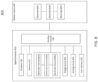
- FIG. 8 schematically illustrates an ablation system (800) configured to deliver voltage pulse waveforms for tissue ablation.
- the system (800) may include a signal generator (810) and ablation device (840).
- the signal generator (810) may be coupled to at least one ablation device (840) having a set of one or more electrodes (842a, 842b,..., 842n).
- the signal generator (810) may be configured to generate pulse waveforms for irreversible electroporation of tissue, such as, for example, heart tissue.
- the signal generator (810) may be a voltage pulse waveform generator and deliver a pulse waveform to a set of electrodes (842a, 842b,..., 842n,) of the ablation device (840).
- the signal generator (810) may generate and deliver several types of signals including, but not limited to, radiofrequency (RF), direct current (DC) impulses (such as high-voltage, ultra-short pulses used in electroporation), stimulus range impulses, and/or hybrid electrical impulses.
- RF radiofrequency
- DC direct current
- the signal generator (810) may generate monophasic (DC) pulses and biphasic (DC and AC) pulses.
- the signal generator (810) may include a processor (820), memory (822), a set of electrode channels (824a, 824b,..., 824n), energy source (826), sensing circuit (828), routing console (830), and user interface (832).
- One or more signal generator components may be coupled using a communication bus.
- the processor (820) may incorporate data received from one or more of memory (822), electrode channels (824a, 824b,..., 824n), energy source (826), sensing circuit (828), routing console (830), user interface (832), ablation device (840) to determine the parameters (e.g., amplitude, width, duty cycle, timing, etc.) of the voltage pulse waveform to be generated by the signal generator (810).
- the memory (822) may further store instructions to cause the processor (820) to execute modules, processes and/or functions associated with the system (800), such as pulse waveform generation and delivery, and/or electrode channel configuration.
- the memory (822) may be configured to store anode/cathode configuration data, electrode channel configuration data, pulse waveform data, fault data, energy discharge data, heart pacing data, patient data, clinical data, procedure data, sensor data, temperature data, and/or the like.
- the ablation device (840) may include a device configured to receive and/or deliver the pulse waveforms described herein.
- the ablation device (840) may be introduced around a pulmonary vein and positioned to align one or more electrodes (842a, 842b,..., 842n) to heart tissue, and then deliver the pulse waveforms to ablate tissue.
- the ablation device (840) may include one or more electrodes (842a, 842b,..., 842n), which may, in some embodiments, be a set of independently addressable electrodes.
- the electrodes (842a, 842b,..., 842n) may be grouped into one or more anode-cathode subsets such as, for example, a subset including one anode and one cathode, a subset including two anodes and two cathodes, a subset including two anodes and one cathode, a subset including one anode and two cathodes, a subset including three anodes and one cathode, a subset including three anodes and two cathodes, and/or the like.
- the set of electrodes (842a, 842b,..., 842n) may include any number of electrodes, for example, 2, 3, 4, 5, 6, 7, 8, 9, 10, 12, or more electrodes.
- PCT/US2013/031252 filed on March 14, 2013 , and titled "CATHETERS, CATHETER SYSTEMS, AND METHODS FOR PUNCTURING THROUGH A TISSUE STRUCTURE AND ABLATING A TISSUE REGION”; International Application Serial No. PCT/US2018/029552, filed on April 26, 2018 , and titled “SYSTEMS, DEVICES, AND METHODS FOR SIGNAL GENERATION”; and International Application Serial No. PCT/US2019/014226, filed on January 18, 2019 , and titled “SYSTEMS, DEVICES, AND METHODS FOR FOCAL ABLATION”.
- the processor (820) may be any suitable processing device configured to run and/or execute a set of instructions or code and may include one or more data processors, image processors, graphics processing units, physics processing units, digital signal processors, and/or central processing units.
- the processor (820) may be, for example, a general purpose processor, Field Programmable Gate Array (FPGA), an Application Specific Integrated Circuit (ASIC), and/or the like.
- the processor (820) may be configured to run and/or execute application processes and/or other modules, processes and/or functions associated with the system and/or a network associated therewith (not shown).
- the processor may include both a microcontroller unit and an FPGA unit, with the microcontroller sending electrode sequence instructions to the FPGA.
- MOSFET metal-oxide semiconductor field-effect transistor
- CMOS complementary metal-oxide semiconductor
- ECL emitter-coupled logic
- polymer technologies e.g., silicon-conjugated polymer and metal-conjugated polymer-metal structures
- mixed analog and digital and/or the like.
- the memory (822) may include a database (not shown) and may be, for example, a random access memory (RAM), a memory buffer, a hard drive, an erasable programmable read-only memory (EPROM), an electrically erasable read-only memory (EEPROM), a read-only memory (ROM), Flash memory, etc.
- the memory (822) may store instructions to cause the processor (820) to execute modules, processes and/or functions associated with the system (800), such as pulse waveform generation and/or electrode channel configuration.
- a set of electrode channels (824a, 824b,..., 824n) may include a set of active solid-state switches.
- the set of electrode channels (824a, 824b,..., 824n) may be configured in a number of ways, including independent anode/cathode configuration for each electrode channel.
- the electrode channels (824a, 824b,..., 824n) may be grouped into one or more anode-cathode subsets such as, for example, a subset including one anode and one cathode, a subset including two anodes and two cathodes, a subset including two anodes and one cathode, a subset including one anode and two cathodes, a subset including three anodes and one cathode, a subset including three anodes and two cathodes, and/or the like.
- the set of electrode channels (824a, 824b,..., 824n) may include any number of channels, for example, 2, 3, 4, 5, 6, 7, 8, 9, 10, 12, or more electrode channels.
- Energy delivery may use any combination of electrode channels (824a, 824b,..., 824n) and any order for an energy delivery sequence.
- the energy delivered may be an RF and/or any tissue ablation energy.
- the set of electrode channels (824a, 824b,..., 824n) may be coupled to a routing console (830) to deliver energy to a set of electrodes (842) coupled to the routing console (830).
- the set of electrode channels (824a, 824b,..., 824n) may be coupled to an energy source (826) to receive energy (e.g., a pulse waveform).
- Processor (820) may be coupled to each electrode channel (824a, 824b,..., 824n) to configure an anode/cathode configuration for each electrode channel (824), which may be configured on a per pulse basis, per operator input, and/or the like.
- each electrode channel (824a, 824b,..., 824n) may include an electronic switch (e.g., bipolar transistor) and a drive circuit, as described in detail herein.
- each electrode channel (824a, 824b,..., 824n) may have a bootstrap configuration for low and high frequency operation.
- the pulse duration of voltage pulses delivered through an electrode channel may be in the range of between about 1 microsecond and about 1000 microseconds. In biphasic mode, this corresponds to an approximate frequency range of between about 500 Hz and about 500 KHz for the frequency associated with the voltage pulses.
- a controller including the processor (820) and memory (822) may be coupled to each electrode of the set of electrodes (842).
- the controller may be configured to generate a pulse waveform and configure the set of electrodes (842) for pulse waveform delivery.
- the pulse waveform may be delivered to the set of electrodes (842).
- an energy source (826) may be configured to convert and supply energy to a set of electrodes (842) coupled to the signal generator (810).
- the energy source (826) of the signal generator (810) may include a DC power supply and be configured as an AC/DC switcher.
- an energy source (826) of the signal generator (810) may deliver rectangular-wave pulses with a peak maximum voltage of up to about 7 kV into a device with an impedance in the range of between about 30 ⁇ and about 3000 ⁇ with a pulse width in the range between about 1 microsecond and about 500 microseconds, including all values and subranges in between.
- the energy source (826) may be configured to store energy.
- the energy source (826) may include one or more capacitors to store energy from a power supply. While these examples are included for purely non-limiting illustrative purposes, it is noted that a variety of pulse waveforms with a range of pulse durations, intervals between pulses, pulse groupings, etc. may be generated depending on the clinical application.
- a sensing circuit (828) may be configured to determine an amount of current being delivered to a device coupled to the signal generator (810) (e.g., electrode (842) coupled to the electrode channel (824)). As described in more detail herein, the sensing circuit (828) may also be used to classify an electrode channel fault, monitor capacitor discharge, and/or sense arcing. In some embodiments, the sensing circuit (828) may be a direct current sensing circuit and/or a low-side sensing circuit. The sensing circuit may include one or more operational amplifiers, difference amplifiers (DA), instrumentation amplifiers (IA), and/or current shunt monitors (CSM).
- DA difference amplifiers
- IA instrumentation amplifiers
- CSM current shunt monitors
- the routing console (830) may be configured to electrically couple a set of electrodes (842) of an ablation device (840) to a set of electrode channels (824a, 824b,..., 824n).
- the routing console (830) may be configured to selectively deliver energy to the set of electrodes (842) using the set of electrode channels (824a, 824b,..., 824n).
- One or more ablation devices (840) each having a set of electrodes (842) may be coupled to the routing console (830).
- the set of electrodes (842) may include any number of electrodes, for example, 1, 2, 3, 4, 5, 6, 7, 8, 9, 10, 12, or more electrodes.
- the electrode channels (824a, 824b,..., 824n) configured for energy delivery may not be adjacent to each other but may be arbitrarily disposed along the ablation device (840).
- a multi-electrode ablation device may allow targeted and precise energy delivery to tissue.
- the electrodes (842) of an ablation device (840) may be configured for energy delivery (e.g., as an anode/cathode pair of electrodes (842) and may be disposed on adjacent or any other relative locations along the ablation device (840).
- the signal generator (810) coupled to the ablation device (840) may include a set of electrode channels (824a, 824b,..., 824n) having N electrode channels corresponding to M electrodes (842n) of the ablation device (840). Each electrode channel (824a, 824b,..., 824n) of the signal generator (810) may be coupled to one of the electrodes (842) of the ablation device (840).
- Configurable electrode channel and electrode selection may provide flexibility in positioning the electrodes for ablating a desired region of interest, as described in more detail herein.
- the routing console (830) may receive input from the processor (820) and/or user interface (832) for electrode channel selection and energy delivery to one or more electrodes (842).
- a user interface (832) may be configured as a communication interface between an operator and the system (800).
- the user interface (832) may include an input device and output device (e.g., touch surface and display).
- patient data from memory (822) may be received by user interface (832) and output visually and/or audibly.
- Electric current data from sensing circuit (828) may be received and output on a display of user interface (832).
- operator control of an input device having one or more buttons, knobs, dials, switches, trackball, touch surface, and/or the like, may generate a control signal to the signal generator (810) and/or ablation device (840).
- an input device of the user interface (832) may include a touch surface for operator input and may be configured to detect contact and movement on the touch surface using any of a plurality of touch sensitivity technologies including capacitive, resistive, infrared, optical imaging, dispersive signal, acoustic pulse recognition, and surface acoustic wave technologies. Additionally or alternatively, the user interface (832) may include a step switch or foot pedal.
- an output device of the user interface (832) may include one or more of a display device and audio device.
- the display device may include at least one of a light emitting diode (LED), liquid crystal display (LCD), electroluminescent display (ELD), plasma display panel (PDP), thin film transistor (TFT), and organic light emitting diodes (OLED).
- An audio device may audibly output patient data, sensor data, system data, other data, alarms, warnings, and/or the like.
- the audio device may include at least one of a speaker, piezoelectric audio device, magnetostrictive speaker, and/or digital speaker. In one embodiment, the audio device may output an audible warning upon detection of a fault in the signal generator (810) and/or ablation device (840).
- the signal generator (810) may be mounted on a trolley or cart.
- the user interface (832) may be formed in the same or different housing as the signal generator (810).
- the user interface (832) may be mounted to any suitable object, such as furniture (e.g., a bed rail), a wall, a ceiling, or may be self-standing.
- the input device may include a wired and/or wireless transmitter configured to transmit a control signal to a wired and/or wireless receiver of the signal generator (810).
- the systems described herein may include one or more sterile coverings configured to create a sterile barrier around portions of the system (800).
- the system (800) may include one or more sterile coverings to form a sterile field.
- a sterile covering may be placed between the ablation device(s) and the patient, forming a barrier between an interior, non-sterile side including the patient, signal generator, and ablation devices and an exterior, sterile side including the operator.
- components of the system (800) may be sterilizable.
- the sterile covering may include, for example, a sterile drape configured to cover at least a portion of a system component.
- a sterile covering (e.g., sterile drape) may be configured to create a sterile barrier with respect to a user interface (832) of the system (800).
- the sterile drape may be clear and allow an operator to visualize and manually manipulate the user interface (832).
- the sterile covering may conform tightly around one or more system components or may drape loosely so as to allow components to be adjusted within the sterile field.
- the systems described here may include one or more multi-electrode ablation devices (e.g., catheters) configured to ablate tissue for treating a heart condition and a cinch device configured to aid in positioning of the ablation device relative to the tissue.
- the ablation device may be configured to be positioned against tissue using a cinch device.
- the cinch device may include an elongate shaft defining a pair of parallel lumens.
- a distal end of the elongate shaft may be curved to aid introduction of the ablation device into a pericardial space.
- the cinch device may include a set of fiducials configured for visualization (e.g., imaging by fluoroscopy, X-ray).
- An ablation device and cinch device may be configured for use in a cardiac procedure, such as, for example, creation of a box lesion around the pulmonary veins in the epicardial or pericardial space.
- the ablation devices may include a set of metallic electrodes.
- the electrodes may also be generally atraumatic so as to decrease the risk of damage to tissue through laceration and puncture.
- the edges of the electrodes may be rounded to reduce tissue damage and to increase the uniformity of the electric field generated at a central portion and a peripheral portion of the electrodes.
- one or more electrodes of the ablation device may have an insulated electrical lead configured for sustaining a voltage potential of at least about 700 V without dielectric breakdown of its corresponding insulation.
- the insulation on each of the electrical leads may sustain an electrical potential difference of between about 200 V and about 3,000 V across its thickness without dielectric breakdown, including all values and sub-ranges in between.
- the electrodes may be independently addressable such that each electrode may be controlled (e.g., deliver energy) independently of any other electrode of the ablation device.
- the electrodes may, for example, be connected to an insulated electrical lead coupled to a signal generator to receive pulse waveforms as described herein.
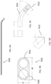
- FIG. 1 is a perspective view of an ablation device (102) and cinch device (130).
- the cinch device (130) may have a double-barrel configuration sized to allow the ablation device to pass through it.
- the ablation device (102) may be looped around a set of pulmonary veins (not shown in FIG. 1 ) and through the cinch device (130) such that the proximal and distal ends of the ablation device (102) may be disposed outside the body and generally adjacent to each other. That is, the ends of the ablation device (102) may be disposed proximal to the cinch device (130).
- the cinch device (130) may then be manipulated to tighten the loop formed by the ablation device (102) around the pulmonary veins to aid positioning of the ablation device for tissue ablation.
- the ablation device (102) may include a handle (104) coupled to a proximal portion of the ablation device (102) and a distal tip (101).
- the distal tip (101) may include an atraumatic shape to reduce trauma to tissue.
- the ablation device (102) may be configured to be slidably disposed within a first lumen (106) and a second lumen (131) of the cinch device (130).
- the first and second lumens (106, 131) may correspond to respective hollow tubular structures (e.g., first cinch catheter, second cinch catheter) that may be joined together along their length (L) to form a double-barreled or double lumen structure.
- the cinch device (130) may define a longitudinal axis.
- the ablation device (102) can include a series of fiducials or markings at its proximal and distal ends.
- a series of markings (112, 114) can be disposed on a distal section of the ablation device (102), and a series of markings (144, 146) can be disposed on a proximal section of the ablation device (102).
- these series of markings can be used to determine the electrodes (e.g., electrodes (108)) that are disposed inside or outside of the cinch device (130), as described in further detail with reference to FIGS. 2-5 .
- the spacing between markings (112, 114) can be set to correspond to a length of a group of electrodes and/or a distance between groups of electrodes.
- the length (L) of the cinch device (130) can be a multiple of such length and/or distance, to further facilitate determination of a number of electrodes or groups of electrodes inside or outside of the cinch device (130).
- the cinch device (130) may be sized and shaped for subxiphoid access.
- the cinch device (130) may include a curved distal portion, as described herein with respect to FIGS. 9A-9D .
- the ablation device (102) may have a diameter smaller than a diameter of the cinch device (130).
- the ablation device (102) may be introduced into a proximal end of first lumen (106) of the cinch device (130).
- the ablation device (102) may extend from a distal end of the first lumen (106) and be configured to form a loop.
- the ablation device (102) may include a central portion (124) having high flexibility (e.g., a flexible curvature).
- the ablation device (102) may then be introduced into a distal end of second lumen (131).
- the ablation device (102) may extend from a proximal end of the second lumen (131) such that the distal tip (101) of the ablation device (102) may be advanced out of the proximal end of the second lumen (131).
- the cinch device (130) may be sized to ensure that a suitable number of the electrodes (108) on the ablation device (102) may be drawn or pulled into each lumen (106, 131) of the cinch device (130).
- a desired length of the ablation device (102) may extend from a proximal end of the cinch device (130) for manipulation when the ablation device (102) forms a loop and is advanced through the cinch device (130).
- the cinch device (130) may have a length in the range between about 6 cm and about 30 cm, including all values and sub-ranges in-between.
- a distal portion of the ablation device e.g., distal to the electrodes (108)
- the ablation device (102) may include one or more electrodes (108) formed on a surface of the ablation device (102).
- a set of electrodes (108) are disposed along a central portion (124) of the ablation device (102).
- each electrode (108) may be independently addressable, while in other embodiments one or more subsets of electrodes (108) may be electrically wired together.
- a set of three or four adjacent electrodes may be electrically wired together as an electrode subset.
- non-adjacent electrodes may be electrically wired together.
- a spacing between successive electrodes and/or electrode subsets may vary.
- Each electrode (108) may include or be attached to an insulated electrical lead configured to sustain a voltage potential of at least about 700 V without dielectric breakdown of its corresponding insulation. In cases where more than one electrode is electrically wired together as an electrode group, a single such insulated lead may be connected to the electrode group.
- the electrodes (108) may have about the same size, shape, and/or spacing. In some embodiments, the size, shape, and spacing of the electrodes (108) may differ.
- the ablation device (102) may be configured for delivering a set of voltage pulse waveforms using a set of electrodes (108) to ablate tissue and electrically isolate one or more regions of the heart. At least a portion of the ablation device (102) may include a flexible curvature. For example, a central portion (124) of the ablation device (102) disposed between a proximal portion and a distal portion of the ablation device (102) may be flexible and configured to conform to a cardiac anatomy.
- the ablation device (102) may be configured to transform between a first configuration where the ablation device (102) is partially advanced into the cinch device (130) and a second configuration where the central portion (124) of the ablation device (102) forms a loop that may be configured to encircle tissue such as a pulmonary vein firmly. In this manner, the ablation device (102) and cinch device (130) may increase contact with heart tissue.
- a handle (104) may be coupled to the ablation device (102) to form a hub from which an electrical cable and/or connector (not shown) may be attached and for providing an entry point for guidewire introduction.
- the connector may connect directly or through an extension cable to a signal generator for delivery of voltage waveforms for pulsed electric field ablation.
- the handle (104) may include a guidewire lumen hub (not shown) for introduction of a guidewire that may provide mechanical support to the ablation device (102) when wrapped around tissue such as the pulmonary veins.
- the handle may define a flush port configured for flushing a guidewire lumen to aid introduction of a guidewire.
- the cinch device (130) may be positioned within the pericardial space at a location that allows access to the pulmonary veins for an ablation device (102) such as described herein.
- the ablation device (102) may be advanced through a first lumen (106) and looped around a set of pulmonary veins (e.g., four pulmonary veins). For example, pericardial reflections or folds in the pericardial membrane may be excised to allow the ablation device (102) to encircle all four pulmonary veins at the base of the trunk of the veins.
- the ablation device (102) may be advanced through the second lumen (131).
- the cinch device (130) may be advanced towards the heart, angled obliquely relative to the patient's chest, and placed on a posterior side of the heart.
- the proximal and distal ends of the ablation device (102) may be drawn through the cinch device (130) and pulled away from the heart to apply a predetermined amount of force to the pulmonary veins using the looped central portion (124) of the ablation device (102).
- the number of electrodes that may be drawn into the cinch device (130) when the ablation device (102) is tightened around the pulmonary veins may depend on the size of the left atrium and the amount of force applied. Any electrodes (108) disposed within a lumen of the cinch device (130) should not receive energy while the electrodes (108) looped around and in contact with the pulmonary veins. Electrodes (108) distal to a distal end of the cinch device (130) may be configured to receive ablation energy. Some embodiments described herein may provide a direct visual means to identify a location of a set of electrodes (108) of an ablation device (102) relative to the cinch device (130).
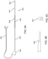
- FIG. 6A is a side view of an example, non-limiting ablation device (602).
- the ablation device (602) may include a catheter having a proximal portion (603), a central portion (624), and a distal portion (601).
- the proximal, distal, and central portions of the may each be composed of a compliant and/or flexible material to allow one or more portions of the ablation device (602) to easily conform to a cardiac anatomy.
- the distal portion (601) may include an atraumatic distal tip (605) such as shown in FIGS. 6B and 6C .
- the central portion (624) may include a set of electrodes (608) disposed on a surface of the ablation device (602).
- the set of electrodes (608) may include a plurality of subsets with each subset having a first length. Each subset of electrodes may be spaced apart from an adjacent subset by a second length. The second length may be greater than the first length.
- FIG. 6A shows the set of electrodes grouped into subsets of three electrodes each. Each electrode within a subset can have a third length. In some embodiments, one or more electrodes within a subset may have different lengths. For example, FIGS. 7A and 7B , described below, provide a more detailed view of subsets of three electrodes with varying lengths. Alternatively, each electrode within a subset may have the same length.
- a handle (604) may be coupled to the proximal portion (603) of the ablation device (602).
- a set of lead wires (640) may be coupled to the handle (604) and may be disposed within a lumen of the ablation device (602) to connect to the set of electrodes (608).
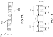
- FIGS. 7A and 7B are side views of a set of electrodes (708) of an example ablation device (702).
- the set of electrodes (708) may be disposed on a central portion (724) of the ablation device (702). As described herein, one or more sets of the electrodes (708) may not be used to deliver ablation energy such as when those electrodes are disposed within a lumen of a cinch device.
- the electrode subsets (730, 740) may have a first length (750) and may be separated by a second length (720).
- the electrodes may be formed of platinum-iridium material.
- the set of electrodes (708) may include a multiplicity of triplet subsets or groups where the electrodes (each in the form of rings) may have a third length in the range between about 1 mm and about 12 mm, including all values and sub-ranges in-between.
- Each electrode within a subset or group of electrodes (730, 740) may be separated by a fourth length (710).
- the number of electrode subsets may range between about 4 and about 20, including all values and sub-ranges in-between.
- FIG. 9A is a side view of a cinch device (930).
- the cinch device may include a distal portion having a curved portion (920) and a distal tip (910).
- the curved portion (920) may aid in positioning and advancement of an ablation device within a body cavity.
- FIG. 9B is a cross-sectional side view of a cinch device (930) having a first lumen (940) and a second lumen (950).
- the lumens (940, 950) may have the same diameter. The diameter can be about a diameter of an ablation catheter (not depicted) or larger such that it is designed for use therewith.
- FIGS. 9C and 9D are schematic side views of a distal end of a cinch device (930) including the curved portion (920) and distal tip (910).
- the cinch device (930) may be formed of Pebax (e.g., Pebax 40D).
- the distal tip (910) may have a length of between about 5 mm and about 25 mm, and may be composed of a material visible under fluoroscopy.
- the one or more portions of the cinch device (930) (e.g., the entire surface of the cinch device (930)) may be visible under fluoroscopy.
- the distal tip (910) may be atraumatic to reduce trauma to tissue.
- the curved portion (920) may have a curvature of between about 30 degrees and 60 degrees. For example, the curved portion (920) may have a curvature of about 45 degree.
- one or more of an ablation device and cinch device may include a set of fiducials that allow a surgeon and/or imaging system to determine a location of a set of electrodes of the ablation device relative to the cinch device.
- a set of markings disposed on one or more of a proximal portion and distal portion of the ablation device may correspond to the number of electrodes or electrode subsets within a lumen (e.g., inside) of the cinch device and/or the number of electrodes or electrode sets disposed outside of the cinch device.
- the electrodes or electrode subsets within the cinch device may be configured to be deactivated while the remaining electrodes or electrode sets that extend or that are exposed outside of the cinch device may be configured to deliver ablation energy to tissue such as a portion around a set of pulmonary veins of the heart.
- a fiducial corresponds to a mark, symbol (e.g., number, letter), geometric shape, hole, recession, protrusion, texture, combinations thereof, and the like disposed along a length of one or more of an ablation device and cinch device.
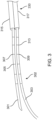
- FIG. 2 is a perspective view of an ablation device (202) and cinch device (230) where a proximal portion (203) of the ablation device (202) may be extended through a proximal end of a first lumen (219) of the cinch device (230).
- a distal portion (201) of the ablation device (202) may be extended through a proximal end of a second lumen (210) of the cinch device (230).
- the proximal portion (203) may include on its surface a first set of proximal fiducials (212) and a second set of proximal fiducials (214) disposed along its length.
- the first set of proximal fiducials (212) may be different (e.g., larger, wider) than the second set of proximal fiducials (214).
- Fiducials of the first and second set of proximal fiducials (212, 214) may be alternately disposed along a length of the ablation device (202). Adjacent fiducials of the first and second set of proximal fiducials (212, 214) may be spaced apart by a length of an electrode of the ablation device (202) (not shown in FIG. 2 ).
- the distal portion (201) may include on its surface a first set of distal fiducials (205) and a second set of distal fiducials (207) disposed along its length.
- the first set of distal fiducials (205) may be larger than the second set of distal fiducials (207). Fiducials of the first and second set of distal fiducials (205, 207) may be alternately disposed along a length of the ablation device (202). Adjacent fiducials of the first and second set of distal fiducials (205, 207) may be spaced apart by a length of an electrode. In some embodiments, the first and second sets of fiducials (205, 207, 212, 214) may be identified and differentiated by number, location, length, thickness, width, depth, shape, color, orientation, texture, material, combinations thereof, and the like.
- each subset of electrodes of the ablation device (202) may have a first length
- the length of the cinch device (230) may be an integer multiple of the sum of the first length and the distance between successive electrode groups (second length).
- the shorter markings may be adjacent to the larger markings with a spacing equal to a length of one electrode (e.g., length of the smallest electrode in each electrode subset, or a fifth length).
- the sets of fiducials disposed proximal to the cinch device (230) allow a surgeon to determine the number of electrodes disposed within the lumens of the cinch device (230) based on the number of sets of fiducials disposed proximal to the cinch device (230) (e.g., via visual confirmation, tactile confirmation, etc.).
- two electrode subsets may be disposed within the second lumen (210) (e.g., depending on a length of the second lumen (210)), and the majority of electrodes of a third electrode subset may be disposed distal to the cinch device (230) and exposed for delivery of ablation energy.
- the number of electrode subsets disposed within the lumens of the cinch device (230) and the number of electrode subsets disposed distal to and exposed outside of the lumens of the cinch device (230) can depend on, for example, a length of the lumens of the cinch device (230), a total number of electrode subsets, etc.
- FIG. 15 depicts a distal portion (1501) of an ablation device (1502) in a lumen (1503) (e.g., lumen, barrel) of a cinch device (1530).
- a lumen e.g., lumen, barrel
- First and second sets of fiducials (1505, 1507, 1511, 1513, 1515, 1517, 1519, 1520) having longer and shorter markings respectively, are shown distributed along a distal portion (1501) of the ablation device (1502).
- the other three fiducial pairs (1511, 1513), (1515, 1517) and (1519, 1520) are disposed inside the lumen (1503).
- a distal-most electrode subset of the ablation device (1502) may include a triplet of electrodes (1525, 1526, 1527). As depicted in FIG. 15 , a distal end (1522) and a proximal end (1523) of the distal-most electrode (1525) of the triplet are disposed within the lumen (1503) such that electrodes (1526, 1527) are exposed and distal to the lumen (1503) and may be configured for ablation energy delivery.
- the length of the lumen (1503) may be four times the spacing between the distal ends of successive electrode triplets (e.g., sum of a first length and a second length).
- This spacing r is the sum of the length p (first length) of an electrode triplet and the gap d (second length) between adjacent electrode triplets.
- the spacing between successive fiducial pairs (for example, the distance between larger fiducial (1511) and larger fiducial (1515)) may be configured as equal to the distance r between distal ends of successive electrode triplets.
- the lumen has a length that may be an integer multiple of the distance r (i.e., the distance between the distal ends of successive fiducials).
- fiducials (1505, 1507) exposed proximal to the lumen (1503) may visually confirm that a single electrode (in this example, the distal-most electrode (1525)) of the distal-most electrode triplet is disposed within the lumen (1503), while the rest of the electrodes (1526, 1527) of that electrode triplet are exposed distal to the lumen (1503).
- fiducial configurations may enable other estimations.
- sets of fiducials may be used, with each fiducial set to replicate, represent, and/or otherwise correspond an electrode group (e.g., the electrode triplet in the above example).
- the number of electrodes disposed within the lumen of a cinch device tube, as well as which electrodes of the most distal-most exposed electrode group are disposed within the lumen of the cinch device may be visually confirmed, since a corresponding number of fiducial sets would be visible on the distal portion of the ablation proximal to the cinch device.
- a single fiducial may be separated successively by a length (e.g., distance r ) corresponding to the distance between distal ends of successive electrode groups.
- the number of fiducials visible on the distal portion of an ablation device outside the cinch device may correspond to the number of electrode groups that are disposed within a lumen of the cinch device.
- each electrode within a group can have the same length (e.g., as depicted in FIG. 15 ), while in other embodiments, electrodes within a group can have different lengths (e.g., as depicted in FIGS. 7A and 7B ).
- FIG. 3 is a perspective view of an ablation device (302) and cinch device (330) where a proximal portion (303) of the ablation device (302) may be extended through a proximal end of a first lumen (317) of the cinch device (330).
- a distal portion (301) of the ablation device (302) may be extended through a proximal end of a second lumen (315) of the cinch device (330).
- the proximal portion (303) may include on its surface a set of proximal fiducials (309, 313) (e.g., markings) disposed along its length.
- the distal portion (301) may include on its surface a set of distal fiducials (305, 307) (e.g., markings) disposed along its length.
- the proximal and distal set of fiducials may be identified and differentiated by one or more characteristics including number, location, length, thickness, width, depth, spacing, shape, color, pattern, orientation, texture, material, combinations thereof, and the like.
- the set of fiducials disposed proximal to the cinch device (330) allow a surgeon to determine the number of electrodes disposed within the lumens of the cinch device (330) based on the number of fiducials disposed proximal to the cinch device (330) determined based on visual confirmation, tactile confirmation, and/or other types of confirmation. For example, if four complete fiducials disposed along the distal portion (301) of the ablation device (302) are visible outside the cinch device (330), then three electrode subsets may be disposed within the second lumen (315) of the cinch device (330).
- a fourth electrode group may be determined to be either inside the cinch device (330) or exposed outside the cinch device (330), respectively.
- the number of electrode subsets disposed within the first lumen (317) of the cinch device (330) may be determined using the exposed fiducials (e.g., visual, tactile, etc.) disposed along the length of the proximal portion (303) of the ablation device (302) proximal to the cinch device (302).
- two electrode subsets may be determined to be disposed within the first lumen (317) of the cinch device (330) based on the number of visible fiducials along the proximal portion (303).
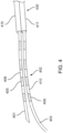
- FIG. 4 is a perspective view of an ablation device (402) and cinch device (430) where a proximal portion (403) of the ablation device (402) may be extended through a proximal end of a first lumen (417) of the cinch device (430).
- the ablation device (402) can be similar to other ablation devices described herein, but have fiducials implemented as alternating dark and light bands.
- a distal portion (401) of the ablation device (402) may be extended through a proximal end of a second lumen (415) of the cinch device (430).
- the proximal portion (403) may include on its surface a set of proximal fiducials (409, 410) (e.g., alternating dark and light bands) disposed along its length
- the distal portion (401) may include on its surface a set of distal fiducials (405, 406) (e.g., alternating dark and light bands) disposed along its length.
- the proximal and distal set of fiducials may be identified and differentiated by number, location, length, thickness, spacing, width, depth, shape, color, pattern, orientation, texture, combinations thereof, and the like.
- each subset of electrodes of the ablation device (402) may have the same length, and the length of the cinch device may be an integer multiple of the sum of the electrode subset length and the distance between successive electrode groups.
- the set of fiducials disposed outside the cinch device (430) allow a surgeon to determine the number of electrodes disposed within the lumens of the cinch device (430) based on the number of fiducials disposed outside the cinch device (430) that can be determined using visual, tactile, etc. confirmation. For example, if four complete sets of bands disposed along the distal portion (401) of the ablation device (402) are visible proximal to the cinch device (430), then at least three electrode subsets may be disposed within the second lumen (415) of the cinch device (430).
- a fourth electrode group may be determined to be either inside the cinch device (430) or exposed outside the cinch device (430), respectively.
- the number of electrode subsets disposed within the first lumen (417) of the cinch device (430) may be determined using the visible fiducials disposed along the length of the proximal portion (403) of the ablation device (402) proximal to the cinch device (402). For example, two electrode subsets may be determined to be disposed within the first lumen (417) of the cinch device (430) based on the number of visible fiducials along the proximal portion (403).
- a signal generator may be configured to deliver energy to the exposed electrodes looped around the pulmonary veins without delivering energy to electrodes within the cinch device (430). For example, a user may enter fiducial information into a user interface of the signal generator.
- FIG. 5 is a perspective view of a cinch device (530) including a first lumen (501) (e.g., proximal tube) and a second lumen (500) (e.g., distal tube).
- the first and second lumens (501, 500) may include on its surface a set of fiducials (503, 505, 507, 512, 513) disposed along its length adjacent to a proximal end (510) of the cinch device (530).
- the set of fiducials may be identified and differentiated by number, location, length, thickness, width, depth, shape, color, pattern, orientation, texture, material, combinations thereof, and the like.
- a distance from third fiducial (507) to fourth fiducial (512) may correspond to a distance or separation between the second electrode and the third electrode of an electrode subset of three electrodes. In some embodiments, a distance from fourth fiducial (512) to fifth fiducial (513) may be equal to a length of the third electrode of an electrode subset of three electrodes.
- the set of fiducials on each lumen of the cinch device (530) may correspond to an electrode triplet of an ablation device configured to extend through the cinch device (530).
- the ablation device may be held in place using a clip (e.g., a surgical clip) at a proximal end of the cinch device, surgical tape, combinations thereof, and the like.
- a locking mechanism may be engaged after a predetermined number of electrodes of an electrode group are disposed distal to a cinch device (e.g., majority of electrodes of an electrode subset are deployed outside of a distal end of a first and second lumen of the cinch device).
- the electrodes disposed along the ablation device in a loop may be firmly positioned around a set of four pulmonary veins.
- Pulsed electric field ablation energy may be delivered to suitable electrode sets or pairings (e.g., exposed electrodes around the loop) in order to rapidly ablate tissue around the pulmonary veins (e.g., create a box lesion).
- This method of delivering a box lesion may be useful, for example, as a therapeutic treatment for one or more cardiac arrhythmia conditions such as atrial fibrillation.
- Pulsed electric field voltage pulses with a suitable voltage level may be delivered in the form of a suitable waveform as described herein.
- the waveforms may have a hierarchical structure with a multiplicity of levels of hierarchy as suitable for efficient and effective therapy delivery.
- a signal generator may be configured to deliver a set of pulse waveforms to the ablation device.
- the start of ablation delivery may occur in timed synchrony with a set of pacing pulses (e.g., during refractory periods associated with the set of pacing pulses).
- the electrodes as described may be composed of any suitable biocompatible conductive material including, but not limited to, one or more of silver, palladium, stainless steel, platinum, titanium, platinum-iridium alloys, gold, copper, nickel, combinations thereof, and the like.
- the electrode materials may be plated, coated, and/or otherwise applied in an appropriately thick layer on top of a different substrate material.
- electrode portions may be coupled using annealing, soldering, welding, crimping, lamination, combinations thereof, and the like.
- the spline, loop, and body of the ablation devices disclosed may be composed of any suitable biocompatible material including metals, glasses, ceramics, polymers, combinations thereof, and the like.
- the catheter shaft may be made of a flexible polymeric material such as Teflon, Nylon, Pebax, combinations thereof, and the like.
- An ablation device may be introduced into an epicardial space.
- the ablation catheter may be advanced through a cinch device and looped around cardiac tissue such as a set of pulmonary veins.
- the distal end of the ablation catheter may be advanced back through the cinch device such that the ends of the ablation catheter may be pulled away from the cinch device such that the loop of the ablation catheter tightens around the tissue to increase contact and apply a predetermined force.
- a position of the ablation catheter relative to the cinch device may be verified using a set of fiducials disposed on the ablation catheter and/or cinch device.
- Energy delivery to a set of electrodes of the ablation catheter may be based on the electrodes identified using the fiducials. For example, a pulse waveform may be generated and delivered to one or more identified electrodes of the ablation catheter (e.g., electrodes exposed outside the cinch device) to ablate tissue.
- a pulse waveform may be generated and delivered to one or more identified electrodes of the ablation catheter (e.g., electrodes exposed outside the cinch device) to ablate tissue.
- the methods described here include introducing and disposing an ablation device through a cinch device and looped around one or more pulmonary veins.
- the cinch device may be positioned and the ends of the ablation device may be drawn through the cinch device such that the loop formed by the ablation device is tightened around a set of pulmonary veins to ablate.
- the position of the ablation device relative to the cinch device may be locked in place.
- a pulse waveform may be delivered by one or more electrodes of the ablation device to ablate tissue.
- the pulse waveforms may include a set of levels of a hierarchy to reduce total energy delivery. It should be appreciated that any of the ablation devices described herein may be used to ablate tissue using the methods discussed below as appropriate.
- a system can include one or more ablation devices (e.g., an ablation device as illustrated and described with respect to FIGS. 1-7 , 14 , and 15 ) useful for ablating tissue.
- FIG. 16 is a flowchart (1600) of an example method of a tissue ablation process.
- a distal end of a first device may be advanced into a proximal end of a first lumen of a second device (e.g., cinch device), at (1604).
- the first device e.g., ablation device, such as the ablation device (102) may be any of the ablation devices (15, 102, 202, 302, 402, 602, 702, 840, 1501) described herein.
- the first device may be advanced through the first lumen and out from a distal end of the first lumen of the cinch device, at (1606).
- the first device may be looped around tissue of the patient, at (1608).
- the ablation device may extend from a distal end of the cinch device and be looped around tissue, such as a set of four pulmonary veins, at the base of the trunk of the veins.
- pericardial reflections or folds in the pericardial membrane may be excised to permit such looping.
- the first device may be advanced back into the first device through a proximal end of a second lumen, at (1610). A portion of the first device may be disposed in the first lumen while a more distal portion of the first device is disposed and/or advanced into the second lumen of the second device. The first device may be advanced through the second lumen and out from a proximal end of the second lumen of the cinch device, at (1612). A proximal and distal end of the ablation device may extend from a proximal end of the cinch device. The cinch device may be angled obliquely with respect to the patient chest.
- the proximal and distal ends of the first device may be advanced away from a proximal end of the second device, at (1614).
- the proximal and distal ends of the ablation device are drawn through the cinch device until the loop of the ablation device contacts and firmly encircles all the pulmonary veins.
- the loop formed by a central portion of the ablation device may bend (e.g., form a noose) around the pulmonary veins.
- the ablation device may first be looped around the set of four pulmonary veins and then the proximal and distal ends of the ablation device may be advanced through the two lumens of the cinch device.
- the cinch device may be advanced over the ablation device in a distal direction towards the heart after the ablation device is looped around tissue.
- a user may draw the ablation device away a predetermined amount to increase contact between the ablation device and tissue and/or to apply a predetermined amount of force from the ablation device to the tissue.
- one or more of the electrodes of the ablation device may be drawn into the cinch device as the loop is tightened around the pulmonary veins. The electrodes exposed on the loop may be used to deliver ablation energy to tissue.
- a guidewire may be positioned around cardiac tissue (e.g., one or more pulmonary veins of the heart), using procedures and methods as described in the '394 PCT Application Publication.
- the ends of the guidewire may be placed within the second device (e.g., the cinch device), and then the first device (e.g., the ablation device) may be passed over the guidewire such that its distal end is advanced through the proximal end of the first lumen of the second device, at (1604).
- a distal end of the second device prior to advancing the first device through the second device, at (1604), can be advanced into an open pericardial space of a patient at a location that permits access to the posterior section of the left atrium.
- the distal end of the second device may be advanced into the open pericardial space. While the distal end of the second device can be advanced into the pericardial space, the proximal end of the second device can remain external to the heart and/or the patient.
- the process may proceed from (1614) to the flowchart (1700) of FIG. 17 described in more detail herein, where a user (e.g., surgeon) may view one or more sets of fiducials on one or more of the ablation device and cinch device to determine the location of the electrodes relative to the cinch device (e.g., number of electrodes within the first and second lumens of the cinch device).
- a position of the first device may be locked relative to the second device, at (1618).
- the set of electrodes may be configured in a set of anode-cathode pairings.
- the electrodes or an appropriate sequence of paired anode-cathode subsets of electrodes may be electrically activated in a sequential manner to deliver a pulse waveform with each anode-cathode pairing.
- the set of electrodes may be activated sequentially in a clockwise or counter-clockwise manner.
- the cathode electrodes may be activated sequentially along with respective sequential anode electrodes activation until ablation is completed.
- the electrodes may be activated all at once or in a predetermined sequence.
- the pulse waveform may include a first level of a hierarchy of the pulse waveform including a first set of pulses. Each pulse has a pulse time duration and a first time interval separating successive pulses.
- a second level of the hierarchy of the pulse waveform may include a plurality of first sets of pulses as a second set of pulses.
- a second time interval may separate successive first sets of pulses.
- the second time interval may be at least three times the duration of the first time interval.
- a third level of the hierarchy of the pulse waveform may include a plurality of second sets of pulses as a third set of pulses.
- a third time interval may separate successive second sets of pulses.
- the third time interval may be at least thirty times the duration of the second level time interval.
- a voltage pulse waveform having a hierarchical structure may be applied across different anode-cathode subsets (optionally with a time delay).
- the generated pulse waveform may be delivered to tissue.
- a contiguous, transmural zone of ablated tissue may electrically isolate the pulmonary vein from a main body of the left atrium.
- the pulse waveform(s) as disclosed herein are usable with any of the systems (800), devices (e.g., 102, 202, 302, 402, 502, 602, 702, 840), and methods described herein. Some embodiments are directed to pulsed high voltage waveforms together with a sequenced delivery scheme for delivering energy to tissue via sets of electrodes. In some embodiments, peak electric field values can be reduced and/or minimized while at the same time sufficiently large electric field magnitudes can be maintained in regions where tissue ablation is desired.
- a system useful for irreversible electroporation includes a signal generator and a processor capable of being configured to apply pulsed voltage waveforms to a selected plurality or a subset of electrodes of an ablation device.
- the processor is configured to control inputs whereby selected pairs of anode-cathode subsets of electrodes can be sequentially triggered based on a pre-determined sequence.
- the pulsed voltage waveforms disclosed herein are hierarchical in organization and have a nested structure.
- the pulsed waveform includes hierarchical groupings of pulses with a variety of associated timescales.
- the associated timescales and pulse widths, and the numbers of pulses and hierarchical groupings can be selected so as to satisfy one or more of a set of Diophantine inequalities.
- Pulsed waveforms for electroporation energy delivery as disclosed herein may enhance the safety, efficiency and effectiveness of the energy delivery by reducing the electric field threshold associated with irreversible electroporation, yielding more effective ablative lesions with reduced total energy delivered.
- the height of each pulse (1000) or the voltage amplitude of the pulse (1000) can be in the range from about 400 volts, about 1,000 volts, about 5,000 volts, about 10,000 volts, about 15,000 volts, including all values and sub ranges in between.
- the pulse (1000) is separated from a neighboring pulse by a time interval (1002), also sometimes referred to as a first time interval.
- FIG. 12 further elaborates the structure of a nested pulse hierarchy waveform.
- a series of m 1 pulses (individual pulses not shown) form a group of pulses (1200) (e.g., a first set of pulses).
- a series of m 2 such groups separated by an inter-group time interval (1210) of duration t 2 (e.g., a second time interval) between one group and the next form a packet (e.g., a second set of pulses).
- FIG. 13 provides an example of a biphasic waveform sequence with a hierarchical structure.
- biphasic pulses such as (1300) have a positive voltage portion as well as a negative voltage portion to complete one cycle of the pulse.
- There is a time delay (1302) e.g., a first time interval
- n 1 such cycles form a group of pulses (1310) (e.g., a first set of pulses).
- a series of n 2 such groups separated by an inter-group time interval (1312) (e.g., a second time interval) of duration t 2 between one group and the next form a packet (1320) (e.g., a second set of pulses).
- the total time duration of the third set of pulses can be between about 60 microseconds and about 200 milliseconds, including all values and sub ranges in between.
- the generally iterative or nested structure of the waveforms can continue to a higher plurality of levels, such as ten levels of structure, or more.
- the terms “about” and/or “approximately” when used in conjunction with numerical values and/or ranges generally refer to those numerical values and/or ranges near to a recited numerical value and/or range. In some instances, the terms “about” and “approximately” may mean within ⁇ 10% of the recited value. For example, in some instances, “about 100 [units]” may mean within ⁇ 10% of 100 (e.g., from 90 to 110). The terms “about” and “approximately” may be used interchangeably.
- a member is intended to mean a single member or a combination of members
- a material is intended to mean one or more materials
- a processor is intended to mean a single processor or multiple processors
- memory is intended to mean one or more memories, or a combination thereof.
Landscapes
- Health & Medical Sciences (AREA)
- Life Sciences & Earth Sciences (AREA)
- Surgery (AREA)
- Engineering & Computer Science (AREA)
- Plasma & Fusion (AREA)
- Medical Informatics (AREA)
- Otolaryngology (AREA)
- Physics & Mathematics (AREA)
- Cardiology (AREA)
- Biomedical Technology (AREA)
- Heart & Thoracic Surgery (AREA)
- Nuclear Medicine, Radiotherapy & Molecular Imaging (AREA)
- Molecular Biology (AREA)
- Animal Behavior & Ethology (AREA)
- General Health & Medical Sciences (AREA)
- Public Health (AREA)
- Veterinary Medicine (AREA)
- Surgical Instruments (AREA)
Priority Applications (1)
| Application Number | Priority Date | Filing Date | Title |
|---|---|---|---|
| EP24170082.2A EP4410228A3 (en) | 2018-05-07 | 2019-05-06 | Epicardial ablation catheter |
Applications Claiming Priority (2)
| Application Number | Priority Date | Filing Date | Title |
|---|---|---|---|
| US201862667964P | 2018-05-07 | 2018-05-07 | |
| PCT/US2019/030882 WO2019217300A1 (en) | 2018-05-07 | 2019-05-06 | Epicardial ablation catheter |
Related Child Applications (2)
| Application Number | Title | Priority Date | Filing Date |
|---|---|---|---|
| EP24170082.2A Division EP4410228A3 (en) | 2018-05-07 | 2019-05-06 | Epicardial ablation catheter |
| EP24170082.2A Division-Into EP4410228A3 (en) | 2018-05-07 | 2019-05-06 | Epicardial ablation catheter |
Publications (2)
| Publication Number | Publication Date |
|---|---|
| EP3790485A1 EP3790485A1 (en) | 2021-03-17 |
| EP3790485B1 true EP3790485B1 (en) | 2024-06-26 |
Family
ID=66625291
Family Applications (2)
| Application Number | Title | Priority Date | Filing Date |
|---|---|---|---|
| EP19725482.4A Active EP3790485B1 (en) | 2018-05-07 | 2019-05-06 | Epicardial ablation catheter |
| EP24170082.2A Pending EP4410228A3 (en) | 2018-05-07 | 2019-05-06 | Epicardial ablation catheter |
Family Applications After (1)
| Application Number | Title | Priority Date | Filing Date |
|---|---|---|---|
| EP24170082.2A Pending EP4410228A3 (en) | 2018-05-07 | 2019-05-06 | Epicardial ablation catheter |
Country Status (5)
| Country | Link |
|---|---|
| US (2) | US11020180B2 (https=) |
| EP (2) | EP3790485B1 (https=) |
| JP (2) | JP7399881B2 (https=) |
| CN (2) | CN116327352A (https=) |
| WO (1) | WO2019217300A1 (https=) |
Families Citing this family (11)
| Publication number | Priority date | Publication date | Assignee | Title |
|---|---|---|---|---|
| JP6941030B2 (ja) * | 2017-11-08 | 2021-09-29 | 日本光電工業株式会社 | 電極カテーテル |
| US20190336198A1 (en) | 2018-05-03 | 2019-11-07 | Farapulse, Inc. | Systems, devices, and methods for ablation using surgical clamps |
| CN116327352A (zh) | 2018-05-07 | 2023-06-27 | 波士顿科学医学有限公司 | 心外膜消融导管 |
| US12102374B2 (en) * | 2019-12-03 | 2024-10-01 | Biosense Webster (Israel) Ltd. | Pulse generator for irreversible electroporation with switchable pulse application |
| US12076071B2 (en) | 2020-08-14 | 2024-09-03 | Kardium Inc. | Systems and methods for treating tissue with pulsed field ablation |
| KR102868326B1 (ko) | 2021-04-07 | 2025-10-13 | 비티엘 메디컬 디벨롭먼트 에이.에스. | 펄스 필드 절제 디바이스 및 방법 |
| IL291970B2 (en) * | 2021-04-13 | 2025-09-01 | Biosense Webster Israel Ltd | Pulse generator for non-invasive electroporation with switchable pulse application |
| HRP20250794T1 (hr) | 2021-07-06 | 2025-08-29 | Btl Medical Development A.S. | Uređaj za ablaciju pulsnim poljem |
| US20230051310A1 (en) * | 2021-08-16 | 2023-02-16 | Biosense Webster (Israel) Ltd. | Phrenic nerve warning |
| US20230067388A1 (en) * | 2021-08-24 | 2023-03-02 | Intelligent Implants Limited | System for a dynamic electrically stimulating rod-like orthopedic implant |
| CR20250188A (es) | 2022-10-05 | 2025-08-22 | Btl Medical Dev A S | Dispositivo y método de ablación de campo pulsado |
Family Cites Families (570)
| Publication number | Priority date | Publication date | Assignee | Title |
|---|---|---|---|---|
| US4200104A (en) | 1977-11-17 | 1980-04-29 | Valleylab, Inc. | Contact area measurement apparatus for use in electrosurgery |
| US4470407A (en) | 1982-03-11 | 1984-09-11 | Laserscope, Inc. | Endoscopic device |
| US4739759A (en) | 1985-02-26 | 1988-04-26 | Concept, Inc. | Microprocessor controlled electrosurgical generator |
| US5547467A (en) | 1988-01-21 | 1996-08-20 | Massachusettes Institute Of Technology | Method for rapid temporal control of molecular transport across tissue |
| US5344435A (en) | 1988-07-28 | 1994-09-06 | Bsd Medical Corporation | Urethral inserted applicator prostate hyperthermia |
| FR2639238B1 (fr) | 1988-11-21 | 1991-02-22 | Technomed Int Sa | Appareil de traitement chirurgical de tissus par hyperthermie, de preference la prostate, comprenant des moyens de protection thermique comprenant de preference des moyens formant ecran radioreflechissant |
| US5257635A (en) | 1988-11-25 | 1993-11-02 | Sensor Electronics, Inc. | Electrical heating catheter |
| US5749914A (en) | 1989-01-06 | 1998-05-12 | Advanced Coronary Intervention | Catheter for obstructed stent |
| US5342301A (en) | 1992-08-13 | 1994-08-30 | Advanced Polymers Incorporated | Multi-lumen balloons and catheters made therewith |
| AU1899292A (en) | 1991-05-24 | 1993-01-08 | Ep Technologies Inc | Combination monophasic action potential/ablation catheter and high-performance filter system |
| US6029671A (en) | 1991-07-16 | 2000-02-29 | Heartport, Inc. | System and methods for performing endovascular procedures |
| US5697281A (en) | 1991-10-09 | 1997-12-16 | Arthrocare Corporation | System and method for electrosurgical cutting and ablation |
| US5524338A (en) | 1991-10-22 | 1996-06-11 | Pi Medical Corporation | Method of making implantable microelectrode |
| US5304214A (en) | 1992-01-21 | 1994-04-19 | Med Institute, Inc. | Transurethral ablation catheter |
| US5306296A (en) | 1992-08-21 | 1994-04-26 | Medtronic, Inc. | Annuloplasty and suture rings |
| US5242441A (en) | 1992-02-24 | 1993-09-07 | Boaz Avitall | Deflectable catheter with rotatable tip electrode |
| US5281213A (en) | 1992-04-16 | 1994-01-25 | Implemed, Inc. | Catheter for ice mapping and ablation |
| US5443463A (en) | 1992-05-01 | 1995-08-22 | Vesta Medical, Inc. | Coagulating forceps |
| US20050222632A1 (en) | 1992-05-17 | 2005-10-06 | Obino Stan F | Device and method for the treatment of cardiac disorders |
| US5341807A (en) | 1992-06-30 | 1994-08-30 | American Cardiac Ablation Co., Inc. | Ablation catheter positioning system |
| US5313943A (en) | 1992-09-25 | 1994-05-24 | Ep Technologies, Inc. | Catheters and methods for performing cardiac diagnosis and treatment |
| US5700243A (en) | 1992-10-30 | 1997-12-23 | Pdt Systems, Inc. | Balloon perfusion catheter |
| US6068653A (en) | 1992-11-13 | 2000-05-30 | Scimed Life Systems, Inc. | Electrophysiology catheter device |
| US5334193A (en) | 1992-11-13 | 1994-08-02 | American Cardiac Ablation Co., Inc. | Fluid cooled ablation catheter |
| US5545161A (en) | 1992-12-01 | 1996-08-13 | Cardiac Pathways Corporation | Catheter for RF ablation having cooled electrode with electrically insulated sleeve |
| US6749604B1 (en) | 1993-05-10 | 2004-06-15 | Arthrocare Corporation | Electrosurgical instrument with axially-spaced electrodes |
| US5531685A (en) | 1993-06-11 | 1996-07-02 | Catheter Research, Inc. | Steerable variable stiffness device |
| FR2708860B1 (fr) | 1993-08-11 | 1995-10-13 | Ela Medical Sa | Circuit de protection pour dispositif électronique implantable. |
| US5545193A (en) | 1993-10-15 | 1996-08-13 | Ep Technologies, Inc. | Helically wound radio-frequency emitting electrodes for creating lesions in body tissue |
| US5722400A (en) | 1995-02-16 | 1998-03-03 | Daig Corporation | Guiding introducers for use in the treatment of left ventricular tachycardia |
| US5921924A (en) | 1993-12-03 | 1999-07-13 | Avitall; Boaz | Mapping and ablation catheter system utilizing multiple control elements |
| US5454370A (en) | 1993-12-03 | 1995-10-03 | Avitall; Boaz | Mapping and ablation electrode configuration |
| US5928269A (en) | 1994-04-04 | 1999-07-27 | Alt; Eckhard | Apparatus and method for temporary atrial defibrillation with external defibrillator and implanted transvenous catheter and electrodes |
| US5578040A (en) | 1994-06-14 | 1996-11-26 | Smith; Albert C. | Ocular repair system and apparatus |
| US5617854A (en) | 1994-06-22 | 1997-04-08 | Munsif; Anand | Shaped catheter device and method |
| US5836947A (en) | 1994-10-07 | 1998-11-17 | Ep Technologies, Inc. | Flexible structures having movable splines for supporting electrode elements |
| US6071274A (en) | 1996-12-19 | 2000-06-06 | Ep Technologies, Inc. | Loop structures for supporting multiple electrode elements |
| US5885278A (en) * | 1994-10-07 | 1999-03-23 | E.P. Technologies, Inc. | Structures for deploying movable electrode elements |
| US5722402A (en) | 1994-10-11 | 1998-03-03 | Ep Technologies, Inc. | Systems and methods for guiding movable electrode elements within multiple-electrode structures |
| US5876336A (en) | 1994-10-11 | 1999-03-02 | Ep Technologies, Inc. | Systems and methods for guiding movable electrode elements within multiple-electrode structure |
| US5624430A (en) | 1994-11-28 | 1997-04-29 | Eton; Darwin | Magnetic device to assist transcorporeal guidewire placement |
| US5647871A (en) | 1995-03-10 | 1997-07-15 | Microsurge, Inc. | Electrosurgery with cooled electrodes |
| US5810762A (en) | 1995-04-10 | 1998-09-22 | Genetronics, Inc. | Electroporation system with voltage control feedback for clinical applications |
| US6090104A (en) | 1995-06-07 | 2000-07-18 | Cordis Webster, Inc. | Catheter with a spirally wound flat ribbon electrode |
| US20060024359A1 (en) | 1995-06-07 | 2006-02-02 | Walker Jeffrey P | Drug delivery system and method |
| US5702438A (en) | 1995-06-08 | 1997-12-30 | Avitall; Boaz | Expandable recording and ablation catheter system |
| US5788692A (en) | 1995-06-30 | 1998-08-04 | Fidus Medical Technology Corporation | Mapping ablation catheter |
| US6023638A (en) | 1995-07-28 | 2000-02-08 | Scimed Life Systems, Inc. | System and method for conducting electrophysiological testing using high-voltage energy pulses to stun tissue |
| US5706823A (en) | 1995-08-18 | 1998-01-13 | Quinton Instrument Company | Electrophysiology filtering system |
| DE69631681T2 (de) | 1995-10-06 | 2004-07-29 | Cordis Webster, Inc., Diamond Bar | Elektroden-katheter mit geteilter spitze |
| DE29519651U1 (de) | 1995-12-14 | 1996-02-01 | Muntermann, Axel, 35583 Wetzlar | Vorrichtung zur linienförmigen Radiofrequenz-Katheterablation endomyokardialen Gewebes |
| BR9612395A (pt) | 1995-12-29 | 1999-07-13 | Gyrus Medical Ltd | Instrumento eletrocirúrgico e um conjunto de eltrodo eletrocirúrgico |
| US7141049B2 (en) | 1999-03-09 | 2006-11-28 | Thermage, Inc. | Handpiece for treatment of tissue |
| WO1997025917A1 (en) | 1996-01-19 | 1997-07-24 | Ep Technologies, Inc. | Multi-function electrode structures for electrically analyzing and heating body tissue |
| US5868736A (en) | 1996-04-12 | 1999-02-09 | Ep Technologies, Inc. | Systems and methods to control tissue heating or ablation with porous electrode structures |
| US5836874A (en) | 1996-04-08 | 1998-11-17 | Ep Technologies, Inc. | Multi-function electrode structures for electrically analyzing and heating body tissue |
| US5800482A (en) | 1996-03-06 | 1998-09-01 | Cardiac Pathways Corporation | Apparatus and method for linear lesion ablation |
| US5830224A (en) | 1996-03-15 | 1998-11-03 | Beth Israel Deaconess Medical Center | Catheter apparatus and methodology for generating a fistula on-demand between closely associated blood vessels at a pre-chosen anatomic site in-vivo |
| US5779699A (en) | 1996-03-29 | 1998-07-14 | Medtronic, Inc. | Slip resistant field focusing ablation catheter electrode |
| US5836942A (en) | 1996-04-04 | 1998-11-17 | Minnesota Mining And Manufacturing Company | Biomedical electrode with lossy dielectric properties |
| US5863291A (en) | 1996-04-08 | 1999-01-26 | Cardima, Inc. | Linear ablation assembly |
| US5904709A (en) | 1996-04-17 | 1999-05-18 | The United States Of America As Represented By The Administrator Of The National Aeronautics And Space Administration | Microwave treatment for cardiac arrhythmias |
| US5672170A (en) | 1996-06-20 | 1997-09-30 | Cynosure, Inc. | Laser transmyocardial revascularization arrangement |
| US6006131A (en) | 1996-08-13 | 1999-12-21 | Uab Research Foundation | Dual current pathway atrial defibrillation apparatus |
| DE59610941D1 (de) | 1996-09-27 | 2004-04-22 | Sulzer Osypka Gmbh | Einrichtung zur Durchführung von diagnostischen und/oder therapeutischen Herzeingriffen mit Katheter |
| US6464697B1 (en) | 1998-02-19 | 2002-10-15 | Curon Medical, Inc. | Stomach and adjoining tissue regions in the esophagus |
| US6805128B1 (en) | 1996-10-22 | 2004-10-19 | Epicor Medical, Inc. | Apparatus and method for ablating tissue |
| US7052493B2 (en) | 1996-10-22 | 2006-05-30 | Epicor Medical, Inc. | Methods and devices for ablation |
| US6311692B1 (en) | 1996-10-22 | 2001-11-06 | Epicor, Inc. | Apparatus and method for diagnosis and therapy of electrophysiological disease |
| US6096036A (en) | 1998-05-05 | 2000-08-01 | Cardiac Pacemakers, Inc. | Steerable catheter with preformed distal shape and method for use |
| US6002955A (en) | 1996-11-08 | 1999-12-14 | Medtronic, Inc. | Stabilized electrophysiology catheter and method for use |
| US6035238A (en) | 1997-08-13 | 2000-03-07 | Surx, Inc. | Noninvasive devices, methods, and systems for shrinking of tissues |
| US6076012A (en) * | 1996-12-19 | 2000-06-13 | Ep Technologies, Inc. | Structures for supporting porous electrode elements |
| US5913854A (en) | 1997-02-04 | 1999-06-22 | Medtronic, Inc. | Fluid cooled ablation catheter and method for making |
| US5916213A (en) | 1997-02-04 | 1999-06-29 | Medtronic, Inc. | Systems and methods for tissue mapping and ablation |
| US6039757A (en) | 1997-03-12 | 2000-03-21 | Cardiosynopsis, Inc. | In situ formed fenestrated stent |
| US6223085B1 (en) | 1997-05-06 | 2001-04-24 | Urologix, Inc. | Device and method for preventing restenosis |
| US6012457A (en) | 1997-07-08 | 2000-01-11 | The Regents Of The University Of California | Device and method for forming a circumferential conduction block in a pulmonary vein |
| US5849028A (en) | 1997-05-16 | 1998-12-15 | Irvine Biomedical, Inc. | Catheter and method for radiofrequency ablation of cardiac tissue |
| US5978704A (en) | 1997-06-03 | 1999-11-02 | Uab Research Foundation | Method and apparatus for treating cardiac arrhythmia |
| US5938660A (en) | 1997-06-27 | 1999-08-17 | Daig Corporation | Process and device for the treatment of atrial arrhythmia |
| CA2294927C (en) | 1997-07-08 | 2008-09-23 | The Regents Of The University Of California | Circumferential ablation device assembly and method |
| US6966908B2 (en) | 1997-07-08 | 2005-11-22 | Atrionix, Inc. | Tissue ablation device assembly and method for electrically isolating a pulmonary vein ostium from an atrial wall |
| US6245064B1 (en) | 1997-07-08 | 2001-06-12 | Atrionix, Inc. | Circumferential ablation device assembly |
| US6164283A (en) | 1997-07-08 | 2000-12-26 | The Regents Of The University Of California | Device and method for forming a circumferential conduction block in a pulmonary vein |
| US6009351A (en) | 1997-07-14 | 1999-12-28 | Urologix, Inc. | System and method for transurethral heating with rectal cooling |
| US6014579A (en) | 1997-07-21 | 2000-01-11 | Cardiac Pathways Corp. | Endocardial mapping catheter with movable electrode |
| JP2002512552A (ja) | 1997-07-22 | 2002-04-23 | イーメッド コーポレイション | 心臓組織中への薬剤のイオン電気導入法による配送 |
| US6216034B1 (en) | 1997-08-01 | 2001-04-10 | Genetronics, Inc. | Method of programming an array of needle electrodes for electroporation therapy of tissue |
| US5895404A (en) | 1997-09-29 | 1999-04-20 | Ruiz; Carlos E. | Apparatus and methods for percutaneously forming a passageway between adjacent vessels or portions of a vessel |
| US6464699B1 (en) | 1997-10-10 | 2002-10-15 | Scimed Life Systems, Inc. | Method and apparatus for positioning a diagnostic or therapeutic element on body tissue and mask element for use with same |
| US6645200B1 (en) | 1997-10-10 | 2003-11-11 | Scimed Life Systems, Inc. | Method and apparatus for positioning a diagnostic or therapeutic element within the body and tip electrode for use with same |
| US6071281A (en) | 1998-05-05 | 2000-06-06 | Ep Technologies, Inc. | Surgical method and apparatus for positioning a diagnostic or therapeutic element within the body and remote power control unit for use with same |
| CA2308278A1 (en) | 1997-10-31 | 1999-05-14 | C.R. Bard, Inc. | Ring electrode structure for diagnostic and ablation catheters |
| US6120500A (en) | 1997-11-12 | 2000-09-19 | Daig Corporation | Rail catheter ablation and mapping system |
| US5928270A (en) | 1997-12-02 | 1999-07-27 | Cardiocommand, Inc. | Method and apparatus for incremental cardioversion or defibrillation |
| US6447505B2 (en) | 1998-02-11 | 2002-09-10 | Cosman Company, Inc. | Balloon catheter method for intra-urethral radio-frequency urethral enlargement |
| US6517534B1 (en) | 1998-02-11 | 2003-02-11 | Cosman Company, Inc. | Peri-urethral ablation |
| US20020095175A1 (en) | 1998-02-24 | 2002-07-18 | Brock David L. | Flexible instrument |
| US6167291A (en) | 1998-03-12 | 2000-12-26 | Cardima, Inc. | Protected pin connector for an electrophysiology catheter |
| DE19817553A1 (de) | 1998-04-15 | 1999-10-21 | Biotronik Mess & Therapieg | Ablationsanordnung |
| US6030384A (en) | 1998-05-01 | 2000-02-29 | Nezhat; Camran | Bipolar surgical instruments having focused electrical fields |
| US6171305B1 (en) | 1998-05-05 | 2001-01-09 | Cardiac Pacemakers, Inc. | RF ablation apparatus and method having high output impedance drivers |
| US6592581B2 (en) | 1998-05-05 | 2003-07-15 | Cardiac Pacemakers, Inc. | Preformed steerable catheter with movable outer sleeve and method for use |
| US6146381A (en) | 1998-05-05 | 2000-11-14 | Cardiac Pacemakers, Inc. | Catheter having distal region for deflecting axial forces |
| US6045550A (en) | 1998-05-05 | 2000-04-04 | Cardiac Peacemakers, Inc. | Electrode having non-joined thermocouple for providing multiple temperature-sensitive junctions |
| US6527767B2 (en) | 1998-05-20 | 2003-03-04 | New England Medical Center | Cardiac ablation system and method for treatment of cardiac arrhythmias and transmyocardial revascularization |
| US6231518B1 (en) | 1998-05-26 | 2001-05-15 | Comedicus Incorporated | Intrapericardial electrophysiological procedures |
| US6287306B1 (en) | 1998-06-22 | 2001-09-11 | Daig Corporation | Even temperature linear lesion ablation catheter |
| US6251107B1 (en) | 1998-06-25 | 2001-06-26 | Cardima, Inc. | Ep catheter |
| US6322559B1 (en) | 1998-07-06 | 2001-11-27 | Vnus Medical Technologies, Inc. | Electrode catheter having coil structure |
| US6623480B1 (en) | 1998-07-24 | 2003-09-23 | University Of Kentucky Research Foundation | Flexible recording/high energy electrode catheter with anchor for ablation of atrial flutter by radio frequency energy |
| US7435247B2 (en) | 1998-08-11 | 2008-10-14 | Arthrocare Corporation | Systems and methods for electrosurgical tissue treatment |
| US6251128B1 (en) | 1998-09-01 | 2001-06-26 | Fidus Medical Technology Corporation | Microwave ablation catheter with loop configuration |
| US8308719B2 (en) | 1998-09-21 | 2012-11-13 | St. Jude Medical, Atrial Fibrillation Division, Inc. | Apparatus and method for ablating tissue |
| US6807447B2 (en) | 1998-09-25 | 2004-10-19 | Ep Medsystems, Inc. | Triple array defibrillation catheter and method of using the same |
| US6033403A (en) | 1998-10-08 | 2000-03-07 | Irvine Biomedical, Inc. | Long electrode catheter system and methods thereof |
| US6638278B2 (en) | 1998-11-23 | 2003-10-28 | C. R. Bard, Inc. | Intracardiac grasp catheter |
| IT1302900B1 (it) | 1998-12-04 | 2000-10-10 | Riccardo Fenici | Catetere amagnetico per la registrazione monocatetere di potenzialid'azione monofasici multipli, localizzabile tridimensionalmente e |
| US20070066972A1 (en) | 2001-11-29 | 2007-03-22 | Medwaves, Inc. | Ablation catheter apparatus with one or more electrodes |
| US6219582B1 (en) | 1998-12-30 | 2001-04-17 | Daig Corporation | Temporary atrial cardioversion catheter |
| US6206831B1 (en) | 1999-01-06 | 2001-03-27 | Scimed Life Systems, Inc. | Ultrasound-guided ablation catheter and methods of use |
| US6702811B2 (en) | 1999-04-05 | 2004-03-09 | Medtronic, Inc. | Ablation catheter assembly with radially decreasing helix and method of use |
| US20010007070A1 (en) | 1999-04-05 | 2001-07-05 | Medtronic, Inc. | Ablation catheter assembly and method for isolating a pulmonary vein |
| US6325797B1 (en) * | 1999-04-05 | 2001-12-04 | Medtronic, Inc. | Ablation catheter and method for isolating a pulmonary vein |
| US6270476B1 (en) | 1999-04-23 | 2001-08-07 | Cryocath Technologies, Inc. | Catheter |
| US6272384B1 (en) | 1999-05-27 | 2001-08-07 | Urologix, Inc. | Microwave therapy apparatus |
| US7171263B2 (en) | 1999-06-04 | 2007-01-30 | Impulse Dynamics Nv | Drug delivery device |
| US6391024B1 (en) | 1999-06-17 | 2002-05-21 | Cardiac Pacemakers, Inc. | RF ablation apparatus and method having electrode/tissue contact assessment scheme and electrocardiogram filtering |
| US6300108B1 (en) | 1999-07-21 | 2001-10-09 | The Regents Of The University Of California | Controlled electroporation and mass transfer across cell membranes |
| DE19938558A1 (de) | 1999-08-17 | 2001-02-22 | Axel Muntermann | Katheter mit verbesserten elektrischen Eigenschaften sowie Behandlungsverfahren zur Verbesserung von elektrischen Eigenschaften von Kathetern |
| US6607520B2 (en) | 1999-09-15 | 2003-08-19 | The General Hospital Corporation | Coiled ablation catheter system |
| US6370412B1 (en) | 1999-10-07 | 2002-04-09 | Massachusetts Institute Of Technology | Method and apparatus for guiding ablative therapy of abnormal biological electrical excitation |
| US6613062B1 (en) | 1999-10-29 | 2003-09-02 | Medtronic, Inc. | Method and apparatus for providing intra-pericardial access |
| US6529756B1 (en) | 1999-11-22 | 2003-03-04 | Scimed Life Systems, Inc. | Apparatus for mapping and coagulating soft tissue in or around body orifices |
| US6892091B1 (en) | 2000-02-18 | 2005-05-10 | Biosense, Inc. | Catheter, method and apparatus for generating an electrical map of a chamber of the heart |
| DE10008918A1 (de) | 2000-02-25 | 2001-08-30 | Biotronik Mess & Therapieg | Ablationskatheter zur Erzeugung linearer Läsionen in Herzmuskelgewebe |
| ATE306860T1 (de) * | 2000-03-24 | 2005-11-15 | Boston Scient Ltd | Schlaufe zum positionieren einer diagnostischen oder therapeutischen vorrichtung auf das epikard oder einer anderen organoberfläche |
| US7497844B2 (en) | 2000-03-31 | 2009-03-03 | Medtronic, Inc. | System and method for positioning implantable medical devices within coronary veins |
| EP1267986B1 (en) | 2000-03-31 | 2006-05-10 | Medtronic, Inc. | Deflection Mechanism |
| US6652517B1 (en) | 2000-04-25 | 2003-11-25 | Uab Research Foundation | Ablation catheter, system, and method of use thereof |
| US6546935B2 (en) | 2000-04-27 | 2003-04-15 | Atricure, Inc. | Method for transmural ablation |
| US6932811B2 (en) | 2000-04-27 | 2005-08-23 | Atricure, Inc. | Transmural ablation device with integral EKG sensor |
| US20020107514A1 (en) | 2000-04-27 | 2002-08-08 | Hooven Michael D. | Transmural ablation device with parallel jaws |
| US6743239B1 (en) | 2000-05-25 | 2004-06-01 | St. Jude Medical, Inc. | Devices with a bendable tip for medical procedures |
| AU2001279026B2 (en) | 2000-07-25 | 2005-12-22 | Angiodynamics, Inc. | Apparatus for detecting and treating tumors using localized impedance measurement |
| US8251986B2 (en) | 2000-08-17 | 2012-08-28 | Angiodynamics, Inc. | Method of destroying tissue cells by eletroporation |
| US6728563B2 (en) | 2000-11-29 | 2004-04-27 | St. Jude Medical, Daig Division, Inc. | Electrophysiology/ablation catheter having “halo” configuration |
| US7081114B2 (en) | 2000-11-29 | 2006-07-25 | St. Jude Medical, Atrial Fibrillation Division, Inc. | Electrophysiology/ablation catheter having lariat configuration of variable radius |
| EP1349510A4 (en) | 2000-12-15 | 2005-07-13 | Tony R Brown | DEVICE AND METHOD FOR TREATING RF AT AURICULAR FIBRILLATION |
| US6620157B1 (en) | 2000-12-28 | 2003-09-16 | Senorx, Inc. | High frequency power source |
| DE10102089C1 (de) | 2001-01-18 | 2002-07-25 | Wolf Gmbh Richard | Chirurgisches Instrument |
| DE10102254A1 (de) | 2001-01-19 | 2002-08-08 | Celon Ag Medical Instruments | Vorrichtung zur elektrothermischen Behandlung des menschlichen oder tierischen Körpers |
| US7229402B2 (en) | 2001-02-09 | 2007-06-12 | Cardiac Output Technologies, Inc. | Minimally invasive ventricular assist technology and method |
| US6743226B2 (en) | 2001-02-09 | 2004-06-01 | Cosman Company, Inc. | Adjustable trans-urethral radio-frequency ablation |
| US7137975B2 (en) | 2001-02-13 | 2006-11-21 | Aciont, Inc. | Method for increasing the battery life of an alternating current iontophoresis device using a barrier-modifying agent |
| US6666862B2 (en) | 2001-03-01 | 2003-12-23 | Cardiac Pacemakers, Inc. | Radio frequency ablation system and method linking energy delivery with fluid flow |
| US6666863B2 (en) | 2001-03-01 | 2003-12-23 | Scimed Life Systems, Inc. | Device and method for percutaneous myocardial revascularization |
| US6743225B2 (en) | 2001-03-27 | 2004-06-01 | Uab Research Foundation | Electrophysiologic measure of endpoints for ablation lesions created in fibrillating substrates |
| US6619291B2 (en) | 2001-04-24 | 2003-09-16 | Edwin J. Hlavka | Method and apparatus for catheter-based annuloplasty |
| WO2002087676A2 (en) | 2001-04-27 | 2002-11-07 | C.R. Bard, Inc. | Electrophysiology catheter for mapping and/or ablation |
| US6972016B2 (en) | 2001-05-01 | 2005-12-06 | Cardima, Inc. | Helically shaped electrophysiology catheter |
| US6771996B2 (en) | 2001-05-24 | 2004-08-03 | Cardiac Pacemakers, Inc. | Ablation and high-resolution mapping catheter system for pulmonary vein foci elimination |
| US6685702B2 (en) | 2001-07-06 | 2004-02-03 | Rodolfo C. Quijano | Device for treating tissue and methods thereof |
| US20030018374A1 (en) | 2001-07-16 | 2003-01-23 | Paulos Lonnie E. | Treatment probe using RF energy |
| US6994706B2 (en) | 2001-08-13 | 2006-02-07 | Minnesota Medical Physics, Llc | Apparatus and method for treatment of benign prostatic hyperplasia |
| US8623012B2 (en) | 2001-08-15 | 2014-01-07 | Nuortho Surgical, Inc. | Electrosurgical plenum |
| EP1429649A4 (en) | 2001-09-24 | 2008-08-20 | Best Vascular Inc | METHODS AND DEVICE USING IONIZING RADIATION FOR THE TREATMENT OF CARDIAC ARRHYTHMIA |
| DE60210111T2 (de) | 2001-09-28 | 2007-03-29 | Rita Medical Systems, Inc., Mountain View | Impedanzgesteuerte vorrichtung zur ablation von gewebe |
| US7285116B2 (en) | 2004-05-15 | 2007-10-23 | Irvine Biomedical Inc. | Non-contact tissue ablation device and methods thereof |
| US8175680B2 (en) | 2001-11-09 | 2012-05-08 | Boston Scientific Scimed, Inc. | Systems and methods for guiding catheters using registered images |
| US6669693B2 (en) | 2001-11-13 | 2003-12-30 | Mayo Foundation For Medical Education And Research | Tissue ablation device and methods of using |
| US7542807B2 (en) | 2001-12-04 | 2009-06-02 | Endoscopic Technologies, Inc. | Conduction block verification probe and method of use |
| US6740084B2 (en) | 2001-12-18 | 2004-05-25 | Ethicon, Inc. | Method and device to enhance RF electrode performance |
| WO2003053289A1 (en) | 2001-12-21 | 2003-07-03 | Simcha Milo | Implantation system for annuloplasty rings |
| US7493156B2 (en) | 2002-01-07 | 2009-02-17 | Cardiac Pacemakers, Inc. | Steerable guide catheter with pre-shaped rotatable shaft |
| US8062251B2 (en) | 2002-02-01 | 2011-11-22 | Vascular Designs, Inc. | Multi-function catheter and use thereof |
| US6926714B1 (en) | 2002-02-05 | 2005-08-09 | Jasbir S. Sra | Method for pulmonary vein isolation and catheter ablation of other structures in the left atrium in atrial fibrillation |
| US6932816B2 (en) | 2002-02-19 | 2005-08-23 | Boston Scientific Scimed, Inc. | Apparatus for converting a clamp into an electrophysiology device |
| US6733499B2 (en) | 2002-02-28 | 2004-05-11 | Biosense Webster, Inc. | Catheter having circular ablation assembly |
| US6869414B2 (en) | 2002-03-22 | 2005-03-22 | Cardiac Pacemakers, Inc. | Pre-shaped catheter with proximal articulation and pre-formed distal end |
| US8774913B2 (en) | 2002-04-08 | 2014-07-08 | Medtronic Ardian Luxembourg S.A.R.L. | Methods and apparatus for intravasculary-induced neuromodulation |
| US7617005B2 (en) | 2002-04-08 | 2009-11-10 | Ardian, Inc. | Methods and apparatus for thermally-induced renal neuromodulation |
| US8347891B2 (en) | 2002-04-08 | 2013-01-08 | Medtronic Ardian Luxembourg S.A.R.L. | Methods and apparatus for performing a non-continuous circumferential treatment of a body lumen |
| US7756583B2 (en) | 2002-04-08 | 2010-07-13 | Ardian, Inc. | Methods and apparatus for intravascularly-induced neuromodulation |
| US7653438B2 (en) | 2002-04-08 | 2010-01-26 | Ardian, Inc. | Methods and apparatus for renal neuromodulation |
| US6764486B2 (en) | 2002-04-24 | 2004-07-20 | Biotronik Mess- und Therapieger{haeck over (a)}te GmbH & Co. Ingenieurbüro Berlin | Ablation device for cardiac tissue, especially for forming a circular lesion around a vessel orifice in the heart |
| DE10218427A1 (de) | 2002-04-24 | 2003-11-06 | Biotronik Mess & Therapieg | Ablationsvorrichtung für Herzgewebe, insbesondere zur Erzeugung einer zirkulären Läsion um eine Gefäßmündung im Herzen |
| US20030204161A1 (en) | 2002-04-25 | 2003-10-30 | Bozidar Ferek-Petric | Implantable electroporation therapy device and method for using same |
| US6780178B2 (en) | 2002-05-03 | 2004-08-24 | The Board Of Trustees Of The Leland Stanford Junior University | Method and apparatus for plasma-mediated thermo-electrical ablation |
| AUPS226402A0 (en) * | 2002-05-13 | 2002-06-13 | Advanced Metal Coatings Pty Limited | An ablation catheter |
| AU2003237671A1 (en) | 2002-05-27 | 2003-12-12 | Celon Ag Medical Instruments | Device for electrosurgically destroying body tissue |
| US20030229379A1 (en) | 2002-06-06 | 2003-12-11 | Maynard Ramsey | Method for cardioversion or defibrillation using electrical impulses at pacing strength |
| US7367974B2 (en) | 2004-09-20 | 2008-05-06 | Wisconsin Alumni Research Foundation | Electrode array for tissue ablation |
| US20040082859A1 (en) | 2002-07-01 | 2004-04-29 | Alan Schaer | Method and apparatus employing ultrasound energy to treat body sphincters |
| US7001383B2 (en) | 2002-10-21 | 2006-02-21 | Biosense, Inc. | Real-time monitoring and mapping of ablation lesion formation in the heart |
| US20040082947A1 (en) | 2002-10-25 | 2004-04-29 | The Regents Of The University Of Michigan | Ablation catheters |
| US9819747B2 (en) | 2008-11-24 | 2017-11-14 | MeshDynamics | Chirp networks |
| US9730100B2 (en) | 2002-10-28 | 2017-08-08 | MeshDynamics | Terse message networks |
| WO2004045442A1 (en) | 2002-11-15 | 2004-06-03 | C.R.Bard, Inc. | Electrophysiology catheter with ablation electrode |
| WO2004045672A2 (en) | 2002-11-15 | 2004-06-03 | The Government Of The United States As Represented By The Secretary Of The Department Of Health And Human Services | Variable curve catheter |
| US7195628B2 (en) | 2002-12-11 | 2007-03-27 | St. Jude Medical, Atrial Fibrillation Division, Inc. | Atrial fibrillation therapy with pulmonary vein support |
| AU2003300295A1 (en) | 2002-12-20 | 2004-07-22 | Cardiac Inventions Unlimited, Inc. | Left ventricular pacing lead and implantation method |
| US6984232B2 (en) | 2003-01-17 | 2006-01-10 | St. Jude Medical, Daig Division, Inc. | Ablation catheter assembly having a virtual electrode comprising portholes |
| US6960207B2 (en) | 2003-01-21 | 2005-11-01 | St Jude Medical, Daig Division, Inc. | Ablation catheter having a virtual electrode comprising portholes and a porous conductor |
| US7387629B2 (en) | 2003-01-21 | 2008-06-17 | St. Jude Medical, Atrial Fibrillation Division, Inc. | Catheter design that facilitates positioning at tissue to be diagnosed or treated |
| US8192425B2 (en) | 2006-09-29 | 2012-06-05 | Baylis Medical Company Inc. | Radiofrequency perforation apparatus |
| US7622172B2 (en) | 2003-02-19 | 2009-11-24 | Erick Keenan | Composite flexible and conductive catheter electrode |
| WO2004086992A1 (en) | 2003-03-28 | 2004-10-14 | C.R. Bard, Inc. | Junction of catheter tip and electrode |
| US6985776B2 (en) | 2003-04-25 | 2006-01-10 | Medtronic, Inc. | Method and apparatus for coronary sinus cannulation |
| US6980843B2 (en) | 2003-05-21 | 2005-12-27 | Stereotaxis, Inc. | Electrophysiology catheter |
| US7163537B2 (en) | 2003-06-02 | 2007-01-16 | Biosense Webster, Inc. | Enhanced ablation and mapping catheter and method for treating atrial fibrillation |
| US7044946B2 (en) | 2003-06-10 | 2006-05-16 | Cryocath Technologies Inc. | Surgical clamp having treatment elements |
| US7540853B2 (en) | 2003-06-30 | 2009-06-02 | Cardiac Pacemakers, Inc. | Method and apparatus for diverting blood flow during ablation procedures |
| US6973339B2 (en) | 2003-07-29 | 2005-12-06 | Biosense, Inc | Lasso for pulmonary vein mapping and ablation |
| US20060009755A1 (en) | 2003-09-04 | 2006-01-12 | Sra Jasbir S | Method and system for ablation of atrial fibrillation and other cardiac arrhythmias |
| US7229437B2 (en) | 2003-09-22 | 2007-06-12 | St. Jude Medical, Atrial Fibrillation Division, Inc. | Medical device having integral traces and formed electrodes |
| US8147486B2 (en) | 2003-09-22 | 2012-04-03 | St. Jude Medical, Atrial Fibrillation Division, Inc. | Medical device with flexible printed circuit |
| US7435248B2 (en) | 2003-09-26 | 2008-10-14 | Boston Scientific Scimed, Inc. | Medical probes for creating and diagnosing circumferential lesions within or around the ostium of a vessel |
| US7179256B2 (en) | 2003-10-24 | 2007-02-20 | Biosense Webster, Inc. | Catheter with ablation needle and mapping assembly |
| US7207989B2 (en) | 2003-10-27 | 2007-04-24 | Biosense Webster, Inc. | Method for ablating with needle electrode |
| EP1694214A1 (en) | 2003-11-06 | 2006-08-30 | NMT Medical, Inc. | Transseptal puncture apparatus |
| FR2861997A1 (fr) | 2003-11-06 | 2005-05-13 | Fred Zacouto | Stimulateur cardiaque orthorythmique inotrope |
| US7896873B2 (en) | 2003-12-01 | 2011-03-01 | Biotronik Crm Patent Ag | Electrode catheter for the electrotherapy of cardiac tissue |
| EP1696812B1 (en) | 2003-12-24 | 2015-07-22 | The Regents of The University of California | Tissue ablation with irreversible electroporation |
| US20050187545A1 (en) | 2004-02-20 | 2005-08-25 | Hooven Michael D. | Magnetic catheter ablation device and method |
| US7974681B2 (en) | 2004-03-05 | 2011-07-05 | Hansen Medical, Inc. | Robotic catheter system |
| JP4755638B2 (ja) | 2004-03-05 | 2011-08-24 | ハンセン メディカル,インク. | ロボットガイドカテーテルシステム |
| US20050261672A1 (en) | 2004-05-18 | 2005-11-24 | Mark Deem | Systems and methods for selective denervation of heart dysrhythmias |
| US7250049B2 (en) | 2004-05-27 | 2007-07-31 | St. Jude Medical, Atrial Fibrillation Division, Inc. | Ablation catheter with suspension system incorporating rigid and flexible components |
| WO2005120375A2 (en) | 2004-06-02 | 2005-12-22 | Medtronic, Inc. | Loop ablation apparatus and method |
| US7527625B2 (en) | 2004-08-04 | 2009-05-05 | Olympus Corporation | Transparent electrode for the radiofrequency ablation of tissue |
| US20060135962A1 (en) * | 2004-09-09 | 2006-06-22 | Kick George F | Expandable trans-septal sheath |
| US7556627B2 (en) | 2004-09-13 | 2009-07-07 | Ethicon Endo-Surgery, Inc. | Mucosal ablation device |
| US7282049B2 (en) | 2004-10-08 | 2007-10-16 | Sherwood Services Ag | Electrosurgical system employing multiple electrodes and method thereof |
| US20060089637A1 (en) | 2004-10-14 | 2006-04-27 | Werneth Randell L | Ablation catheter |
| FR2877207B1 (fr) | 2004-10-29 | 2007-02-23 | Jacques Hamou | Dispositif de resection de tissus organiques utilise notamment en urologie ou en hysteroscopie |
| US8409191B2 (en) | 2004-11-04 | 2013-04-02 | Boston Scientific Scimed, Inc. | Preshaped ablation catheter for ablating pulmonary vein ostia within the heart |
| US7429261B2 (en) | 2004-11-24 | 2008-09-30 | Ablation Frontiers, Inc. | Atrial ablation catheter and method of use |
| US7468062B2 (en) | 2004-11-24 | 2008-12-23 | Ablation Frontiers, Inc. | Atrial ablation catheter adapted for treatment of septal wall arrhythmogenic foci and method of use |
| US7731715B2 (en) | 2004-12-10 | 2010-06-08 | Edwards Lifesciences Corporation | Ablative treatment of atrial fibrillation via the coronary sinus |
| US7869865B2 (en) | 2005-01-07 | 2011-01-11 | Biosense Webster, Inc. | Current-based position sensing |
| US20070225589A1 (en) | 2005-01-11 | 2007-09-27 | Viswanathan Raju R | Single catheter diagnosis, navigation and treatment of arrhythmias |
| WO2006079965A2 (en) | 2005-01-31 | 2006-08-03 | Koninklijke Philips Electronics N.V. | System and method for the guidance of a catheter in electrophysiologic interventions |
| EP1868679B1 (en) | 2005-02-17 | 2017-05-03 | MetaCure Limited | Non-immediate effects of therapy |
| US7588567B2 (en) | 2005-04-22 | 2009-09-15 | Abl Technologies, Llc | Method and system of stopping energy delivery of an ablation procedure with a computer based device for increasing safety of ablation procedures |
| US7578816B2 (en) | 2005-04-22 | 2009-08-25 | Abl Technologies, Llc | Method and system of increasing safety of cardiac ablation procedures |
| US7512447B2 (en) | 2005-04-25 | 2009-03-31 | Medtronic, Inc. | Medical electrical electrodes with conductive polymer |
| US20060264752A1 (en) | 2005-04-27 | 2006-11-23 | The Regents Of The University Of California | Electroporation controlled with real time imaging |
| US8571635B2 (en) | 2005-04-28 | 2013-10-29 | Boston Scientific Scimed, Inc. | Automated activation/deactivation of imaging device based on tracked medical device position |
| EP1898991B1 (en) | 2005-05-04 | 2016-06-29 | Impulse Dynamics NV | Protein activity modification |
| US8932208B2 (en) | 2005-05-26 | 2015-01-13 | Maquet Cardiovascular Llc | Apparatus and methods for performing minimally-invasive surgical procedures |
| US20060270900A1 (en) | 2005-05-26 | 2006-11-30 | Chin Albert K | Apparatus and methods for performing ablation |
| US9861836B2 (en) | 2005-06-16 | 2018-01-09 | Biosense Webster, Inc. | Less invasive methods for ablation of fat pads |
| CN101309651B (zh) | 2005-06-20 | 2011-12-07 | 麦德托尼克消融前沿有限公司 | 消融导管 |
| US20060293730A1 (en) | 2005-06-24 | 2006-12-28 | Boris Rubinsky | Methods and systems for treating restenosis sites using electroporation |
| US20060293731A1 (en) | 2005-06-24 | 2006-12-28 | Boris Rubinsky | Methods and systems for treating tumors using electroporation |
| US20070005053A1 (en) | 2005-06-30 | 2007-01-04 | Dando Jeremy D | Ablation catheter with contoured openings in insulated electrodes |
| WO2007006055A2 (en) | 2005-07-06 | 2007-01-11 | Vascular Pathways Inc. | Intravenous catheter insertion device and method of use |
| US20070021744A1 (en) | 2005-07-07 | 2007-01-25 | Creighton Francis M Iv | Apparatus and method for performing ablation with imaging feedback |
| CA2615267A1 (en) | 2005-07-11 | 2007-01-18 | Ablation Frontiers, Inc. | Low power tissue ablation system |
| US20070191826A1 (en) | 2005-07-15 | 2007-08-16 | Park Christopher J | Matrix router |
| ITBO20050495A1 (it) | 2005-07-22 | 2007-01-23 | Fiab Spa | Elettrocatetere esogageo |
| US7681579B2 (en) | 2005-08-02 | 2010-03-23 | Biosense Webster, Inc. | Guided procedures for treating atrial fibrillation |
| US7416552B2 (en) | 2005-08-22 | 2008-08-26 | St. Jude Medical, Atrial Fibrillation Division, Inc. | Multipolar, multi-lumen, virtual-electrode catheter with at least one surface electrode and method for ablation |
| US8657814B2 (en) | 2005-08-22 | 2014-02-25 | Medtronic Ablation Frontiers Llc | User interface for tissue ablation system |
| EP1928540A4 (en) | 2005-09-07 | 2010-03-10 | The Foundry Inc | DEVICE AND METHOD FOR INTERRUPTING SUBCUTANEOUS STRUCTURES |
| US7623899B2 (en) | 2005-09-16 | 2009-11-24 | Biosense Webster, Inc. | Catheter with flexible pre-shaped tip section |
| JP5227180B2 (ja) | 2005-12-02 | 2013-07-03 | コーニンクレッカ フィリップス エレクトロニクス エヌ ヴィ | アブレーション手順を自動化して人の手の介入の必要性を最少化する方法及び装置 |
| US9492226B2 (en) | 2005-12-06 | 2016-11-15 | St. Jude Medical, Atrial Fibrillation Division, Inc. | Graphical user interface for real-time RF lesion depth display |
| US8603084B2 (en) | 2005-12-06 | 2013-12-10 | St. Jude Medical, Atrial Fibrillation Division, Inc. | System and method for assessing the formation of a lesion in tissue |
| US8406866B2 (en) | 2005-12-06 | 2013-03-26 | St. Jude Medical, Atrial Fibrillation Division, Inc. | System and method for assessing coupling between an electrode and tissue |
| US10362959B2 (en) | 2005-12-06 | 2019-07-30 | St. Jude Medical, Atrial Fibrillation Division, Inc. | System and method for assessing the proximity of an electrode to tissue in a body |
| US8449535B2 (en) | 2005-12-06 | 2013-05-28 | St. Jude Medical, Atrial Fibrillation Division, Inc. | System and method for assessing coupling between an electrode and tissue |
| US8403925B2 (en) | 2006-12-06 | 2013-03-26 | St. Jude Medical, Atrial Fibrillation Division, Inc. | System and method for assessing lesions in tissue |
| WO2007076045A2 (en) | 2005-12-24 | 2007-07-05 | Crossman Arthur W | Circumferential ablation guide wire system and related method of using the same |
| EP1971285B1 (en) | 2005-12-30 | 2012-01-18 | C.R.Bard, Inc. | Apparatus for ablation of cardiac tissue |
| US7857809B2 (en) | 2005-12-30 | 2010-12-28 | Biosense Webster, Inc. | Injection molded irrigated tip electrode and catheter having the same |
| US20070167740A1 (en) | 2005-12-30 | 2007-07-19 | Grunewald Debby E | Magnetic stabilization of catheter location sensor |
| US20070156135A1 (en) | 2006-01-03 | 2007-07-05 | Boris Rubinsky | System and methods for treating atrial fibrillation using electroporation |
| US7513896B2 (en) | 2006-01-24 | 2009-04-07 | Covidien Ag | Dual synchro-resonant electrosurgical apparatus with bi-directional magnetic coupling |
| US7374567B2 (en) | 2006-01-25 | 2008-05-20 | Heuser Richard R | Catheter system for connecting adjacent blood vessels |
| US7918850B2 (en) | 2006-02-17 | 2011-04-05 | Biosense Wabster, Inc. | Lesion assessment by pacing |
| WO2007123770A2 (en) | 2006-03-31 | 2007-11-01 | Automated Medical Instruments, Inc. | System and method for advancing, orienting, and immobilizing on internal body tissue a catheter or therapeutic device |
| US7615044B2 (en) | 2006-05-03 | 2009-11-10 | Greatbatch Ltd. | Deflectable sheath handle assembly and method therefor |
| WO2007134039A2 (en) | 2006-05-08 | 2007-11-22 | Medeikon Corporation | Interferometric characterization of ablated tissue |
| US20140276782A1 (en) | 2013-03-15 | 2014-09-18 | Larry D. Paskar | Catheter system |
| US7729752B2 (en) | 2006-06-13 | 2010-06-01 | Rhythmia Medical, Inc. | Non-contact cardiac mapping, including resolution map |
| US7515954B2 (en) | 2006-06-13 | 2009-04-07 | Rhythmia Medical, Inc. | Non-contact cardiac mapping, including moving catheter and multi-beat integration |
| US7783352B1 (en) | 2006-06-23 | 2010-08-24 | Pacesetter, Inc. | Optimizing anti-tachycardia pacing for terminating atrial fibrillation |
| US8920411B2 (en) | 2006-06-28 | 2014-12-30 | Kardium Inc. | Apparatus and method for intra-cardiac mapping and ablation |
| US8328752B2 (en) | 2006-06-30 | 2012-12-11 | Cvdevices, Llc | Devices, systems, and methods for promotion of infarct healing and reinforcement of border zone |
| EP2037828A2 (en) | 2006-07-12 | 2009-03-25 | Les Hôpitaux Universitaires De Geneve | Medical device for tissue ablation |
| US20080033426A1 (en) | 2006-07-27 | 2008-02-07 | Machell Charles H | Catheter system and method of use thereof |
| US8273081B2 (en) | 2006-09-08 | 2012-09-25 | Stereotaxis, Inc. | Impedance-based cardiac therapy planning method with a remote surgical navigation system |
| DE202007019439U1 (de) | 2006-10-13 | 2012-09-12 | Apnex Medical, Inc. | Geräte, Systeme und Methoden zur Behandlung von obstruktiver Schalfapnoe |
| AU2007231704B2 (en) | 2006-11-29 | 2011-02-24 | Cathrx Ltd | Heat treating a biological site in a patient's body |
| US20080132885A1 (en) | 2006-12-01 | 2008-06-05 | Boris Rubinsky | Methods for treating tissue sites using electroporation |
| US20080132884A1 (en) | 2006-12-01 | 2008-06-05 | Boris Rubinsky | Systems for treating tissue sites using electroporation |
| US8192430B2 (en) * | 2006-12-15 | 2012-06-05 | Cook Medical Technologies Llc | Device for extracting an elongated structure implanted in biological tissue |
| JP5404416B2 (ja) | 2006-12-22 | 2014-01-29 | コーニンクレッカ フィリップス エヌ ヴェ | 磁気共鳴システム用伝送ライン |
| US8449537B2 (en) | 2006-12-29 | 2013-05-28 | St. Jude Medical, Atrial Fibrillation Division, Inc. | Ablation catheter with thermally mediated catheter body for mitigating blood coagulation and creating larger lesion |
| US7883508B2 (en) | 2006-12-29 | 2011-02-08 | St. Jude Medical, Atrial Fibrillation Division, Inc. | Contact-sensitive pressure-sensitive conductive composite electrode and method for ablation |
| US8226648B2 (en) | 2007-12-31 | 2012-07-24 | St. Jude Medical, Atrial Fibrillation Division, Inc. | Pressure-sensitive flexible polymer bipolar electrode |
| US8108069B2 (en) | 2007-01-10 | 2012-01-31 | Hansen Medical, Inc. | Robotic catheter system and methods |
| US9924998B2 (en) | 2007-01-12 | 2018-03-27 | Atricure, Inc. | Ablation system, clamp and method of use |
| US20080200913A1 (en) | 2007-02-07 | 2008-08-21 | Viswanathan Raju R | Single Catheter Navigation for Diagnosis and Treatment of Arrhythmias |
| US7655004B2 (en) | 2007-02-15 | 2010-02-02 | Ethicon Endo-Surgery, Inc. | Electroporation ablation apparatus, system, and method |
| WO2008118737A1 (en) | 2007-03-22 | 2008-10-02 | University Of Virginia Patent Foundation | Electrode catheter for ablation purposes and related method thereof |
| US11058354B2 (en) | 2007-03-19 | 2021-07-13 | University Of Virginia Patent Foundation | Access needle with direct visualization and related methods |
| US9468396B2 (en) | 2007-03-19 | 2016-10-18 | University Of Virginia Patent Foundation | Systems and methods for determining location of an access needle in a subject |
| JP5336465B2 (ja) | 2007-03-26 | 2013-11-06 | ボストン サイエンティフィック リミテッド | 高解像度電気生理学カテーテル |
| US8597288B2 (en) | 2008-10-01 | 2013-12-03 | St. Jude Medical, Artial Fibrillation Division, Inc. | Vacuum-stabilized ablation system |
| JP2010524591A (ja) | 2007-04-19 | 2010-07-22 | ザ ファウンドリー, インコーポレイテッド | 汗の産生を低減するための方法および装置 |
| WO2008141150A2 (en) | 2007-05-09 | 2008-11-20 | Irvine Biomedical, Inc. | Basket catheter having multiple electrodes |
| US8588885B2 (en) | 2007-05-09 | 2013-11-19 | St. Jude Medical, Atrial Fibrillation Division, Inc. | Bendable catheter arms having varied flexibility |
| US8641704B2 (en) | 2007-05-11 | 2014-02-04 | Medtronic Ablation Frontiers Llc | Ablation therapy system and method for treating continuous atrial fibrillation |
| US8100900B2 (en) | 2007-05-11 | 2012-01-24 | Board Of Trustees Of The Leland Stanford Junior University | System for delivering therapy |
| US8628522B2 (en) | 2007-05-21 | 2014-01-14 | Estech, Inc. (Endoscopic Technologies, Inc.) | Cardiac ablation systems and methods |
| US10220187B2 (en) | 2010-06-16 | 2019-03-05 | St. Jude Medical, Llc | Ablation catheter having flexible tip with multiple flexible electrode segments |
| US7742810B2 (en) | 2007-05-23 | 2010-06-22 | Boston Scientific Neuromodulation Corporation | Short duration pre-pulsing to reduce stimulation-evoked side-effects |
| US8160690B2 (en) | 2007-06-14 | 2012-04-17 | Hansen Medical, Inc. | System and method for determining electrode-tissue contact based on amplitude modulation of sensed signal |
| US20090024084A1 (en) | 2007-07-16 | 2009-01-22 | Peritec Biosciences Ltd. | Multi-lumen catheter assembly and method of providing relative motion thereto |
| US8568410B2 (en) | 2007-08-31 | 2013-10-29 | Ethicon Endo-Surgery, Inc. | Electrical ablation surgical instruments |
| US8579897B2 (en) | 2007-11-21 | 2013-11-12 | Ethicon Endo-Surgery, Inc. | Bipolar forceps |
| US20090062788A1 (en) | 2007-08-31 | 2009-03-05 | Long Gary L | Electrical ablation surgical instruments |
| CA2699782C (en) | 2007-09-14 | 2017-04-11 | Lazure Technologies, Llc | Prostate cancer ablation |
| WO2009036459A1 (en) | 2007-09-14 | 2009-03-19 | Lazure Technologies, Llc | Multi-tine probe and treatment by activation of opposing tines |
| SE532140C2 (sv) * | 2007-09-28 | 2009-11-03 | Clinical Laserthermia Systems | Anordning för positionering av implanterbara ledningar |
| EP2205309A4 (en) | 2007-10-05 | 2011-05-11 | Coaptus Medical Corp | SYSTEMS AND METHODS FOR TRANSEPTAL CARDIAC PROCEDURES INCLUDING SEPARABLE GUIDING CABLE, TISSUE PENETRATING ELEMENTS, TISSUE SEALING ELEMENTS, AND TISSUE COMPRESSION DEVICES |
| US8500697B2 (en) | 2007-10-19 | 2013-08-06 | Pressure Products Medical Supplies, Inc. | Transseptal guidewire |
| US8231618B2 (en) | 2007-11-05 | 2012-07-31 | Stereotaxis, Inc. | Magnetically guided energy delivery apparatus |
| US20100241185A1 (en) | 2007-11-09 | 2010-09-23 | University Of Virginia Patent Foundation | Steerable epicardial pacing catheter system placed via the subxiphoid process |
| US8906011B2 (en) | 2007-11-16 | 2014-12-09 | Kardium Inc. | Medical device for use in bodily lumens, for example an atrium |
| US9717501B2 (en) | 2007-11-21 | 2017-08-01 | St. Jude Medical, Atrial Fibrillation Division, Inc. | Methods and systems for occluding vessels during cardiac ablation including optional electroanatomical guidance |
| US9452288B2 (en) | 2007-12-06 | 2016-09-27 | Boston Scientific Neuromodulation Corporation | Multimodal neurostimulation systems and methods |
| CA2746083C (en) | 2007-12-21 | 2016-02-23 | Medical And Surgical Review, P.C. | Methods and devices for endoscopically creating an anastomosis |
| US8353907B2 (en) | 2007-12-21 | 2013-01-15 | Atricure, Inc. | Ablation device with internally cooled electrodes |
| US8562600B2 (en) | 2007-12-27 | 2013-10-22 | St. Jude Medical, Atrial Fibrillation Division, Inc. | Integration of control software with a medical device and system |
| US9204927B2 (en) | 2009-05-13 | 2015-12-08 | St. Jude Medical, Atrial Fibrillation Division, Inc. | System and method for presenting information representative of lesion formation in tissue during an ablation procedure |
| WO2009089415A1 (en) | 2008-01-09 | 2009-07-16 | Mayo Foundation For Medical Education And Research | Mapping and ablation catheter system |
| BRPI0906703A2 (pt) | 2008-01-16 | 2019-09-24 | Catheter Robotics Inc | sistema de inserção de cateter remotamente controlado |
| WO2009094588A2 (en) | 2008-01-24 | 2009-07-30 | Coherex Medical, Inc. | Systems and methods for reduction of atrial fibrillation |
| US8617145B2 (en) | 2008-01-25 | 2013-12-31 | Intrepid Medical, Inc. | Methods of treating a cardiac arrhythmia by thoracoscopic production of a Cox maze III lesion set |
| US20090228003A1 (en) | 2008-03-04 | 2009-09-10 | Prorhythm, Inc. | Tissue ablation device using radiofrequency and high intensity focused ultrasound |
| US9011425B2 (en) | 2008-03-12 | 2015-04-21 | Afreeze Gmbh | Ablation system |
| US20100004623A1 (en) | 2008-03-27 | 2010-01-07 | Angiodynamics, Inc. | Method for Treatment of Complications Associated with Arteriovenous Grafts and Fistulas Using Electroporation |
| US8538509B2 (en) | 2008-04-02 | 2013-09-17 | Rhythmia Medical, Inc. | Intracardiac tracking system |
| US10702326B2 (en) | 2011-07-15 | 2020-07-07 | Virginia Tech Intellectual Properties, Inc. | Device and method for electroporation based treatment of stenosis of a tubular body part |
| US9867652B2 (en) | 2008-04-29 | 2018-01-16 | Virginia Tech Intellectual Properties, Inc. | Irreversible electroporation using tissue vasculature to treat aberrant cell masses or create tissue scaffolds |
| US9198733B2 (en) | 2008-04-29 | 2015-12-01 | Virginia Tech Intellectual Properties, Inc. | Treatment planning for electroporation-based therapies |
| US8992517B2 (en) | 2008-04-29 | 2015-03-31 | Virginia Tech Intellectual Properties Inc. | Irreversible electroporation to treat aberrant cell masses |
| WO2009137800A2 (en) | 2008-05-09 | 2009-11-12 | Angiodynamics, Inc. | Electroporation device and method |
| US9474574B2 (en) | 2008-05-21 | 2016-10-25 | Atricure, Inc. | Stabilized ablation systems and methods |
| US20090306651A1 (en) | 2008-06-09 | 2009-12-10 | Clint Schneider | Catheter assembly with front-loaded tip |
| US8206385B2 (en) | 2008-06-09 | 2012-06-26 | St. Jude Medical, Atrial Fibrillation Division, Inc. | Catheter assembly with front-loaded tip and multi-contact connector |
| WO2010007600A1 (en) | 2008-07-17 | 2010-01-21 | Maestroheart Sa | Medical device for tissue ablation |
| US8585695B2 (en) | 2008-07-22 | 2013-11-19 | Hue-Teh Shih | Systems and methods for noncontact ablation |
| US8221411B2 (en) | 2008-07-28 | 2012-07-17 | Medtronic, Inc. | Systems and methods for cardiac tissue electroporation ablation |
| JP4545210B2 (ja) | 2008-09-11 | 2010-09-15 | 日本ライフライン株式会社 | 除細動カテーテル |
| US9119533B2 (en) | 2008-10-07 | 2015-09-01 | Mc10, Inc. | Systems, methods, and devices having stretchable integrated circuitry for sensing and delivering therapy |
| EP2813192A3 (en) * | 2008-10-21 | 2015-04-15 | Microcube, LLC | Methods and devices for applying energy to bodily tissues |
| US20140358140A1 (en) * | 2008-10-21 | 2014-12-04 | Microcube, Llc | Microwave treatment devices and methods |
| US8137343B2 (en) | 2008-10-27 | 2012-03-20 | Rhythmia Medical, Inc. | Tracking system using field mapping |
| US9220924B2 (en) | 2008-10-30 | 2015-12-29 | Vytronus, Inc. | System and method for energy delivery to tissue while monitoring position, lesion depth, and wall motion |
| US9192789B2 (en) | 2008-10-30 | 2015-11-24 | Vytronus, Inc. | System and method for anatomical mapping of tissue and planning ablation paths therein |
| US8414508B2 (en) | 2008-10-30 | 2013-04-09 | Vytronus, Inc. | System and method for delivery of energy to tissue while compensating for collateral tissue |
| US9192769B2 (en) | 2008-10-31 | 2015-11-24 | Medtronic, Inc. | Shunt-current reduction techniques for an implantable therapy system |
| US9795442B2 (en) | 2008-11-11 | 2017-10-24 | Shifamed Holdings, Llc | Ablation catheters |
| US8475445B2 (en) | 2008-12-01 | 2013-07-02 | Daniel Soroff | Spectral analysis of intracardiac electrograms to predict identification of radiofrequency ablation sites |
| US8475450B2 (en) | 2008-12-30 | 2013-07-02 | Biosense Webster, Inc. | Dual-purpose lasso catheter with irrigation |
| US9610118B2 (en) * | 2008-12-31 | 2017-04-04 | St. Jude Medical, Atrial Fibrillation Division, Inc. | Method and apparatus for the cancellation of motion artifacts in medical interventional navigation |
| US8361066B2 (en) | 2009-01-12 | 2013-01-29 | Ethicon Endo-Surgery, Inc. | Electrical ablation devices |
| US20100191232A1 (en) | 2009-01-27 | 2010-07-29 | Boveda Marco Medical Llc | Catheters and methods for performing electrophysiological interventions |
| WO2010093692A2 (en) | 2009-02-10 | 2010-08-19 | Hobbs Eamonn P | Irreversible electroporation and tissue regeneration |
| US8945117B2 (en) | 2009-02-11 | 2015-02-03 | Boston Scientific Scimed, Inc. | Insulated ablation catheter devices and methods of use |
| US10166067B2 (en) | 2009-02-12 | 2019-01-01 | St. Jude Medical, Atrial Fibrillation Division, Inc. | Ablation catheter and method for electically isolating cardiac tissue |
| EP2398543A1 (en) | 2009-02-20 | 2011-12-28 | Boston Scientific Scimed, Inc. | Asymmetric dual directional steerable catheter sheath |
| US8747297B2 (en) | 2009-03-02 | 2014-06-10 | Olympus Corporation | Endoscopic heart surgery method |
| EP2413833A1 (en) | 2009-03-31 | 2012-02-08 | AngioDynamics, Inc. | System and method for estimating a treatment region for a medical treatment device and for interactively planning a treatment of a patient |
| US8632534B2 (en) | 2009-04-03 | 2014-01-21 | Angiodynamics, Inc. | Irreversible electroporation (IRE) for congestive obstructive pulmonary disease (COPD) |
| WO2010118387A1 (en) | 2009-04-09 | 2010-10-14 | Virginia Tech Intellectual Properties, Inc. | Integration of very short electric pulses for minimally to noninvasive electroporation |
| US8287532B2 (en) | 2009-04-13 | 2012-10-16 | Biosense Webster, Inc. | Epicardial mapping and ablation catheter |
| WO2010120847A1 (en) | 2009-04-14 | 2010-10-21 | Old Dominion University Research Foundation | System and method for applying plasma sparks to tissue |
| US9566107B2 (en) | 2009-04-22 | 2017-02-14 | St. Jude Medical, Atrial Fibrillation Division, Inc. | Method and apparatus for radiofrequency ablation with increased depth and/or decreased volume of ablated tissue |
| US8103338B2 (en) | 2009-05-08 | 2012-01-24 | Rhythmia Medical, Inc. | Impedance based anatomy generation |
| CN104605928B (zh) | 2009-05-08 | 2018-01-05 | 圣犹达医疗用品国际控股有限公司 | 用于在基于导管的消融治疗中控制损伤尺寸的系统 |
| US8571647B2 (en) | 2009-05-08 | 2013-10-29 | Rhythmia Medical, Inc. | Impedance based anatomy generation |
| US8551096B2 (en) | 2009-05-13 | 2013-10-08 | Boston Scientific Scimed, Inc. | Directional delivery of energy and bioactives |
| US8430875B2 (en) | 2009-05-19 | 2013-04-30 | Estech, Inc. (Endoscopic Technologies, Inc.) | Magnetic navigation systems and methods |
| WO2010138919A2 (en) | 2009-05-28 | 2010-12-02 | Angiodynamics, Inc. | System and method for synchronizing energy delivery to the cardiac rhythm |
| US9259290B2 (en) | 2009-06-08 | 2016-02-16 | MRI Interventions, Inc. | MRI-guided surgical systems with proximity alerts |
| GB2472216A (en) | 2009-07-28 | 2011-02-02 | Gyrus Medical Ltd | Bipolar electrosurgical instrument with four electrodes |
| US20110028962A1 (en) | 2009-07-31 | 2011-02-03 | Randell Werneth | Adjustable pulmonary vein ablation catheter |
| US9216055B2 (en) | 2009-08-05 | 2015-12-22 | Scr Inc. | Systems, devices and methods for treating the heart with ablation |
| US9042969B2 (en) | 2009-08-12 | 2015-05-26 | Angel Medical Systems, Inc. | Heart rate correction system and methods for the detection of cardiac events |
| US20110054487A1 (en) | 2009-09-02 | 2011-03-03 | Circulite, Inc. | Coaxial transseptal guide-wire and needle assembly |
| US20150321021A1 (en) | 2009-09-03 | 2015-11-12 | The Johns Hopkins University | Method and device for treating cardiac arrhythmias |
| US9642534B2 (en) | 2009-09-11 | 2017-05-09 | University Of Virginia Patent Foundation | Systems and methods for determining location of an access needle in a subject |
| US20110098694A1 (en) | 2009-10-28 | 2011-04-28 | Ethicon Endo-Surgery, Inc. | Methods and instruments for treating cardiac tissue through a natural orifice |
| US9861438B2 (en) | 2009-12-11 | 2018-01-09 | Biosense Webster (Israel), Ltd. | Pre-formed curved ablation catheter |
| US8608735B2 (en) | 2009-12-30 | 2013-12-17 | Biosense Webster (Israel) Ltd. | Catheter with arcuate end section |
| US9005198B2 (en) | 2010-01-29 | 2015-04-14 | Ethicon Endo-Surgery, Inc. | Surgical instrument comprising an electrode |
| US20110190727A1 (en) | 2010-02-02 | 2011-08-04 | Boston Scientific Scimed, Inc. | Intervascular catheter, system and method |
| US9743980B2 (en) | 2010-02-24 | 2017-08-29 | Safepass Vascular Ltd | Method and system for assisting a wire guide to cross occluded ducts |
| US8556891B2 (en) | 2010-03-03 | 2013-10-15 | Medtronic Ablation Frontiers Llc | Variable-output radiofrequency ablation power supply |
| US20120046570A1 (en) | 2010-03-08 | 2012-02-23 | Alpha Orthopaedics, Inc. | Methods and devices for real time monitoring of collagen content and for altering collagen status |
| AU2011237661B2 (en) | 2010-04-08 | 2015-05-21 | The Regents Of The University Of California | Methods, system and apparatus for the detection, diagnosis and treatment of biological rhythm disorders |
| CN104997574B (zh) | 2010-04-13 | 2017-06-06 | 森特里心脏股份有限公司 | 用于向心脏介入和置放装置的方法和装置 |
| EP2558151A4 (en) | 2010-04-13 | 2018-01-10 | Sentreheart, Inc. | Methods and devices for pericardial access |
| US9943363B2 (en) | 2010-04-28 | 2018-04-17 | Biosense Webster, Inc. | Irrigated ablation catheter with improved fluid flow |
| US9510894B2 (en) | 2010-04-28 | 2016-12-06 | Biosense Webster (Israel) Ltd. | Irrigated ablation catheter having irrigation ports with reduced hydraulic resistance |
| US9924997B2 (en) | 2010-05-05 | 2018-03-27 | Ablacor Medical Corporation | Anchored ablation catheter |
| EP3338852B1 (en) | 2010-05-05 | 2023-01-04 | ElectroPhysiology Frontiers S.p.A. | Anchored cardiac ablation catheter |
| US9655677B2 (en) | 2010-05-12 | 2017-05-23 | Shifamed Holdings, Llc | Ablation catheters including a balloon and electrodes |
| ES2567189T3 (es) | 2010-06-08 | 2016-04-20 | Toray Industries, Inc. | Catéter para la medición de potencial eléctrico |
| ITRM20100314A1 (it) | 2010-06-09 | 2011-12-10 | Luca Viviana De | Catetere ad adesività reversibile, per la stabilizzazione durante l'ablazione transcatetere mediante radiofrequenza. |
| US9119738B2 (en) | 2010-06-28 | 2015-09-01 | Colibri Heart Valve Llc | Method and apparatus for the endoluminal delivery of intravascular devices |
| US10080602B2 (en) | 2010-07-30 | 2018-09-25 | St. Jude Medical, Atrial Fibrillation Division, Inc. | Generator, combination of a generator and a catheter, and method for providing an electrical pulse |
| US20120029512A1 (en) | 2010-07-30 | 2012-02-02 | Willard Martin R | Balloon with surface electrodes and integral cooling for renal nerve ablation |
| JP2012050538A (ja) | 2010-08-31 | 2012-03-15 | Terumo Corp | アブレーションデバイス |
| US9289606B2 (en) | 2010-09-02 | 2016-03-22 | St. Jude Medical, Atrial Fibrillation Division, Inc. | System for electroporation therapy |
| US20120078320A1 (en) | 2010-09-29 | 2012-03-29 | Medtronic, Inc. | Prioritized programming of multi-electrode pacing leads |
| US20120089089A1 (en) | 2010-10-12 | 2012-04-12 | Ethicon Endo-Surgery, Inc. | Methods of magnetically guiding and axially aligning distal ends of surgical devices |
| EP2627274B1 (en) | 2010-10-13 | 2022-12-14 | AngioDynamics, Inc. | System for electrically ablating tissue of a patient |
| JP2013544565A (ja) | 2010-10-20 | 2013-12-19 | メドトロニック アーディアン ルクセンブルク ソシエテ ア レスポンサビリテ リミテ | 腎神経調節のための拡張可能なメッシュ構造を有するカテーテル器具並びに関連するシステムおよび方法 |
| JP6078471B2 (ja) | 2010-11-19 | 2017-02-08 | セント・ジュード・メディカル・エイトリアル・フィブリレーション・ディヴィジョン・インコーポレーテッド | 直流組織治療のための不関電極を有する電極カテーテル機器 |
| CN103327921B (zh) | 2010-11-19 | 2017-02-15 | 波士顿科学西美德公司 | 肾神经检测以及消融装置 |
| US20120158021A1 (en) | 2010-12-19 | 2012-06-21 | Mitralign, Inc. | Steerable guide catheter having preformed curved shape |
| WO2012088149A2 (en) | 2010-12-20 | 2012-06-28 | Virginia Tech Intellectual Properties, Inc. | High-frequency electroporation for cancer therapy |
| US9308041B2 (en) | 2010-12-22 | 2016-04-12 | Biosense Webster (Israel) Ltd. | Lasso catheter with rotating ultrasound transducer |
| DE102010064101B4 (de) | 2010-12-23 | 2017-02-23 | Siemens Healthcare Gmbh | Paar aus endokardialem und epikardialem Katheter sowie Katheter |
| US20120303019A1 (en) | 2010-12-25 | 2012-11-29 | Xue Zhao | Kind of cardiac ablation catheter with guide-wire |
| US9149327B2 (en) | 2010-12-27 | 2015-10-06 | St. Jude Medical Luxembourg Holding S.À.R.L. | Prediction of atrial wall electrical reconnection based on contact force measured during RF ablation |
| JP6027024B2 (ja) | 2010-12-27 | 2016-11-16 | セント・ジュード・メディカル・ルクセンブルク・ホールディング・エスエーアールエル | Rfアブレーション中に測定される接触力に基づく心房壁電気的再接続の予測 |
| US9572620B2 (en) | 2010-12-29 | 2017-02-21 | Kyungmoo Ryu | System and method for treating arrhythmias in the heart using information obtained from heart wall motion |
| US9044245B2 (en) | 2011-01-05 | 2015-06-02 | Medtronic Ablation Frontiers Llc | Multipolarity epicardial radiofrequency ablation |
| US9095262B2 (en) | 2011-01-05 | 2015-08-04 | Mehdi Razavi | Guided ablation devices, systems, and methods |
| US9002442B2 (en) | 2011-01-13 | 2015-04-07 | Rhythmia Medical, Inc. | Beat alignment and selection for cardiac mapping |
| CA2764494A1 (en) | 2011-01-21 | 2012-07-21 | Kardium Inc. | Enhanced medical device for use in bodily cavities, for example an atrium |
| US9486273B2 (en) | 2011-01-21 | 2016-11-08 | Kardium Inc. | High-density electrode-based medical device system |
| US9314620B2 (en) | 2011-02-28 | 2016-04-19 | Ethicon Endo-Surgery, Inc. | Electrical ablation devices and methods |
| WO2012122389A1 (en) | 2011-03-08 | 2012-09-13 | Cohen Todd J | Ablation catheter system with safety features |
| US9937002B2 (en) | 2011-03-08 | 2018-04-10 | Nexus Control Systems, Llc | Ablation catheter system with safety features |
| WO2012142499A1 (en) | 2011-04-13 | 2012-10-18 | Vytronus, Inc. | Integrated ablation and mapping system |
| CN103718191B (zh) | 2011-05-02 | 2018-02-02 | 加利福尼亚大学董事会 | 使用成形消融术来靶向心律紊乱的系统和方法 |
| KR101248959B1 (ko) | 2011-05-12 | 2013-04-01 | 신경민 | 플렉시블관이 구비되는 고주파 열치료용 전극장치 |
| US9072518B2 (en) | 2011-05-31 | 2015-07-07 | Atricure, Inc. | High-voltage pulse ablation systems and methods |
| US20120310230A1 (en) | 2011-06-01 | 2012-12-06 | Angiodynamics, Inc. | Coaxial dual function probe and method of use |
| US20120316557A1 (en) | 2011-06-08 | 2012-12-13 | Tyco Healthcare Group Lp | Septoplasty Instrument |
| CN104623807B (zh) | 2011-06-15 | 2017-04-12 | 马克思-普朗克科学促进协会 | 终止生物组织的高频心律失常电状态的装置和方法 |
| US10506948B2 (en) | 2011-07-05 | 2019-12-17 | Cardioinsight Technologies, Inc. | Localization for electrocardiographic mapping |
| WO2013013099A1 (en) | 2011-07-19 | 2013-01-24 | Adagio Medical, Inc. | Methods and devices for the treatment of atrial fibrillation |
| US20130030430A1 (en) | 2011-07-29 | 2013-01-31 | Stewart Mark T | Intracardiac tools and methods for delivery of electroporation therapies |
| EP2755587B1 (en) * | 2011-09-14 | 2018-11-21 | Boston Scientific Scimed, Inc. | Ablation device with multiple ablation modes |
| WO2013055815A1 (en) | 2011-10-11 | 2013-04-18 | Boston Scientific Scimed, Inc. | Off -wall electrode device for nerve modulation |
| WO2013096199A1 (en) | 2011-12-20 | 2013-06-27 | Cardiac Pacemakers, Inc. | Ectopic-triggered para-his stimulation |
| US8825130B2 (en) | 2011-12-30 | 2014-09-02 | St. Jude Medical, Atrial Fibrillation Division, Inc. | Electrode support structure assemblies |
| US9687289B2 (en) | 2012-01-04 | 2017-06-27 | Biosense Webster (Israel) Ltd. | Contact assessment based on phase measurement |
| CA2860636A1 (en) | 2012-01-10 | 2013-07-18 | Boston Scientific Scimed, Inc. | Electrophysiology system |
| US9414881B2 (en) | 2012-02-08 | 2016-08-16 | Angiodynamics, Inc. | System and method for increasing a target zone for electrical ablation |
| US8808273B2 (en) | 2012-02-10 | 2014-08-19 | Biosense Webster (Israel) Ltd. | Electrophysiology catheter with mechanical use limiter |
| US9095350B2 (en) | 2012-05-01 | 2015-08-04 | Medtronic Ablation Frontiers Llc | Impedance detection of venous placement of multi-electrode catheters |
| US9179972B2 (en) | 2012-05-04 | 2015-11-10 | St. Jude Medical, Atrial Fibrillation Division, Inc. | System and method for controlling delivery of ablation energy to tissue |
| US9017321B2 (en) | 2012-05-21 | 2015-04-28 | Kardium, Inc. | Systems and methods for activating transducers |
| US9554847B2 (en) | 2012-07-02 | 2017-01-31 | Biosense Webster (Israel) Ltd. | Real time assessment of ablation from electrocardiogram signals |
| WO2014008489A1 (en) | 2012-07-04 | 2014-01-09 | Cibiem, Inc. | Devices and systems for carotid body ablation |
| US9101374B1 (en) | 2012-08-07 | 2015-08-11 | David Harris Hoch | Method for guiding an ablation catheter based on real time intracardiac electrical signals and apparatus for performing the method |
| JP6301926B2 (ja) | 2012-08-09 | 2018-03-28 | ユニバーシティ オブ アイオワ リサーチ ファウンデーション | カテーテル、カテーテルシステム、及び組織構造を刺通する方法 |
| US20140052216A1 (en) | 2012-08-15 | 2014-02-20 | Ethicon Endo-Surgery, Inc. | Methods for promoting wound healing |
| US9277957B2 (en) | 2012-08-15 | 2016-03-08 | Ethicon Endo-Surgery, Inc. | Electrosurgical devices and methods |
| US9801681B2 (en) | 2012-08-17 | 2017-10-31 | Medtronic Ablation Frontiers Llc | Catheters and methods for intracardiac electrical mapping |
| US9168004B2 (en) | 2012-08-20 | 2015-10-27 | Biosense Webster (Israel) Ltd. | Machine learning in determining catheter electrode contact |
| WO2014031800A1 (en) | 2012-08-22 | 2014-02-27 | Energize Medical Llc | Therapeutic energy systems |
| EP2890292B1 (en) | 2012-08-31 | 2021-01-13 | Acutus Medical, Inc. | Catheter system for the heart |
| JP2014054430A (ja) | 2012-09-13 | 2014-03-27 | Nippon Koden Corp | カテーテル |
| US11096741B2 (en) | 2012-10-10 | 2021-08-24 | Biosense Webster (Israel) Ltd. | Ablation power control based on contact force |
| US9827036B2 (en) | 2012-11-13 | 2017-11-28 | Pulnovo Medical (Wuxi) Co., Ltd. | Multi-pole synchronous pulmonary artery radiofrequency ablation catheter |
| US9757185B2 (en) | 2012-11-29 | 2017-09-12 | Gyrus Acmi, Inc. | Quadripolar forceps |
| WO2014089373A1 (en) | 2012-12-05 | 2014-06-12 | University Of Rochester | Catheter with integrated transeptal puncture needle |
| US9023036B2 (en) | 2012-12-07 | 2015-05-05 | Biosense Webster (Israel) Ltd. | Lasso catheter with tip electrode |
| US9078667B2 (en) | 2012-12-11 | 2015-07-14 | St. Jude Medical, Atrial Fibrillation Division, Inc. | Catheter having reduced force concentration at tissue contact site |
| US9474850B2 (en) | 2012-12-11 | 2016-10-25 | Biosense Webster (Israel) Ltd. | Lasso catheter with guide wire |
| EP2934307B1 (en) | 2012-12-21 | 2020-08-05 | Volcano Corporation | Functional gain measurement technique and representation |
| US9204820B2 (en) | 2012-12-31 | 2015-12-08 | Biosense Webster (Israel) Ltd. | Catheter with combined position and pressure sensing structures |
| US10537286B2 (en) | 2013-01-08 | 2020-01-21 | Biosense Webster (Israel) Ltd. | Catheter with multiple spines of different lengths arranged in one or more distal assemblies |
| CN104869932B (zh) | 2013-01-31 | 2018-03-23 | 雷纳尔动力有限公司 | 单极和/或双极消融导管 |
| US9031642B2 (en) | 2013-02-21 | 2015-05-12 | Medtronic, Inc. | Methods for simultaneous cardiac substrate mapping using spatial correlation maps between neighboring unipolar electrograms |
| US9474486B2 (en) | 2013-03-08 | 2016-10-25 | St. Jude Medical, Atrial Fibrillation Division, Inc. | Basket for a multi-electrode array catheter |
| US9519021B2 (en) | 2013-03-11 | 2016-12-13 | Covidien Lp | Systems and methods for detecting abnormalities within a circuit of an electrosurgical generator |
| US9486272B2 (en) | 2013-03-12 | 2016-11-08 | Biosense Webster (Israel) Ltd. | Force feedback device and method for catheters |
| US20140276791A1 (en) | 2013-03-15 | 2014-09-18 | Medtronic Ardian Luxembourg S.A.R.L. | Treatment Device With Electrode Contact Surface Configured for Enhancing Uniformity of Electrical Energy Distribution and Associated Devices and Methods |
| CA2907625C (en) | 2013-03-27 | 2023-09-12 | Autonomix Medical, Inc. | Systems and methods for neurological traffic and/or receptor functional evaluation and/or modification |
| EP2983603B1 (en) | 2013-04-08 | 2020-03-25 | Apama Medical, Inc. | Cardiac ablation catheters |
| US10575743B2 (en) | 2013-04-11 | 2020-03-03 | Biosense Webster (Israel) Ltd. | High electrode density basket catheter |
| WO2014195933A1 (en) | 2013-06-05 | 2014-12-11 | Tel Hashomer Medical Research Infrastructure And Services Ltd. | Myocardial ablation by irreversible electroporation |
| EP3030185B1 (en) | 2013-08-06 | 2023-05-10 | Memorial Sloan Kettering Cancer Center | System and computer-accessible medium for in-vivo tissue ablation and/or damage |
| WO2015031136A1 (en) | 2013-08-29 | 2015-03-05 | Boston Scientific Neuromodulation Corporation | Systems for adjusting the compliance voltage in a neuromodulation device |
| US9931046B2 (en) | 2013-10-25 | 2018-04-03 | Ablative Solutions, Inc. | Intravascular catheter with peri-vascular nerve activity sensors |
| US10076258B2 (en) | 2013-11-01 | 2018-09-18 | Boston Scientific Scimed, Inc. | Cardiac mapping using latency interpolation |
| US20150141978A1 (en) | 2013-11-20 | 2015-05-21 | Boston Scientific Scimed, Inc. | Ablation medical devices and methods for making and using ablation medical devices |
| US20150173828A1 (en) * | 2013-12-23 | 2015-06-25 | Boaz Avitall | Small loop ablation catheter |
| WO2015099786A1 (en) | 2013-12-27 | 2015-07-02 | Empire Technology Development Llc | Devices and techniques for ablative treatment |
| EP3091925A1 (en) | 2014-01-06 | 2016-11-16 | Iowa Approach Inc. | Devices and methods for delivering therapeutic electrical impulses |
| WO2015103574A1 (en) | 2014-01-06 | 2015-07-09 | Iowa Approach Inc. | Apparatus and methods for renal denervation ablation |
| JP2017509370A (ja) * | 2014-02-06 | 2017-04-06 | アキュブレイト, インコーポレイテッド | 自己誘導型切除のための装置および方法 |
| CN105979896A (zh) | 2014-02-11 | 2016-09-28 | 圣犹达医疗用品心脏病学部门有限公司 | 消融导管和相关联的方法 |
| AU2015218223B2 (en) | 2014-02-17 | 2019-05-16 | Children's National Medical Center | Delivery tool and method for devices in the pericardial space |
| EP3073907B1 (en) | 2014-02-25 | 2020-06-17 | St. Jude Medical, Cardiology Division, Inc. | System for local electrophysiological characterization of cardiac substrate using multi-electrode catheters |
| US9986949B2 (en) * | 2014-03-05 | 2018-06-05 | Biosense Webster (Israel) Ltd. | Multi-arm catheter with signal transmission over braid wires |
| GEP20197025B (en) | 2014-03-20 | 2019-10-10 | S P A Atricath | Ablation catheter and ablation apparatus |
| EP3119470B1 (en) | 2014-03-21 | 2021-09-15 | Mayo Foundation for Medical Education and Research | Multi-electrode epicardial pacing |
| US9956035B2 (en) | 2014-03-27 | 2018-05-01 | Biosense Webster (Israel) Ltd. | Temperature measurement in catheter |
| US20150289923A1 (en) | 2014-04-14 | 2015-10-15 | Virginia Tech Intellectual Properties, Inc. | Treatment planning for electrical-energy based therapies based on cell characteristics |
| US9717552B2 (en) | 2014-05-06 | 2017-08-01 | Cosman Intruments, Llc | Electrosurgical generator |
| EP4670627A3 (en) | 2014-05-07 | 2026-03-25 | Boston Scientific Scimed, Inc. | Methods and apparatus for selective tissue ablation |
| WO2015175944A1 (en) | 2014-05-16 | 2015-11-19 | Gary Long | Methods and apparatus for multi-catheter tissue ablation |
| EP3151773B1 (en) | 2014-06-04 | 2018-04-04 | Boston Scientific Scimed, Inc. | Electrode assembly |
| WO2015192018A1 (en) | 2014-06-12 | 2015-12-17 | Iowa Approach Inc. | Method and apparatus for rapid and selective tissue ablation with cooling |
| EP3154463B1 (en) | 2014-06-12 | 2019-03-27 | Farapulse, Inc. | Apparatus for rapid and selective transurethral tissue ablation |
| US12114911B2 (en) | 2014-08-28 | 2024-10-15 | Angiodynamics, Inc. | System and method for ablating a tissue site by electroporation with real-time pulse monitoring |
| WO2016061002A1 (en) | 2014-10-13 | 2016-04-21 | Boston Scientific Scimed Inc. | Tissue diagnosis and treatment using mini-electrodes |
| WO2016059027A1 (en) | 2014-10-13 | 2016-04-21 | Dr Philippe Debruyne Bvba | Limited ablation for the treatment of sick sinus syndrome and other inappropriate sinus bradycardias |
| EP3206613B1 (en) | 2014-10-14 | 2019-07-03 | Farapulse, Inc. | Apparatus for rapid and safe pulmonary vein cardiac ablation |
| US10231778B2 (en) | 2014-10-20 | 2019-03-19 | Biosense Webster (Israel) Ltd. | Methods for contemporaneous assessment of renal denervation |
| EP4316361A3 (en) | 2014-10-24 | 2024-05-01 | Boston Scientific Scimed Inc. | Medical devices with a flexible electrode assembly coupled to an ablation tip |
| WO2016081650A1 (en) | 2014-11-19 | 2016-05-26 | Advanced Cardiac Therapeutics, Inc. | Ablation devices, systems and methods of using a high-resolution electrode assembly |
| EP3226795B1 (en) | 2014-12-03 | 2020-08-26 | Metavention, Inc. | Systems for modulating nerves or other tissue |
| US10271893B2 (en) | 2014-12-15 | 2019-04-30 | Medtronic Ablation Frontiers Llc | Timed energy delivery |
| US9743854B2 (en) | 2014-12-18 | 2017-08-29 | Boston Scientific Scimed, Inc. | Real-time morphology analysis for lesion assessment |
| CN106999084B (zh) | 2014-12-31 | 2021-02-02 | 圣犹达医疗用品心脏病学部门有限公司 | 用于电生理系统的滤波电路 |
| US9782099B2 (en) | 2014-12-31 | 2017-10-10 | Biosense Webster (Israel) Ltd. | Basket catheter with improved spine flexibility |
| WO2016125149A1 (en) * | 2015-02-02 | 2016-08-11 | Tandem Technologies Ltd. | Probe for tissue treatment with a tandem snare |
| CA3234408A1 (en) | 2015-05-12 | 2016-11-17 | National University Of Ireland Galway | Devices for therapeutic nasal neuromodulation and associated methods and systems |
| CN107635496B (zh) | 2015-05-12 | 2021-08-17 | 圣犹达医疗用品电生理部门有限公司 | 用于交流心脏不可逆电穿孔的非对称平衡波形 |
| US20160361109A1 (en) | 2015-06-11 | 2016-12-15 | Massachusetts Institute Of Technology | Methods for inducing electroporation and tissue ablation |
| US9949656B2 (en) | 2015-06-29 | 2018-04-24 | Biosense Webster (Israel) Ltd. | Catheter with stacked spine electrode assembly |
| US10583294B2 (en) | 2015-07-02 | 2020-03-10 | Dirk De Ridder | Methods and apparatus for sensing cross-frequency coupling and neuromodulation |
| US9931487B2 (en) | 2015-08-06 | 2018-04-03 | Boston Scientific Scimed, Inc. | Bidirectional steering control apparatus for a catheter |
| DE202016009219U1 (de) | 2015-08-06 | 2024-05-13 | Medtronic, Inc. | Herzablation mittels gepulsten Feldes |
| US20170071543A1 (en) | 2015-09-14 | 2017-03-16 | Biosense Webster (Israel) Ltd. | Convertible basket catheter |
| EP3397334A4 (en) | 2015-10-06 | 2019-08-07 | Halcyon Medical, Inc. | GANGLION-AORTICORENALE DETECTION |
| US20170105793A1 (en) | 2015-10-15 | 2017-04-20 | Boston Scientific Scimed, Inc. | Energy delivery devices and related methods of use |
| EP3383303B1 (en) | 2015-12-01 | 2024-04-10 | Symap Medical (Suzhou), Ltd. | System for mapping functional nerves innervating wall of arteries,3-d mapping and catheters for same |
| CN108778172B (zh) | 2016-01-05 | 2021-08-13 | 法拉普尔赛股份有限公司 | 用于将消融能量递送至组织的系统、设备和方法 |
| US10130423B1 (en) | 2017-07-06 | 2018-11-20 | Farapulse, Inc. | Systems, devices, and methods for focal ablation |
| US10172673B2 (en) | 2016-01-05 | 2019-01-08 | Farapulse, Inc. | Systems devices, and methods for delivery of pulsed electric field ablative energy to endocardial tissue |
| US20170189097A1 (en) | 2016-01-05 | 2017-07-06 | Iowa Approach Inc. | Systems, apparatuses and methods for delivery of ablative energy to tissue |
| US10660702B2 (en) | 2016-01-05 | 2020-05-26 | Farapulse, Inc. | Systems, devices, and methods for focal ablation |
| JP6847960B2 (ja) | 2016-01-05 | 2021-03-24 | ファラパルス,インコーポレイテッド | パルス電界の焼灼エネルギーを心内膜組織に送出するためのシステム、装置、及び方法 |
| US10548665B2 (en) | 2016-02-29 | 2020-02-04 | Pulse Biosciences, Inc. | High-voltage analog circuit pulser with feedback control |
| US10874451B2 (en) | 2016-02-29 | 2020-12-29 | Pulse Biosciences, Inc. | High-voltage analog circuit pulser and pulse generator discharge circuit |
| US10105179B2 (en) | 2016-05-02 | 2018-10-23 | Affera, Inc. | Catheter sensing and irrigating |
| EP3471631A4 (en) | 2016-06-16 | 2020-03-04 | Farapulse, Inc. | Systems, apparatuses, and methods for guide wire delivery |
| EP3474760B1 (en) | 2016-06-27 | 2023-01-11 | Galvanize Therapeutics, Inc. | Generator and a catheter with an electrode for treating a lung passageway |
| CN110114023B (zh) * | 2016-10-26 | 2022-03-29 | 卡尔蔡司白内障医疗技术公司 | 用于在眼睛中切割晶状体的方法和装置 |
| EP3537954B1 (en) | 2016-11-11 | 2021-07-21 | National University of Ireland, Galway | Devices, systems, and methods for specializing, monitoring, and/or evaluating therapeutic nasal neuromodulation |
| CN110087572A (zh) | 2016-12-19 | 2019-08-02 | 波士顿科学医学有限公司 | 带有纵向安装的花键的面向远端的电极阵列 |
| US20180184982A1 (en) | 2017-01-05 | 2018-07-05 | Biosense Webster (Israel) Ltd. | Hybrid balloon basket catheter |
| US10912609B2 (en) | 2017-01-06 | 2021-02-09 | St. Jude Medical, Cardiology Division, Inc. | Pulmonary vein isolation balloon catheter |
| US20180303488A1 (en) | 2017-04-20 | 2018-10-25 | Medtronic, Inc. | Stabilization of a transseptal delivery device |
| US9987081B1 (en) | 2017-04-27 | 2018-06-05 | Iowa Approach, Inc. | Systems, devices, and methods for signal generation |
| US10617867B2 (en) | 2017-04-28 | 2020-04-14 | Farapulse, Inc. | Systems, devices, and methods for delivery of pulsed electric field ablative energy to esophageal tissue |
| WO2018226761A1 (en) | 2017-06-06 | 2018-12-13 | Cardiac Pacemakers, Inc. | Ablation delivery using a catheter having a semi-permeable inflatable balloon structure |
| US20180360534A1 (en) | 2017-06-19 | 2018-12-20 | St. Jude Medical, Cardiology Division, Inc. | Apparatuses and methods for high-density sensing and ablation during a medical procedure |
| US11612334B2 (en) | 2017-12-19 | 2023-03-28 | St. Jude Medical, Cardiology Division, Inc. | Methods of assessing contact between an electrode and tissue using complex impedance measurements |
| JP7461881B2 (ja) | 2017-12-26 | 2024-04-04 | ガルヴァナイズ セラピューティクス,インコーポレイテッド | 疾患状態および障害の治療のための方法、装置、およびシステム |
| US20190336198A1 (en) | 2018-05-03 | 2019-11-07 | Farapulse, Inc. | Systems, devices, and methods for ablation using surgical clamps |
| CN116327352A (zh) | 2018-05-07 | 2023-06-27 | 波士顿科学医学有限公司 | 心外膜消融导管 |
| CN115836908A (zh) | 2018-05-07 | 2023-03-24 | 波士顿科学医学有限公司 | 用于将消融能量递送到组织的系统、设备和方法 |
-
2019
- 2019-05-06 CN CN202211678609.5A patent/CN116327352A/zh active Pending
- 2019-05-06 EP EP19725482.4A patent/EP3790485B1/en active Active
- 2019-05-06 JP JP2020561710A patent/JP7399881B2/ja active Active
- 2019-05-06 EP EP24170082.2A patent/EP4410228A3/en active Pending
- 2019-05-06 WO PCT/US2019/030882 patent/WO2019217300A1/en not_active Ceased
- 2019-05-06 CN CN201980031102.0A patent/CN112087978B/zh active Active
-
2020
- 2020-11-06 US US17/091,221 patent/US11020180B2/en active Active
-
2021
- 2021-05-03 US US17/246,995 patent/US12274491B2/en active Active
-
2023
- 2023-12-06 JP JP2023206329A patent/JP2024023570A/ja active Pending
Also Published As
| Publication number | Publication date |
|---|---|
| CN112087978B (zh) | 2023-01-17 |
| CN112087978A (zh) | 2020-12-15 |
| WO2019217300A1 (en) | 2019-11-14 |
| EP4410228A3 (en) | 2024-11-06 |
| US20210052325A1 (en) | 2021-02-25 |
| US12274491B2 (en) | 2025-04-15 |
| JP2021522898A (ja) | 2021-09-02 |
| CN116327352A (zh) | 2023-06-27 |
| US20210338320A1 (en) | 2021-11-04 |
| JP2024023570A (ja) | 2024-02-21 |
| EP4410228A2 (en) | 2024-08-07 |
| US11020180B2 (en) | 2021-06-01 |
| EP3790485A1 (en) | 2021-03-17 |
| JP7399881B2 (ja) | 2023-12-18 |
Similar Documents
| Publication | Publication Date | Title |
|---|---|---|
| US12274491B2 (en) | Epicardial ablation catheter | |
| US12558147B2 (en) | Systems, devices, and methods for ablation using surgical clamps | |
| US20240050741A1 (en) | Systems, devices, and methods for delivery of pulsed electric field ablative energy to esophageal tissue | |
| US20250065116A1 (en) | Systems, devices, and methods for signal generation | |
| EP4275738B1 (en) | Apparatus for controlled delivery of pulsed electric field ablative energy to tissue |
Legal Events
| Date | Code | Title | Description |
|---|---|---|---|
| STAA | Information on the status of an ep patent application or granted ep patent |
Free format text: STATUS: UNKNOWN |
|
| STAA | Information on the status of an ep patent application or granted ep patent |
Free format text: STATUS: THE INTERNATIONAL PUBLICATION HAS BEEN MADE |
|
| PUAI | Public reference made under article 153(3) epc to a published international application that has entered the european phase |
Free format text: ORIGINAL CODE: 0009012 |
|
| STAA | Information on the status of an ep patent application or granted ep patent |
Free format text: STATUS: REQUEST FOR EXAMINATION WAS MADE |
|
| 17P | Request for examination filed |
Effective date: 20201202 |
|
| AK | Designated contracting states |
Kind code of ref document: A1 Designated state(s): AL AT BE BG CH CY CZ DE DK EE ES FI FR GB GR HR HU IE IS IT LI LT LU LV MC MK MT NL NO PL PT RO RS SE SI SK SM TR |
|
| AX | Request for extension of the european patent |
Extension state: BA ME |
|
| DAV | Request for validation of the european patent (deleted) | ||
| DAX | Request for extension of the european patent (deleted) | ||
| RAP1 | Party data changed (applicant data changed or rights of an application transferred) |
Owner name: BOSTON SCIENTIFIC SCIMED, INC. |
|
| GRAP | Despatch of communication of intention to grant a patent |
Free format text: ORIGINAL CODE: EPIDOSNIGR1 |
|
| STAA | Information on the status of an ep patent application or granted ep patent |
Free format text: STATUS: GRANT OF PATENT IS INTENDED |
|
| INTG | Intention to grant announced |
Effective date: 20231214 |
|
| RIN1 | Information on inventor provided before grant (corrected) |
Inventor name: PAGEARD, JEAN-LUC Inventor name: VISWANATHAN, RAJU |
|
| GRAS | Grant fee paid |
Free format text: ORIGINAL CODE: EPIDOSNIGR3 |
|
| P01 | Opt-out of the competence of the unified patent court (upc) registered |
Effective date: 20240415 |
|
| GRAA | (expected) grant |
Free format text: ORIGINAL CODE: 0009210 |
|
| STAA | Information on the status of an ep patent application or granted ep patent |
Free format text: STATUS: THE PATENT HAS BEEN GRANTED |
|
| AK | Designated contracting states |
Kind code of ref document: B1 Designated state(s): AL AT BE BG CH CY CZ DE DK EE ES FI FR GB GR HR HU IE IS IT LI LT LU LV MC MK MT NL NO PL PT RO RS SE SI SK SM TR |
|
| REG | Reference to a national code |
Ref country code: GB Ref legal event code: FG4D |
|
| REG | Reference to a national code |
Ref country code: CH Ref legal event code: EP |
|
| REG | Reference to a national code |
Ref country code: DE Ref legal event code: R096 Ref document number: 602019054185 Country of ref document: DE |
|
| PG25 | Lapsed in a contracting state [announced via postgrant information from national office to epo] |
Ref country code: BG Free format text: LAPSE BECAUSE OF FAILURE TO SUBMIT A TRANSLATION OF THE DESCRIPTION OR TO PAY THE FEE WITHIN THE PRESCRIBED TIME-LIMIT Effective date: 20240626 |
|
| PG25 | Lapsed in a contracting state [announced via postgrant information from national office to epo] |
Ref country code: HR Free format text: LAPSE BECAUSE OF FAILURE TO SUBMIT A TRANSLATION OF THE DESCRIPTION OR TO PAY THE FEE WITHIN THE PRESCRIBED TIME-LIMIT Effective date: 20240626 Ref country code: FI Free format text: LAPSE BECAUSE OF FAILURE TO SUBMIT A TRANSLATION OF THE DESCRIPTION OR TO PAY THE FEE WITHIN THE PRESCRIBED TIME-LIMIT Effective date: 20240626 |
|
| REG | Reference to a national code |
Ref country code: LT Ref legal event code: MG9D |
|
| PG25 | Lapsed in a contracting state [announced via postgrant information from national office to epo] |
Ref country code: GR Free format text: LAPSE BECAUSE OF FAILURE TO SUBMIT A TRANSLATION OF THE DESCRIPTION OR TO PAY THE FEE WITHIN THE PRESCRIBED TIME-LIMIT Effective date: 20240927 |
|
| PG25 | Lapsed in a contracting state [announced via postgrant information from national office to epo] |
Ref country code: LV Free format text: LAPSE BECAUSE OF FAILURE TO SUBMIT A TRANSLATION OF THE DESCRIPTION OR TO PAY THE FEE WITHIN THE PRESCRIBED TIME-LIMIT Effective date: 20240626 |
|
| PG25 | Lapsed in a contracting state [announced via postgrant information from national office to epo] |
Ref country code: NO Free format text: LAPSE BECAUSE OF FAILURE TO SUBMIT A TRANSLATION OF THE DESCRIPTION OR TO PAY THE FEE WITHIN THE PRESCRIBED TIME-LIMIT Effective date: 20240926 Ref country code: LV Free format text: LAPSE BECAUSE OF FAILURE TO SUBMIT A TRANSLATION OF THE DESCRIPTION OR TO PAY THE FEE WITHIN THE PRESCRIBED TIME-LIMIT Effective date: 20240626 Ref country code: HR Free format text: LAPSE BECAUSE OF FAILURE TO SUBMIT A TRANSLATION OF THE DESCRIPTION OR TO PAY THE FEE WITHIN THE PRESCRIBED TIME-LIMIT Effective date: 20240626 Ref country code: GR Free format text: LAPSE BECAUSE OF FAILURE TO SUBMIT A TRANSLATION OF THE DESCRIPTION OR TO PAY THE FEE WITHIN THE PRESCRIBED TIME-LIMIT Effective date: 20240927 Ref country code: FI Free format text: LAPSE BECAUSE OF FAILURE TO SUBMIT A TRANSLATION OF THE DESCRIPTION OR TO PAY THE FEE WITHIN THE PRESCRIBED TIME-LIMIT Effective date: 20240626 Ref country code: BG Free format text: LAPSE BECAUSE OF FAILURE TO SUBMIT A TRANSLATION OF THE DESCRIPTION OR TO PAY THE FEE WITHIN THE PRESCRIBED TIME-LIMIT Effective date: 20240626 Ref country code: RS Free format text: LAPSE BECAUSE OF FAILURE TO SUBMIT A TRANSLATION OF THE DESCRIPTION OR TO PAY THE FEE WITHIN THE PRESCRIBED TIME-LIMIT Effective date: 20240926 |
|
| PG25 | Lapsed in a contracting state [announced via postgrant information from national office to epo] |
Ref country code: NL Free format text: LAPSE BECAUSE OF FAILURE TO SUBMIT A TRANSLATION OF THE DESCRIPTION OR TO PAY THE FEE WITHIN THE PRESCRIBED TIME-LIMIT Effective date: 20240626 |
|
| REG | Reference to a national code |
Ref country code: AT Ref legal event code: MK05 Ref document number: 1697051 Country of ref document: AT Kind code of ref document: T Effective date: 20240626 |
|
| PG25 | Lapsed in a contracting state [announced via postgrant information from national office to epo] |
Ref country code: NL Free format text: LAPSE BECAUSE OF FAILURE TO SUBMIT A TRANSLATION OF THE DESCRIPTION OR TO PAY THE FEE WITHIN THE PRESCRIBED TIME-LIMIT Effective date: 20240626 |
|
| PG25 | Lapsed in a contracting state [announced via postgrant information from national office to epo] |
Ref country code: PT Free format text: LAPSE BECAUSE OF FAILURE TO SUBMIT A TRANSLATION OF THE DESCRIPTION OR TO PAY THE FEE WITHIN THE PRESCRIBED TIME-LIMIT Effective date: 20241028 |
|
| PG25 | Lapsed in a contracting state [announced via postgrant information from national office to epo] |
Ref country code: PT Free format text: LAPSE BECAUSE OF FAILURE TO SUBMIT A TRANSLATION OF THE DESCRIPTION OR TO PAY THE FEE WITHIN THE PRESCRIBED TIME-LIMIT Effective date: 20241028 |
|
| PG25 | Lapsed in a contracting state [announced via postgrant information from national office to epo] |
Ref country code: PL Free format text: LAPSE BECAUSE OF FAILURE TO SUBMIT A TRANSLATION OF THE DESCRIPTION OR TO PAY THE FEE WITHIN THE PRESCRIBED TIME-LIMIT Effective date: 20240626 |
|
| PG25 | Lapsed in a contracting state [announced via postgrant information from national office to epo] |
Ref country code: EE Free format text: LAPSE BECAUSE OF FAILURE TO SUBMIT A TRANSLATION OF THE DESCRIPTION OR TO PAY THE FEE WITHIN THE PRESCRIBED TIME-LIMIT Effective date: 20240626 |
|
| PG25 | Lapsed in a contracting state [announced via postgrant information from national office to epo] |
Ref country code: AT Free format text: LAPSE BECAUSE OF FAILURE TO SUBMIT A TRANSLATION OF THE DESCRIPTION OR TO PAY THE FEE WITHIN THE PRESCRIBED TIME-LIMIT Effective date: 20240626 Ref country code: IS Free format text: LAPSE BECAUSE OF FAILURE TO SUBMIT A TRANSLATION OF THE DESCRIPTION OR TO PAY THE FEE WITHIN THE PRESCRIBED TIME-LIMIT Effective date: 20241026 |
|
| PG25 | Lapsed in a contracting state [announced via postgrant information from national office to epo] |
Ref country code: CZ Free format text: LAPSE BECAUSE OF FAILURE TO SUBMIT A TRANSLATION OF THE DESCRIPTION OR TO PAY THE FEE WITHIN THE PRESCRIBED TIME-LIMIT Effective date: 20240626 |
|
| PG25 | Lapsed in a contracting state [announced via postgrant information from national office to epo] |
Ref country code: SK Free format text: LAPSE BECAUSE OF FAILURE TO SUBMIT A TRANSLATION OF THE DESCRIPTION OR TO PAY THE FEE WITHIN THE PRESCRIBED TIME-LIMIT Effective date: 20240626 Ref country code: RO Free format text: LAPSE BECAUSE OF FAILURE TO SUBMIT A TRANSLATION OF THE DESCRIPTION OR TO PAY THE FEE WITHIN THE PRESCRIBED TIME-LIMIT Effective date: 20240626 |
|
| PG25 | Lapsed in a contracting state [announced via postgrant information from national office to epo] |
Ref country code: ES Free format text: LAPSE BECAUSE OF FAILURE TO SUBMIT A TRANSLATION OF THE DESCRIPTION OR TO PAY THE FEE WITHIN THE PRESCRIBED TIME-LIMIT Effective date: 20240626 Ref country code: SM Free format text: LAPSE BECAUSE OF FAILURE TO SUBMIT A TRANSLATION OF THE DESCRIPTION OR TO PAY THE FEE WITHIN THE PRESCRIBED TIME-LIMIT Effective date: 20240626 |
|
| PG25 | Lapsed in a contracting state [announced via postgrant information from national office to epo] |
Ref country code: SM Free format text: LAPSE BECAUSE OF FAILURE TO SUBMIT A TRANSLATION OF THE DESCRIPTION OR TO PAY THE FEE WITHIN THE PRESCRIBED TIME-LIMIT Effective date: 20240626 Ref country code: SK Free format text: LAPSE BECAUSE OF FAILURE TO SUBMIT A TRANSLATION OF THE DESCRIPTION OR TO PAY THE FEE WITHIN THE PRESCRIBED TIME-LIMIT Effective date: 20240626 Ref country code: RO Free format text: LAPSE BECAUSE OF FAILURE TO SUBMIT A TRANSLATION OF THE DESCRIPTION OR TO PAY THE FEE WITHIN THE PRESCRIBED TIME-LIMIT Effective date: 20240626 Ref country code: PL Free format text: LAPSE BECAUSE OF FAILURE TO SUBMIT A TRANSLATION OF THE DESCRIPTION OR TO PAY THE FEE WITHIN THE PRESCRIBED TIME-LIMIT Effective date: 20240626 Ref country code: IS Free format text: LAPSE BECAUSE OF FAILURE TO SUBMIT A TRANSLATION OF THE DESCRIPTION OR TO PAY THE FEE WITHIN THE PRESCRIBED TIME-LIMIT Effective date: 20241026 Ref country code: ES Free format text: LAPSE BECAUSE OF FAILURE TO SUBMIT A TRANSLATION OF THE DESCRIPTION OR TO PAY THE FEE WITHIN THE PRESCRIBED TIME-LIMIT Effective date: 20240626 Ref country code: EE Free format text: LAPSE BECAUSE OF FAILURE TO SUBMIT A TRANSLATION OF THE DESCRIPTION OR TO PAY THE FEE WITHIN THE PRESCRIBED TIME-LIMIT Effective date: 20240626 Ref country code: CZ Free format text: LAPSE BECAUSE OF FAILURE TO SUBMIT A TRANSLATION OF THE DESCRIPTION OR TO PAY THE FEE WITHIN THE PRESCRIBED TIME-LIMIT Effective date: 20240626 Ref country code: AT Free format text: LAPSE BECAUSE OF FAILURE TO SUBMIT A TRANSLATION OF THE DESCRIPTION OR TO PAY THE FEE WITHIN THE PRESCRIBED TIME-LIMIT Effective date: 20240626 |
|
| PG25 | Lapsed in a contracting state [announced via postgrant information from national office to epo] |
Ref country code: IT Free format text: LAPSE BECAUSE OF FAILURE TO SUBMIT A TRANSLATION OF THE DESCRIPTION OR TO PAY THE FEE WITHIN THE PRESCRIBED TIME-LIMIT Effective date: 20240626 |
|
| REG | Reference to a national code |
Ref country code: DE Ref legal event code: R097 Ref document number: 602019054185 Country of ref document: DE |
|
| PG25 | Lapsed in a contracting state [announced via postgrant information from national office to epo] |
Ref country code: DK Free format text: LAPSE BECAUSE OF FAILURE TO SUBMIT A TRANSLATION OF THE DESCRIPTION OR TO PAY THE FEE WITHIN THE PRESCRIBED TIME-LIMIT Effective date: 20240626 |
|
| PLBE | No opposition filed within time limit |
Free format text: ORIGINAL CODE: 0009261 |
|
| STAA | Information on the status of an ep patent application or granted ep patent |
Free format text: STATUS: NO OPPOSITION FILED WITHIN TIME LIMIT |
|
| 26N | No opposition filed |
Effective date: 20250327 |
|
| PGFP | Annual fee paid to national office [announced via postgrant information from national office to epo] |
Ref country code: DE Payment date: 20250423 Year of fee payment: 7 |
|
| PGFP | Annual fee paid to national office [announced via postgrant information from national office to epo] |
Ref country code: FR Payment date: 20250423 Year of fee payment: 7 |
|
| PG25 | Lapsed in a contracting state [announced via postgrant information from national office to epo] |
Ref country code: SE Free format text: LAPSE BECAUSE OF FAILURE TO SUBMIT A TRANSLATION OF THE DESCRIPTION OR TO PAY THE FEE WITHIN THE PRESCRIBED TIME-LIMIT Effective date: 20240626 |
|
| REG | Reference to a national code |
Ref country code: CH Ref legal event code: H13 Free format text: ST27 STATUS EVENT CODE: U-0-0-H10-H13 (AS PROVIDED BY THE NATIONAL OFFICE) Effective date: 20251223 |
|
| PG25 | Lapsed in a contracting state [announced via postgrant information from national office to epo] |
Ref country code: LU Free format text: LAPSE BECAUSE OF NON-PAYMENT OF DUE FEES Effective date: 20250506 |
|
| PG25 | Lapsed in a contracting state [announced via postgrant information from national office to epo] |
Ref country code: CH Free format text: LAPSE BECAUSE OF NON-PAYMENT OF DUE FEES Effective date: 20250531 |
|
| REG | Reference to a national code |
Ref country code: BE Ref legal event code: MM Effective date: 20250531 |
|
| PG25 | Lapsed in a contracting state [announced via postgrant information from national office to epo] |
Ref country code: MC Free format text: LAPSE BECAUSE OF FAILURE TO SUBMIT A TRANSLATION OF THE DESCRIPTION OR TO PAY THE FEE WITHIN THE PRESCRIBED TIME-LIMIT Effective date: 20240626 |
|
| PGFP | Annual fee paid to national office [announced via postgrant information from national office to epo] |
Ref country code: GB Payment date: 20260317 Year of fee payment: 8 |
|
| PG25 | Lapsed in a contracting state [announced via postgrant information from national office to epo] |
Ref country code: IE Free format text: LAPSE BECAUSE OF NON-PAYMENT OF DUE FEES Effective date: 20250506 |
|
| PG25 | Lapsed in a contracting state [announced via postgrant information from national office to epo] |
Ref country code: BE Free format text: LAPSE BECAUSE OF NON-PAYMENT OF DUE FEES Effective date: 20250531 |