EP3789706B1 - A mounting member for the mounting of the decorative panel to the built-in household appliance - Google Patents
A mounting member for the mounting of the decorative panel to the built-in household appliance Download PDFInfo
- Publication number
- EP3789706B1 EP3789706B1 EP20193611.9A EP20193611A EP3789706B1 EP 3789706 B1 EP3789706 B1 EP 3789706B1 EP 20193611 A EP20193611 A EP 20193611A EP 3789706 B1 EP3789706 B1 EP 3789706B1
- Authority
- EP
- European Patent Office
- Prior art keywords
- base
- additional
- mounting member
- holders
- decorative panel
- Prior art date
- Legal status (The legal status is an assumption and is not a legal conclusion. Google has not performed a legal analysis and makes no representation as to the accuracy of the status listed.)
- Active
Links
- 238000001816 cooling Methods 0.000 claims description 3
- 238000000034 method Methods 0.000 description 9
- 238000005259 measurement Methods 0.000 description 7
- 230000007246 mechanism Effects 0.000 description 4
- 239000000853 adhesive Substances 0.000 description 2
- 230000001070 adhesive effect Effects 0.000 description 2
- 239000000969 carrier Substances 0.000 description 2
- 230000007423 decrease Effects 0.000 description 2
- 230000003247 decreasing effect Effects 0.000 description 2
- 239000000463 material Substances 0.000 description 1
Images


Classifications
-
- F—MECHANICAL ENGINEERING; LIGHTING; HEATING; WEAPONS; BLASTING
- F25—REFRIGERATION OR COOLING; COMBINED HEATING AND REFRIGERATION SYSTEMS; HEAT PUMP SYSTEMS; MANUFACTURE OR STORAGE OF ICE; LIQUEFACTION SOLIDIFICATION OF GASES
- F25D—REFRIGERATORS; COLD ROOMS; ICE-BOXES; COOLING OR FREEZING APPARATUS NOT OTHERWISE PROVIDED FOR
- F25D23/00—General constructional features
- F25D23/10—Arrangements for mounting in particular locations, e.g. for built-in type, for corner type
Definitions
- the present invention relates to a mounting member which is used for the mounting of the decorative panels onto the built-in household appliances.
- the built-in household appliances are placed into a cabinet and decorative panels which suit the properties of the cabinet have to be mounted onto the same.
- the positioning of the decorative panels is critical both aesthetically and functionally.
- the mounting process is performed by authorized service personnel by taking precise measurements.
- the mounting process is a substantially time consuming and laborious process.
- German Patent Application No. DE102017130849 a mounting member is disclosed, which is placed into the cabinet and which enables the decorative panel to be mounted onto the built-in household appliance.
- German Patent Application No. DE19852330 a household appliance having door and means for attaching a door leaf to the door is disclosed.
- the aim of the present invention is the realization of a mounting member which is used for the precise and easy mounting of the decorative panels onto the built-in household appliances.
- the mounting member realized in order to attain the aim of the present invention, explicated in the first claim and the respective claims thereof, is a member used for the mounting of the decorative panel onto a built-in household appliance, and comprises a base which is seated on the base of the cabinet; an additional base which extends towards the base and the body of the built-in household appliance; a first carrier having an extension which extends between the body of the household appliance and the door, perpendicular to the base and the additional base and an additional extension which extends downwards outside the cabinet from the other end of the base, perpendicular to the base and which has holders extending outwards; and a second carrier which is attached to the lower edge of the decorative panel, which moves on the additional extension upwards and downwards in the vertical direction and which has additional holders matching the form of the holders on the additional extension at the side thereof facing the additional extension so as to engage with the holders.
- the first carrier is placed to the lower front section of the cabinet and the built-in household appliance.
- the base of the first carrier extends towards the base of the cabinet and the additional base extends under the body of the built-in household appliance which is at a distance from the base of the cabinet while the extension is positioned between the body and the door of the built-in household appliance and the additional extension extends downwards from the front of the cabinet.
- the second carrier which is attached under the decorative panel is attached to the first carrier together with the decorative panel such that the additional holders engage with the holders on the first carrier.
- the horizontal and vertical positions of the decorative panel on the door are determined precisely by adjusting the relative positions of the holders and the additional holders with respect to each other.
- the mounting member is removed from the cabinet and the decorative panel after the decorative panel is fixed to the door.
- heights of the base and the additional panel are different from each other.
- a support member extending from the base towards the additional base is provided at the corner between the additional base and the base.
- the mounting member comprises a plurality of holders which extend in a plurality of rows perpendicular to the horizontal plane of the additional extension.
- mounting member further comprises a plurality of additional holders with the same form as the holder, arranged on the surface of the second carrier which faces the first carrier.
- the mounting member comprises one or more than one fixing member which is provided on the door, enabling the decorative panel to be attached from the upper section thereof after the decorative panel is attached to the door from the lower section by means of the first and second carriers attached to each other.
- the fixing member enables the decorative panel to be attached to the door temporarily after the decorative panel is attached to the door from the lower section. After the completion of this process, the fixing member is removed from the door and the decorative panel is fixed onto the door permanently by means of fixing means. The temporary attachment of the decorative panel onto the door is performed by means of adhesives.
- the second carrier is h-shaped.
- the additional holders are arranged on the back of the second carrier.
- the mounting member is used for fixing decorative panels onto the lower and upper doors of the built-in cooling devices which are placed into cabinets and which have lower and upper doors.
- the required distance between the lower and upper doors is adjusted by means of the mounting member.
- the decorative panels which are fixed onto the lower and upper doors are enabled to be grouped on the same plane so as to be aligned with each other.
- the decorative panel is enabled to be attached to the door precisely and easily without the need for taking measurements on the built-in household appliance and the decorative panel. Furthermore, as the position of the decorative panel on the door is determined without taking measurements, the need for the service personnel to use measurement devices is eliminated, thus decreasing the time, cost and labor needed to place the built-in household appliance into the cabinet.
- the mounting member further decreases the service failure rate by preventing the built-in household appliance from being grouped wrongly in the cabinet.
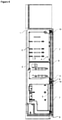
- the mounting member (8) is a member used for mounting the decorative panel (7) onto a built-in household appliance (2) which is placed into the cabinet (1), and comprises a first carrier (9) having a base (11) which is seated onto the base of the cabinet (1), an additional base (12) which extends towards the base (11) and under of the body (3) of the built-in household appliance (2), an extension (13) which extends between the body (3) and the door (4), perpendicular to the base (11) and the additional base (12), and an additional extension (14) which extends downwards from the other end of the base (11) extending out of the cabinet (1), perpendicular to the base (11) and which has one or more than one holder (15) thereon; and a second carrier (10) which is attached to the lower edge of the decorative panel (7), which moves on the additional extension (14) upwards and downwards in the vertical direction and which has additional holders (16) on the side thereof facing the additional extension (14), matching the form of the holders (15) on the additional extension (14) so as to engage with the same ( Figure 1 and Figure
- the first carrier (9) is placed to the lower front section of the cabinet (1) and the built-in household appliance (2).
- the base (11) of the first carrier (9) extends towards the base of the cabinet (1) while the additional base (12) extends towards the base of the body (3) which is at a distance from the bottom of the cabinet (1).
- the extension (13) is positioned between the body (3) and the door (4) of the built-in household appliance (2) while the additional extension (14) extends downwards from the front side of the cabinet (1).
- the second carrier (10) which is attached under the decorative panel (7) is moved closer and attached to the first carrier (9) together with the decorative panel (7) such that the additional holders (16) engage with the holders (15) on the first carrier (9).
- the horizontal and vertical positions of the decorative panel (7) on the door (4) are determined precisely by adjusting the relative positions of the holders (15) and the additional holders (16) with respect to each other.
- the decorative panel (7) is fixed onto the door (4) and the mounting member (8) is removed from the cabinet (1) and the decorative panel (7).
- the first carrier (9) is prevented from sliding and moving forwards and backwards on the base of the cabinet (1) ( Figure 3 and Figure 4 ).
- the mounting member (8) comprises the base (11) and the additional base (12) which are at different heights.
- the mounting member (8) comprises a support member (17) at the corner between the additional base (12) and the base (11), extending from the base (11) towards additional base (12). The flexing and breaking of the additional base (12) due to the distance between the base (11) and the additional base (12) is prevented by means of the support member (17).
- the mounting member (8) comprises a plurality of holders (15) which extend in a plurality of rows perpendicular to the horizontal plane of the additional extension (14).
- the mounting member (8) further comprises a plurality of additional holders (16) with the same form as the holder (15), arranged on the surface of the second carrier (10) which faces the first carrier (9).
- the holders (15) extend outwards from the surface of the additional extension (14) so as to be inclined upwards while the additional holders (16) extend so as to be inclined downwards. Thereby, the holder (15) and the additional holders (16) are prevented from being broken due to weight and sliding in the vertical direction.
- the mounting member (8) comprises one or more than one fixing member (18) which are provided on the door (4), enabling the decorative panel (7) to be attached from the upper section thereof after the decorative panel (7) is attached to the door (4) from the lower section by means of the first and second carriers (9 and 10) attached to each other.
- the fixing member (18) enables the decorative panel (7) to be attached to the door (4) temporarily after the decorative panel (7) is attached to the door (4) from the lower section thereof.
- the fixing member (18) is removed from the door (4) and the decorative panel (7) is fixed onto the door (4) permanently by means of fixing means.
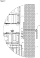
- the temporary attachment of the decorative panel (7) onto the door (4) is performed by means of adhesives ( Figure 5 , Figure 6 and Figure 7 ).
- the second carrier (10) is h-shaped.
- the additional holders (16) are arranged on the back of the second carrier (10).
- the mounting member (8) is used for fixing decorative panels (7) onto the lower and upper doors (5 and 6) of the built-in cooling devices which are placed into cabinets (1) and which have lower and upper doors (5 and 6).
- the required distance between the lower and upper doors (5 and 6) is adjusted by means of the mounting member (8).
- the decorative panels (7) which are fixed onto the lower and upper doors (5 and 6) are enabled to be grouped on the same plane so as to be aligned with each other ( Figure 8 and Figure 9 ).
- the decorative panel (7) is enabled to be attached to the door (4) precisely and easily without the need for taking measurements on the built-in household appliance (2) and the decorative panel (7). Furthermore, as the position of the decorative panel (7) is determined without taking measurements, the need for the service personnel to use measurement devices is eliminated, thus decreasing the time, cost and labor needed to place the built-in household appliance (2) into the cabinet (1).
- the mounting member (8) further decreases the service failure rate by preventing the built-in household appliance (2) from being grouped wrongly in the cabinet (1).
Description
- The present invention relates to a mounting member which is used for the mounting of the decorative panels onto the built-in household appliances.
- It is required that the built-in household appliances are placed into a cabinet and decorative panels which suit the properties of the cabinet have to be mounted onto the same. During the mounting process, the positioning of the decorative panels is critical both aesthetically and functionally. Thus, the mounting process is performed by authorized service personnel by taking precise measurements. As the household appliance is heavy and hard to move inside the cabinet and the material and the size of the cabinet vary, the mounting process is a substantially time consuming and laborious process.
- In the state of the art French Patent Application No.
FR2802787 - Another state of the art embodiment is disclosed in the International Patent Application No.
WO2014177226 . This document discloses an adjustment mechanism which enables the decorative panel to be mounted easily onto the built-in dishwasher. - In another the state of the art embodiment, Turkish Patent Application No.
TR201111997 - Another state of the art embodiment is disclosed in the Patent Application No.
EP0718459 . This document discloses a mechanism which enables the built-in household appliance to be placed into the cabinet properly. - In another the state of the art embodiment, Turkish Patent Application No.
TR201206553 - In the state of the art German Patent Application No.
DE102017130849 , a mounting member is disclosed, which is placed into the cabinet and which enables the decorative panel to be mounted onto the built-in household appliance. - In the state of the art German Patent Application No.
DE19852330 , a household appliance having door and means for attaching a door leaf to the door is disclosed. - The aim of the present invention is the realization of a mounting member which is used for the precise and easy mounting of the decorative panels onto the built-in household appliances.
- The mounting member realized in order to attain the aim of the present invention, explicated in the first claim and the respective claims thereof, is a member used for the mounting of the decorative panel onto a built-in household appliance, and comprises a base which is seated on the base of the cabinet; an additional base which extends towards the base and the body of the built-in household appliance; a first carrier having an extension which extends between the body of the household appliance and the door, perpendicular to the base and the additional base and an additional extension which extends downwards outside the cabinet from the other end of the base, perpendicular to the base and which has holders extending outwards; and a second carrier which is attached to the lower edge of the decorative panel, which moves on the additional extension upwards and downwards in the vertical direction and which has additional holders matching the form of the holders on the additional extension at the side thereof facing the additional extension so as to engage with the holders.
- In the embodiment of the present invention, after the built-in household appliance is placed into the cabinet, the first carrier is placed to the lower front section of the cabinet and the built-in household appliance. In this embodiment, the base of the first carrier extends towards the base of the cabinet and the additional base extends under the body of the built-in household appliance which is at a distance from the base of the cabinet while the extension is positioned between the body and the door of the built-in household appliance and the additional extension extends downwards from the front of the cabinet. By means of the extension and the additional extension which extend perpendicular to the base and the additional base, the first carrier is prevented from sliding and moving forwards and backwards on the base of the cabinet.
- The second carrier which is attached under the decorative panel is attached to the first carrier together with the decorative panel such that the additional holders engage with the holders on the first carrier. The horizontal and vertical positions of the decorative panel on the door are determined precisely by adjusting the relative positions of the holders and the additional holders with respect to each other. The mounting member is removed from the cabinet and the decorative panel after the decorative panel is fixed to the door.
- In an embodiment of the present invention, heights of the base and the additional panel are different from each other. To prevent the breaking of the additional base by flexing due to the distance between the base and the additional base, a support member extending from the base towards the additional base is provided at the corner between the additional base and the base.
- In another embodiment of the present invention, the mounting member comprises a plurality of holders which extend in a plurality of rows perpendicular to the horizontal plane of the additional extension. In this embodiment, mounting member further comprises a plurality of additional holders with the same form as the holder, arranged on the surface of the second carrier which faces the first carrier. By adjusting the height at which the holder and the additional holder engage with each other, the position of the decorative panel on the door is determined. Furthermore, in the embodiment of the present invention, the holders extend outwards from the surface of the additional extension so as to be inclined upwards while the additional extensions extend so as to be inclined downwards. Thereby, the holder and the additional holders are prevented from being broken due to weight and sliding in the vertical direction.
- In another embodiment of the present invention, the mounting member comprises one or more than one fixing member which is provided on the door, enabling the decorative panel to be attached from the upper section thereof after the decorative panel is attached to the door from the lower section by means of the first and second carriers attached to each other. The fixing member enables the decorative panel to be attached to the door temporarily after the decorative panel is attached to the door from the lower section. After the completion of this process, the fixing member is removed from the door and the decorative panel is fixed onto the door permanently by means of fixing means. The temporary attachment of the decorative panel onto the door is performed by means of adhesives.
- In another embodiment of the present invention, the second carrier is h-shaped. In this embodiment, the additional holders are arranged on the back of the second carrier.
- In another embodiment of the present invention, the mounting member is used for fixing decorative panels onto the lower and upper doors of the built-in cooling devices which are placed into cabinets and which have lower and upper doors. In this embodiment, the required distance between the lower and upper doors is adjusted by means of the mounting member. By means of the mounting member, the decorative panels which are fixed onto the lower and upper doors are enabled to be grouped on the same plane so as to be aligned with each other.
- By means of the present invention, the decorative panel is enabled to be attached to the door precisely and easily without the need for taking measurements on the built-in household appliance and the decorative panel. Furthermore, as the position of the decorative panel on the door is determined without taking measurements, the need for the service personnel to use measurement devices is eliminated, thus decreasing the time, cost and labor needed to place the built-in household appliance into the cabinet. The mounting member further decreases the service failure rate by preventing the built-in household appliance from being grouped wrongly in the cabinet.
- The mounting member realized in order to attain the aim of the present invention is illustrated in the attached figures, where:
-
Figure 1 - is the perspective view of a built-in household appliance and the cabinet. -
Figure 2 - is the sideways cross-sectional view of the mounting member. -
Figure 3 - is the perspective view of the first carrier. -
Figure 4 - is the perspective view of the second carrier. -
Figure 5 - is the cross-sectional view of the lower decorative panel during the mounting process. -
Figure 6 - is the view of detail A inFigure 5 . -
Figure 7 - is the view of detail B inFigure 5 . -
Figure 8 - is the cross-sectional view of the upper decorative panel during the mounting process. -
Figure 9 - is the view of the detail C inFigure 8 . - The elements illustrated in the figures are numbered as follows:
- 1. Cabinet
- 2. Built-in household appliance
- 3. Body
- 4. Door
- 5. Lower door
- 6. Upper door
- 7. Decorative panel
- 8. Mounting member
- 9. First carrier
- 10. Second carrier
- 11. Base
- 12. Additional base
- 13. Extension
- 14. Additional extension
- 15. Holder
- 16. Additional holder
- 17. Support member
- 18. Fixing member
- The mounting member (8) is a member used for mounting the decorative panel (7) onto a built-in household appliance (2) which is placed into the cabinet (1), and comprises a first carrier (9) having a base (11) which is seated onto the base of the cabinet (1), an additional base (12) which extends towards the base (11) and under of the body (3) of the built-in household appliance (2), an extension (13) which extends between the body (3) and the door (4), perpendicular to the base (11) and the additional base (12), and an additional extension (14) which extends downwards from the other end of the base (11) extending out of the cabinet (1), perpendicular to the base (11) and which has one or more than one holder (15) thereon; and a second carrier (10) which is attached to the lower edge of the decorative panel (7), which moves on the additional extension (14) upwards and downwards in the vertical direction and which has additional holders (16) on the side thereof facing the additional extension (14), matching the form of the holders (15) on the additional extension (14) so as to engage with the same (
Figure 1 andFigure 2 ). - In the embodiment of the present invention, after the built-in household appliance (2) is placed into the cabinet (1), the first carrier (9) is placed to the lower front section of the cabinet (1) and the built-in household appliance (2). During this process, the base (11) of the first carrier (9) extends towards the base of the cabinet (1) while the additional base (12) extends towards the base of the body (3) which is at a distance from the bottom of the cabinet (1). In this case, the extension (13) is positioned between the body (3) and the door (4) of the built-in household appliance (2) while the additional extension (14) extends downwards from the front side of the cabinet (1). At the same time, the second carrier (10) which is attached under the decorative panel (7) is moved closer and attached to the first carrier (9) together with the decorative panel (7) such that the additional holders (16) engage with the holders (15) on the first carrier (9). The horizontal and vertical positions of the decorative panel (7) on the door (4) are determined precisely by adjusting the relative positions of the holders (15) and the additional holders (16) with respect to each other. After this step, the decorative panel (7) is fixed onto the door (4) and the mounting member (8) is removed from the cabinet (1) and the decorative panel (7). Moreover, by means of the extension (13) and the additional extension (14) which extend perpendicular to the base (11) and the additional base (12), the first carrier (9) is prevented from sliding and moving forwards and backwards on the base of the cabinet (1) (
Figure 3 and Figure 4 ). - In an embodiment of the present invention, the mounting member (8) comprises the base (11) and the additional base (12) which are at different heights. In this embodiment, the mounting member (8) comprises a support member (17) at the corner between the additional base (12) and the base (11), extending from the base (11) towards additional base (12). The flexing and breaking of the additional base (12) due to the distance between the base (11) and the additional base (12) is prevented by means of the support member (17).
- In another embodiment of the present invention, the mounting member (8) comprises a plurality of holders (15) which extend in a plurality of rows perpendicular to the horizontal plane of the additional extension (14). In this embodiment, the mounting member (8) further comprises a plurality of additional holders (16) with the same form as the holder (15), arranged on
the surface of the second carrier (10) which faces the first carrier (9). By adjusting the height at which the holder (15) and the additional holder (16) engage with each other, the position of the decorative panel (7) on the door (4) is determined. Furthermore, in the embodiment of the present invention, the holders (15) extend outwards from the surface of the additional extension (14) so as to be inclined upwards while the additional holders (16) extend so as to be inclined downwards. Thereby, the holder (15) and the additional holders (16) are prevented from being broken due to weight and sliding in the vertical direction. - In another embodiment of the present invention, the mounting member (8) comprises one or more than one fixing member (18) which are provided on the door (4), enabling the decorative panel (7) to be attached from the upper section thereof after the decorative panel (7) is attached to the door (4) from the lower section by means of the first and second carriers (9 and 10) attached to each other. The fixing member (18) enables the decorative panel (7) to be attached to the door (4) temporarily after the decorative panel (7) is attached to the door (4) from the lower section thereof. After the completion of this process, the fixing member (18) is removed from the door (4) and the decorative panel (7) is fixed onto the door (4) permanently by means of fixing means. The temporary attachment of the decorative panel (7) onto the door (4) is performed by means of adhesives (
Figure 5 ,Figure 6 and Figure 7 ). - In another embodiment of the present invention, the second carrier (10) is h-shaped. In this embodiment, the additional holders (16) are arranged on the back of the second carrier (10).
- In another embodiment of the present invention, the mounting member (8) is used for fixing decorative panels (7) onto the lower and upper doors (5 and 6) of the built-in cooling devices which are placed into cabinets (1) and which have lower and upper doors (5 and 6). In this embodiment, the required distance between the lower and upper doors (5 and 6) is adjusted by means of the mounting member (8). By means of the mounting member (8), the decorative panels (7) which are fixed onto the lower and upper doors (5 and 6) are enabled to be grouped on the same plane so as to be aligned with each other (
Figure 8 andFigure 9 ). - By means of the present invention, the decorative panel (7) is enabled to be attached to the door (4) precisely and easily without the need for taking measurements on the built-in household appliance (2) and the decorative panel (7). Furthermore, as the position of the decorative panel (7) is determined without taking measurements, the need for the service personnel to use measurement devices is eliminated, thus decreasing the time, cost and labor needed to place the built-in household appliance (2) into the cabinet (1). The mounting member (8) further decreases the service failure rate by preventing the built-in household appliance (2) from being grouped wrongly in the cabinet (1).
Claims (11)
- A mounting member (8) for mounting a decorative panel (7) onto a built-in household appliance (2) having a body (3) and a door (4), the household appliance being placed into a cabinet (1), the mounting member (8) comprising a first carrier (9) having a base (11) which is seated onto the base of the cabinet (1), an additional base (12) which extends towards the base (11) and under the body (3) of the built-in household appliance (2), and an additional extension (14) which extends downwards from an other end of the base (11) extending out of the cabinet (1), perpendicular to the base (11) and which has holders (15) thereon; and a second carrier (10) which is attached to the lower edge of the decorative panel (7), which moves on the additional extension (14) upwards and downwards in the vertical direction and which has additional holders (16) on the side thereof facing the additional extension (14), matching the form of the holders (15) on the additional extension (14) so as to engage with the same, the mounting member (8) being characterized by further comprising an extension (13) which extends between the body (3) and the door (4), perpendicular to the base (11) and the additional base (12).
- A mounting member (8) as in Claim 1, characterized by the base (11) and the additional base (12) which are at different heights.
- A mounting member (8) as in Claim 2, characterized by a support member (17) at the corner between the additional base (12) and the base (11), extending from the base (11) towards additional base (12).
- A mounting member (8) as in Claim 1, characterized by a plurality of holders (15) which extend in a plurality of rows perpendicular to the horizontal plane of the additional extension (14).
- A mounting member (8) as in Claim 4, characterized by a plurality of additional holders (16) with the same form as the holder (5), arranged on the surface of the second carrier (10) which faces the first carrier (9).
- A mounting member (8) as in Claim 4, characterized by the holders (15) which extend outwards from the surface of the additional extension (14) so as to be inclined upwards.
- A mounting member (8) as in Claim 5 and Claim 6, characterized by the additional holders (16) which extend so as to be inclined downwards.
- A mounting member (8) as in Claim 1, characterized by one or more than one fixing member (18) which are provided on the door (4), enabling the decorative panel (7) to be attached from the upper section thereof
- A mounting member (8) as in Claim 1, characterized by the second carrier (10) which is h-shaped.
- A mounting member (8) as in Claims 1 and 5 and 7 and 9, characterized by the additional holders (16) which are arranged on the back of the second carrier (10).
- A mounting member (8) as in any one of the above claims, suitable for fixing decorative panels (7) onto lower and upper doors (5 and 6) of built-in cooling devices which are placed into cabinets (1) and which have lower and upper doors (5 and 6).
Priority Applications (1)
| Application Number | Priority Date | Filing Date | Title |
|---|---|---|---|
| PL20193611T PL3789706T3 (en) | 2019-09-05 | 2020-08-31 | A mounting member for the mounting of the decorative panel to the built-in household appliance |
Applications Claiming Priority (1)
| Application Number | Priority Date | Filing Date | Title |
|---|---|---|---|
| TR201913434 | 2019-09-05 |
Publications (2)
| Publication Number | Publication Date |
|---|---|
| EP3789706A1 EP3789706A1 (en) | 2021-03-10 |
| EP3789706B1 true EP3789706B1 (en) | 2022-03-09 |
Family
ID=72292360
Family Applications (1)
| Application Number | Title | Priority Date | Filing Date |
|---|---|---|---|
| EP20193611.9A Active EP3789706B1 (en) | 2019-09-05 | 2020-08-31 | A mounting member for the mounting of the decorative panel to the built-in household appliance |
Country Status (2)
| Country | Link |
|---|---|
| EP (1) | EP3789706B1 (en) |
| PL (1) | PL3789706T3 (en) |
Family Cites Families (8)
| Publication number | Priority date | Publication date | Assignee | Title |
|---|---|---|---|---|
| EP0718459B1 (en) | 1994-10-25 | 2003-04-02 | Whirlpool Europe B.V. | Method and device for attaching a door leaf to appliance door of a built-in domestic appliance |
| DE4443852C1 (en) * | 1994-10-25 | 1995-12-07 | Bauknecht Hausgeraete | Mounting door plate on fitted appliance |
| DE19644734C1 (en) * | 1996-10-28 | 1998-05-07 | Bauknecht Hausgeraete | Method for fitting door panel to door of domestic apparatus |
| DE19712418C1 (en) * | 1997-03-25 | 1998-04-30 | Whirlpool Co | Attachment of additional door leaf to appliance door |
| DE19852330C2 (en) * | 1998-11-13 | 2000-10-05 | Aeg Hausgeraete Gmbh | Household appliance with an appliance door and means for attaching a door leaf to the appliance door and method for attaching a door leaf to the appliance door of a household appliance |
| FR2802787B3 (en) | 1999-12-22 | 2001-10-26 | Merlomi Elettrodomestici Spa S | BUILT-IN HOUSEHOLD APPLIANCE, ESPECIALLY A REFRIGERATOR EQUIPPED WITH DEVICES FOR MILLIMETER ADJUSTMENT OF THE POSITION OF THE FRONTAL FINISH TRIM |
| EP2991535A1 (en) | 2013-05-03 | 2016-03-09 | Arçelik Anonim Sirketi | Mounting assembly for securing a decorative panel onto built-in household appliance and mounting method |
| SI25343A (en) | 2017-01-16 | 2018-07-31 | Gorenje Gospodinjski Aparati D.D. | Insert household appliance with decorative panel |
-
2020
- 2020-08-31 EP EP20193611.9A patent/EP3789706B1/en active Active
- 2020-08-31 PL PL20193611T patent/PL3789706T3/en unknown
Also Published As
| Publication number | Publication date |
|---|---|
| PL3789706T3 (en) | 2022-06-27 |
| EP3789706A1 (en) | 2021-03-10 |
Similar Documents
| Publication | Publication Date | Title |
|---|---|---|
| EP1929928B1 (en) | Dishwasher rack | |
| US8840205B2 (en) | Refrigerator appliance and a shelf assembly for the same | |
| WO2013045543A1 (en) | A rack suitable for usage in a dishwasher and the dishwasher wherein the rack is used | |
| US9650789B2 (en) | Attachment brackets for panel mounting | |
| EP2854599B1 (en) | A built-in household appliance comprising a decorative panel | |
| US10397984B2 (en) | Range with suspended cooktop | |
| CN110621838B (en) | Furniture and method for producing furniture | |
| EP3789706B1 (en) | A mounting member for the mounting of the decorative panel to the built-in household appliance | |
| CN106137085A (en) | A kind of use in dishwasher scalable shelf | |
| EP3167755B1 (en) | Drawer slide assembly | |
| EP1145667B1 (en) | Method for fastening a cupboard door to the door of a built-in refrigerator | |
| EP3141850B1 (en) | A shelf system | |
| EP1960217B1 (en) | A household appliance | |
| EP3397129B1 (en) | A dishwasher | |
| US20120146474A1 (en) | Positioning base with adjustable support levelers for a household appliance | |
| US7971944B2 (en) | Mounting for an extension piece of a tall cabinet | |
| CN107435956B (en) | Hearth assembly, cooker for hearth assembly and edge covering | |
| EP3585215B1 (en) | Refrigerated sales cabinet | |
| CN110260369A (en) | Gap adjustment tooling, assemble method and microwave furnace panel are installed | |
| EP3795909A1 (en) | A cooking device | |
| WO2019129402A1 (en) | An oven comprising shelf support made of wire | |
| CN210688376U (en) | Range hood on-hook subassembly | |
| CN113163945A (en) | Drawer and furniture | |
| EP2580991B1 (en) | Perfected positioning and supporting group for the wall assembly of a piece of furniture and method of use thereof | |
| GB2105983A (en) | Control panel |
Legal Events
| Date | Code | Title | Description |
|---|---|---|---|
| PUAI | Public reference made under article 153(3) epc to a published international application that has entered the european phase |
Free format text: ORIGINAL CODE: 0009012 |
|
| STAA | Information on the status of an ep patent application or granted ep patent |
Free format text: STATUS: REQUEST FOR EXAMINATION WAS MADE |
|
| 17P | Request for examination filed |
Effective date: 20200831 |
|
| AK | Designated contracting states |
Kind code of ref document: A1 Designated state(s): AL AT BE BG CH CY CZ DE DK EE ES FI FR GB GR HR HU IE IS IT LI LT LU LV MC MK MT NL NO PL PT RO RS SE SI SK SM TR |
|
| AX | Request for extension of the european patent |
Extension state: BA ME |
|
| GRAP | Despatch of communication of intention to grant a patent |
Free format text: ORIGINAL CODE: EPIDOSNIGR1 |
|
| STAA | Information on the status of an ep patent application or granted ep patent |
Free format text: STATUS: GRANT OF PATENT IS INTENDED |
|
| INTG | Intention to grant announced |
Effective date: 20211222 |
|
| GRAS | Grant fee paid |
Free format text: ORIGINAL CODE: EPIDOSNIGR3 |
|
| GRAA | (expected) grant |
Free format text: ORIGINAL CODE: 0009210 |
|
| STAA | Information on the status of an ep patent application or granted ep patent |
Free format text: STATUS: THE PATENT HAS BEEN GRANTED |
|
| AK | Designated contracting states |
Kind code of ref document: B1 Designated state(s): AL AT BE BG CH CY CZ DE DK EE ES FI FR GB GR HR HU IE IS IT LI LT LU LV MC MK MT NL NO PL PT RO RS SE SI SK SM TR |
|
| REG | Reference to a national code |
Ref country code: CH Ref legal event code: EP Ref country code: AT Ref legal event code: REF Ref document number: 1474498 Country of ref document: AT Kind code of ref document: T Effective date: 20220315 |
|
| REG | Reference to a national code |
Ref country code: IE Ref legal event code: FG4D |
|
| REG | Reference to a national code |
Ref country code: DE Ref legal event code: R096 Ref document number: 602020002152 Country of ref document: DE |
|
| REG | Reference to a national code |
Ref country code: LT Ref legal event code: MG9D |
|
| REG | Reference to a national code |
Ref country code: NL Ref legal event code: MP Effective date: 20220309 |
|
| PG25 | Lapsed in a contracting state [announced via postgrant information from national office to epo] |
Ref country code: SE Free format text: LAPSE BECAUSE OF FAILURE TO SUBMIT A TRANSLATION OF THE DESCRIPTION OR TO PAY THE FEE WITHIN THE PRESCRIBED TIME-LIMIT Effective date: 20220309 Ref country code: RS Free format text: LAPSE BECAUSE OF FAILURE TO SUBMIT A TRANSLATION OF THE DESCRIPTION OR TO PAY THE FEE WITHIN THE PRESCRIBED TIME-LIMIT Effective date: 20220309 Ref country code: NO Free format text: LAPSE BECAUSE OF FAILURE TO SUBMIT A TRANSLATION OF THE DESCRIPTION OR TO PAY THE FEE WITHIN THE PRESCRIBED TIME-LIMIT Effective date: 20220609 Ref country code: LT Free format text: LAPSE BECAUSE OF FAILURE TO SUBMIT A TRANSLATION OF THE DESCRIPTION OR TO PAY THE FEE WITHIN THE PRESCRIBED TIME-LIMIT Effective date: 20220309 Ref country code: HR Free format text: LAPSE BECAUSE OF FAILURE TO SUBMIT A TRANSLATION OF THE DESCRIPTION OR TO PAY THE FEE WITHIN THE PRESCRIBED TIME-LIMIT Effective date: 20220309 Ref country code: BG Free format text: LAPSE BECAUSE OF FAILURE TO SUBMIT A TRANSLATION OF THE DESCRIPTION OR TO PAY THE FEE WITHIN THE PRESCRIBED TIME-LIMIT Effective date: 20220609 |
|
| REG | Reference to a national code |
Ref country code: AT Ref legal event code: MK05 Ref document number: 1474498 Country of ref document: AT Kind code of ref document: T Effective date: 20220309 |
|
| PG25 | Lapsed in a contracting state [announced via postgrant information from national office to epo] |
Ref country code: LV Free format text: LAPSE BECAUSE OF FAILURE TO SUBMIT A TRANSLATION OF THE DESCRIPTION OR TO PAY THE FEE WITHIN THE PRESCRIBED TIME-LIMIT Effective date: 20220309 Ref country code: GR Free format text: LAPSE BECAUSE OF FAILURE TO SUBMIT A TRANSLATION OF THE DESCRIPTION OR TO PAY THE FEE WITHIN THE PRESCRIBED TIME-LIMIT Effective date: 20220610 Ref country code: FI Free format text: LAPSE BECAUSE OF FAILURE TO SUBMIT A TRANSLATION OF THE DESCRIPTION OR TO PAY THE FEE WITHIN THE PRESCRIBED TIME-LIMIT Effective date: 20220309 |
|
| PG25 | Lapsed in a contracting state [announced via postgrant information from national office to epo] |
Ref country code: NL Free format text: LAPSE BECAUSE OF FAILURE TO SUBMIT A TRANSLATION OF THE DESCRIPTION OR TO PAY THE FEE WITHIN THE PRESCRIBED TIME-LIMIT Effective date: 20220309 |
|
| PG25 | Lapsed in a contracting state [announced via postgrant information from national office to epo] |
Ref country code: SM Free format text: LAPSE BECAUSE OF FAILURE TO SUBMIT A TRANSLATION OF THE DESCRIPTION OR TO PAY THE FEE WITHIN THE PRESCRIBED TIME-LIMIT Effective date: 20220309 Ref country code: SK Free format text: LAPSE BECAUSE OF FAILURE TO SUBMIT A TRANSLATION OF THE DESCRIPTION OR TO PAY THE FEE WITHIN THE PRESCRIBED TIME-LIMIT Effective date: 20220309 Ref country code: RO Free format text: LAPSE BECAUSE OF FAILURE TO SUBMIT A TRANSLATION OF THE DESCRIPTION OR TO PAY THE FEE WITHIN THE PRESCRIBED TIME-LIMIT Effective date: 20220309 Ref country code: PT Free format text: LAPSE BECAUSE OF FAILURE TO SUBMIT A TRANSLATION OF THE DESCRIPTION OR TO PAY THE FEE WITHIN THE PRESCRIBED TIME-LIMIT Effective date: 20220711 Ref country code: ES Free format text: LAPSE BECAUSE OF FAILURE TO SUBMIT A TRANSLATION OF THE DESCRIPTION OR TO PAY THE FEE WITHIN THE PRESCRIBED TIME-LIMIT Effective date: 20220309 Ref country code: EE Free format text: LAPSE BECAUSE OF FAILURE TO SUBMIT A TRANSLATION OF THE DESCRIPTION OR TO PAY THE FEE WITHIN THE PRESCRIBED TIME-LIMIT Effective date: 20220309 Ref country code: CZ Free format text: LAPSE BECAUSE OF FAILURE TO SUBMIT A TRANSLATION OF THE DESCRIPTION OR TO PAY THE FEE WITHIN THE PRESCRIBED TIME-LIMIT Effective date: 20220309 Ref country code: AT Free format text: LAPSE BECAUSE OF FAILURE TO SUBMIT A TRANSLATION OF THE DESCRIPTION OR TO PAY THE FEE WITHIN THE PRESCRIBED TIME-LIMIT Effective date: 20220309 |
|
| PG25 | Lapsed in a contracting state [announced via postgrant information from national office to epo] |
Ref country code: IS Free format text: LAPSE BECAUSE OF FAILURE TO SUBMIT A TRANSLATION OF THE DESCRIPTION OR TO PAY THE FEE WITHIN THE PRESCRIBED TIME-LIMIT Effective date: 20220709 Ref country code: AL Free format text: LAPSE BECAUSE OF FAILURE TO SUBMIT A TRANSLATION OF THE DESCRIPTION OR TO PAY THE FEE WITHIN THE PRESCRIBED TIME-LIMIT Effective date: 20220309 |
|
| REG | Reference to a national code |
Ref country code: DE Ref legal event code: R097 Ref document number: 602020002152 Country of ref document: DE |
|
| PLBE | No opposition filed within time limit |
Free format text: ORIGINAL CODE: 0009261 |
|
| STAA | Information on the status of an ep patent application or granted ep patent |
Free format text: STATUS: NO OPPOSITION FILED WITHIN TIME LIMIT |
|
| PG25 | Lapsed in a contracting state [announced via postgrant information from national office to epo] |
Ref country code: DK Free format text: LAPSE BECAUSE OF FAILURE TO SUBMIT A TRANSLATION OF THE DESCRIPTION OR TO PAY THE FEE WITHIN THE PRESCRIBED TIME-LIMIT Effective date: 20220309 |
|
| 26N | No opposition filed |
Effective date: 20221212 |
|
| PG25 | Lapsed in a contracting state [announced via postgrant information from national office to epo] |
Ref country code: SI Free format text: LAPSE BECAUSE OF FAILURE TO SUBMIT A TRANSLATION OF THE DESCRIPTION OR TO PAY THE FEE WITHIN THE PRESCRIBED TIME-LIMIT Effective date: 20220309 |
|
| PG25 | Lapsed in a contracting state [announced via postgrant information from national office to epo] |
Ref country code: MC Free format text: LAPSE BECAUSE OF FAILURE TO SUBMIT A TRANSLATION OF THE DESCRIPTION OR TO PAY THE FEE WITHIN THE PRESCRIBED TIME-LIMIT Effective date: 20220309 |
|
| PG25 | Lapsed in a contracting state [announced via postgrant information from national office to epo] |
Ref country code: LU Free format text: LAPSE BECAUSE OF NON-PAYMENT OF DUE FEES Effective date: 20220831 |
|
| REG | Reference to a national code |
Ref country code: BE Ref legal event code: MM Effective date: 20220831 |
|
| PG25 | Lapsed in a contracting state [announced via postgrant information from national office to epo] |
Ref country code: IT Free format text: LAPSE BECAUSE OF FAILURE TO SUBMIT A TRANSLATION OF THE DESCRIPTION OR TO PAY THE FEE WITHIN THE PRESCRIBED TIME-LIMIT Effective date: 20220309 Ref country code: IE Free format text: LAPSE BECAUSE OF NON-PAYMENT OF DUE FEES Effective date: 20220831 Ref country code: FR Free format text: LAPSE BECAUSE OF NON-PAYMENT OF DUE FEES Effective date: 20220831 |
|
| PG25 | Lapsed in a contracting state [announced via postgrant information from national office to epo] |
Ref country code: BE Free format text: LAPSE BECAUSE OF NON-PAYMENT OF DUE FEES Effective date: 20220831 |
|
| PGFP | Annual fee paid to national office [announced via postgrant information from national office to epo] |
Ref country code: TR Payment date: 20230731 Year of fee payment: 4 |
|
| PGFP | Annual fee paid to national office [announced via postgrant information from national office to epo] |
Ref country code: PL Payment date: 20230818 Year of fee payment: 4 Ref country code: DE Payment date: 20230821 Year of fee payment: 4 |
|
| REG | Reference to a national code |
Ref country code: CH Ref legal event code: PL |