WO2014177226A1 - Mounting assembly for securing a decorative panel onto built-in household appliance and mounting method - Google Patents
Mounting assembly for securing a decorative panel onto built-in household appliance and mounting method Download PDFInfo
- Publication number
- WO2014177226A1 WO2014177226A1 PCT/EP2013/059270 EP2013059270W WO2014177226A1 WO 2014177226 A1 WO2014177226 A1 WO 2014177226A1 EP 2013059270 W EP2013059270 W EP 2013059270W WO 2014177226 A1 WO2014177226 A1 WO 2014177226A1
- Authority
- WO
- WIPO (PCT)
- Prior art keywords
- decorative panel
- mounting assembly
- front door
- coupling member
- alignment portion
- Prior art date
Links
Images


Classifications
-
- A—HUMAN NECESSITIES
- A47—FURNITURE; DOMESTIC ARTICLES OR APPLIANCES; COFFEE MILLS; SPICE MILLS; SUCTION CLEANERS IN GENERAL
- A47L—DOMESTIC WASHING OR CLEANING; SUCTION CLEANERS IN GENERAL
- A47L15/00—Washing or rinsing machines for crockery or tableware
- A47L15/42—Details
- A47L15/4251—Details of the casing
- A47L15/4257—Details of the loading door
- A47L15/4265—Arrangements of door covering/decoration panels or plinths, e.g. for integrated dishwashers
-
- A—HUMAN NECESSITIES
- A47—FURNITURE; DOMESTIC ARTICLES OR APPLIANCES; COFFEE MILLS; SPICE MILLS; SUCTION CLEANERS IN GENERAL
- A47B—TABLES; DESKS; OFFICE FURNITURE; CABINETS; DRAWERS; GENERAL DETAILS OF FURNITURE
- A47B96/00—Details of cabinets, racks or shelf units not covered by a single one of groups A47B43/00 - A47B95/00; General details of furniture
- A47B96/20—Furniture panels or like furniture elements
- A47B2096/208—Decorative panels for household appliances
Definitions
- the present invention relates to a fully-integrated and a semi-integrated built-in household appliance, in particular a dishwasher, and specifically to a mounting assembly for securing a decorative panel on a front door of a built-in household appliance and a mounting method using the same.
- a built-in household appliance is usually concealed with a decorative panel matching a design of the kitchen furniture and the dimensions of the household appliance.
- Household appliances, in particular dishwashers may have their control panels either on a front surface or on an upper edge of the front door. Consequently, depending on an arrangement of the control panel, the dishwasher may be either fully integrated or semi-integrated with the kitchen furniture as the customer must have access to the control panel.
- a customer generally purchases a built-in dishwasher and a matching decorative panel in an unassembled state. After delivery of the goods, the decorative panel must be fixed onto the front door at its place of installation by using a mounting assembly provided by the manufacturer.
- EP 0 632 156 A1 discloses a conventionally used system for fixing a front panel to a door of a household appliance, in particular a dish washing machine for domestic use.
- the system disclosed therein comprises a pair of cooperating coupling means for interconnecting a rear surface of the front panel and an outer surface of the door.
- the aforementioned drawbacks of the known mounting assemblies are not exhaustive.
- the appliance door of a built-in dishwasher is generally constructed with several openings for receiving corresponding parts of the mounting assembly. Therefore, a noise level produced by the dishwasher during operation may be relatively high, if no additional measures are taken to prevent sound from leaking through these openings into the kitchen environment.
- An objective of the present invention is to provide a mounting assembly for securing a decorative panel onto a front door of a built-in household appliance such as a dishwasher, and a method of mounting a decorative panel using the same which enables accurate and easy mounting of decorative panels, and overcomes the drawbacks of the aforementioned prior art.
- the mounting assembly comprises a coupling member for interconnecting a rear surface of the decorative panel and an outer surface of the front door.
- the coupling member further comprises an alignment portion integrally formed with the coupling member, for aligning and positioning the coupling member, relative the edges of the decorative panel, at a designated location on the rear surface of the decorative panel.
- the alignment portion has been provided with alignment markings for facilitating alignment and positioning of the mounting assembly.
- Household appliances may come in different dimensions and designs. Therefore, a decorative panel must have a size which specifically matches the dimensions and the design of the household appliance. Consequently, the designated location for installing the mounting assembly on the decorative panel may relatively shift with respect to the edges of the decorative panel depending on the specific dimensions and design of the appliance as well. Therefore, in another preferred embodiment, the alignment portion has been provided with a plurality of breaking grooves. The alignment portion can be shortened to a designated length matching the decorative panel by truncating the alignment portion at a respective breaking groove prescribed by the manufacturer.
- the mounting assembly has a flat structure so that the mounting assembly can be sandwiched between a rear surface of the decorative panel and an outer surface of the front door.
- the mounting assembly of the present invention interconnects the decorative panel and the front door almost in a gapless fashion.
- the mounting assembly has been provided with a fixing means for fixing the coupling member flush on the rear surface of the decorative panel.
- the mounting assembly has been provided with a plurality of projections extending from a surface of the coupling member facing the front door, which are respectively insertable into a plurality of corresponding holes formed in the front door. The projections exactly fit into the holes. Thereby, the decorative panel can be secured on the front door while also acoustically sealing the holes.
- the mounting assembly is provided together with a plurality of double sided adhesive tapes which can be arranged between the rear surface of the decorative panel and the outer surface of the front door to stick them together.
- the mounting assembly is initially aligned and positioned at a designated location on the decorative panel with reference to the edges of the decorative panel. Thereby, the projections on the mounting assembly exactly meet the holes on the appliance door. If necessary, the mounting assembly is shortened to a designated length as prescribed by the manufacturer matching the dimensions and the design of the household appliance.
- one or more double sided adhesive tapes may be placed between the front door and the decorative panel. Subsequently, the front door can be securely pivoted to a horizontal position for screwing the decorative panel from an inner side of the appliance door to tightly fasten the decorative panel against an outer surface of the appliance door. Therewith, the mounting of the decorative panel is finalized.
- Figure 1 - is a perspective view of a mounting assembly and a perspective view of D detail in the same figure according to a preferred embodiment of the present invention.
- Figure 2 - is a view of the rear surface of a decorative panel to be mounted on a front door of a household appliance according to the present invention.
- Figure 3 - is a top view of the mounting assembly shown in Figure 1 installed at a designated location on the decorative panel shown in Figure 2.
- Figure 4 - is a side view of the mounting assembly shown in Figure 1 in a truncated state.
- Figure 5 - is a top view of the mounting assembly shown in Figure 1 in a truncated state and installed at a designated location on a decorative panel.
- Figure 6 - is an exploded perspective view of the mounting assembly shown in Figure 1 together with screws, prior to fixing of the mounting assembly onto the decorative panel.
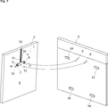
- Figure 7 - is an exploded perspective view of the decorative panel in Figure 3 with the mounting assembly being fixed thereon, prior to securing the decorative panel onto the appliance door having a plurality of double sided adhesives adhered thereon.
- Figure 8 - is a perspective view of the household appliance, prior to anchoring a plurality of screws to tightly fasten the decorative panel against the front door according to the present invention.
- FIG. 7 shows a mounting assembly (1) for securing a decorative panel (2) onto a front door (3) of a built-in household appliance (4) such as a dishwasher.
- the mounting assembly (1) comprises a coupling member (5) for interconnecting a rear surface (6) of the decorative panel (2) and an outer surface of the front door (3).
- Figure 1 shows the mounting assembly (1) of the present invention in more detail.
- the mounting assembly (1) of the present invention further comprises an alignment portion (10) which is integrally formed with the coupling member (5).
- the alignment portion (10) is suitable for aligning and positioning the coupling member (5), relative to the edges of the decorative panel (2), at a designated location on the rear surface (6) of the decorative panel (2) as shown, for example, in Figures 3 and 5.
- Figure 2 shows the rear surface (6) of the decorative panel (2) prior to installing the mounting assembly (1).
- a vertical dashed line has been drawn on the rear surface (6) of the decorative panel (2).
- the dashed line runs parallel to the sides of the decorative panel (2), and divides the decorative panel (2) into two symmetrical parts.
- Figure 3 shows a designated location for installing the mounting assembly (1) on the rear surface (6) of the decorative panel (2).
- the mounting assembly (1) is aligned and positioned on the rear surface (6) such that a tip end of the mounting assembly (1) is positioned at an upper edge of the decorative panel (2), and the dashed line bisects the alignment portion (10).
- the alignment portion (10) has been provided with a couple of alignment markings (12) for providing visual aid when aligning and positioning the coupling member (5) at the designated location on the rear surface (6) of the decorative panel (2).
- the alignment markings (12) are indeed optional. These are intended for facilitating the installation of the mounting assembly (1).
- the alignment portion (10) has been further provided with two through holes formed at a position between the two alignment markings (12) for making the dashed line more visible to the person installing the mounting assembly.
- the alignment markings (12) are provided at opposite ends of the alignment portion (10) in form of V-shaped recesses.
- the V-shaped recesses enable precise alignment with respect to the dashed line.
- V-shaped projections may be used.
- the mounting assembly (1) of the present invention comprises a plurality of breaking grooves (11) which are formed in the alignment portion (10).
- the breaking grooves are suitable for shortening the alignment portion (10) to a designated length prescribed by the manufacturer in relation with the decorative panel (2) to be mounted on the household appliance (4) of interest.
- the breaking grooves (11) are indeed optional.
- the breaking grooves (11) are sequentially located along the alignment portion (10) at predetermined positions.
- the breaking grooves (11) are preferably provided in form of V-shaped grooves, and are preferably separated by a predetermined pitch. The pitch may be predetermined with respect to the decorative panels (2) available by the manufacturer.
- Figure 4 shows the mounting assembly (1) in a truncated state.
- Figure 5 shows a designated location for installing a truncated mounting assembly (1) on the rear surface (6) of the decorative panel (2). As shown in Figure 5, when installing the truncated mounting assembly (1), a tip end of the mounting assembly (1) is positioned at an upper edge of the decorative panel (2), and the mounting assembly (1) is aligned such that the dashed line bisects the alignment portion (10).
- the coupling member (5) and the alignment portion (10) are preferably configured as a flat structure.
- the mounting assembly (1) of the present invention can be sandwiched between a rear surface (6) of the decorative panel (2) and an outer surface of the front door (3) as shown in Figure 7.
- the alignment portion (10) is configured as an elongated flat structure extending from a side of the coupling member (5). It is preferable that the alignment portion (10) and the coupling member (5) configure a T-shaped structure as shown in Figures 3 and 5. The T-shaped structure facilitates installation of the mounting assembly.
- the coupling member (5) has one or more fixing means (7) for fixing the coupling member (5) flush with the rear surface (6) of the decorative panel (2).
- the coupling member (5) has a plurality of projections (8) extending from a surface of the coupling member (5) facing the front door (3), respectively insertable into a plurality of corresponding holes (9) formed in the front door (3).
- the fixing means (7) may be configured by a plurality of openings formed into the coupling member (5) for anchoring screws (13) to tightly fasten the coupling member (5) to the rear side of the decorative panel (2). It is preferred to provide the fixing means (7) as close as possible to the projections (8) to attain a firm coupling between the decorative panel (2) and the front door (3).
- each of the projections (11) may have a hollow portion, such that the fixing means (7) may be respectively formed inside the hollow portions.
- the projections (11) may have a cylindrical shape so as to be plugged into the corresponding holes on the front door to acoustically seal the interior of the appliance.
- the mounting assembly (1) is provided with a plurality of double sided adhesive tapes (14) for arranging between the rear surface (6) of the decorative panel (2) and the outer surface of the front door (3) to stick them together.
- the decorative panel (2) is additionally secured on the front door until it is firmly fixed by the screws as shown in Figure 8.
- the mounting assembly and the double sided adhesive tapes (14) constitute a mounting assembly kit.
- the double sided adhesive tapes (14) are indeed optional.
- a method of mounting a decorative panel (2) onto a front door (3) of a fully integrated or a semi-integrated built-in household appliance (4), in particular a dishwasher, by using the mounting assembly comprising the steps of:
- the length of the alignment portion (10) need not be shortened as shown in Figure 3. However, if the built-in household appliance (4) is a semi-integrating household appliance then a length of the alignment portion (10) ought to be shortened to a designated length as shown, for example, in Figure 5. Then, the coupling member (5) is positioned as shown in Figure 3 or as the case may be as shown in Figure 5 at a respective designated location on the rear surface (6) of the decorative panel (2) by using the alignment portion (10), and preferably the alignment markings such that a tip end of the mounting assembly (1) is positioned at the upper edge of the decorative panel (2) and the mounting assembly (1) bisects the decorative panel (2).
- the coupling member (5) is fixed flush onto the rear surface (6) of the decorative panel (2), preferably by using screws as shown in Figure 6.
- one or more double sided adhesive tapes (14) are preferably adhered on the front door (3) as shown in the right hand side of Figure 7.
- the decorative panel (2) is secured to the front door (3) by inserting the plurality of projections (8) respectively into the plurality of corresponding holes (9) formed in the front door (3) as shown in Figure 7. Thereby, the decorative panel (2) and the front door (3) firmly stick together.
- the front door (3) is manually pivoted to a horizontal position and the decorative panel (2) is subsequently screwed from an inner side of the front door (3) to tightly fasten decorative panel (2) against an outer surface of the front door (3) as shown in Figure 8.
Landscapes
- Washing And Drying Of Tableware (AREA)
Abstract
The present invention provides a mounting assembly (1) for securing a decorative panel (2) onto a front door (3) of a fully integrated or a semi-integrated built-in household appliance (4) such as a dishwasher. The mounting assembly (1) comprises a coupling member (5) for interconnecting a rear surface (6) of the decorative panel (2) and an outer surface of the front door (3); and an alignment portion (10) integrally formed with the coupling member (5), for aligning and positioning the coupling member (5), relative to the edges of the decorative panel (2), at a designated location on the rear surface (6) of the decorative panel (2).
Description
The present invention relates to a fully-integrated and a semi-integrated built-in household appliance, in particular a dishwasher, and specifically to a mounting assembly for securing a decorative panel on a front door of a built-in household appliance and a mounting method using the same.
It is customary to install a household appliance underneath a kitchen counter, between cabinets, and to integrate it with the kitchen furniture. A built-in household appliance is usually concealed with a decorative panel matching a design of the kitchen furniture and the dimensions of the household appliance. Household appliances, in particular dishwashers may have their control panels either on a front surface or on an upper edge of the front door. Consequently, depending on an arrangement of the control panel, the dishwasher may be either fully integrated or semi-integrated with the kitchen furniture as the customer must have access to the control panel. A customer generally purchases a built-in dishwasher and a matching decorative panel in an unassembled state. After delivery of the goods, the decorative panel must be fixed onto the front door at its place of installation by using a mounting assembly provided by the manufacturer.
Various mounting assemblies for fixing decorative panels to appliance doors are known. These mounting assemblies generally have a large number of components with complicated mechanical parts. Thus, in most cases an accurate and fast fixing of the decorative panel requires the involvement of a qualified technician performing the adjustment work.
The aforementioned drawbacks of the known mounting assemblies are not exhaustive. The appliance door of a built-in dishwasher is generally constructed with several openings for receiving corresponding parts of the mounting assembly. Therefore, a noise level produced by the dishwasher during operation may be relatively high, if no additional measures are taken to prevent sound from leaking through these openings into the kitchen environment.
An objective of the present invention is to provide a mounting assembly for securing a decorative panel onto a front door of a built-in household appliance such as a dishwasher, and a method of mounting a decorative panel using the same which enables accurate and easy mounting of decorative panels, and overcomes the drawbacks of the aforementioned prior art.
This objective has been achieved by the mounting assembly and mounting method respectively defined in claims 1 and 14. The dependent claims define preferred embodiments of the present invention.
The mounting assembly according to the present invention comprises a coupling member for interconnecting a rear surface of the decorative panel and an outer surface of the front door. The coupling member further comprises an alignment portion integrally formed with the coupling member, for aligning and positioning the coupling member, relative the edges of the decorative panel, at a designated location on the rear surface of the decorative panel. Thereby, the customer is relieved from performing tedious measurement and adjustment tasks. Also, the use of any auxiliary means such as cardboard stencils, templates or the like becomes superfluous.
In a preferred embodiment, the alignment portion has been provided with alignment markings for facilitating alignment and positioning of the mounting assembly.
Household appliances may come in different dimensions and designs. Therefore, a decorative panel must have a size which specifically matches the dimensions and the design of the household appliance. Consequently, the designated location for installing the mounting assembly on the decorative panel may relatively shift with respect to the edges of the decorative panel depending on the specific dimensions and design of the appliance as well. Therefore, in another preferred embodiment, the alignment portion has been provided with a plurality of breaking grooves. The alignment portion can be shortened to a designated length matching the decorative panel by truncating the alignment portion at a respective breaking groove prescribed by the manufacturer.
In yet another preferred embodiment, the mounting assembly has a flat structure so that the mounting assembly can be sandwiched between a rear surface of the decorative panel and an outer surface of the front door. The mounting assembly of the present invention interconnects the decorative panel and the front door almost in a gapless fashion.
In a further preferred embodiment, the mounting assembly has been provided with a fixing means for fixing the coupling member flush on the rear surface of the decorative panel. In addition, the mounting assembly has been provided with a plurality of projections extending from a surface of the coupling member facing the front door, which are respectively insertable into a plurality of corresponding holes formed in the front door. The projections exactly fit into the holes. Thereby, the decorative panel can be secured on the front door while also acoustically sealing the holes.
In a still further preferred embodiment, the mounting assembly is provided together with a plurality of double sided adhesive tapes which can be arranged between the rear surface of the decorative panel and the outer surface of the front door to stick them together.
According to the mounting method of the present invention, the mounting assembly is initially aligned and positioned at a designated location on the decorative panel with reference to the edges of the decorative panel. Thereby, the projections on the mounting assembly exactly meet the holes on the appliance door. If necessary, the mounting assembly is shortened to a designated length as prescribed by the manufacturer matching the dimensions and the design of the household appliance. Prior to securing the decorative panel onto the appliance door, one or more double sided adhesive tapes may be placed between the front door and the decorative panel. Subsequently, the front door can be securely pivoted to a horizontal position for screwing the decorative panel from an inner side of the appliance door to tightly fasten the decorative panel against an outer surface of the appliance door. Therewith, the mounting of the decorative panel is finalized.
Additional advantages of the mounting assembly of the present invention will now become apparent with the detailed description of the preferred embodiments with reference to the accompanying drawings in which:
Figure 1 - is a perspective view of a mounting assembly and a perspective view of D detail in the same figure according to a preferred embodiment of the present invention.
Figure 2 - is a view of the rear surface of a decorative panel to be mounted on a front door of a household appliance according to the present invention.
Figure 3 - is a top view of the mounting assembly shown in Figure 1 installed at a designated location on the decorative panel shown in Figure 2.
Figure 4 - is a side view of the mounting assembly shown in Figure 1 in a truncated state.
Figure 5 - is a top view of the mounting assembly shown in Figure 1 in a truncated state and installed at a designated location on a decorative panel.
Figure 6 - is an exploded perspective view of the mounting assembly shown in Figure 1 together with screws, prior to fixing of the mounting assembly onto the decorative panel.
Figure 7 - is an exploded perspective view of the decorative panel in Figure 3 with the mounting assembly being fixed thereon, prior to securing the decorative panel onto the appliance door having a plurality of double sided adhesives adhered thereon.
Figure 8 - is a perspective view of the household appliance, prior to anchoring a plurality of screws to tightly fasten the decorative panel against the front door according to the present invention.
The reference signs appearing on the drawings relate to the following technical features
- Mounting assembly
- Decorative panel
- Front door
- Built-in household appliance
- Coupling member
- Rear surface
- Fixing means
- Projection
- Hole
- Alignment portion
- Breaking groove
- Alignment markings
- Screw
- Adhesive tapes
Figure 7 shows a mounting assembly (1) for securing a decorative panel (2) onto a front door (3) of a built-in household appliance (4) such as a dishwasher. The mounting assembly (1) comprises a coupling member (5) for interconnecting a rear surface (6) of the decorative panel (2) and an outer surface of the front door (3).
Figure 1 shows the mounting assembly (1) of the present invention in more detail. As shown in Figure 1, the mounting assembly (1) of the present invention further comprises an alignment portion (10) which is integrally formed with the coupling member (5). The alignment portion (10) is suitable for aligning and positioning the coupling member (5), relative to the edges of the decorative panel (2), at a designated location on the rear surface (6) of the decorative panel (2) as shown, for example, in Figures 3 and 5.
Next, the designated location on the rear surface (6) of the decorative panel (2) will be explained with reference to Figures 2 and 3. Figure 2 shows the rear surface (6) of the decorative panel (2) prior to installing the mounting assembly (1). A vertical dashed line has been drawn on the rear surface (6) of the decorative panel (2). The dashed line runs parallel to the sides of the decorative panel (2), and divides the decorative panel (2) into two symmetrical parts. Figure 3 shows a designated location for installing the mounting assembly (1) on the rear surface (6) of the decorative panel (2). As shown in Figure 3, the mounting assembly (1) is aligned and positioned on the rear surface (6) such that a tip end of the mounting assembly (1) is positioned at an upper edge of the decorative panel (2), and the dashed line bisects the alignment portion (10).
As shown in Figure 3, the alignment portion (10) has been provided with a couple of alignment markings (12) for providing visual aid when aligning and positioning the coupling member (5) at the designated location on the rear surface (6) of the decorative panel (2). The alignment markings (12) are indeed optional. These are intended for facilitating the installation of the mounting assembly (1).
As shown in Figure 3, the alignment portion (10) has been further provided with two through holes formed at a position between the two alignment markings (12) for making the dashed line more visible to the person installing the mounting assembly.
As shown in Figure 3, the alignment markings (12) are provided at opposite ends of the alignment portion (10) in form of V-shaped recesses. The V-shaped recesses enable precise alignment with respect to the dashed line. Alternatively, V-shaped projections may be used.
As shown in Figure 1, the mounting assembly (1) of the present invention comprises a plurality of breaking grooves (11) which are formed in the alignment portion (10). As shown in Figure 4, the breaking grooves are suitable for shortening the alignment portion (10) to a designated length prescribed by the manufacturer in relation with the decorative panel (2) to be mounted on the household appliance (4) of interest. Thereby, the same mounting assembly (1) can be used in conjunction with available decorative panels (2) having different in sizes. The breaking grooves (11) are indeed optional. As shown in Figure 4, the breaking grooves (11) are sequentially located along the alignment portion (10) at predetermined positions. The breaking grooves (11) are preferably provided in form of V-shaped grooves, and are preferably separated by a predetermined pitch. The pitch may be predetermined with respect to the decorative panels (2) available by the manufacturer.
Figure 4 shows the mounting assembly (1) in a truncated state. Figure 5 shows a designated location for installing a truncated mounting assembly (1) on the rear surface (6) of the decorative panel (2). As shown in Figure 5, when installing the truncated mounting assembly (1), a tip end of the mounting assembly (1) is positioned at an upper edge of the decorative panel (2), and the mounting assembly (1) is aligned such that the dashed line bisects the alignment portion (10).
As shown in Figure 1, the coupling member (5) and the alignment portion (10) are preferably configured as a flat structure. By virtue of the flat structure, the mounting assembly (1) of the present invention can be sandwiched between a rear surface (6) of the decorative panel (2) and an outer surface of the front door (3) as shown in Figure 7. As shown in Figure 1, the alignment portion (10) is configured as an elongated flat structure extending from a side of the coupling member (5). It is preferable that the alignment portion (10) and the coupling member (5) configure a T-shaped structure as shown in Figures 3 and 5. The T-shaped structure facilitates installation of the mounting assembly.
As shown in Figure 7, the coupling member (5) has one or more fixing means (7) for fixing the coupling member (5) flush with the rear surface (6) of the decorative panel (2). As shown in Figure 7, the coupling member (5) has a plurality of projections (8) extending from a surface of the coupling member (5) facing the front door (3), respectively insertable into a plurality of corresponding holes (9) formed in the front door (3).
As shown in Figure 6, the fixing means (7) may be configured by a plurality of openings formed into the coupling member (5) for anchoring screws (13) to tightly fasten the coupling member (5) to the rear side of the decorative panel (2). It is preferred to provide the fixing means (7) as close as possible to the projections (8) to attain a firm coupling between the decorative panel (2) and the front door (3).
As shown in Figure 6, each of the projections (11) may have a hollow portion, such that the fixing means (7) may be respectively formed inside the hollow portions. The projections (11) may have a cylindrical shape so as to be plugged into the corresponding holes on the front door to acoustically seal the interior of the appliance.
As shown in Figure 7, the mounting assembly (1) according to the present is provided with a plurality of double sided adhesive tapes (14) for arranging between the rear surface (6) of the decorative panel (2) and the outer surface of the front door (3) to stick them together. Thereby, the decorative panel (2) is additionally secured on the front door until it is firmly fixed by the screws as shown in Figure 8. The mounting assembly and the double sided adhesive tapes (14) constitute a mounting assembly kit. The double sided adhesive tapes (14) are indeed optional.
Next, a method of mounting the decorative panel (2) onto the front door (3) of a fully integrated and a semi-integrated built-in household appliance (4) such as a dishwasher, by using the mounting assembly (1) of the present invention will be explained with reference to Figures 2 to 8.
A method of mounting a decorative panel (2) onto a front door (3) of a fully integrated or a semi-integrated built-in household appliance (4), in particular a dishwasher, by using the mounting assembly, comprising the steps of:
- shortening a length of the alignment portion (10) to a designated length by breaking the alignment portion (10) at a designated breaking groove (11);
- aligning and positioning, relative to the edges of the decorative panel (2), the coupling member (5) at a designated location on a rear surface (6) of the decorative panel (2) by using the alignment portion (10),
- aligning and positioning, relative to the edges of the decorative panel (2), the coupling member (5) at a designated location on a rear surface (6) of the decorative panel (2) by using the alignment portion (10),
- fixing the coupling member (5) flush with the rear surface (6) of the decorative panel (2) and
- sticking one or more double sided adhesive tapes (14) on the front door (3),
- securing the decorative panel (2) to the front door (3) by inserting the plurality of projections (8) respectively into the plurality of corresponding holes (9) formed in the front door (3), thereby firmly sticking the decorative panel (2) and the front door (3) together,
- securing the decorative panel (2) to the front door (3) by inserting the plurality of projections (8) respectively into the plurality of corresponding holes (9) formed in the front door (3), thereby firmly sticking the decorative panel (2) and the front door (3) together,
- pivoting the front door (3) to a horizontal position,
- anchoring screws from an inner side of the front door (3) to tightly fasten the decorative panel (2) against an outer surface of the front door (3).
If the built-in household appliance (4) is a fully-integrating household appliance (4), the length of the alignment portion (10) need not be shortened as shown in Figure 3. However, if the built-in household appliance (4) is a semi-integrating household appliance then a length of the alignment portion (10) ought to be shortened to a designated length as shown, for example, in Figure 5. Then, the coupling member (5) is positioned as shown in Figure 3 or as the case may be as shown in Figure 5 at a respective designated location on the rear surface (6) of the decorative panel (2) by using the alignment portion (10), and preferably the alignment markings such that a tip end of the mounting assembly (1) is positioned at the upper edge of the decorative panel (2) and the mounting assembly (1) bisects the decorative panel (2). Then, the coupling member (5) is fixed flush onto the rear surface (6) of the decorative panel (2), preferably by using screws as shown in Figure 6. Then, one or more double sided adhesive tapes (14) are preferably adhered on the front door (3) as shown in the right hand side of Figure 7. Then, the decorative panel (2) is secured to the front door (3) by inserting the plurality of projections (8) respectively into the plurality of corresponding holes (9) formed in the front door (3) as shown in Figure 7. Thereby, the decorative panel (2) and the front door (3) firmly stick together.
Yet, the front door (3) is manually pivoted to a horizontal position and the decorative panel (2) is subsequently screwed from an inner side of the front door (3) to tightly fasten decorative panel (2) against an outer surface of the front door (3) as shown in Figure 8.
With the above-described mounting assembly (1) and the related mounting method, an easy and accurate mounting of a decorative panel (2) onto a front door (3) of a built-in household appliance (4) is attained.
Claims (14)
- A mounting assembly (1) for securing a decorative panel (2) onto a front door (3) of a fully integrated or a semi-integrated built-in household appliance (4), in particular a dishwasher, the mounting assembly (1) comprising a coupling member (5) for interconnecting a rear surface (6) of the decorative panel (2) and an outer surface of the front door (3), characterized in that an alignment portion (10) integrally formed with the coupling member (5), for aligning and positioning the coupling member (5), relative to the edges of the decorative panel (2), at a designated location on the rear surface (6) of the decorative panel (2).
- The mounting assembly (1) according to claim 1, characterized in that the alignment portion (10) has two or more alignment markings (12) for providing visual aid when aligning and positioning the coupling member (5) at the designated location on the rear surface (6) of the decorative panel (2).
- The mounting assembly (1) according to claim 2, characterized in that the alignment portion (10) has one or more through holes formed at a position between two alignment markings (12).
- The mounting assembly (1) according to claim 2 or 3, characterized in that the alignment marking (12) is a V-shaped recess formed in the alignment portion (10).
- The mounting assembly (1) according to any one of claims 1 to 4, characterized in that a plurality of breaking grooves (11) are formed in the alignment portion (10), for shortening the alignment portion (10) to a designated length, wherein the breaking grooves (11) are sequentially located along the alignment portion (10) at predetermined positions.
- The mounting assembly (1) according to claim 5, characterized in that the breaking grooves (11) are V-shaped grooves separated by a predetermined pitch.
- The mounting assembly (1) according to any one of claims 1 to 6, characterized in that the coupling member (5) and the alignment portion (10) are configured as a flat structure such that the alignment portion (10) and the coupling member (5) are suitable for sandwiching between a rear surface (6) of the decorative panel (2) and an outer surface of the front door (3).
- The mounting assembly (1) according to claim 7, characterized in that the alignment portion (10) and the coupling member (5) are configured as aT-shaped structure.
- The mounting assembly (1) according to any one of claims 1 to 8, characterized in that the coupling member (5) has- one or more fixing means (7) for fixing the coupling member (5) flush with the rear surface (6) of the decorative panel (2), and- a plurality of projections (8) extending from a surface of the coupling member (5) facing the front door (3), respectively insertable into a plurality of corresponding holes (9) formed in the front door (3).
- The mounting assembly (1) according to claim 9, characterized in that the fixing means (7) is configured by a plurality of openings formed into the coupling member (5) for anchoring screws (13) to tightly fasten the coupling member (5) to the rear side of the decorative panel (2).
- The mounting assembly (1) according to claim 10, characterized in that each of the projections (11) has a hollow portion, and the fixing means (7) are respectively formed inside the hollow portions.
- The mounting assembly (1) according to any one of claims 9 to 11, characterized in that the projections (11) have a cylindrical shape.
- The mounting assembly (1) according to any one of claims 1 to 12, characterized in that a plurality of double sided adhesive tapes (14) for arranging between the rear surface (6) of the decorative panel (2) and the outer surface of the front door (3) to stick them together.
- A method of mounting a decorative panel (2) onto a front door (3) of a fully integrated or a semi-integrated built-in household appliance (4), in particular a dishwasher, by using the mounting assembly according to claim 13,the method comprising the steps of:- shortening a length of the alignment portion (10) to a designated length by breaking the alignment portion (10) at a designated breaking groove (11);- aligning and positioning, relative to the edges of the decorative panel (2), the coupling member (5) at a designated location on a rear surface (6) of the decorative panel (2) by using the alignment portion (10),- fixing the coupling member (5) flush with the rear surface (6) of the decorative panel (2) and- sticking one or more double sided adhesive tapes (14) on the front door (3),- securing the decorative panel (2) to the front door (3) by inserting the plurality of projections (8) respectively into the plurality of corresponding holes (9) formed in the front door (3), thereby firmly sticking the decorative panel (2) and the front door (3) together,- pivoting the front door (3) to a horizontal position,- anchoring screws from an inner side of the front door (3) to tightly fasten the decorative panel (2) against an outer surface of the front door (3).
Priority Applications (2)
| Application Number | Priority Date | Filing Date | Title |
|---|---|---|---|
| EP13722718.7A EP2991535A1 (en) | 2013-05-03 | 2013-05-03 | Mounting assembly for securing a decorative panel onto built-in household appliance and mounting method |
| PCT/EP2013/059270 WO2014177226A1 (en) | 2013-05-03 | 2013-05-03 | Mounting assembly for securing a decorative panel onto built-in household appliance and mounting method |
Applications Claiming Priority (1)
| Application Number | Priority Date | Filing Date | Title |
|---|---|---|---|
| PCT/EP2013/059270 WO2014177226A1 (en) | 2013-05-03 | 2013-05-03 | Mounting assembly for securing a decorative panel onto built-in household appliance and mounting method |
Publications (1)
| Publication Number | Publication Date |
|---|---|
| WO2014177226A1 true WO2014177226A1 (en) | 2014-11-06 |
Family
ID=48444351
Family Applications (1)
| Application Number | Title | Priority Date | Filing Date |
|---|---|---|---|
| PCT/EP2013/059270 WO2014177226A1 (en) | 2013-05-03 | 2013-05-03 | Mounting assembly for securing a decorative panel onto built-in household appliance and mounting method |
Country Status (2)
| Country | Link |
|---|---|
| EP (1) | EP2991535A1 (en) |
| WO (1) | WO2014177226A1 (en) |
Cited By (4)
| Publication number | Priority date | Publication date | Assignee | Title |
|---|---|---|---|---|
| CN105342535A (en) * | 2015-12-01 | 2016-02-24 | 佛山市顺德区美的洗涤电器制造有限公司 | Inner container assembly for dishwasher and dishwasher with same |
| CN110881930A (en) * | 2018-09-11 | 2020-03-17 | 青岛海尔洗碗机有限公司 | Mounting structure of household appliance |
| US10859253B2 (en) | 2018-01-23 | 2020-12-08 | Haier Us Appliance Solutions, Inc. | Door for a dishwasher appliance |
| EP3789706A1 (en) | 2019-09-05 | 2021-03-10 | Arçelik Anonim Sirketi | A mounting member for the mounting of the decorative panel to the built-in household appliance |
Families Citing this family (1)
| Publication number | Priority date | Publication date | Assignee | Title |
|---|---|---|---|---|
| WO2017174145A1 (en) | 2016-04-08 | 2017-10-12 | Arcelik Anonim Sirketi | Dishwasher having a decorative panel |
Citations (3)
| Publication number | Priority date | Publication date | Assignee | Title |
|---|---|---|---|---|
| EP0413396A1 (en) * | 1989-08-18 | 1991-02-20 | Bauknecht Hausgeräte GmbH | Domestic appliance, especially diswashing machine |
| EP0632156A1 (en) | 1993-05-04 | 1995-01-04 | MERLONI ELETTRODOMESTICI S.p.A. | System for fixing a front panel to the door of a household appliance |
| DE20118587U1 (en) * | 2000-11-16 | 2002-11-21 | Arcelik As | Built-in home appliance |
-
2013
- 2013-05-03 EP EP13722718.7A patent/EP2991535A1/en not_active Withdrawn
- 2013-05-03 WO PCT/EP2013/059270 patent/WO2014177226A1/en active Application Filing
Patent Citations (3)
| Publication number | Priority date | Publication date | Assignee | Title |
|---|---|---|---|---|
| EP0413396A1 (en) * | 1989-08-18 | 1991-02-20 | Bauknecht Hausgeräte GmbH | Domestic appliance, especially diswashing machine |
| EP0632156A1 (en) | 1993-05-04 | 1995-01-04 | MERLONI ELETTRODOMESTICI S.p.A. | System for fixing a front panel to the door of a household appliance |
| DE20118587U1 (en) * | 2000-11-16 | 2002-11-21 | Arcelik As | Built-in home appliance |
Cited By (5)
| Publication number | Priority date | Publication date | Assignee | Title |
|---|---|---|---|---|
| CN105342535A (en) * | 2015-12-01 | 2016-02-24 | 佛山市顺德区美的洗涤电器制造有限公司 | Inner container assembly for dishwasher and dishwasher with same |
| US10859253B2 (en) | 2018-01-23 | 2020-12-08 | Haier Us Appliance Solutions, Inc. | Door for a dishwasher appliance |
| CN110881930A (en) * | 2018-09-11 | 2020-03-17 | 青岛海尔洗碗机有限公司 | Mounting structure of household appliance |
| CN110881930B (en) * | 2018-09-11 | 2023-02-28 | 青岛海尔洗碗机有限公司 | Mounting structure of household appliance |
| EP3789706A1 (en) | 2019-09-05 | 2021-03-10 | Arçelik Anonim Sirketi | A mounting member for the mounting of the decorative panel to the built-in household appliance |
Also Published As
| Publication number | Publication date |
|---|---|
| EP2991535A1 (en) | 2016-03-09 |
Similar Documents
| Publication | Publication Date | Title |
|---|---|---|
| WO2014177226A1 (en) | Mounting assembly for securing a decorative panel onto built-in household appliance and mounting method | |
| RU2455594C2 (en) | Refrigerating device with receiving slot for electronic module | |
| US8783801B2 (en) | Household appliance | |
| CA2778465C (en) | Manifold assembly for a domestic kitchen appliance | |
| US20170067651A1 (en) | Built-in cooking hob | |
| US9032675B2 (en) | Device for covering a gap | |
| US6536856B2 (en) | Door for built-in household electrical appliances | |
| AU2014344184B2 (en) | A door for a domestic appliance | |
| US9897330B2 (en) | System and method for mounting undercabinet ventilation hood | |
| US9976754B2 (en) | Backguard panel with integrated proud glass control mount | |
| CN109415862B (en) | Dish washing machine | |
| US20190125078A1 (en) | Mounting device and domestic appliance | |
| CN109890250A (en) | Fastening system for being fixed on household electrical appliance in furniture | |
| US8707535B2 (en) | Method for installing a built-in device on a unit niche and adjusting tool | |
| RU2011102280A (en) | COVER FOR MOUNTING CORNER AND HOUSEHOLD APPLIANCE WITH SUCH A COVER | |
| US10422536B2 (en) | Domestic oven | |
| US20190170293A1 (en) | Height adjustable removable kick panel | |
| EP2375204A2 (en) | Display panel assembly for electrical appliances | |
| CN104847198B (en) | Buckle mounting structure, snap component and household electrical appliance | |
| EP3064634B1 (en) | Laundry treatment appliance | |
| RU2491485C2 (en) | Domestic appliance with external wall fixed by means of fixture elements | |
| US20220026076A1 (en) | Method for releasably connecting a fitted device to a piece of furniture and system for carrying out the method | |
| KR100938581B1 (en) | Oven and fabricating method for control panel of oven | |
| EP2977533A1 (en) | Hinge for doors | |
| WO2016095991A1 (en) | Built-in type dishwasher with a decorative panel assembly |
Legal Events
| Date | Code | Title | Description |
|---|---|---|---|
| WWE | Wipo information: entry into national phase |
Ref document number: 2014/15084 Country of ref document: TR |
|
| 121 | Ep: the epo has been informed by wipo that ep was designated in this application |
Ref document number: 13722718 Country of ref document: EP Kind code of ref document: A1 |
|
| WWE | Wipo information: entry into national phase |
Ref document number: 2013722718 Country of ref document: EP |
|
| NENP | Non-entry into the national phase |
Ref country code: DE |