EP3789178B1 - Spritzstreckblasmaschine umfassend eine heisskanalvorrichtung - Google Patents
Spritzstreckblasmaschine umfassend eine heisskanalvorrichtung Download PDFInfo
- Publication number
- EP3789178B1 EP3789178B1 EP20810854.8A EP20810854A EP3789178B1 EP 3789178 B1 EP3789178 B1 EP 3789178B1 EP 20810854 A EP20810854 A EP 20810854A EP 3789178 B1 EP3789178 B1 EP 3789178B1
- Authority
- EP
- European Patent Office
- Prior art keywords
- runner
- runner portion
- horizontal
- injection
- molten resin
- Prior art date
- Legal status (The legal status is an assumption and is not a legal conclusion. Google has not performed a legal analysis and makes no representation as to the accuracy of the status listed.)
- Active
Links
Images


Classifications
-
- B—PERFORMING OPERATIONS; TRANSPORTING
- B29—WORKING OF PLASTICS; WORKING OF SUBSTANCES IN A PLASTIC STATE IN GENERAL
- B29C—SHAPING OR JOINING OF PLASTICS; SHAPING OF MATERIAL IN A PLASTIC STATE, NOT OTHERWISE PROVIDED FOR; AFTER-TREATMENT OF THE SHAPED PRODUCTS, e.g. REPAIRING
- B29C45/00—Injection moulding, i.e. forcing the required volume of moulding material through a nozzle into a closed mould; Apparatus therefor
- B29C45/17—Component parts, details or accessories; Auxiliary operations
- B29C45/26—Moulds
- B29C45/27—Sprue channels ; Runner channels or runner nozzles
- B29C45/2737—Heating or cooling means therefor
-
- B—PERFORMING OPERATIONS; TRANSPORTING
- B29—WORKING OF PLASTICS; WORKING OF SUBSTANCES IN A PLASTIC STATE IN GENERAL
- B29C—SHAPING OR JOINING OF PLASTICS; SHAPING OF MATERIAL IN A PLASTIC STATE, NOT OTHERWISE PROVIDED FOR; AFTER-TREATMENT OF THE SHAPED PRODUCTS, e.g. REPAIRING
- B29C45/00—Injection moulding, i.e. forcing the required volume of moulding material through a nozzle into a closed mould; Apparatus therefor
- B29C45/17—Component parts, details or accessories; Auxiliary operations
- B29C45/26—Moulds
- B29C45/27—Sprue channels ; Runner channels or runner nozzles
-
- B—PERFORMING OPERATIONS; TRANSPORTING
- B29—WORKING OF PLASTICS; WORKING OF SUBSTANCES IN A PLASTIC STATE IN GENERAL
- B29C—SHAPING OR JOINING OF PLASTICS; SHAPING OF MATERIAL IN A PLASTIC STATE, NOT OTHERWISE PROVIDED FOR; AFTER-TREATMENT OF THE SHAPED PRODUCTS, e.g. REPAIRING
- B29C49/00—Blow-moulding, i.e. blowing a preform or parison to a desired shape within a mould; Apparatus therefor
- B29C49/02—Combined blow-moulding and manufacture of the preform or the parison
- B29C49/06—Injection blow-moulding
- B29C49/061—Injection blow-moulding with parison holding means displaceable between injection and blow stations
- B29C49/062—Injection blow-moulding with parison holding means displaceable between injection and blow stations following an arcuate path, e.g. rotary or oscillating-type
-
- B—PERFORMING OPERATIONS; TRANSPORTING
- B29—WORKING OF PLASTICS; WORKING OF SUBSTANCES IN A PLASTIC STATE IN GENERAL
- B29B—PREPARATION OR PRETREATMENT OF THE MATERIAL TO BE SHAPED; MAKING GRANULES OR PREFORMS; RECOVERY OF PLASTICS OR OTHER CONSTITUENTS OF WASTE MATERIAL CONTAINING PLASTICS
- B29B11/00—Making preforms
- B29B11/06—Making preforms by moulding the material
- B29B11/08—Injection moulding
-
- B—PERFORMING OPERATIONS; TRANSPORTING
- B29—WORKING OF PLASTICS; WORKING OF SUBSTANCES IN A PLASTIC STATE IN GENERAL
- B29C—SHAPING OR JOINING OF PLASTICS; SHAPING OF MATERIAL IN A PLASTIC STATE, NOT OTHERWISE PROVIDED FOR; AFTER-TREATMENT OF THE SHAPED PRODUCTS, e.g. REPAIRING
- B29C45/00—Injection moulding, i.e. forcing the required volume of moulding material through a nozzle into a closed mould; Apparatus therefor
- B29C45/03—Injection moulding apparatus
- B29C45/04—Injection moulding apparatus using movable moulds or mould halves
- B29C45/0441—Injection moulding apparatus using movable moulds or mould halves involving a rotational movement
-
- B—PERFORMING OPERATIONS; TRANSPORTING
- B29—WORKING OF PLASTICS; WORKING OF SUBSTANCES IN A PLASTIC STATE IN GENERAL
- B29C—SHAPING OR JOINING OF PLASTICS; SHAPING OF MATERIAL IN A PLASTIC STATE, NOT OTHERWISE PROVIDED FOR; AFTER-TREATMENT OF THE SHAPED PRODUCTS, e.g. REPAIRING
- B29C45/00—Injection moulding, i.e. forcing the required volume of moulding material through a nozzle into a closed mould; Apparatus therefor
- B29C45/17—Component parts, details or accessories; Auxiliary operations
- B29C45/1761—Means for guiding movable mould supports or injection units on the machine base or frame; Machine bases or frames
-
- B—PERFORMING OPERATIONS; TRANSPORTING
- B29—WORKING OF PLASTICS; WORKING OF SUBSTANCES IN A PLASTIC STATE IN GENERAL
- B29C—SHAPING OR JOINING OF PLASTICS; SHAPING OF MATERIAL IN A PLASTIC STATE, NOT OTHERWISE PROVIDED FOR; AFTER-TREATMENT OF THE SHAPED PRODUCTS, e.g. REPAIRING
- B29C45/00—Injection moulding, i.e. forcing the required volume of moulding material through a nozzle into a closed mould; Apparatus therefor
- B29C45/17—Component parts, details or accessories; Auxiliary operations
- B29C45/26—Moulds
- B29C45/27—Sprue channels ; Runner channels or runner nozzles
- B29C45/2701—Details not specific to hot or cold runner channels
- B29C45/2703—Means for controlling the runner flow, e.g. runner switches, adjustable runners or gates
-
- B—PERFORMING OPERATIONS; TRANSPORTING
- B29—WORKING OF PLASTICS; WORKING OF SUBSTANCES IN A PLASTIC STATE IN GENERAL
- B29C—SHAPING OR JOINING OF PLASTICS; SHAPING OF MATERIAL IN A PLASTIC STATE, NOT OTHERWISE PROVIDED FOR; AFTER-TREATMENT OF THE SHAPED PRODUCTS, e.g. REPAIRING
- B29C45/00—Injection moulding, i.e. forcing the required volume of moulding material through a nozzle into a closed mould; Apparatus therefor
- B29C45/17—Component parts, details or accessories; Auxiliary operations
- B29C45/26—Moulds
- B29C45/27—Sprue channels ; Runner channels or runner nozzles
- B29C45/2725—Manifolds
-
- B—PERFORMING OPERATIONS; TRANSPORTING
- B29—WORKING OF PLASTICS; WORKING OF SUBSTANCES IN A PLASTIC STATE IN GENERAL
- B29C—SHAPING OR JOINING OF PLASTICS; SHAPING OF MATERIAL IN A PLASTIC STATE, NOT OTHERWISE PROVIDED FOR; AFTER-TREATMENT OF THE SHAPED PRODUCTS, e.g. REPAIRING
- B29C45/00—Injection moulding, i.e. forcing the required volume of moulding material through a nozzle into a closed mould; Apparatus therefor
- B29C45/17—Component parts, details or accessories; Auxiliary operations
- B29C45/26—Moulds
- B29C45/27—Sprue channels ; Runner channels or runner nozzles
- B29C45/28—Closure devices therefor
- B29C45/2806—Closure devices therefor consisting of needle valve systems
-
- B—PERFORMING OPERATIONS; TRANSPORTING
- B29—WORKING OF PLASTICS; WORKING OF SUBSTANCES IN A PLASTIC STATE IN GENERAL
- B29C—SHAPING OR JOINING OF PLASTICS; SHAPING OF MATERIAL IN A PLASTIC STATE, NOT OTHERWISE PROVIDED FOR; AFTER-TREATMENT OF THE SHAPED PRODUCTS, e.g. REPAIRING
- B29C45/00—Injection moulding, i.e. forcing the required volume of moulding material through a nozzle into a closed mould; Apparatus therefor
- B29C45/17—Component parts, details or accessories; Auxiliary operations
- B29C45/40—Removing or ejecting moulded articles
-
- B—PERFORMING OPERATIONS; TRANSPORTING
- B29—WORKING OF PLASTICS; WORKING OF SUBSTANCES IN A PLASTIC STATE IN GENERAL
- B29C—SHAPING OR JOINING OF PLASTICS; SHAPING OF MATERIAL IN A PLASTIC STATE, NOT OTHERWISE PROVIDED FOR; AFTER-TREATMENT OF THE SHAPED PRODUCTS, e.g. REPAIRING
- B29C49/00—Blow-moulding, i.e. blowing a preform or parison to a desired shape within a mould; Apparatus therefor
- B29C49/02—Combined blow-moulding and manufacture of the preform or the parison
- B29C49/06—Injection blow-moulding
-
- B—PERFORMING OPERATIONS; TRANSPORTING
- B29—WORKING OF PLASTICS; WORKING OF SUBSTANCES IN A PLASTIC STATE IN GENERAL
- B29C—SHAPING OR JOINING OF PLASTICS; SHAPING OF MATERIAL IN A PLASTIC STATE, NOT OTHERWISE PROVIDED FOR; AFTER-TREATMENT OF THE SHAPED PRODUCTS, e.g. REPAIRING
- B29C49/00—Blow-moulding, i.e. blowing a preform or parison to a desired shape within a mould; Apparatus therefor
- B29C49/08—Biaxial stretching during blow-moulding
- B29C49/10—Biaxial stretching during blow-moulding using mechanical means for prestretching
- B29C49/12—Stretching rods
-
- B—PERFORMING OPERATIONS; TRANSPORTING
- B29—WORKING OF PLASTICS; WORKING OF SUBSTANCES IN A PLASTIC STATE IN GENERAL
- B29C—SHAPING OR JOINING OF PLASTICS; SHAPING OF MATERIAL IN A PLASTIC STATE, NOT OTHERWISE PROVIDED FOR; AFTER-TREATMENT OF THE SHAPED PRODUCTS, e.g. REPAIRING
- B29C49/00—Blow-moulding, i.e. blowing a preform or parison to a desired shape within a mould; Apparatus therefor
- B29C49/28—Blow-moulding apparatus
- B29C49/30—Blow-moulding apparatus having movable moulds or mould parts
- B29C49/36—Blow-moulding apparatus having movable moulds or mould parts rotatable about one axis
-
- B—PERFORMING OPERATIONS; TRANSPORTING
- B29—WORKING OF PLASTICS; WORKING OF SUBSTANCES IN A PLASTIC STATE IN GENERAL
- B29C—SHAPING OR JOINING OF PLASTICS; SHAPING OF MATERIAL IN A PLASTIC STATE, NOT OTHERWISE PROVIDED FOR; AFTER-TREATMENT OF THE SHAPED PRODUCTS, e.g. REPAIRING
- B29C49/00—Blow-moulding, i.e. blowing a preform or parison to a desired shape within a mould; Apparatus therefor
- B29C49/42—Component parts, details or accessories; Auxiliary operations
- B29C49/4205—Handling means, e.g. transfer, loading or discharging means
- B29C49/42069—Means explicitly adapted for transporting blown article
-
- B—PERFORMING OPERATIONS; TRANSPORTING
- B29—WORKING OF PLASTICS; WORKING OF SUBSTANCES IN A PLASTIC STATE IN GENERAL
- B29C—SHAPING OR JOINING OF PLASTICS; SHAPING OF MATERIAL IN A PLASTIC STATE, NOT OTHERWISE PROVIDED FOR; AFTER-TREATMENT OF THE SHAPED PRODUCTS, e.g. REPAIRING
- B29C49/00—Blow-moulding, i.e. blowing a preform or parison to a desired shape within a mould; Apparatus therefor
- B29C49/42—Component parts, details or accessories; Auxiliary operations
- B29C49/70—Removing or ejecting blown articles from the mould
-
- B—PERFORMING OPERATIONS; TRANSPORTING
- B29—WORKING OF PLASTICS; WORKING OF SUBSTANCES IN A PLASTIC STATE IN GENERAL
- B29C—SHAPING OR JOINING OF PLASTICS; SHAPING OF MATERIAL IN A PLASTIC STATE, NOT OTHERWISE PROVIDED FOR; AFTER-TREATMENT OF THE SHAPED PRODUCTS, e.g. REPAIRING
- B29C45/00—Injection moulding, i.e. forcing the required volume of moulding material through a nozzle into a closed mould; Apparatus therefor
- B29C45/17—Component parts, details or accessories; Auxiliary operations
- B29C45/26—Moulds
- B29C45/27—Sprue channels ; Runner channels or runner nozzles
- B29C2045/2777—Means for controlling heat flow or temperature distribution in the nozzle
-
- B—PERFORMING OPERATIONS; TRANSPORTING
- B29—WORKING OF PLASTICS; WORKING OF SUBSTANCES IN A PLASTIC STATE IN GENERAL
- B29C—SHAPING OR JOINING OF PLASTICS; SHAPING OF MATERIAL IN A PLASTIC STATE, NOT OTHERWISE PROVIDED FOR; AFTER-TREATMENT OF THE SHAPED PRODUCTS, e.g. REPAIRING
- B29C45/00—Injection moulding, i.e. forcing the required volume of moulding material through a nozzle into a closed mould; Apparatus therefor
- B29C45/17—Component parts, details or accessories; Auxiliary operations
- B29C45/26—Moulds
- B29C45/27—Sprue channels ; Runner channels or runner nozzles
- B29C45/28—Closure devices therefor
- B29C45/2806—Closure devices therefor consisting of needle valve systems
- B29C45/281—Drive means therefor
- B29C2045/2813—Common drive means for several needle valves
-
- B—PERFORMING OPERATIONS; TRANSPORTING
- B29—WORKING OF PLASTICS; WORKING OF SUBSTANCES IN A PLASTIC STATE IN GENERAL
- B29C—SHAPING OR JOINING OF PLASTICS; SHAPING OF MATERIAL IN A PLASTIC STATE, NOT OTHERWISE PROVIDED FOR; AFTER-TREATMENT OF THE SHAPED PRODUCTS, e.g. REPAIRING
- B29C49/00—Blow-moulding, i.e. blowing a preform or parison to a desired shape within a mould; Apparatus therefor
- B29C49/02—Combined blow-moulding and manufacture of the preform or the parison
- B29C2049/023—Combined blow-moulding and manufacture of the preform or the parison using inherent heat of the preform, i.e. 1 step blow moulding
-
- B—PERFORMING OPERATIONS; TRANSPORTING
- B29—WORKING OF PLASTICS; WORKING OF SUBSTANCES IN A PLASTIC STATE IN GENERAL
- B29K—INDEXING SCHEME ASSOCIATED WITH SUBCLASSES B29B, B29C OR B29D, RELATING TO MOULDING MATERIALS OR TO MATERIALS FOR MOULDS, REINFORCEMENTS, FILLERS OR PREFORMED PARTS, e.g. INSERTS
- B29K2105/00—Condition, form or state of moulded material or of the material to be shaped
- B29K2105/25—Solid
- B29K2105/253—Preform
- B29K2105/258—Tubular
-
- B—PERFORMING OPERATIONS; TRANSPORTING
- B29—WORKING OF PLASTICS; WORKING OF SUBSTANCES IN A PLASTIC STATE IN GENERAL
- B29L—INDEXING SCHEME ASSOCIATED WITH SUBCLASS B29C, RELATING TO PARTICULAR ARTICLES
- B29L2031/00—Other particular articles
- B29L2031/712—Containers; Packaging elements or accessories, Packages
- B29L2031/7158—Bottles
Definitions
- the present invention relates to an injection stretch blow molding machine having a hot runner apparatus and to a method for branching a molten resin in said hot runner apparatus.
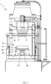
- an injection stretch blow molding machine 1 may be configured to include three stages: an injection molding section 3 that injects a molten resin from an injection apparatus 2 to injection-mold preforms; a stretch blow molding section 5 that obtains hollow molded bodies by stretching and blowing the preforms, having been released from an injection molding mold 4 of the injection molding section 3, using a blow molding mold; and an ejecting section 6 that releases the hollow molded bodies from the blow molding mold of the stretch blow molding section 5 and sends the hollow molded bodies to the outside of the molding machine.
- the above-described injection stretch blow molding machine 1 includes lip molds 7 at three places in a rotary plate 8.
- the lip mold 7 intermittently moves so as to sequentially correspond to the positions of the injection molding section 3, the stretch blowmolding section 5, and the ejecting section 6.
- the lip mold 7 holding preforms in the injection molding section 3 conveys the preforms to the subsequent stretch blow molding section 5.
- the lip mold 7 holding the hollow molded bodies molded in the stretch blow molding section 5 conveys the hollow molded bodies to the subsequent ejecting section 6.
- the lip mold 7 having released the hollow molded bodies in the ejecting section 6 moves to the subsequent injection molding section 3. In this manner, such hollow molded bodies are produced in a continuous manner.
- the above-described injection molding section 3 of the injection stretch blow molding machine 1 includes: the injection molding mold 4 including a multi-cavity mold for injection-molding preforms; and a hot runner apparatus 9, over which the injection molding mold 4 is disposed, that is configured to branch the molten resin fed from the injection apparatus 2 and send the branched molten resin to preform molding portions of the injection molding mold 4.
- the above-described lip mold 7 configured to undertake roles of forming outer peripheral surface shapes of mouth portions of the preforms and conveying the preforms and the hollow molded bodies with their mouth portions being held; a cavity mold 10 configured to form outer peripheral surface shapes of body portions and outer surface shapes of bottom portions; and core molds 11 each configured to form an inner surface shape of the preform over an area from the mouth portion to the bottom portion are combined together in the above-described injection molding mold 4.
- mold clamping of the injection molding mold 4 is done by overlaying the lip mold 7 on the top of the cavity mold 10 while inserting the core molds 11 descending from above into the cavity mold 10 so as to pass through the centers of the lip molds 7.
- the molten resin is injected into the preform molding portions from the hot runner apparatus 9 through a gate 12 provided in a lower part of the cavity mold 10, and the preform molding portions are filled from the lower ends thereof with the molten resin.
- mold opening is done by lifting the core mold 11 and upwardly moving the lip mold 7 supporting the mouth portions of the preforms, thereby upwardly releasing the preforms from the cavity mold 10.
- the preforms are then conveyed to the subsequent stretch blow molding section 5 by the lip mold 7.
- the injection molding mold 4 used for the injection molding of preforms is a multi-cavity mold.
- hot runner apparatus 9 over which the injection molding mold 4 is disposed, hot runner nozzles 13 corresponding to the number of the preform molding portions are vertically provided on a hot runner block 14.
- a runner i.e., a pipe line through which the molten resin passes
- Patent Literature 2 a runner (i.e., a pipe line through which the molten resin passes) is branched into a plurality of sections as shown in Patent Literature 2, for example.
- the hot runner apparatus 9 into which the molten resin is horizontally fed from the injection apparatus 2 includes: the above-described plurality of hot runner nozzles 13; a horizontal runner portion 15 disposed below the hot runner nozzles 13 along a row direction of the hot runner nozzles 13; vertical runner portions 16 upwardly extending from the horizontal runner portion 15 so as to be continuous with the hot runner nozzles 13; and an introducing runner portion 18 disposed horizontally from an introducing port 17 so as to be continuous with the horizontal runner portion 15 as shown in FIGS. 4 and 5 .
- the horizontal runner portion 15, the vertical runner portions 16, and the introducing runner portion 18 are formed in the above-described hot runner block 14.
- the introducing port 17 of the introducing runner portion 18 is an opening of a main nozzle 19 on the side of the injection apparatus 2, against which an injection nozzle of the injection apparatus 2 is allowed to abut.
- the molten resin fed from the injection apparatus 2 having an injection direction in a horizontal direction is guided toward the horizontal runner portion 15 by the main nozzle 19 while keeping the horizontal injection direction.
- the molten resin having entered the horizontal runner portion 15 moves to the vertical runner portions 16.
- the vertical runner portions 16 further guide the molten resin to the hot runner nozzles 13 each having an upward injection direction.
- the molten resin is horizontally fed to the hot runner apparatus 9 by the injection apparatus 2 in the injection stretch blow molding machine 1.
- the molten resin branches and the flow of the molten resin is changed to a vertically upward direction.
- the molten resin injected by the hot runner apparatus 9 is injected into the respective preform molding portions of the injection molding mold 4.
- a plurality of preforms with their mouth portions positioned on an upper side thereof are thus molded while the preform height direction corresponds to the vertical direction.
- the preforms are released by carrying out the mold opening in the injection molding section 3 as discussed above.
- the preforms are then conveyed to the subsequent stretch blow molding section 5.
- FIG. 6 schematically shows the runner extending from the introducing port 17 to the hot runner nozzles 13 in the above-described hot runner apparatus 9 used to obtain a plurality of preforms simultaneously.
- the horizontally-disposed single introducing runner portion 18 as shown in the figure is continuous with a central portion of the horizontal runner portion 15 disposed along the array direction of the hot runner nozzles 13 so as to make a right angle to the length direction of the horizontal runner portion 15.
- the portion at which the introducing runner portion 18 is continuous with the horizontal runner portion 15 is configured as a T-shaped branching pipe line 20. Taking the central portion of the horizontal runner portion 15 as a center position, each half of the horizontal runner portion 15 separated from the center position is branched into the vertical runner portions 16 toward the vertically upward direction.
- the molten resin 21 has the following characteristics as described also in Patent Literature 2 (from the lower right column on page 2 to the upper left column on page 3), for example: a resin in an outer peripheral ring-shaped region 23 slidably in contact with a pipe wall of the introducing runner portion 18 has a higher temperature due to shear heat generation and thus has a lower viscosity as compared to a resin in a central region 22 of the molten resin 21.
- the molten resin 21 moves through the introducing runner portion 18 with a lower temperature and higher viscosity resin 24 in the central region 22 being surrounded by a higher temperature and lower viscosity resin25 in the ring-shaped region 23 , and reaches the above-described branching pipe line 20 (see FIG. 7 (elevation surface a)).
- the molten resin 21 is divided into two portions by the above-described branching pipe line 20.
- the divided molten resin portions move in directions opposite to each other along the length direction of the horizontal runner portion 15 from the position of the branching pipe line 20.
- the lower temperature and higher viscosity resin 24 is divided in the length direction of the horizontal runner portion 15, and the divided lower temperature and higher viscosity resin portions move in the directions opposite to each other.
- the higher temperature and lower viscosity resin 25 in the ring-shaped region 23 is also divided into two. These divided portions form two arc-like regions 26, and move in the directions opposite to each other along the length direction of the horizontal runner portion 15 (see FIG. 7 (planar surface b)).
- the higher temperature and lower viscosity resin 25 in the arc-like region 26 is located on the side closer to the introducing port 17 of the hot runner block 14 and the remaining region is occupied by the lower temperature and higher viscosity resin 24.
- the lower temperature and higher viscosity resin 24 and the higher temperature and lower viscosity resin 25 both start to move in the length direction of the horizontal runner portion 15 from the position of the branching pipe line 20.
- the molten resin 21 moving in the length direction of the horizontal runner portion 15 causes shear heat generation in the resin present along the pipe wall of the horizontal runner portion 15.
- the region occupied by the higher temperature and lower viscosity resin 25 on the side of the horizontal runner portion 15 closer to the introducing port 17 of the hot runner block 14 becomes wider in the cross-sectional direction of the pipe line.
- the molten resin 21 laterally moving through the horizontal runner portion 15 is partially separated and moves upwardly into the vertical runner portions 16 branching from intermediate positions of the horizontal runner portion 15.
- the molten resin 21 laterally moving through the horizontal runner portion 15 also moves upwardly into the vertical runner portions 16 continuously rising from end positions of the horizontal runner portion 15.
- the flow of the molten resin 21 is changed to the upward direction from the horizontal runner portion 15 to the vertical runner portions 16.
- a region occupied by the higher temperature and lower viscosity resin 25 on the side closer to the introducing port 17 of the hot runner block 14 becomes wider in the cross-sectional direction of the pipe line as with the case of the horizontal runner portion 15.
- the molten resin 21 moving through the vertical runner portion 16 and reaching the hot runner nozzle 13 is injected from the hot runner nozzle 13 and filled into the preform molding portion of the injection molding mold 4.
- the preform molding portion filled with the molten resin 21 has a distribution in which the higher temperature and lower viscosity resin 25 is located in a biased manner in a part corresponding to the side closer to the introducing port 17 of the hot runner block 14.
- a preform is released only after the preform is cooled down in the injection molding section so as to lower the temperature of the preform.
- the preform is then conveyed to the subsequent stretch blow molding section to undergo stretching and blowing.
- a plurality of hollow molded bodies are produced for each cycle by releasing a plurality of preforms arranged in a row from the multi-cavity injection molding mold at a time and by simultaneously stretching and blowing the plurality of preforms in the stretch blow molding section.
- a problem further arises in that the degrees of unevenness in the thicknesses of the body portions of the hollow molded bodies in their circumferential direction are not uniform, and vary greatly, in the molding row direction of the hollow molded bodies.
- the aim of the present invention is to enable a molten resin to be fed from a hot runner apparatus into the preform molding portions of the injection molding mold in the above-described injection stretch blow molding machine without a higher temperature and lower viscosity resin being present in a biased manner in its circumferential direction. It is an object of the present invention to enable preforms having no biased portion of a higher temperature and lower viscosity resin in their circumferential direction to be injection-molded and thus enable timing for releasing the preforms to be advanced so as to start molding of hollow molded bodies earlier.
- the present invention has been made in light of the above-described problem.
- the above-described problem is solved by an injection stretch blow molding machine according to independent claim 1.
- a method for branching a molten resin in the hot runner apparatus in such an injection blow molding machine is provided in claim 6.
- the dependent claims relate to advantageous embodiments.
- the injection molding mold may preferably be a molding mold for molding preforms with their mouth portions positioned on an upper side thereof by being injected and filled with a molten resin upwardly fed by the hot runner nozzles .
- the introducing runner portion (18) of the hot runner apparatus is bent toward the horizontal runner portion (15) after reaching the elevation plane (A: a virtual elevation plane) passing through the position of the horizontal runner portion (15) in the up-and-down direction as shown in FIG. 19 .
- the introducing runner portion (18) further extends from the bent portion toward the intermediate portion (15a) of the horizontal runner portion (15) in the above-described elevation plane (A) so as to be continuous with the intermediate portion (15a) in the elevation plane (A).
- the moving direction of the higher temperature and lower viscosity resin branched by the movement into the horizontal runner portion is biased toward the length direction of the horizontal runner portion along the pipe wall of the upper part or lower part of the horizontal runner portion.
- the molten resin moves through the horizontal runner portion with the higher temperature and lower viscosity resin moving along the pipe wall of the upper part or the pipe wall of the lower part of the horizontal runner portion, and the molten resin moving through the horizontal runner portion is fed into the vertical runner portions.
- a higher temperature and lower viscosity resin is generated in a ring-shaped region in the outer peripheral portion of the molten resin having higher temperature along the pipe wall of the lower part (since the portion originally corresponds to the portion of the above-described branched higher temperature resin) as the molten resin moves . Since the molten resin having such a state is branched and fed into the vertical runner portion, no temperature unevenness is generated in the circumferential direction of the horizontal cross-section for the molten resin passing through the vertical runner portion.
- the preform since a preform is injection-molded without the higher temperature and lower viscosity resin being significantly biased circumferentially in the horizontal cross-sectional direction, the preform has no temperature unevenness. Therefore, even when a hollow molded body is blow molded after advancing timing for releasing the preform, no significant unevenness in thickness is generated in the circumferential direction of the hollow molded body.
- FIGS. 8 to 19 The present invention will be described next in detail with reference to embodiments shown in FIGS. 8 to 19 . Note that elements overlapping with those in the conventional example shown in FIGS. 4 to 7 will be denoted by the same reference numerals and the description thereof will be omitted.
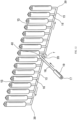
- FIGS. 8 and 9 illustrate a hot runner apparatus 9 over which an injection molding mold 4 in an injection molding section 3 of an injection stretch blow molding machine 1 according to the present invention is disposed.
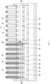
- sixteen hot runner nozzles 13 having a vertically upward injection direction are vertically provided on an upper part of a hot runner block 14.
- the reference numeral "27” denotes a hot runner fixing plate
- the reference numerals "28” and “29” denote hot runner pressure receiving plates disposed above the hot runner fixing plate 27 for supporting the hot runner block 14.
- a shutoff pin 30 for opening and closing a nozzle orifice of the hot runner nozzle 13 is disposed in a resin passage portion inside the hot runner nozzle 13 so as to pass through the hot runner block 14 in the up-and-down direction from a height position corresponding to a lower side of the hot runner pressure receiving plate 28.
- a pin fixing plate 32 supported by a shutoff piston 31 is disposed at the height position corresponding to the lower side of the hot runner pressure receiving plate 28.
- the pin fixing plate 32 moves in the up-and-down directions by motions of the shutoff piston 31. Note that the hot runner pressure receiving plate 28 is disposed so as not to interfere with the shutoff pin 30.
- the lower end of the shutoff pin 30 is supported by the pin fixing plate 32.
- the shutoff pin 30 moves in the up-and-down directions by motions of the shutoff piston 31.
- the nozzle orifice is opened and closed by the up and down movements of the shutoff pin 30.
- FIG. 8 described above also illustrates the injection molding mold 4 attached to an upper part of the hot runner apparatus 9.
- the injection molding mold 4 shown in the figure is in a mold-closed state.
- a cavity mold 10 of the injection molding mold 4 is fixed to the hot runner apparatus 9 via a cavity fixing plate 33 .
- a rotary plate 8 is at a descent position during the mold closing as discussed above so that a lip mold 7 supported by the rotary plate 8 is overlaid on the cavity mold 10.
- a core mold 11 supported by an injection core fixing plate 34 is also at a descent position so that a preform inner surface forming part of the core mold 11 is located inside of the lip mold 7 and the cavity mold 10.
- a gate 12 at the lower end of the cavity mold 10 is opposed to the nozzle orifice of the above-described hot runner nozzle 13, and a molten resin injected upwardly from the hot runner nozzle 13 is filled into a preform molding portion in a direction from its lower side toward its upper side via the gate 12.
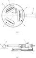
- the center of the injection molding section 3 is located on a radial direction of the rotary plate passing through the center of the injection stretch blow molding machine 1 (the arrangement center among the injection molding section 3, a stretch blow molding section 5, and an ejecting section 6) (see FIG. 2 ).
- the length direction of the injection molding mold 4 in which preform molding portions are arranged in a row as a 16-cavity mold and the length direction of the above-described hot runner apparatus 9 in which the 16 hot runner nozzles 13 are arranged in a row are set so as to be perpendicular to the above-described radial direction of the rotary plate.
- the injection direction of an injection apparatus 2 coincides with the above-described radial direction of the rotary plate in the injection stretch blow molding machine 1 passing through the center of the hot runner apparatus 9.
- An injection nozzle of the injection apparatus 2 is connected to an introducing port 17 located at the center of the hot runner block 14 in its length direction.
- the introducing port 17 of the hot runner block 14 is an opening against which the nozzle of the injection apparatus 2 is allowed to abut as with the above-discussed conventional example.
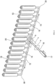
- the hot runner block 14 includes: a horizontal runner portion 15 disposed below the hot runner nozzles 13 along the row direction of the hot runner nozzles 13 (the length direction of the hot runner block 14); sixteen vertical runner portions 16 extending upwardly from the horizontal runner portion 15 so as to be continuous with the hot runner nozzles 13; and an introducing runner portion 18, including a passage of a main nozzle 19, for guiding the molten resin from the introducing port 17 toward the horizontal runner portion 15.
- shutoff pin 30 of the hot runner apparatus 9 completely passes through a pipe line of the horizontal runner portion 15 in the vertical direction (the up-and-down direction) and passes through the center of a pipe line of the vertical runner portion 16 rising from the horizontal runner portion 15 in the vertical direction so as to be disposed in a passage inside the hot runner nozzle 13 (nozzle-axis center) (see FIGS. 8 and 9 ).
- the hot runner block 14 has a rectangular transverse cross-sectional shape. As shown in the transverse cross-section, the hot runner block 14 is pierced along the length direction of the horizontal runner portion 15 so as to provide insertion holes 35 at a total of four positions : two positions above the horizontal runner portion 15 provided on the side where the introducing port 17 is provided and on its opposite side, and two positions below the horizontal runner portion 15 provided on the side where the introducing port 17 is provided and on its opposite side. Bar heaters 36 are inserted into the insertion holes 35.
- the bar heater 36 is disposed along the length direction of the horizontal runner portion 15. Furthermore, the bar heaters 36 are disposed at an equal distance from the horizontal runner portion 15. The hot runner block 14 is heated by these bar heaters 36, and the molten resin moving through such a hot runner block 14 is heated by the hot runner block 14 having an increased temperature.
- the present invention is not limited to the shape of the hot runner block 14 shown in the embodiment.
- its transverse cross-sectional shape may be circular as illustrated in FIG. 4 for the description of the conventional technique.
- a hot runner apparatus having a hot runner block with a circular transverse cross-section can employ a cover-like heater externally surrounding the hot runner block.
- the direction of the passage of the main nozzle 19 (passage for the molten resin injected by the injection apparatus), which is a part of the introducing runner portion 18, is set to a direction perpendicular to the length direction of the horizontal runner portion 15.
- a pipe line from the introducing port 17 to the horizontal runner portion 15 extends to a position below the horizontal runner portion 15.
- the pipe line of the introducing runner portion 18 reaches the position below the horizontal runner portion 15 corresponding to a portion of a virtual elevation plane A passing through the position of the horizontal runner portion 15 in the up-and-down direction along the horizontal runner portion 15.
- the pipe line of the introducing runner portion 18 further bends upwardly toward the horizontal runner portion 15 in an L shape after reaching the portion below the horizontal runner portion 15, i.e. , the above-described elevation plane A.
- the pipe line extends upwardly from a bent portion 37, which is the bent portion of the pipe line, so as to be continuous with a lower part of an intermediate portion 15a of the horizontal runner portion 15 in the elevation plane A.
- a T-shaped branching pipe line 20 is provided in a connection portion between the upwardly-bent pipe line of the introducing runner portion 18 and the pipe line of the horizontal runner portion 15.
- the above-described branching pipe line 20 is placed in the intermediate portion 15a of the horizontal runner portion 15 corresponding to a central portion of the horizontal runner portion 15 in its length direction.
- Eight vertical runner portions 16 extend upwardly from, and are continuous with, each half of the horizontal runner portion 15 extending from the branching pipe line 20.
- the molten resin horizontally injected by the injection apparatus 2 is fed into the introducing runner portion 18 through the main nozzle 19.
- a higher temperature and lower viscosity resin 25 is generated in a ring-shaped region 23 corresponding to an outer peripheral portion of the molten resin 21 due to shear heat generation as discussed above.
- the molten resin 21 in which the portion of a central region 22 where a lower temperature and higher viscosity resin 24 is distributed is surrounded by the higher temperature and lower viscosity resin 25 in the ring-shaped region 23 moves toward the horizontal runner portion 15 and reaches the branching pipe line 20.
- higher temperature and lower viscosity resin 25 and the lower temperature and higher viscosity resin 24 together constitute the molten resin 21 moving through the pipe line.
- the terms “higher” and “lower” are expressed by contrasting the temperature of resin with the viscosity of the resin.
- the higher temperature and lower viscosity resin and the lower temperature and higher viscosity resin are not defined on the basis of a particular temperature and a particular viscosity.
- the molten resin 21 is divided when the molten resin 21 reaches the branching pipe line 20 and moves in the length direction of the horizontal runner portion 15.
- the divided molten resin portions move through the respective halves of the horizontal runner portion 15 so as to move away from each other along the length direction of the horizontal runner portion 15.
- the branching pipe line 20 causes the portion used to be the central region 22 comprising the lower temperature and higher viscosity resin 24 in the introducing runner portion 18 to branch into two regions 38 and also causes the higher temperature and lower viscosity resin 25 in the above-describedring-shapedregion23 to branch into two.
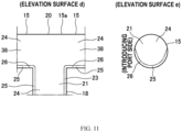
- two arc-like regions 26 are formed, and the above-described higher temperature and lower viscosity resin 25 is located in these regions ( FIG. 11 (elevation surface d)).
- the branching pipe line bends the moving direction of the higher temperature and lower viscosity resin 25 that forms the arc-like region 26 so as to go along a pipe wall of the horizontal runner portion 15 with which the introducing runner portion 18 is continuous , i.e. , the pipe wall of a lower part of each half of the horizontal runner portion 15, and thus causes the moving direction to be biased toward the length direction of the pipe wall of such a lower part.
- the higher temperature and lower viscosity resin 25 is distributed along the pipe wall of the lower part of each half of the horizontal runner portion 15 as the arc-like region 26, and the lower temperature and higher viscosity resin 24 (resin constituting the region 38) is distributed over the remaining region ( FIG. 11 (elevation surface e)).
- the molten resin 21 moving through each half of the horizontal runner portion 15 in its length direction is branched and fed into the vertical runner portion 16.
- the molten resin 21 is also fed into the vertical runner portion 16 extending upwardly from an end of each half of the horizontal runner portion 15.
- the ring-shaped region 23 in which the higher temperature and lower viscosity resin 25 is distributed develops in the outer peripheral portion of the molten resin 21 whose lower part has a higher temperature (the temperature of the lower part becomes high since the above-described higher temperature and lower viscosity resin 25 is located along the pipe wall of the lower part of the horizontal runner portion 15).
- molten resin 21 is separated from the laterally moving molten resin 21 and fed into the vertical runner portion 16 while keeping a vertically stacked form in which an upper part thereof is occupied by the lower temperature and higher viscosity resin 24 and the higher temperature and lower viscosity resin 25 is located in a lower part thereof as shown in the above-described elevation surface e. It is also believed that the molten resin 21 passing a branch position without branching moves through the horizontal runner portion 15 also with the distribution shown on the elevation surface e (such resin movement is deduced from comparison results to be described later).
- the ring-shaped region 23 comprising the higher temperature and lower viscosity resin 25 is generated slightly in the outer peripheral portion of the molten resin 21. Since the length of the passage is short, the higher temperature and lower viscosity resin 25 can be prevented from being present in a significantly biased state in the outer peripheral portion in the cross-sectional direction of the pipe line of the vertical runner portion 16.
- the pipe line of the vertical runner portion 16 disposed at an end of the horizontal runner portion 15 is extended upwardly via a bent portion 39 formed by bending the pipe line of the end of the horizontal runner portion 15 upwardly.
- a portion transformed into the higher temperature and lower viscosity resin 25 due to shear heat generation increases accordingly in the portion occupied by the lower temperature and higher viscosity resin 24 (in the cross-sectional direction of the pipe line) .
- the portion already occupied by the higher temperature and lower viscosity resin 25 has a small amount of shear heat generation due to its low viscosity.
- the proportion of the occupying higher temperature and lower viscosity resin 25 is increased in the cross-sectional direction of the pipe line, and a biased degree of the higher temperature and lower viscosity resin 25 is diminished. It is believed that the molten resin 21 having such a state is fed into the vertical runner portion 16, and thus the higher temperature and lower viscosity resin 25 is not located in a significantly biased manner, or is scarcely present in a biased manner, in the cross-sectional direction of the pipe line also in the vertical runner portion 16.
- the higher temperature and lower viscosity resin 25 is not present in a significantly biased manner in the cross-sectional direction of the pipe line.
- the molten resin 21 is injected and filled into the respective preform molding portions of the above-described injection molding mold 4 from the above-described vertical runner portions 16 via the hot runner nozzles 13.
- the injection molding mold 4 is a molding mold for molding preforms with their mouth portions positioned on an upper side thereof .
- the molten resin 21 is injected into sixteen preform molding portions by corresponding hot runner nozzles 13, respectively.
- the molten resin 21 is injected and filled upwardly via the gate 12.
- the higher temperature and lower viscosity resin 25 is scarcely present in a biased manner in the circumferential direction of the cross-section of the pipe line.
- the higher temperature and lower viscosity resin 25 is not located in a significantly biased manner in the circumferential direction of the horizontal cross-section of the preform molding portion. Therefore, a preform having no significant temperature unevenness in the circumferential direction can be molded in every preform molding portion.
- temperature difference tends to increase in the circumferential direction in each of preforms corresponding to the positions of the vertical runner portions 16 at both ends, but such temperature difference can be regarded to fall within a range manageable on the part of the injection molding mold.
- the pipe line of the introducing runner portion 18 is continuous (in the elevation plane A) with the pipe wall of the lower part of the central portion of the horizontal runner portion 15 after reaching the elevation plane A and bending upwardly in an L shape.
- the present invention is not limited to the introducing runner portion 18 continuous with the lower part of the horizontal runner portion 15.
- FIG. 12 shows a second example in which an introducing runner portion 18 is continuous with a central portion of a horizontal runner portion 15.
- the second example differs from the first example in that the introducing runner portion 18 is continuous with a pipe wall of an upper part of the horizontal runner portion 15 as will be described below.
- the other elements in the second example are the same as those in the first example.
- the direction of the introducing runner portion 18 is set so as to be perpendicular to the length direction of the horizontal runner portion 15 as with the first example.
- the pipe line of the introducing runner portion 18 reaches an elevation plane A, and then extends downwardly in the above-described elevation plane A from a bent portion 40 bent in an L shape at the position above the horizontal runner portion 15, so as to be continuous with the pipe wall of the upper part of the central portion of the horizontal runner portion 15.
- a T-shaped branching pipe line 20 is provided in a connection portion between the pipe line of the introducing runner portion 18 and a pipe line of the horizontal runner portion 15 as with the above-described first example.
- the molten resin 21 horizontally injected by the injection apparatus 2 is fed into the introducing runner portion 18 through a main nozzle 19, and the molten resin 21 reaches the branching pipe line 20.
- the molten resin 21 is divided when the molten resin 21 moves into the length direction of the horizontal runner portion 15.
- the divided molten resin portions move through respective halves of the horizontal runner portion 15 so as to move away from each other along the length direction of the horizontal runner portion 15.
- the branching pipe line 20 causes the portion used to be a central region 22 comprising a lower temperature and higher viscosity resin 24 in the introducing runner portion 18 to branch into two regions 38 and also causes a higher temperature and lower viscosity resin 25 in the above-described ring-shaped region 23 to branch into two.
- two arc-like regions 26 are formed, and the above-described higher temperature and lower viscosity resin 25 is located in these regions ( FIG. 13 (elevation surface f)).
- the branching pipe line 20 bends the moving direction of the higher temperature and lower viscosity resin 25 that forms the arc-like region 26 so as to go along the pipe wall of the upper part of each half of the horizontal runner portion 15, and thus causes the moving direction to be biased toward the length direction of the pipe wall of the upper part.
- the higher temperature and lower viscosity resin 25 is located along the pipe wall of the upper part of each half of the horizontal runner portion 15 as the arc-like region 26, and the lower temperature and higher viscosity resin 24 (resin constituting the region 38) occupies the remaining region.
- the molten resin 21 moving through each half of the horizontal runner portion 15 is branched and fed into the vertical runner portion 16.
- the molten resin 21 is also fed into the vertical runner portion 16 extending upwardly from an end of each half of the horizontal runner portion 15.
- the moving direction of the higher temperature and lower viscosity resin 25 that forms the above-described arc-like region 26 is biased toward the length direction of the horizontal runner portion 15 along the pipe wall of the upper part of each half of the horizontal runner portion 15.
- the ring-shaped region 23 in which the higher temperature and lower viscosity resin 25 is located develops in the outer peripheral portion of the molten resin 21. It is believed that for each shot, a part of the molten resin 21 is separated from the laterally moving molten resin 21 and fed into the vertical runner portion 16 while keeping a vertically stacked form in which a lower part thereof is occupied by the lower temperature and higher viscosity resin 24 and the higher temperature and lower viscosity resin 25 is located in an upper part thereof (the vertically inverted form of the distribution shown on the elevation surface e) .
- the molten resin 21 passing a branch position without branching moves through the horizontal runner portion 15 while keeping the vertically stacked form in which the lower part thereof is occupied by the lower temperature and higher viscosity resin 24 and the higher temperature and lower viscosity resin 25 is located in the upper part thereof.
- the ring-shaped region 23 comprising the higher temperature and lower viscosity resin 25 is generated slightly in the outer peripheral portion of the molten resin 21. Since the length of the passage is short, the higher temperature and lower viscosity resin 25 can be prevented from being present in a significantly biased manner in the outer peripheral portion in the cross-sectional direction of the pipe line of the vertical runner portion 16.
- the proportion of the occupying higher temperature and lower viscosity resin 25 is increased in the cross-sectional direction of the pipe line, and a biased degree of the higher temperature and lower viscosity resin 25 is diminished. It is believed that the molten resin 21 having such a state is fed into the vertical runner portion 16 at the end, and thus the higher temperature and lower viscosity resin 25 is not located in a significantly biased manner, or is scarcely present in a biased manner, in the cross-sectional direction of the pipe line also in the vertical runner portion 16.
- the higher temperature and lower viscosity resin 25 is not present in a significantly biased manner in the cross-sectional direction of the pipe line.
- the molten resin 21 is injected and filled into respective preform molding portions of an injection molding mold 4 from the above-described vertical runner portions 16 via hot runner nozzles 13.
- the higher temperature and lower viscosity resin 25 is not located in a significantly biased manner in the circumferential direction of the horizontal cross-section of the preform molding portion as with the first example. Therefore, a preform having no significant temperature unevenness in the circumferential direction can be molded in every preform molding portion.
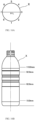
- Values obtained by measuring thicknesses of body portions of PET bottles molded according to a conventional example are shown in a table of FIG. 14
- values obtained by measuring thicknesses of body portions of PET bottles molded according to an example are shown in a table of FIG. 15 .
- the conventional example employs a hot runner apparatus 9 in which an introducing runner portion 18 is continuous with a central portion of a horizontal runner portion 15 in its length direction from a traverse direction perpendicular to the horizontal runner portion 15 .
- the PET bottles were produced using an injection stretch blow molding machine 1 in which the hot runner apparatus 9 was disposed in an injection molding section 3.
- the example employs a hot runner apparatus 9 in which a pipe line of an introducing runner portion 18 is bent in an L shape and the pipe line extending from the bent portion is continuous with a central portion of a horizontal runner portion 15 in its length direction from below so as to be perpendicular to the horizontal runner portion 15.
- the PET bottles were produced using an injection stretch blow molding machine 1 in which the hot runner apparatus 9 is disposed in an injection molding section 3.
- An injection molding mold 4 used in the comparative example and the example is a molding mold for obtaining sixteen preforms arranged in a row.
- Used resin amounts for the PET bottles in the comparative example and the PET bottles in the example were each 24.0 g.
- the PET bottles were produced, using the three-station injection stretch blow molding machines, by: injecting a molten resin into preform molding portions of the injection molding mold; releasing the preforms early at a stage not impairing the shapes of the preforms and directly conveying the preforms to a stretch blow molding section from the injection molding section; and stretch-blow molding the preforms while being cooled.
- Thicknesses of a body portion X of a PET bottle produced as a hollow molded body were measured at eight positions in the circumferential direction thereof .
- Numbers 1 to 8 shown in the tables represent thickness measurement positions in the horizontal cross-section of the body portion.
- the number "1" corresponds to the side of an injection apparatus, and thicknesses are measured at an interval of 45 degrees in the circumferential direction.
- thicknesses are also measured at four positions along the height direction of the body portion X of the PET bottle.
- a line at the center of the cross-section of the body portion in FIG. 16 (A) and a line at the center of the side surface of the container in FIG. 16 (B) both indicate a parting line position in a blow mold.
- the measured PET bottles are those molded from preforms molded in eight preform molding portions corresponding to a half of the horizontal runner portion in the hot runner apparatus among the sixteen preform molding portions of the injection molding mold.
- a molding position corresponding to the side of the above-described branching pipe line in the hot runner apparatus is denoted by H (see Fig. 10 ) .
- Molding positions are denoted by I, ..., P so as to correspond to the arrangement order from the "H" of the preform molding portions of the injection molding mold.
- the table entry title "Height” represents a height measured from the bottom of a PET bottle in its height direction
- the table entry title "unit” represents a unit for a measured value
- the table entry title "Ave. " represents an average value
- the table entry title "Differ.” represents a difference between a maximum value and a minimum value.
- a numerical value in the last line under the above-described table entry title "Differ.” represents an average “Differ.” value of the four measured heights.
- the PET bottles molded according to the comparative example are evaluated as follows .
- the PET bottles molded according to the example are evaluated as follows.
- the above-described example employs the hot runner apparatus 9 in which the introducing runner portion 18 is continuous with the horizontal runner portion 15 from below in an elevation plane A. It is believed that the similar results can be obtained also by employing the hot runner apparatus 9 in the above-described second example since the introducing runner portion 18 is continuous with the horizontal runner portion 15 from above in the elevation plane A, and the molten resin 21 fed from the introducing runner portion 18 branches and the branched portions of the molten resin 21 move along the length direction of the horizontal runner portion 15 so as to move away from each other.
- the hot runner apparatuses exemplified in the first example and the second example are those manufactured for obtaining an even number of preforms . It has been described that the introducing runner portion is continuous with the central portion of the horizontal runner portion from below (the first example) or from above (the second example).
- the present invention is not limited to the configurations shown in the first example and the second example.
- the present invention can be applied also to a hot runner apparatus in which an odd number of hot runner nozzles are vertically provided on a hot runner block.
- FIG. 17 illustrates a hot runner apparatus 9 including an odd number of hot runner nozzles 13 as a third example.
- FIG. 17(a) schematically illustrates the hot runner apparatus 9 including the five hot runner nozzles 13 as viewed from the side of a main nozzle.
- FIG. 17(b) schematically illustrates the portion of a branching pipe line 20.
- a single hot runner nozzle 13 is provided vertically at a central portion of a horizontal runner portion 15 in its length direction.
- An introducing port 17 of the hot runner apparatus 9 is located at a central portion of a hot runner block 14 in its length direction.
- a pipe line of an introducing runner portion 18 extends from the side of the introducing port 17 in a direction perpendicular to the length direction of the horizontal runner portion 15, bends in an oblique direction toward one end side immediately before reaching an elevation plane A, and reaches a position below the horizontal runner portion 15 on the above-described elevation plane A from the bent portion 41.
- the pipe line of the introducing runner portion 18 further bends at the portion having reached the elevation plane A, and extends from the bent portion 42 toward the horizontal runner portion 15 in the elevation plane A, so as to be continuous with a portion of a pipe wall of a lower part of the horizontal runner portion 15.
- the portion at which the introducing runner portion 18 is continuous with the horizontal runner portion 15 is configured as the T-shaped branching pipe line 20.
- the branching pipe line 20 in the third example is not located in the central portion of the horizontal runner portion 15 in its length direction.
- the above-described branching pipe line 20 is provided so as to be displaced toward the one end side of the horizontal runner portion 15 from the central portion of the horizontal runner portion 15 and be located at an intermediate portion 15a between two vertical runner portions 16.
- the portion at which the introducing runner portion 18 is connected to the horizontal runner portion 15 preferably corresponds to the central portion of the horizontal runner portion 15 in its length direction, such a portion may be located at a position displaced from the central portion as needed. Also when the introducing runner portion 18 is continuous with a portion of a pipe wall of an upper part of the horizontal runner portion 15 as in the second example, the introducing runner portion 18 may be connected to a position displaced from the central portion of the horizontal runner portion 15.
- the hot runner apparatus 9 of the third example also works in a manner similar to when the hot runner apparatuses 9 shown in the first example and the second example are incorporated into the injection stretch blow molding machines 1 and hollow molded bodies are produced at advanced timing for releasing preforms. More specifically, by disposing the T-shaped branching pipe line 20 in the intermediate portion displaced from the central portion of the horizontal runner portion 15 so that a molten resin 21 from the introducing runner portion 18 is fed thereinto, branching of the molten resin 21 can be made as with the first example and the second example. Thus, favorable hollow molded bodies can be produced also when the hot runner apparatus 9 shown in the third example is incorporated into an injection stretch blow molding machine 1 and hollow molded bodies are produced at advanced timing for releasing preforms.
- FIG. 18 illustrates a fourth example.
- FIG. 18(a) schematically illustrates a hot runner apparatus 9 including an odd number of hot runner nozzles 13 as viewed from the side of a main nozzle.
- FIG. 18 (b) schematically illustrates the portion of a branching pipe line 20.
- an introducing runner portion 18 in the hot runner apparatus 9 shown as the fourth example is provided so as to be displaced toward one end side of a horizontal runner portion 15 from a central portion of the horizontal runner portion 15 and be continuous with an intermediate portion 15a between two vertical runner portions 16.
- a pipe line of the introducing runner portion 18 extends from the side of an introducing port 17 in a direction perpendicular to the length direction of the horizontal runner portion 15 and reaches a position below the horizontal runner portion 15 on an elevation plane A.
- the pipe line of the introducing runner portion 18 bends at the portion having reached the elevation plane A, and extends from the bent portion 43 in an obliquely upward direction in the elevation plane A, so as to be continuous with a portion of a pipe wall of a lower part of the horizontal runner portion 15.
- the branching pipe line 20 is provided in a Y shape in the portion where the introducing runner portion 18 is continuous with the horizontal runner portion 15 in the intermediate portion 15a of the horizontal runner portion 15 so as to conform with the introducing runner portion 18 extending in the obliquely upward direction.
- the branching pipe line 20 provided in the portion where the introducing runner portion 18 is continuous with the horizontal runner portion 15 in the present invention is not limited to those having a T shape as shown in the first to third examples.
- the branching pipe line 20 may have a Y shape as shown in the fourth example.
- the Y-shaped branching pipe line 20 is provided in the intermediate portion displaced from the central portion of the horizontal runner portion 15, and the introducing runner portion 18 is continuous with the horizontal runner portion 15 at the above-described intermediate portion 15a.
- branching of the molten resin 21 can be made as with the above-described examples.
- favorable hollow molded bodies can be produced as with the first to third examples also when the hot runner apparatus 9 of the fourth example is incorporated into an injection stretch blow molding machine 1 and hollow molded bodies are produced at advanced timing for releasing preforms.
- a passage for a molten resin, with which the vertical runner portion 16 is continuous, is located in a nozzle-axis center portion, and the shutoff pin 30 is provided so as to pass through the vertical runner portion 16 and the above-described passage in the nozzle-axis center portion.
- the hot runner nozzle that can be employed in the present invention is not limited to those constructed in such a manner that the position of the shutoff pin is overlapped with the entire length of the passage for a molten resin.
- a hot runner nozzle constructed in such a manner that a passage for a molten resin is provided in a portion displaced from a nozzle-axis center portion and the passage is overlapped with the position of a shutoff pin on the tip side of the nozzle as described in Japanese Patent Application Laid-Open No. Hei. 06-182815 .
Landscapes
- Engineering & Computer Science (AREA)
- Mechanical Engineering (AREA)
- Manufacturing & Machinery (AREA)
- Moulds For Moulding Plastics Or The Like (AREA)
- Blow-Moulding Or Thermoforming Of Plastics Or The Like (AREA)
Claims (6)
- Spritzstreckblasmaschine (1), welche umfasst:einen Spritzgießabschnitt (3), der ein geschmolzenes Harz (21) aus einer Spritzvorrichtung (2) zu Spritzguss-Preformen spritzt;einen Streckblasabschnitt (5), welcher durch Streckblasen der Preformen, nachdem diese aus einer Spritzgießform des Spritzgießabschnitts (3) gelöst wurden, unter Verwendung einer Blasform hohle Formkörper herstellt; undeinen Auswurfabschnitt (6), der die hohlen Formkörper aus der Blasform des Streckblasabschnitts (5) löst und die hohlen Formkörper nach außerhalb der Blasmaschine (1) sendet, wobei
der Spritzgießabschnitt (3) oberhalb einer Heißkanalvorrichtung (9) vorgesehen ist,wobei die Heißkanalvorrichtung umfasst:mehrere Heißkanaldüsen (13), die in einer Reihe angeordnet sind und eine Spritzrichtung nach oben aufweisen;einen horizontalen Kanalabschnitt (15), der unterhalb der Heißkanaldüsen (13) entlang einer Reihenrichtung der Heißkanaldüsen (13) angeordnet ist,vertikale Kanalabschnitte (16), die sich von dem horizontalen Kanalabschnitt (15) aus nach oben erstrecken, um ein geschmolzenes Harz (21), das durch den horizontalen Kanalabschnitt (15) fließt, in die Heißkanaldüsen (13) zu leiten; undeinen Einführungskanalabschnitt (18), der in einen Zwischenabschnitt (15a) des horizontalen Kanalabschnitts (15) übergeht, um ein geschmolzenes Harz (21) von einem Einleitungsanschluss (17), in den das geschmolzene Harz (21) von einer Spritzvorrichtung (2) eingespeist wird, die eine Spritzrichtung in einer horizontalen Richtung aufweist, in Richtung des horizontalen Kanalabschnitts (15) zu leiten,wobeider Einführungskanalabschnitt (18) eine Struktur aufweist, in welcher der Einführungskanalabschnitt (18) in Richtung des horizontalen Kanalabschnitts (15) umgebogen ist, nachdem er eine Elevationsebene (A) erreicht hat, die durch eine Position des horizontalen Kanalabschnitts (15) in einer Aufwärts-Abwärts-Richtung verläuft, und in den Zwischenabschnitt (15a) des horizontalen Kanalabschnitts (15) in der Elevationsebene (A) übergeht,die Heißkanalvorrichtung (9) unter einer Spritzgießform (4) der Spritzstreckblasmaschine (1) vorgesehen ist,wobei die Spritzgießform (4) aufweist:mehrere Preform-Spritzgießabschnitte; und mehrere Angüsse (12), die in die Preform-Spritzgießabschnitte übergehen,wobei die mehreren Heißkanaldüsen (13) mit den jeweiligen Angüssen (12) verbindbar sind, unddie Heißkanalvorrichtung dazu ausgebildet ist zu ermöglichen, dass ein geschmolzenes Harz (21), das von den jeweiligen Heißkanaldüsen (13) gespritzt wird, durch die Angüsse (12) hindurch in die jeweiligen Preform-Spritzgießabschnitte eingefüllt wird,
undder Spritzgießabschnitt (3) die Spritzgießform aufweist, welche Preform-Spritzgießabschnitte aufweist, die den Heißkanaldüsen (3) entsprechen. - Spritzstreckblasmaschine (1) nach Anspruch 1, wobei der Einführungskanalabschnitt (18) in einen von einem unteren Teil und einem oberen Teil des horizontalen Kanalabschnitts (15) übergeht.
- Spritzstreckblasmaschine (1) nach Anspruch 1 oder 2, wobei ein Abschnitt, an dem der Einführungskanalabschnitt (18) in den horizontalen Kanalabschnitt (15) übergeht, als eine sich verzweigende Rohrleitung (20) ausgebildet ist und die sich verzweigende Rohrleitung (20) bewirkt, dass ein Harz, das sich in einem äußeren Umfangsabschnitt eines geschmolzenen Harzes (21) befindet, der gleitend in Kontakt mit einer Rohrwand des Einführungskanalabschnitts (18) steht, sich in zwei Richtungen aufteilt, und bewirkt, dass eine Bewegungsrichtung des aufgeteilten Harzes in Richtung einer Längsrichtung des horizontalen Kanalabschnitts (15) entlang einer Rohrwand des horizontalen Kanalabschnitts (15) auf einer Seite, in welche der Einführungskanalabschnitt (18) übergeht, beaufschlagt wird.
- Spritzstreckblasmaschine (1) nach einem der Ansprüche 1 bis 3, wobei die Struktur des Einführungskanalabschnitts (18) Temperaturungleichheiten in einem geschmolzenen Harz (21) in einer Umfangsrichtung eines horizontalen Querschnitts einer Rohrleitung des vertikalen Kanalabschnitts (16) unterdrückt, wobei das geschmolzene Harz (21) aus dem Einführungskanalabschnitt (18) über den horizontalen Kanalabschnitt (15) in die vertikalen Kanalabschnitte (16) eingeleitet wird.
- Spritzstreckblasmaschine (1) nach einem der Ansprüche 1 bis 4, wobei die Spritzgießform eine Form zum Formen von Preformen ist, mit auf einer Oberseite derselben positionierten Mundstücken, indem sie gespritzt und mit einem geschmolzenen Harz gefüllt werden, das von den Heißkanaldüsen (3) aufwärts eingespeist wird.
- Verfahren zum Verteilen eines geschmolzenen Harzes (21) in der Heißkanalvorrichtung (9) in einer Spritzstreckblasmaschine nach einem der Ansprüche 1 bis 5, zum Verteilen des geschmolzenen Harzes (21) auf die mehreren Heißkanaldüsen (13) der Heißkanalvorrichtung (9) durch horizontales Einspeisen des geschmolzenen Harzes (21) in den Einführungskanalabschnitt (18) der Heißkanalvorrichtung (9) durch die Spritzvorrichtung (2), wobei das Verfahren umfasst:Ändern einer Bewegungsrichtung des geschmolzenen Harzes (21), das in den Einführungskanalabschnitt (18) eingespeist wird und aufgrund der Scherwärmeerzeugung ein Harz mit höherer Temperatur und niedrigerer Viskosität in einem äußeren Umfangsabschnitt desselben aufweist, in eine Richtung entlang der Elevationsebene (A) ;Einspeisen des geschmolzenen Harzes (21) in den Zwischenabschnitt (15a) des horizontalen Kanalabschnitts (15) und dadurch Aufteilen einer Bewegungsrichtung des Harzes mit höherer Temperatur und niedrigerer Viskosität aus dem Zwischenabschnitt (15a) des horizontalen Kanalabschnitts (15) in zwei Richtungen entlang der Längsrichtung des horizontalen Kanalabschnitts; undBewirken, dass das aufgeteilte Harz mit höherer Temperatur und niedrigerer Viskosität in Richtung der Längsrichtung des horizontalen Kanalabschnitts (15) entlang der Rohrwand des horizontalen Kanalabschnitts (15) auf der Seite, in welche der Einführungskanalabschnitt (18) übergeht, beaufschlagt wird.
Applications Claiming Priority (2)
| Application Number | Priority Date | Filing Date | Title |
|---|---|---|---|
| JP2019108789A JP6717511B1 (ja) | 2019-06-11 | 2019-06-11 | ホットランナー装置における溶融樹脂の分岐方法、及び射出延伸ブロー成形機 |
| PCT/JP2020/020222 WO2020250641A1 (ja) | 2019-06-11 | 2020-05-22 | ホットランナー装置とこのホットランナー装置における溶融樹脂の分岐方法、及び射出延伸ブロー成形機 |
Publications (4)
| Publication Number | Publication Date |
|---|---|
| EP3789178A1 EP3789178A1 (de) | 2021-03-10 |
| EP3789178A4 EP3789178A4 (de) | 2021-12-22 |
| EP3789178B1 true EP3789178B1 (de) | 2024-11-27 |
| EP3789178C0 EP3789178C0 (de) | 2024-11-27 |
Family
ID=71131582
Family Applications (1)
| Application Number | Title | Priority Date | Filing Date |
|---|---|---|---|
| EP20810854.8A Active EP3789178B1 (de) | 2019-06-11 | 2020-05-22 | Spritzstreckblasmaschine umfassend eine heisskanalvorrichtung |
Country Status (9)
| Country | Link |
|---|---|
| US (1) | US20220258394A1 (de) |
| EP (1) | EP3789178B1 (de) |
| JP (1) | JP6717511B1 (de) |
| KR (1) | KR102303330B1 (de) |
| CN (1) | CN112399910B (de) |
| CA (1) | CA3101869C (de) |
| ES (1) | ES3003361T3 (de) |
| TW (1) | TWI849126B (de) |
| WO (1) | WO2020250641A1 (de) |
Families Citing this family (2)
| Publication number | Priority date | Publication date | Assignee | Title |
|---|---|---|---|---|
| US20250345972A1 (en) | 2024-05-10 | 2025-11-13 | Leonardo S.P.A. | Gripping system for compression molding of slabs of composite material |
| CN118664845B (zh) * | 2024-07-15 | 2025-02-28 | 重庆思普宁科技股份有限公司 | 一种汽车零配件加工用注塑装置 |
Family Cites Families (24)
| Publication number | Priority date | Publication date | Assignee | Title |
|---|---|---|---|---|
| JPS62108029A (ja) * | 1985-11-07 | 1987-05-19 | Toyo Seikan Kaisha Ltd | プラスチック容器の射出ブロ−成形による製法及び装置 |
| JPH0798344B2 (ja) | 1986-10-24 | 1995-10-25 | 大日本印刷株式会社 | ホツトランナ− |
| JP2832263B2 (ja) | 1989-10-30 | 1998-12-09 | 株式会社青木固研究所 | 回転式射出延伸吹込成形機 |
| US5227181A (en) * | 1990-12-19 | 1993-07-13 | Mold-Masters Limited | Multi-cavity melt distribution manifold |
| JPH0767717B2 (ja) * | 1991-08-13 | 1995-07-26 | 日精エー・エス・ビー機械株式会社 | ホットランナー金型 |
| JP3225974B2 (ja) * | 1992-01-09 | 2001-11-05 | 株式会社デンソー | 射出成形用の金型 |
| JPH0716978B2 (ja) | 1992-12-21 | 1995-03-01 | 世紀株式会社 | バルブゲート型射出成形装置 |
| JP3295922B2 (ja) * | 1994-09-29 | 2002-06-24 | 三菱マテリアル株式会社 | 複数個取り金型装置 |
| JP2000094491A (ja) * | 1998-09-25 | 2000-04-04 | Tohoku Munekata Co Ltd | 射出成形方法 |
| US6908581B2 (en) * | 2001-04-06 | 2005-06-21 | Kortec, Inc. | Optimized flow to prevent core layer breakthrough |
| EP1676689A1 (de) * | 2005-01-04 | 2006-07-05 | Industrial de Moldes Y Matrices SA | Vorformlingsspritzgiessvorrichtung |
| CN201525120U (zh) * | 2009-08-28 | 2010-07-14 | 台山市心华药用包装有限公司 | 一种注拉吹塑料中空容器制品的模具设备 |
| PT2544870T (pt) * | 2010-03-08 | 2018-08-10 | Milacron Llc | Métodos de moldagem de artigos poliméricos de várias camadas com controlo sobre a penetração da camada central |
| IT1400833B1 (it) * | 2010-06-25 | 2013-07-02 | Sipa Progettazione Automaz | Impianto di produzione di contenitori di plastica |
| US8911228B2 (en) * | 2011-05-20 | 2014-12-16 | Imflux, Inc. | Non-naturally balanced feed system for an injection molding apparatus |
| JP5715492B2 (ja) | 2011-05-24 | 2015-05-07 | Necトーキン株式会社 | 射出成形金型 |
| DE102011056060A1 (de) * | 2011-12-05 | 2013-06-06 | EWIKON Heißkanalsysteme GmbH | Heißkanal-Verteileranordnung für ein Heißkanalsystem |
| WO2014050768A1 (ja) * | 2012-09-27 | 2014-04-03 | オリンパス株式会社 | ホットランナ成形装置とホットランナノズル |
| ITRM20130036A1 (it) * | 2013-01-21 | 2014-07-22 | Sipa Soc Industrializzazione Progettazione | Stampo ad iniezione di una preforma in plastica |
| CN203712982U (zh) * | 2014-02-19 | 2014-07-16 | 上海登造实业有限公司 | 射出成型模具热流道系统的改良结构 |
| KR101811812B1 (ko) * | 2015-06-05 | 2017-12-22 | 주식회사 유도 | 대면적 사출성형이 용이한 핫런너 시스템 |
| JP6552890B2 (ja) * | 2015-06-30 | 2019-07-31 | 株式会社青木固研究所 | 射出延伸ブロー成形機による容器の成形方法 |
| CN108973032A (zh) * | 2017-06-02 | 2018-12-11 | 柳道万和(苏州)热流道系统有限公司 | 热嘴组件及具有其的热流道系统 |
| CN208148395U (zh) * | 2018-03-19 | 2018-11-27 | 浙江永明模具股份有限公司 | 具有热流道底部进浇的大型汽车门板模具结构 |
-
2019
- 2019-06-11 JP JP2019108789A patent/JP6717511B1/ja active Active
-
2020
- 2020-05-22 WO PCT/JP2020/020222 patent/WO2020250641A1/ja not_active Ceased
- 2020-05-22 KR KR1020207035766A patent/KR102303330B1/ko active Active
- 2020-05-22 TW TW109117220A patent/TWI849126B/zh active
- 2020-05-22 US US17/610,547 patent/US20220258394A1/en not_active Abandoned
- 2020-05-22 CN CN202080002718.8A patent/CN112399910B/zh active Active
- 2020-05-22 EP EP20810854.8A patent/EP3789178B1/de active Active
- 2020-05-22 ES ES20810854T patent/ES3003361T3/es active Active
- 2020-05-22 CA CA3101869A patent/CA3101869C/en active Active
Also Published As
| Publication number | Publication date |
|---|---|
| KR102303330B1 (ko) | 2021-09-16 |
| EP3789178A1 (de) | 2021-03-10 |
| WO2020250641A1 (ja) | 2020-12-17 |
| US20220258394A1 (en) | 2022-08-18 |
| TW202102352A (zh) | 2021-01-16 |
| CA3101869A1 (en) | 2020-12-11 |
| JP6717511B1 (ja) | 2020-07-01 |
| TWI849126B (zh) | 2024-07-21 |
| CN112399910A (zh) | 2021-02-23 |
| JP2020199709A (ja) | 2020-12-17 |
| CN112399910B (zh) | 2021-06-08 |
| ES3003361T3 (en) | 2025-03-10 |
| KR20210002733A (ko) | 2021-01-08 |
| EP3789178C0 (de) | 2024-11-27 |
| CA3101869C (en) | 2022-03-15 |
| EP3789178A4 (de) | 2021-12-22 |
Similar Documents
| Publication | Publication Date | Title |
|---|---|---|
| JP2017109472A5 (de) | ||
| EP3789178B1 (de) | Spritzstreckblasmaschine umfassend eine heisskanalvorrichtung | |
| EP3616883B1 (de) | Verfahren zur herstellung eines hohlen formkörpers | |
| US20240308127A1 (en) | Temperature adjusting device, temperature adjusting method, and resin container manufacturing method | |
| CN108602230B (zh) | 用于注塑机的注塑和吹塑模具 | |
| EP2481547B1 (de) | Durchgehend rotierende spritzgiessmaschine | |
| US11951664B2 (en) | Die for injection molding, production apparatus for container made of resin, and plug unit | |
| KR20130017648A (ko) | 나선형 홈이 형성된 런너를 갖는 사출금형 | |
| CN115605335A (zh) | 注射模制设备的部件 | |
| CN109648791A (zh) | 一种pe塑料制品成型注塑装置 | |
| JP6739859B1 (ja) | ホットランナー装置 | |
| JP2021008098A (ja) | ホットランナー装置とこのホットランナー装置における溶融樹脂の送り込み方法、及び射出延伸ブロー成形機 | |
| HK40041685B (en) | Hot runner device, method of branching molten resin in the hot runner device, and injection stretch blow molding machine | |
| HK40041685A (en) | Hot runner device, method of branching molten resin in the hot runner device, and injection stretch blow molding machine | |
| KR20090093042A (ko) | 나선형 런너를 갖는 사출금형 | |
| JP5860058B2 (ja) | 途切れのない溶融物チャネルを画定するマニホールド本体を有する金型工具システム | |
| EP4644090A1 (de) | Herstellungsvorrichtung für harzbehälter, herstellungsverfahren für harzbehälter und form zur temperatureinstellung | |
| US20230278271A1 (en) | Mold | |
| EP4640407A1 (de) | Vorform, spritzgiessform, temperaturregelungsform, harzbehälterherstellungsverfahren und harzbehälterherstellungsvorrichtung | |
| KR101244186B1 (ko) | 핫 런너 시스템의 노즐 및 매니폴드 블록 조립체 | |
| JPH0449450B2 (de) |
Legal Events
| Date | Code | Title | Description |
|---|---|---|---|
| STAA | Information on the status of an ep patent application or granted ep patent |
Free format text: STATUS: UNKNOWN |
|
| STAA | Information on the status of an ep patent application or granted ep patent |
Free format text: STATUS: THE INTERNATIONAL PUBLICATION HAS BEEN MADE |
|
| PUAI | Public reference made under article 153(3) epc to a published international application that has entered the european phase |
Free format text: ORIGINAL CODE: 0009012 |
|
| STAA | Information on the status of an ep patent application or granted ep patent |
Free format text: STATUS: REQUEST FOR EXAMINATION WAS MADE |
|
| 17P | Request for examination filed |
Effective date: 20201130 |
|
| AK | Designated contracting states |
Kind code of ref document: A1 Designated state(s): AL AT BE BG CH CY CZ DE DK EE ES FI FR GB GR HR HU IE IS IT LI LT LU LV MC MK MT NL NO PL PT RO RS SE SI SK SM TR |
|
| AX | Request for extension of the european patent |
Extension state: BA ME |
|
| A4 | Supplementary search report drawn up and despatched |
Effective date: 20211119 |
|
| RIC1 | Information provided on ipc code assigned before grant |
Ipc: B29L 31/00 20060101ALN20211115BHEP Ipc: B29K 105/00 20060101ALN20211115BHEP Ipc: B29C 49/12 20060101ALN20211115BHEP Ipc: B29B 11/08 20060101ALN20211115BHEP Ipc: B29C 45/28 20060101ALI20211115BHEP Ipc: B29C 49/06 20060101ALI20211115BHEP Ipc: B29C 45/27 20060101AFI20211115BHEP |
|
| DAV | Request for validation of the european patent (deleted) | ||
| DAX | Request for extension of the european patent (deleted) | ||
| STAA | Information on the status of an ep patent application or granted ep patent |
Free format text: STATUS: EXAMINATION IS IN PROGRESS |
|
| 17Q | First examination report despatched |
Effective date: 20231107 |
|
| GRAP | Despatch of communication of intention to grant a patent |
Free format text: ORIGINAL CODE: EPIDOSNIGR1 |
|
| STAA | Information on the status of an ep patent application or granted ep patent |
Free format text: STATUS: GRANT OF PATENT IS INTENDED |
|
| RIC1 | Information provided on ipc code assigned before grant |
Ipc: B29L 31/00 20060101ALN20240620BHEP Ipc: B29K 105/00 20060101ALN20240620BHEP Ipc: B29C 49/12 20060101ALN20240620BHEP Ipc: B29B 11/08 20060101ALN20240620BHEP Ipc: B29C 45/28 20060101ALI20240620BHEP Ipc: B29C 49/06 20060101ALI20240620BHEP Ipc: B29C 45/27 20060101AFI20240620BHEP |
|
| RIC1 | Information provided on ipc code assigned before grant |
Ipc: B29L 31/00 20060101ALN20240621BHEP Ipc: B29K 105/00 20060101ALN20240621BHEP Ipc: B29C 49/12 20060101ALN20240621BHEP Ipc: B29B 11/08 20060101ALN20240621BHEP Ipc: B29C 45/28 20060101ALI20240621BHEP Ipc: B29C 49/06 20060101ALI20240621BHEP Ipc: B29C 45/27 20060101AFI20240621BHEP |
|
| INTG | Intention to grant announced |
Effective date: 20240712 |
|
| GRAS | Grant fee paid |
Free format text: ORIGINAL CODE: EPIDOSNIGR3 |
|
| GRAA | (expected) grant |
Free format text: ORIGINAL CODE: 0009210 |
|
| STAA | Information on the status of an ep patent application or granted ep patent |
Free format text: STATUS: THE PATENT HAS BEEN GRANTED |
|
| AK | Designated contracting states |
Kind code of ref document: B1 Designated state(s): AL AT BE BG CH CY CZ DE DK EE ES FI FR GB GR HR HU IE IS IT LI LT LU LV MC MK MT NL NO PL PT RO RS SE SI SK SM TR |
|
| REG | Reference to a national code |
Ref country code: GB Ref legal event code: FG4D |
|
| REG | Reference to a national code |
Ref country code: CH Ref legal event code: EP |
|
| REG | Reference to a national code |
Ref country code: IE Ref legal event code: FG4D |
|
| REG | Reference to a national code |
Ref country code: DE Ref legal event code: R096 Ref document number: 602020042171 Country of ref document: DE |
|
| U01 | Request for unitary effect filed |
Effective date: 20241217 |
|
| U07 | Unitary effect registered |
Designated state(s): AT BE BG DE DK EE FI FR IT LT LU LV MT NL PT RO SE SI Effective date: 20250110 |
|
| REG | Reference to a national code |
Ref country code: ES Ref legal event code: FG2A Ref document number: 3003361 Country of ref document: ES Kind code of ref document: T3 Effective date: 20250310 |
|
| PG25 | Lapsed in a contracting state [announced via postgrant information from national office to epo] |
Ref country code: HR Free format text: LAPSE BECAUSE OF FAILURE TO SUBMIT A TRANSLATION OF THE DESCRIPTION OR TO PAY THE FEE WITHIN THE PRESCRIBED TIME-LIMIT Effective date: 20241127 Ref country code: IS Free format text: LAPSE BECAUSE OF FAILURE TO SUBMIT A TRANSLATION OF THE DESCRIPTION OR TO PAY THE FEE WITHIN THE PRESCRIBED TIME-LIMIT Effective date: 20250327 |
|
| PG25 | Lapsed in a contracting state [announced via postgrant information from national office to epo] |
Ref country code: NO Free format text: LAPSE BECAUSE OF FAILURE TO SUBMIT A TRANSLATION OF THE DESCRIPTION OR TO PAY THE FEE WITHIN THE PRESCRIBED TIME-LIMIT Effective date: 20250227 |
|
| PG25 | Lapsed in a contracting state [announced via postgrant information from national office to epo] |
Ref country code: GR Free format text: LAPSE BECAUSE OF FAILURE TO SUBMIT A TRANSLATION OF THE DESCRIPTION OR TO PAY THE FEE WITHIN THE PRESCRIBED TIME-LIMIT Effective date: 20250228 |
|
| PG25 | Lapsed in a contracting state [announced via postgrant information from national office to epo] |
Ref country code: PL Free format text: LAPSE BECAUSE OF FAILURE TO SUBMIT A TRANSLATION OF THE DESCRIPTION OR TO PAY THE FEE WITHIN THE PRESCRIBED TIME-LIMIT Effective date: 20241127 |
|
| PG25 | Lapsed in a contracting state [announced via postgrant information from national office to epo] |
Ref country code: RS Free format text: LAPSE BECAUSE OF FAILURE TO SUBMIT A TRANSLATION OF THE DESCRIPTION OR TO PAY THE FEE WITHIN THE PRESCRIBED TIME-LIMIT Effective date: 20250227 |
|
| U20 | Renewal fee for the european patent with unitary effect paid |
Year of fee payment: 6 Effective date: 20250528 |
|
| PG25 | Lapsed in a contracting state [announced via postgrant information from national office to epo] |
Ref country code: SM Free format text: LAPSE BECAUSE OF FAILURE TO SUBMIT A TRANSLATION OF THE DESCRIPTION OR TO PAY THE FEE WITHIN THE PRESCRIBED TIME-LIMIT Effective date: 20241127 |
|
| PGFP | Annual fee paid to national office [announced via postgrant information from national office to epo] |
Ref country code: ES Payment date: 20250620 Year of fee payment: 6 |
|
| PG25 | Lapsed in a contracting state [announced via postgrant information from national office to epo] |
Ref country code: SK Free format text: LAPSE BECAUSE OF FAILURE TO SUBMIT A TRANSLATION OF THE DESCRIPTION OR TO PAY THE FEE WITHIN THE PRESCRIBED TIME-LIMIT Effective date: 20241127 |
|
| PG25 | Lapsed in a contracting state [announced via postgrant information from national office to epo] |
Ref country code: CZ Free format text: LAPSE BECAUSE OF FAILURE TO SUBMIT A TRANSLATION OF THE DESCRIPTION OR TO PAY THE FEE WITHIN THE PRESCRIBED TIME-LIMIT Effective date: 20241127 |
|
| PLBE | No opposition filed within time limit |
Free format text: ORIGINAL CODE: 0009261 |
|
| STAA | Information on the status of an ep patent application or granted ep patent |
Free format text: STATUS: NO OPPOSITION FILED WITHIN TIME LIMIT |
|
| REG | Reference to a national code |
Ref country code: CH Ref legal event code: L10 Free format text: ST27 STATUS EVENT CODE: U-0-0-L10-L00 (AS PROVIDED BY THE NATIONAL OFFICE) Effective date: 20251008 |
|
| 26N | No opposition filed |
Effective date: 20250828 |
|
| REG | Reference to a national code |
Ref country code: CH Ref legal event code: H13 Free format text: ST27 STATUS EVENT CODE: U-0-0-H10-H13 (AS PROVIDED BY THE NATIONAL OFFICE) Effective date: 20251223 |
|
| PG25 | Lapsed in a contracting state [announced via postgrant information from national office to epo] |
Ref country code: CH Free format text: LAPSE BECAUSE OF NON-PAYMENT OF DUE FEES Effective date: 20250531 |
|
| GBPC | Gb: european patent ceased through non-payment of renewal fee |
Effective date: 20250522 |
|
| PG25 | Lapsed in a contracting state [announced via postgrant information from national office to epo] |
Ref country code: MC Free format text: LAPSE BECAUSE OF FAILURE TO SUBMIT A TRANSLATION OF THE DESCRIPTION OR TO PAY THE FEE WITHIN THE PRESCRIBED TIME-LIMIT Effective date: 20241127 |