EP3787103B1 - Übertragungsleitung mit verbesserter biegebeständigkeit - Google Patents
Übertragungsleitung mit verbesserter biegebeständigkeit Download PDFInfo
- Publication number
- EP3787103B1 EP3787103B1 EP19841240.5A EP19841240A EP3787103B1 EP 3787103 B1 EP3787103 B1 EP 3787103B1 EP 19841240 A EP19841240 A EP 19841240A EP 3787103 B1 EP3787103 B1 EP 3787103B1
- Authority
- EP
- European Patent Office
- Prior art keywords
- dielectric
- base part
- transmission line
- bending
- bending part
- Prior art date
- Legal status (The legal status is an assumption and is not a legal conclusion. Google has not performed a legal analysis and makes no representation as to the accuracy of the status listed.)
- Active
Links
Images


Classifications
-
- H—ELECTRICITY
- H01—ELECTRIC ELEMENTS
- H01P—WAVEGUIDES; RESONATORS, LINES, OR OTHER DEVICES OF THE WAVEGUIDE TYPE
- H01P3/00—Waveguides; Transmission lines of the waveguide type
- H01P3/02—Waveguides; Transmission lines of the waveguide type with two longitudinal conductors
- H01P3/08—Microstrips; Strip lines
- H01P3/081—Microstriplines
- H01P3/082—Multilayer dielectric
-
- H—ELECTRICITY
- H01—ELECTRIC ELEMENTS
- H01P—WAVEGUIDES; RESONATORS, LINES, OR OTHER DEVICES OF THE WAVEGUIDE TYPE
- H01P3/00—Waveguides; Transmission lines of the waveguide type
- H01P3/02—Waveguides; Transmission lines of the waveguide type with two longitudinal conductors
- H01P3/08—Microstrips; Strip lines
-
- H—ELECTRICITY
- H01—ELECTRIC ELEMENTS
- H01P—WAVEGUIDES; RESONATORS, LINES, OR OTHER DEVICES OF THE WAVEGUIDE TYPE
- H01P3/00—Waveguides; Transmission lines of the waveguide type
- H01P3/12—Hollow waveguides
- H01P3/122—Dielectric loaded (not air)
-
- H—ELECTRICITY
- H01—ELECTRIC ELEMENTS
- H01P—WAVEGUIDES; RESONATORS, LINES, OR OTHER DEVICES OF THE WAVEGUIDE TYPE
- H01P1/00—Auxiliary devices
- H01P1/02—Bends; Corners; Twists
Definitions
- the present disclosure relates to a transmission line having improved bending durability.
- Wireless communication terminals such as smart phones, tablets, and notebook computers include transmission lines for transmitting high-frequency signals to antennas.
- a transmission line is disposed to cross a hinge in a foldable wireless communication terminal which can be folded and unfolded, and the transmission line is simultaneously bent when the wireless communication terminal is folded and unfolded.
- the transmission line has a problem in that, when bent multiple times, a bending part is damaged due to stress accumulated in the bending part.
- the present disclosure is directed to providing a transmission line having improved bending durability.
- a transmission line having improved bending durability which includes a strip structure or a micro-strip structure that is divided into a base part and a bending part that is bent and unfolded based on the base part, characterized in that the base part and the bending part include a signal line configured to extend in a length direction so as to transmit a high frequency signal, a first dielectric of which an upper surface or a lower surface is provided with the signal line formed thereon, and a second dielectric formed above the first dielectric, and the second dielectric is coupled to the first dielectric in the base part and separated from the first dielectric in the bending part.
- the transmission line further includes a first bonding sheet that is located between and couples the first dielectric and the second dielectric in the base part, and a first protective sheet having a lower side coupled to the first dielectric and an upper side separated from the second dielectric so as to separate the first dielectric from the second dielectric in the bending part.
- One side of the first protective sheet may extend to the base part and is located to overlap the first bonding sheet between the first dielectric and the second dielectric.
- the base part and the bending part may further include a third dielectric formed below the first dielectric, characterized in that the third dielectric is coupled to the first dielectric in the base part and separated from the first dielectric in the bending part.
- the transmission line may further include a second bonding sheet that is located between and couples the first dielectric and the third dielectric in the base part, and a second protective sheet having one side coupled to the first dielectric and the other side separated from the third dielectric so as to separate the first dielectric from the third dielectric in the bending part.
- the one side of the second protective sheet may extend to the base part and is located to overlap the second bonding sheet between the first dielectric and the third dielectric.
- a thickness of the third dielectric is greater than a thickness of the second dielectric.
- the base part and the bending part may further include a fourth dielectric formed below the third dielectric, characterized in that the fourth dielectric is coupled to the third dielectric in the base part and separated from the third dielectric in the bending part.
- the thickness of the third dielectric and a thickness of the fourth dielectric is smaller than the thickness of the second dielectric.
- the base part may further include a second ground formed in a shape corresponding to the second dielectric and formed on an upper surface of the second dielectric, and a third ground formed in a shape corresponding to the third dielectric and formed on a lower surface of the third dielectric.
- the base part may further include a second ground formed in a shape corresponding to the second dielectric and formed on an upper surface of the second dielectric, a third ground formed in a shape corresponding to the third dielectric and formed on a lower surface of the third dielectric, and a fourth ground formed in a shape corresponding to the fourth dielectric and formed on a lower surface of the fourth dielectric.
- the base part and the bending part may further include a first ground formed in a shape corresponding to the first dielectric and formed on a surface opposite to a surface of the first dielectric on which the signal line is formed.
- a radius of curvature of a second dielectric is greater than a radius of curvature of a first dielectric in a bending part, the second dielectric is pulled to the base part instead of the first dielectric during bending, and thus the second dielectric can be stressed instead of the first dielectric which should be pulled to the base part and stressed.
- first protective sheet is coupled to a first bonding sheet of the base part to allow the first dielectric to be gently bent, there is an effect of being able to prevent the first dielectric from being damaged.
- a third dielectric is further included, when the third dielectric is located at an outer side of the first dielectric during bending, stress of the first dielectric is applied to the third dielectric.
- the third dielectric when the third dielectric is located further inward than the first dielectric during bending, there is an effect in that the third dielectric can prevent the first dielectrics from being damaged due to friction with a mechanical part disposed between the facing first dielectrics or due to friction between the facing first dielectrics.
- a thickness of the third dielectric located at an outer side during bending is formed to be large to increase an elastic force of the third dielectric so that there is an effect in that stress applied to the first dielectric can be further minimized.
- the third dielectric located at the outer side during bending and the fourth dielectric located at a further outer side than the third dielectric are further included, there is an effect in that the elastic force of the dielectrics can be increased to further minimize the stress applied to the first dielectric.
- the elastic force is maintained by the third dielectric and the fourth dielectric, and thus stress is not accumulated in the first dielectric so that there is an effect of being able to prevent the bending part from being damaged during multiple times of bending.
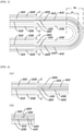
- FIG. 1A is an external view illustrating a bending part of a transmission line having improved bending durability that is unfolded according to the present disclosure.
- FIG. 1B is an external view illustrating the bending part of the transmission line having improved bending durability that is folded according to the present disclosure.
- FIG. 2A is a cross-sectional view illustrating the transmission line having improved bending durability in a transverse direction which is an extension direction of the transmission line according to Example 1 of the present disclosure.
- FIG. 2B is a cross-sectional view illustrating the transmission line having improved bending durability in a longitudinal direction according to Example 1 of the present disclosure.
- FIG. 3 is a cross-sectional view illustrating the bending part of the transmission line having improved bending durability that is bent in the transverse direction according to Example 1 of the present disclosure.
- FIG. 4A is a cross-sectional view illustrating the transmission line having improved bending durability in the transverse direction, which is the extension direction of the transmission line, according to Example 2 of the present disclosure.
- FIG. 4B is a cross-sectional view illustrating the transmission line having improved bending durability in the longitudinal direction according to Example 2 of the present disclosure.
- FIG. 5A is a cross-sectional view illustrating the transmission line having improved bending durability in the transverse direction, which is the extension direction of the transmission line, according to Example 3 of the present disclosure.
- FIG. 5B is a cross-sectional view illustrating the transmission line having improved bending durability in the longitudinal direction according to Example 3 of the present disclosure.
- the base parts 10 and the bending part 20 of the transmission line having improved bending durability includes the signal line 100, the first dielectric 210, and a second dielectric 220.
- the signal line 100 extends in a length direction to transmit a high frequency signal.
- the signal line 100 is formed on an upper surface or a lower surface of the first dielectric 210.
- the signal line 100 is formed on a surface located at an outer side among the upper surface and the lower surface of the first dielectric 210, during bending.
- the second dielectric 220 is formed above the first dielectric 210.
- the second dielectric 220 is coupled to the first dielectric 210 in the base part 10 and separated from the first dielectric 210 in the bending part 20.
- a radius of curvature R2 of the second dielectric 220 is greater than a radius of curvature R1 of the first dielectric 210 in the bending part 20, during bending, the second dielectric 220 is pulled to the base part 10 instead of the first dielectric 210 so that the second dielectric 220 is stressed instead of the first dielectric 210 which should be stressed by being pulled to the base part 10.
- the transmission line having improved bending durability according to the present disclosure further includes a first bonding sheet 310 and a first protective sheet 410.
- the first bonding sheet 310 is located between and couples the first dielectric 210 and the second dielectric 220 in the base part 10.
- a lower side of the first protective sheet 410 is coupled to the first dielectric 210 and an upper side thereof is separated from the second dielectric 220 so that the first dielectric 210 is separated from the second dielectric 220.
- one side of the first protective sheet 410 extends to the base part 10 and is located to overlap the first bonding sheet 310 between the first dielectric 210 and the second dielectric 220.
- the first protective sheet 410 prevents a large step difference between the base part 10 and the bending part 20, the first dielectric 210 is not sharply bent but gently bent.
- the one side of the first protective sheet 410 is coupled to the first bonding sheet 310 of the base part 10 to allow the first dielectric 210 to be gently bent so that there is an effect of preventing the first dielectric 210 from being damaged.
- the base part 10 and the bending part 20 of the transmission line having improved bending durability according to the present disclosure further include a third dielectric 230.
- the third dielectric 230 is formed below the first dielectric 210.
- the third dielectric 230 is coupled to the first dielectric 210 in the base part 10 and separated from the first dielectric 210 in the bending part 20.
- the third dielectric 230 since the third dielectric 230 is further included, when the third dielectric 230 is located at an outer side of the first dielectric 210 during bending, the third dielectric 230 receives stress of the first dielectric 210.
- the third dielectric 230 when the third dielectric 230 is located inward from the first dielectric 210 during bending, there is an effect in that the third dielectric 230 prevents the first dielectrics 210 from being damaged due to friction with a mechanical part disposed between the facing first dielectrics or due to friction between the facing first dielectrics.
- the base part 10 of the transmission line having improved bending durability according to the present disclosure further includes a second ground 520 and a third ground 530.
- the second ground 520 is formed in a shape corresponding to the second dielectric 220 and is formed on an upper surface of the second dielectric 220.
- the third ground 530 is formed in a shape corresponding to the third dielectric 230 and is formed on a lower surface of the third dielectric 230.
- the base part 10 and the bending part 20 of the transmission line having improved bending durability according to the present disclosure may further include a first ground 510.
- the first ground 510 is formed in a shape corresponding to the first dielectric 210 and is formed on a surface opposite to a surface of the first dielectric 210 on which the signal line 100 is formed.
- the transmission line having improved bending durability according to the present disclosure further includes a second bonding sheet 320 and a second protective sheet 420.
- the second bonding sheet 320 is located between and couples the first dielectric 210 and the third dielectric 230 in the base part 10.
- one side of the second protective sheet 420 is coupled to the first dielectric 210 and the other side thereof is separated from the third dielectric 230 so that the first dielectric 210 is separated from the third dielectric 230.
- the one side of the second protective sheet 420 extends to the base part 10 and is located to overlap the second bonding sheet 320 between the first dielectric 210 and the third dielectric 230.
- the second protective sheet 420 prevents a large step difference between the base part 10 and the bending part 20, the first dielectric 210 is not sharply bent but gently bent.
- a thickness of the third dielectric 230 is greater than a thickness of the second dielectric 220.
- the third dielectric 230 When the thickness of the third dielectric 230 is increased, an elastic force of the third dielectric 230 is increased and, even when the bending part 20 is more bent, the third dielectric 230 elastically supports the base part 10 with a high elastic force so that the first dielectric 210 is prevented from being pulled to the base part 10.
- the thickness of the third dielectric 230 located at the outer side during bending is formed to be large to increase the elastic force of the third dielectric 230 so that there is an effect in that stress applied to the first dielectric 210 is further minimized.
- the base part 10 and the bending part 20 of the transmission line having improved bending durability according to the present disclosure may further include a fourth dielectric 240.
- the fourth dielectric 240 is formed below the third dielectric 230.
- the fourth dielectric 240 is coupled to the third dielectric 230 in the base part 10 and separated from the third dielectric 230 in the bending part 20.
- the fourth dielectric 240 which is coupled to the third dielectric 230, is coupled to the third dielectric 230 through a third bonding sheet 330.
- the third dielectric 230 located at the outer side during bending and the fourth dielectric 240 located at a further outer side than the third dielectric 230 are further included so that there is an effect in that the elastic force of the dielectrics is increased to further minimize the stress applied to the first dielectric 210.
- the thickness of the third dielectric 230 and a thickness of the fourth dielectric 240 is formed to be smaller than the thickness of the second dielectric 220.
- a plurality of thin dielectrics are disposed so that there is an effect of being able to maintain the elastic force and reduce an overall thickness of the bending part 20.
- the elastic force is maintained by the third dielectric 230 and the fourth dielectric 240, and thus stress is not accumulated in the first dielectric 210 so that there is an effect of preventing the bending part 20 from being damaged during multiple times of bending.
- the base part 10 of the transmission line having improved bending durability according to the present disclosure further includes the second ground 520, the third ground 530, and a fourth ground 540.
- the second ground 520 is formed in a shape corresponding to the second dielectric 220 and is formed on the upper surface of the second dielectric 220.
- the third ground 530 is formed in a shape corresponding to the third dielectric 230 and is formed on the lower surface of the third dielectric 230.
- the fourth ground 540 is formed in a shape corresponding to the fourth dielectric 240 and is formed on a lower surface of the fourth dielectric 240.
- the bonding of the first to fourth dielectrics 210 to 240 without or with the first to third bonding sheets 310 to 330 disposed thereamong is achieved by indirect bonding through an adhesive material applied to the surfaces thereof or by direct bonding through curing after melting of the surfaces thereof.
Landscapes
- Details Of Aerials (AREA)
Claims (11)
- Übertragungsleitung, die eine verbesserte Biegebeständigkeit aufweist, umfassend eine Streifenstruktur oder eine Mikrostreifenstruktur, die in einen Basisabschnitt (10) und in einen Biegeabschnitt (20), der eingerichtet ist, basierend auf dem Basisabschnitt (10) gebogen und aufgefaltet zu werden, unterteilt ist,
wobei der Basisabschnitt (10) und der Biegeabschnitt (20) umfassen:eine Signalleitung (100), die eingerichtet ist, sich in einer Längsrichtung zu erstrecken, um ein Hochfrequenzsignal zu übertragen;ein erstes Dielektrikum (210), auf dessen oberer Oberfläche oder unterer Oberfläche die Signalleitung (100) ausgebildet ist;ein zweites Dielektrikum (220), das über dem ersten Dielektrikum (210) ausgebildet ist;eine erste Klebefolie (310), die in dem Basisabschnitt (10) zwischen dem ersten Dielektrikum (210) und dem zweiten Dielektrikum (220) angeordnet ist; undeine erste Schutzfolie (410), deren untere Seite mit dem ersten Dielektrikum (210) gekoppelt ist und deren obere Seite von dem zweiten Dielektrikum (220) in dem Biegeabschnitt (20) getrennt ist,wobei das erste Dielektrikum (210) von dem zweiten Dielektrikum (220) durch die erste Schutzfolie (410) in dem Biegeabschnitt getrennt ist,dadurch gekennzeichnet, dass das erste Dielektrikum (210) mit dem zweiten Dielektrikum (220) mittels der ersten Klebefolie (310) in dem Basisabschnitt (10) gekoppelt ist. - Übertragungsleitung nach Anspruch 1, dadurch gekennzeichnet, dass sich eine Seite der ersten Schutzfolie (410) zum Basisabschnitt (10) erstreckt und so angeordnet ist, dass sie die erste Klebefolie (310) zwischen dem ersten Dielektrikum (210) und dem zweiten Dielektrikum (220) überdeckt.
- Übertragungsleitung nach Anspruch 1, dadurch gekennzeichnet, dass der Basisabschnitt (10) und der Biegeabschnitt (20) ferner ein drittes Dielektrikum (230), das unterhalb des ersten Dielektrikums (210) ausgebildet ist, umfassen,
dadurch gekennzeichnet, dass das dritte Dielektrikum (230) mit dem ersten Dielektrikum (210) in dem Basisabschnitt (10) gekoppelt ist und von dem ersten Dielektrikum (210) in dem Biegeabschnitt (20) getrennt ist. - Übertragungsleitung nach Anspruch 3, ferner umfassend:eine zweite Klebefolie (320), die in dem Basisabschnitt (10) zwischen dem ersten Dielektrikum (210) und dem dritten Dielektrikum (230) angeordnet ist und diese koppelt; undeine zweite Schutzfolie (420), deren eine Seite mit dem ersten Dielektrikum (210) gekoppelt und deren andere Seite von dem dritten Dielektrikum (230) getrennt ist, um das erste Dielektrikum (210) von dem dritten Dielektrikum (230) in dem Biegeabschnitt (20) zu trennen.
- Übertragungsleitung nach Anspruch 4, dadurch gekennzeichnet, dass sich die eine Seite der zweiten Schutzfolie (420) zum Basisabschnitt (10) erstreckt und so angeordnet ist, dass sie die zweite Klebefolie (320) zwischen dem ersten Dielektrikum (210) und dem dritten Dielektrikum (230) überdeckt.
- Übertragungsleitung nach Anspruch 3, dadurch gekennzeichnet, dass eine Dicke des dritten Dielektrikums (230) größer als eine Dicke des zweiten Dielektrikums (220) ist.
- Übertragungsleitung nach Anspruch 3, dadurch gekennzeichnet, dass der Basisabschnitt (10) und der Biegeabschnitt (20) ferner ein viertes Dielektrikum (240), das unterhalb des dritten Dielektrikums (230) ausgebildet ist, umfassen,
dadurch gekennzeichnet, dass das vierte Dielektrikum (240) mit dem dritten Dielektrikum (230) in dem Basisabschnitt (10) gekoppelt ist und von dem dritten Dielektrikum (230) in dem Biegeabschnitt (20) getrennt ist. - Übertragungsleitung nach Anspruch 7, dadurch gekennzeichnet, dass eine Dicke eines jeden des dritten Dielektrikums (230) und des vierten Dielektrikums (240) kleiner als eine Dicke des zweiten Dielektrikums (220) ist.
- Übertragungsleitung nach Anspruch 3, dadurch gekennzeichnet, dass der Basisabschnitt (10) ferner Folgendes umfasst:eine zweite Masseverbindung (520), die in einer Form entsprechend dem zweiten Dielektrikum (220) ausgebildet ist und die auf einer oberen Oberfläche des zweiten Dielektrikums (220) ausgebildet ist; undeine dritte Masseverbindung (530), die in einer Form entsprechend dem dritten Dielektrikum (230) ausgebildet ist und die auf einer unteren Oberfläche des dritten Dielektrikums (230) ausgebildet ist.
- Übertragungsleitung nach Anspruch 7, dadurch gekennzeichnet, dass der Basisabschnitt (10) ferner Folgendes umfasst:eine zweite Masseverbindung (520), die in einer Form entsprechend dem zweiten Dielektrikum (220) ausgebildet ist und die auf einer oberen Oberfläche des zweiten Dielektrikums (220) ausgebildet ist;eine dritte Masseverbindung (530), die in einer Form entsprechend dem dritten Dielektrikum (230) ausgebildet ist und die auf einer unteren Oberfläche des dritten Dielektrikums (230) ausgebildet ist; undeine vierte Masseverbindung (540), die in einer Form entsprechend dem vierten Dielektrikum (240) ausgebildet ist und die auf einer unteren Oberfläche des vierten Dielektrikums (240) ausgebildet ist.
- Übertragungsleitung nach irgendeinem der vorherigen Ansprüche, dadurch gekennzeichnet, dass der Basisabschnitt (10) und der Biegeabschnitt (20) ferner eine erste Masseverbindung (510) umfassen, die in einer Form entsprechend dem ersten Dielektrikum (210) ausgebildet ist und die auf einer Oberfläche ausgebildet ist, die einer Oberfläche des ersten Dielektrikums (210) gegenüberliegt, auf der die Signalleitung (100) ausgebildet ist.
Applications Claiming Priority (2)
| Application Number | Priority Date | Filing Date | Title |
|---|---|---|---|
| KR1020180085864A KR101934676B1 (ko) | 2018-07-24 | 2018-07-24 | 벤딩 내구성이 향상된 전송선로 |
| PCT/KR2019/008885 WO2020022698A1 (ko) | 2018-07-24 | 2019-07-18 | 벤딩 내구성이 향상된 전송선로 |
Publications (3)
| Publication Number | Publication Date |
|---|---|
| EP3787103A1 EP3787103A1 (de) | 2021-03-03 |
| EP3787103A4 EP3787103A4 (de) | 2021-07-14 |
| EP3787103B1 true EP3787103B1 (de) | 2022-03-23 |
Family
ID=65022230
Family Applications (1)
| Application Number | Title | Priority Date | Filing Date |
|---|---|---|---|
| EP19841240.5A Active EP3787103B1 (de) | 2018-07-24 | 2019-07-18 | Übertragungsleitung mit verbesserter biegebeständigkeit |
Country Status (5)
| Country | Link |
|---|---|
| US (1) | US11489241B2 (de) |
| EP (1) | EP3787103B1 (de) |
| KR (1) | KR101934676B1 (de) |
| CN (1) | CN112136246B (de) |
| WO (1) | WO2020022698A1 (de) |
Families Citing this family (3)
| Publication number | Priority date | Publication date | Assignee | Title |
|---|---|---|---|---|
| KR101934676B1 (ko) * | 2018-07-24 | 2019-01-03 | 주식회사 기가레인 | 벤딩 내구성이 향상된 전송선로 |
| KR102766782B1 (ko) * | 2019-05-23 | 2025-02-13 | 주식회사 기가레인 | 벤딩 신뢰성이 개선된 연성회로기판 |
| CN218788856U (zh) * | 2020-04-24 | 2023-04-04 | 株式会社村田制作所 | 信号传输线路 |
Family Cites Families (24)
| Publication number | Priority date | Publication date | Assignee | Title |
|---|---|---|---|---|
| US6005524A (en) * | 1998-02-26 | 1999-12-21 | Ericsson Inc. | Flexible diversity antenna |
| JP2001210919A (ja) * | 1999-11-17 | 2001-08-03 | Sharp Corp | フレキシブル配線板およびそれを用いた電子機器 |
| KR20090054497A (ko) * | 2007-11-27 | 2009-06-01 | 삼성전자주식회사 | 연성 인쇄회로기판 및 그 제조 방법 |
| EP2239604A1 (de) * | 2008-02-01 | 2010-10-13 | Hitachi Chemical Company, Ltd. | Optoelektrische hybridplatte und elektronische vorrichtung |
| CN102057306A (zh) * | 2008-06-10 | 2011-05-11 | 住友电木株式会社 | 电子设备、便携电话机、挠性电缆、光波导形成体的制造方法 |
| TW201039520A (en) * | 2009-04-28 | 2010-11-01 | Adv Flexible Circuits Co Ltd | Flat signal transmission cable with bundling structure |
| JP2010278132A (ja) | 2009-05-27 | 2010-12-09 | Seiko Epson Corp | フレキシブル配線基板、フレキシブル配線基板の組付構造及び電子機器 |
| US8049578B1 (en) * | 2009-08-17 | 2011-11-01 | Ball Aerospace & Technologies Corp. | Air loaded stripline |
| WO2012036139A1 (ja) * | 2010-09-14 | 2012-03-22 | 株式会社村田製作所 | リーダライタ用アンテナモジュールおよびアンテナ装置 |
| JP5666270B2 (ja) * | 2010-11-29 | 2015-02-12 | 株式会社ヨコオ | 信号伝送媒体、高周波信号伝送媒体 |
| JP2014086655A (ja) | 2012-10-26 | 2014-05-12 | Murata Mfg Co Ltd | フレキシブル基板 |
| WO2014156422A1 (ja) * | 2013-03-26 | 2014-10-02 | 株式会社村田製作所 | 樹脂多層基板および電子機器 |
| CN103259070B (zh) * | 2013-04-12 | 2016-08-03 | 上海安费诺永亿通讯电子有限公司 | 一种降低损耗的传输线 |
| JP6285638B2 (ja) * | 2013-04-25 | 2018-02-28 | 日本メクトロン株式会社 | プリント配線板およびプリント配線板製造方法 |
| CN205790307U (zh) * | 2014-07-18 | 2016-12-07 | 株式会社村田制作所 | 高频信号传输线路 |
| US9933870B2 (en) * | 2015-03-17 | 2018-04-03 | Lg Display Co., Ltd. | Back plate member for flexible display, display apparatus including the same, and method of manufacturing the same |
| KR102497358B1 (ko) * | 2015-09-24 | 2023-02-10 | 주식회사 기가레인 | 벤딩 내구성이 개선된 연성회로기판 |
| KR102432541B1 (ko) * | 2015-09-24 | 2022-08-17 | 주식회사 기가레인 | 벤딩 내구성이 개선된 연성회로기판 및 그 제조방법 |
| CN205376529U (zh) * | 2015-12-30 | 2016-07-06 | 苹果公司 | 显示器 |
| KR102590307B1 (ko) * | 2016-08-30 | 2023-10-16 | 엘지디스플레이 주식회사 | 플렉서블 표시장치 |
| KR102739705B1 (ko) * | 2017-01-04 | 2024-12-06 | 주식회사 기가레인 | 연성회로기판 |
| KR102646618B1 (ko) * | 2017-01-11 | 2024-03-12 | 삼성디스플레이 주식회사 | 표시 장치 및 표시 장치의 제조 방법 |
| US10257921B1 (en) * | 2018-04-12 | 2019-04-09 | Google Llc | Embedded air gap transmission lines |
| KR101934676B1 (ko) * | 2018-07-24 | 2019-01-03 | 주식회사 기가레인 | 벤딩 내구성이 향상된 전송선로 |
-
2018
- 2018-07-24 KR KR1020180085864A patent/KR101934676B1/ko active Active
-
2019
- 2019-07-18 EP EP19841240.5A patent/EP3787103B1/de active Active
- 2019-07-18 WO PCT/KR2019/008885 patent/WO2020022698A1/ko not_active Ceased
- 2019-07-18 CN CN201980031913.0A patent/CN112136246B/zh active Active
- 2019-07-18 US US16/972,644 patent/US11489241B2/en active Active
Also Published As
| Publication number | Publication date |
|---|---|
| US20210242554A1 (en) | 2021-08-05 |
| KR101934676B1 (ko) | 2019-01-03 |
| CN112136246A (zh) | 2020-12-25 |
| CN112136246B (zh) | 2021-09-28 |
| EP3787103A4 (de) | 2021-07-14 |
| WO2020022698A1 (ko) | 2020-01-30 |
| EP3787103A1 (de) | 2021-03-03 |
| US11489241B2 (en) | 2022-11-01 |
Similar Documents
| Publication | Publication Date | Title |
|---|---|---|
| US11658376B2 (en) | Signal transmission line including a flexible resin laminate having interior hollow portions overlapping the signal transmission line with the hollow portions having a vent hole | |
| EP3787103B1 (de) | Übertragungsleitung mit verbesserter biegebeständigkeit | |
| US10561015B2 (en) | Flexible circuit board having enhanced bending durability and method for preparing same | |
| EP3422139B1 (de) | Laptop-computer | |
| US10624209B2 (en) | Flexible printed circuit board | |
| US10299375B2 (en) | Flexible circuit board having enhanced bending durability | |
| US10362675B2 (en) | Flexible circuit board having three-layer dielectric body and four-layer ground layer structure | |
| US20020070901A1 (en) | Antenna-integrated microwave-millimeter wave module | |
| KR20170094702A (ko) | 연성회로기판 | |
| US7324050B2 (en) | Antenna | |
| US11460891B2 (en) | Electronic device | |
| US11272611B2 (en) | Flexible circuit board with improved bending reliability and manufacturing method thereof | |
| US8416145B2 (en) | Multi-band printed antenna | |
| US12185459B2 (en) | Flexible printed circuit board having vertical section and horizontal section | |
| KR102575831B1 (ko) | 연성 회로 기판 및 이를 포함하는 무선 단말기 | |
| US7224315B2 (en) | Electronic device and antenna structure thereof | |
| US20240313421A1 (en) | Antenna device | |
| US20110114370A1 (en) | Dual-layer flexible printed circuit | |
| US11452200B2 (en) | Flexible circuit board including bending part with improved shielding properties and manufacturing method thereof | |
| TWI847367B (zh) | 天線裝置 | |
| TWI550953B (zh) | 單極天線 | |
| JP2022144503A (ja) | アンテナ装置、無線モジュールおよびアンテナ装置の製造方法 | |
| CN106033836A (zh) | 单极天线 |
Legal Events
| Date | Code | Title | Description |
|---|---|---|---|
| STAA | Information on the status of an ep patent application or granted ep patent |
Free format text: STATUS: THE INTERNATIONAL PUBLICATION HAS BEEN MADE |
|
| PUAI | Public reference made under article 153(3) epc to a published international application that has entered the european phase |
Free format text: ORIGINAL CODE: 0009012 |
|
| STAA | Information on the status of an ep patent application or granted ep patent |
Free format text: STATUS: REQUEST FOR EXAMINATION WAS MADE |
|
| 17P | Request for examination filed |
Effective date: 20201126 |
|
| AK | Designated contracting states |
Kind code of ref document: A1 Designated state(s): AL AT BE BG CH CY CZ DE DK EE ES FI FR GB GR HR HU IE IS IT LI LT LU LV MC MK MT NL NO PL PT RO RS SE SI SK SM TR |
|
| AX | Request for extension of the european patent |
Extension state: BA ME |
|
| A4 | Supplementary search report drawn up and despatched |
Effective date: 20210610 |
|
| RIC1 | Information provided on ipc code assigned before grant |
Ipc: H01P 3/08 20060101AFI20210604BHEP Ipc: H01P 3/12 20060101ALI20210604BHEP Ipc: G02F 1/1345 20060101ALI20210604BHEP Ipc: H01P 1/02 20060101ALN20210604BHEP |
|
| GRAP | Despatch of communication of intention to grant a patent |
Free format text: ORIGINAL CODE: EPIDOSNIGR1 |
|
| STAA | Information on the status of an ep patent application or granted ep patent |
Free format text: STATUS: GRANT OF PATENT IS INTENDED |
|
| RIC1 | Information provided on ipc code assigned before grant |
Ipc: H01P 1/02 20060101ALN20210909BHEP Ipc: G02F 1/1345 20060101ALI20210909BHEP Ipc: H01P 3/12 20060101ALI20210909BHEP Ipc: H01P 3/08 20060101AFI20210909BHEP |
|
| GRAJ | Information related to disapproval of communication of intention to grant by the applicant or resumption of examination proceedings by the epo deleted |
Free format text: ORIGINAL CODE: EPIDOSDIGR1 |
|
| GRAP | Despatch of communication of intention to grant a patent |
Free format text: ORIGINAL CODE: EPIDOSNIGR1 |
|
| DAV | Request for validation of the european patent (deleted) | ||
| DAX | Request for extension of the european patent (deleted) | ||
| INTG | Intention to grant announced |
Effective date: 20211013 |
|
| INTG | Intention to grant announced |
Effective date: 20211028 |
|
| GRAS | Grant fee paid |
Free format text: ORIGINAL CODE: EPIDOSNIGR3 |
|
| GRAA | (expected) grant |
Free format text: ORIGINAL CODE: 0009210 |
|
| STAA | Information on the status of an ep patent application or granted ep patent |
Free format text: STATUS: THE PATENT HAS BEEN GRANTED |
|
| AK | Designated contracting states |
Kind code of ref document: B1 Designated state(s): AL AT BE BG CH CY CZ DE DK EE ES FI FR GB GR HR HU IE IS IT LI LT LU LV MC MK MT NL NO PL PT RO RS SE SI SK SM TR |
|
| REG | Reference to a national code |
Ref country code: GB Ref legal event code: FG4D |
|
| REG | Reference to a national code |
Ref country code: CH Ref legal event code: EP |
|
| REG | Reference to a national code |
Ref country code: DE Ref legal event code: R096 Ref document number: 602019012897 Country of ref document: DE |
|
| REG | Reference to a national code |
Ref country code: IE Ref legal event code: FG4D |
|
| REG | Reference to a national code |
Ref country code: AT Ref legal event code: REF Ref document number: 1478082 Country of ref document: AT Kind code of ref document: T Effective date: 20220415 |
|
| REG | Reference to a national code |
Ref country code: LT Ref legal event code: MG9D |
|
| REG | Reference to a national code |
Ref country code: NL Ref legal event code: MP Effective date: 20220323 |
|
| PG25 | Lapsed in a contracting state [announced via postgrant information from national office to epo] |
Ref country code: SE Free format text: LAPSE BECAUSE OF FAILURE TO SUBMIT A TRANSLATION OF THE DESCRIPTION OR TO PAY THE FEE WITHIN THE PRESCRIBED TIME-LIMIT Effective date: 20220323 Ref country code: RS Free format text: LAPSE BECAUSE OF FAILURE TO SUBMIT A TRANSLATION OF THE DESCRIPTION OR TO PAY THE FEE WITHIN THE PRESCRIBED TIME-LIMIT Effective date: 20220323 Ref country code: NO Free format text: LAPSE BECAUSE OF FAILURE TO SUBMIT A TRANSLATION OF THE DESCRIPTION OR TO PAY THE FEE WITHIN THE PRESCRIBED TIME-LIMIT Effective date: 20220623 Ref country code: LT Free format text: LAPSE BECAUSE OF FAILURE TO SUBMIT A TRANSLATION OF THE DESCRIPTION OR TO PAY THE FEE WITHIN THE PRESCRIBED TIME-LIMIT Effective date: 20220323 Ref country code: HR Free format text: LAPSE BECAUSE OF FAILURE TO SUBMIT A TRANSLATION OF THE DESCRIPTION OR TO PAY THE FEE WITHIN THE PRESCRIBED TIME-LIMIT Effective date: 20220323 Ref country code: BG Free format text: LAPSE BECAUSE OF FAILURE TO SUBMIT A TRANSLATION OF THE DESCRIPTION OR TO PAY THE FEE WITHIN THE PRESCRIBED TIME-LIMIT Effective date: 20220623 |
|
| REG | Reference to a national code |
Ref country code: AT Ref legal event code: MK05 Ref document number: 1478082 Country of ref document: AT Kind code of ref document: T Effective date: 20220323 |
|
| PG25 | Lapsed in a contracting state [announced via postgrant information from national office to epo] |
Ref country code: LV Free format text: LAPSE BECAUSE OF FAILURE TO SUBMIT A TRANSLATION OF THE DESCRIPTION OR TO PAY THE FEE WITHIN THE PRESCRIBED TIME-LIMIT Effective date: 20220323 Ref country code: GR Free format text: LAPSE BECAUSE OF FAILURE TO SUBMIT A TRANSLATION OF THE DESCRIPTION OR TO PAY THE FEE WITHIN THE PRESCRIBED TIME-LIMIT Effective date: 20220624 Ref country code: FI Free format text: LAPSE BECAUSE OF FAILURE TO SUBMIT A TRANSLATION OF THE DESCRIPTION OR TO PAY THE FEE WITHIN THE PRESCRIBED TIME-LIMIT Effective date: 20220323 |
|
| PG25 | Lapsed in a contracting state [announced via postgrant information from national office to epo] |
Ref country code: NL Free format text: LAPSE BECAUSE OF FAILURE TO SUBMIT A TRANSLATION OF THE DESCRIPTION OR TO PAY THE FEE WITHIN THE PRESCRIBED TIME-LIMIT Effective date: 20220323 |
|
| PG25 | Lapsed in a contracting state [announced via postgrant information from national office to epo] |
Ref country code: SM Free format text: LAPSE BECAUSE OF FAILURE TO SUBMIT A TRANSLATION OF THE DESCRIPTION OR TO PAY THE FEE WITHIN THE PRESCRIBED TIME-LIMIT Effective date: 20220323 Ref country code: SK Free format text: LAPSE BECAUSE OF FAILURE TO SUBMIT A TRANSLATION OF THE DESCRIPTION OR TO PAY THE FEE WITHIN THE PRESCRIBED TIME-LIMIT Effective date: 20220323 Ref country code: RO Free format text: LAPSE BECAUSE OF FAILURE TO SUBMIT A TRANSLATION OF THE DESCRIPTION OR TO PAY THE FEE WITHIN THE PRESCRIBED TIME-LIMIT Effective date: 20220323 Ref country code: PT Free format text: LAPSE BECAUSE OF FAILURE TO SUBMIT A TRANSLATION OF THE DESCRIPTION OR TO PAY THE FEE WITHIN THE PRESCRIBED TIME-LIMIT Effective date: 20220725 Ref country code: ES Free format text: LAPSE BECAUSE OF FAILURE TO SUBMIT A TRANSLATION OF THE DESCRIPTION OR TO PAY THE FEE WITHIN THE PRESCRIBED TIME-LIMIT Effective date: 20220323 Ref country code: EE Free format text: LAPSE BECAUSE OF FAILURE TO SUBMIT A TRANSLATION OF THE DESCRIPTION OR TO PAY THE FEE WITHIN THE PRESCRIBED TIME-LIMIT Effective date: 20220323 Ref country code: CZ Free format text: LAPSE BECAUSE OF FAILURE TO SUBMIT A TRANSLATION OF THE DESCRIPTION OR TO PAY THE FEE WITHIN THE PRESCRIBED TIME-LIMIT Effective date: 20220323 Ref country code: AT Free format text: LAPSE BECAUSE OF FAILURE TO SUBMIT A TRANSLATION OF THE DESCRIPTION OR TO PAY THE FEE WITHIN THE PRESCRIBED TIME-LIMIT Effective date: 20220323 |
|
| PG25 | Lapsed in a contracting state [announced via postgrant information from national office to epo] |
Ref country code: PL Free format text: LAPSE BECAUSE OF FAILURE TO SUBMIT A TRANSLATION OF THE DESCRIPTION OR TO PAY THE FEE WITHIN THE PRESCRIBED TIME-LIMIT Effective date: 20220323 Ref country code: IS Free format text: LAPSE BECAUSE OF FAILURE TO SUBMIT A TRANSLATION OF THE DESCRIPTION OR TO PAY THE FEE WITHIN THE PRESCRIBED TIME-LIMIT Effective date: 20220723 Ref country code: AL Free format text: LAPSE BECAUSE OF FAILURE TO SUBMIT A TRANSLATION OF THE DESCRIPTION OR TO PAY THE FEE WITHIN THE PRESCRIBED TIME-LIMIT Effective date: 20220323 |
|
| REG | Reference to a national code |
Ref country code: DE Ref legal event code: R097 Ref document number: 602019012897 Country of ref document: DE |
|
| PLBE | No opposition filed within time limit |
Free format text: ORIGINAL CODE: 0009261 |
|
| STAA | Information on the status of an ep patent application or granted ep patent |
Free format text: STATUS: NO OPPOSITION FILED WITHIN TIME LIMIT |
|
| PG25 | Lapsed in a contracting state [announced via postgrant information from national office to epo] |
Ref country code: DK Free format text: LAPSE BECAUSE OF FAILURE TO SUBMIT A TRANSLATION OF THE DESCRIPTION OR TO PAY THE FEE WITHIN THE PRESCRIBED TIME-LIMIT Effective date: 20220323 |
|
| PG25 | Lapsed in a contracting state [announced via postgrant information from national office to epo] |
Ref country code: MC Free format text: LAPSE BECAUSE OF FAILURE TO SUBMIT A TRANSLATION OF THE DESCRIPTION OR TO PAY THE FEE WITHIN THE PRESCRIBED TIME-LIMIT Effective date: 20220323 |
|
| REG | Reference to a national code |
Ref country code: CH Ref legal event code: PL |
|
| 26N | No opposition filed |
Effective date: 20230102 |
|
| REG | Reference to a national code |
Ref country code: BE Ref legal event code: MM Effective date: 20220731 |
|
| PG25 | Lapsed in a contracting state [announced via postgrant information from national office to epo] |
Ref country code: LU Free format text: LAPSE BECAUSE OF NON-PAYMENT OF DUE FEES Effective date: 20220718 Ref country code: LI Free format text: LAPSE BECAUSE OF NON-PAYMENT OF DUE FEES Effective date: 20220731 Ref country code: CH Free format text: LAPSE BECAUSE OF NON-PAYMENT OF DUE FEES Effective date: 20220731 |
|
| PG25 | Lapsed in a contracting state [announced via postgrant information from national office to epo] |
Ref country code: SI Free format text: LAPSE BECAUSE OF FAILURE TO SUBMIT A TRANSLATION OF THE DESCRIPTION OR TO PAY THE FEE WITHIN THE PRESCRIBED TIME-LIMIT Effective date: 20220323 Ref country code: BE Free format text: LAPSE BECAUSE OF NON-PAYMENT OF DUE FEES Effective date: 20220731 |
|
| PG25 | Lapsed in a contracting state [announced via postgrant information from national office to epo] |
Ref country code: IT Free format text: LAPSE BECAUSE OF FAILURE TO SUBMIT A TRANSLATION OF THE DESCRIPTION OR TO PAY THE FEE WITHIN THE PRESCRIBED TIME-LIMIT Effective date: 20220323 Ref country code: IE Free format text: LAPSE BECAUSE OF NON-PAYMENT OF DUE FEES Effective date: 20220718 |
|
| PG25 | Lapsed in a contracting state [announced via postgrant information from national office to epo] |
Ref country code: MK Free format text: LAPSE BECAUSE OF FAILURE TO SUBMIT A TRANSLATION OF THE DESCRIPTION OR TO PAY THE FEE WITHIN THE PRESCRIBED TIME-LIMIT Effective date: 20220323 Ref country code: CY Free format text: LAPSE BECAUSE OF FAILURE TO SUBMIT A TRANSLATION OF THE DESCRIPTION OR TO PAY THE FEE WITHIN THE PRESCRIBED TIME-LIMIT Effective date: 20220323 |
|
| PG25 | Lapsed in a contracting state [announced via postgrant information from national office to epo] |
Ref country code: HU Free format text: LAPSE BECAUSE OF FAILURE TO SUBMIT A TRANSLATION OF THE DESCRIPTION OR TO PAY THE FEE WITHIN THE PRESCRIBED TIME-LIMIT; INVALID AB INITIO Effective date: 20190718 |
|
| PG25 | Lapsed in a contracting state [announced via postgrant information from national office to epo] |
Ref country code: MT Free format text: LAPSE BECAUSE OF FAILURE TO SUBMIT A TRANSLATION OF THE DESCRIPTION OR TO PAY THE FEE WITHIN THE PRESCRIBED TIME-LIMIT Effective date: 20220323 |
|
| PGFP | Annual fee paid to national office [announced via postgrant information from national office to epo] |
Ref country code: GB Payment date: 20250529 Year of fee payment: 7 |
|
| PGFP | Annual fee paid to national office [announced via postgrant information from national office to epo] |
Ref country code: FR Payment date: 20250610 Year of fee payment: 7 |
|
| PGFP | Annual fee paid to national office [announced via postgrant information from national office to epo] |
Ref country code: DE Payment date: 20250604 Year of fee payment: 7 |
|
| PG25 | Lapsed in a contracting state [announced via postgrant information from national office to epo] |
Ref country code: TR Free format text: LAPSE BECAUSE OF FAILURE TO SUBMIT A TRANSLATION OF THE DESCRIPTION OR TO PAY THE FEE WITHIN THE PRESCRIBED TIME-LIMIT Effective date: 20220323 |