EP3785983A1 - Rail de plancher pour un véhicule, dispositif de montage et véhicule - Google Patents
Rail de plancher pour un véhicule, dispositif de montage et véhicule Download PDFInfo
- Publication number
- EP3785983A1 EP3785983A1 EP20192804.1A EP20192804A EP3785983A1 EP 3785983 A1 EP3785983 A1 EP 3785983A1 EP 20192804 A EP20192804 A EP 20192804A EP 3785983 A1 EP3785983 A1 EP 3785983A1
- Authority
- EP
- European Patent Office
- Prior art keywords
- rail
- floor
- inner rail
- wall
- recesses
- Prior art date
- Legal status (The legal status is an assumption and is not a legal conclusion. Google has not performed a legal analysis and makes no representation as to the accuracy of the status listed.)
- Granted
Links
- 239000000463 material Substances 0.000 claims abstract description 48
- 229910052751 metal Inorganic materials 0.000 claims description 8
- 239000002184 metal Substances 0.000 claims description 8
- 229910000831 Steel Inorganic materials 0.000 claims description 7
- 229910052782 aluminium Inorganic materials 0.000 claims description 7
- XAGFODPZIPBFFR-UHFFFAOYSA-N aluminium Chemical compound [Al] XAGFODPZIPBFFR-UHFFFAOYSA-N 0.000 claims description 7
- 239000010959 steel Substances 0.000 claims description 7
- 239000007769 metal material Substances 0.000 claims description 4
- 238000004519 manufacturing process Methods 0.000 description 7
- 239000010935 stainless steel Substances 0.000 description 4
- 229910001220 stainless steel Inorganic materials 0.000 description 4
- 238000009434 installation Methods 0.000 description 3
- 230000004048 modification Effects 0.000 description 3
- 238000012986 modification Methods 0.000 description 3
- 238000007654 immersion Methods 0.000 description 2
- 238000000034 method Methods 0.000 description 2
- 239000000203 mixture Substances 0.000 description 2
- 238000012545 processing Methods 0.000 description 2
- 229910000838 Al alloy Inorganic materials 0.000 description 1
- 238000005452 bending Methods 0.000 description 1
- 239000002131 composite material Substances 0.000 description 1
- 238000010276 construction Methods 0.000 description 1
- 238000005260 corrosion Methods 0.000 description 1
- 230000007797 corrosion Effects 0.000 description 1
- 238000005520 cutting process Methods 0.000 description 1
- 230000001419 dependent effect Effects 0.000 description 1
- 230000000694 effects Effects 0.000 description 1
- 238000003754 machining Methods 0.000 description 1
- 150000002739 metals Chemical class 0.000 description 1
- 238000004080 punching Methods 0.000 description 1
- 238000007493 shaping process Methods 0.000 description 1
Images

Classifications
-
- B—PERFORMING OPERATIONS; TRANSPORTING
- B60—VEHICLES IN GENERAL
- B60N—SEATS SPECIALLY ADAPTED FOR VEHICLES; VEHICLE PASSENGER ACCOMMODATION NOT OTHERWISE PROVIDED FOR
- B60N2/00—Seats specially adapted for vehicles; Arrangement or mounting of seats in vehicles
- B60N2/02—Seats specially adapted for vehicles; Arrangement or mounting of seats in vehicles the seat or part thereof being movable, e.g. adjustable
- B60N2/04—Seats specially adapted for vehicles; Arrangement or mounting of seats in vehicles the seat or part thereof being movable, e.g. adjustable the whole seat being movable
- B60N2/06—Seats specially adapted for vehicles; Arrangement or mounting of seats in vehicles the seat or part thereof being movable, e.g. adjustable the whole seat being movable slidable
- B60N2/07—Slide construction
- B60N2/0702—Slide construction characterised by its cross-section
- B60N2/0715—C or U-shaped
-
- B—PERFORMING OPERATIONS; TRANSPORTING
- B60—VEHICLES IN GENERAL
- B60N—SEATS SPECIALLY ADAPTED FOR VEHICLES; VEHICLE PASSENGER ACCOMMODATION NOT OTHERWISE PROVIDED FOR
- B60N2/00—Seats specially adapted for vehicles; Arrangement or mounting of seats in vehicles
- B60N2/02—Seats specially adapted for vehicles; Arrangement or mounting of seats in vehicles the seat or part thereof being movable, e.g. adjustable
- B60N2/04—Seats specially adapted for vehicles; Arrangement or mounting of seats in vehicles the seat or part thereof being movable, e.g. adjustable the whole seat being movable
- B60N2/06—Seats specially adapted for vehicles; Arrangement or mounting of seats in vehicles the seat or part thereof being movable, e.g. adjustable the whole seat being movable slidable
- B60N2/07—Slide construction
- B60N2/0722—Constructive details
- B60N2/073—Reinforcement members preventing slide dislocation
-
- B—PERFORMING OPERATIONS; TRANSPORTING
- B60—VEHICLES IN GENERAL
- B60N—SEATS SPECIALLY ADAPTED FOR VEHICLES; VEHICLE PASSENGER ACCOMMODATION NOT OTHERWISE PROVIDED FOR
- B60N2/00—Seats specially adapted for vehicles; Arrangement or mounting of seats in vehicles
- B60N2/02—Seats specially adapted for vehicles; Arrangement or mounting of seats in vehicles the seat or part thereof being movable, e.g. adjustable
- B60N2/04—Seats specially adapted for vehicles; Arrangement or mounting of seats in vehicles the seat or part thereof being movable, e.g. adjustable the whole seat being movable
- B60N2/06—Seats specially adapted for vehicles; Arrangement or mounting of seats in vehicles the seat or part thereof being movable, e.g. adjustable the whole seat being movable slidable
- B60N2/07—Slide construction
- B60N2/075—Slide construction roller-less
Definitions
- a rail arrangement with preferably a plurality of floor rails is provided in the vehicle, which is present integrally on a vehicle floor or can be installed subsequently.
- the internals can be attached to the vehicle floor rail, preferably adaptable in their installation position along the floor rail and releasably fixed thereon.
- the object of the present invention is to advantageously provide a floor rail of the type mentioned at the beginning with regard to economic and technical aspects and with regard to the installation of built-in components in a vehicle.
- the invention is based on a floor rail for a vehicle, in particular a vehicle floor rail.
- the floor rail is designed for the attachment of a vehicle interior and / or a seat arrangement or other built-in components in a vehicle such as a car, a camping vehicle or a van, the floor rail being hollow and having a top side with a longitudinal slot.
- a plurality of preferably identical floor rails present in parallel in the vehicle z. B. provided for accommodating a seat arrangement.
- the floor rails preferably run parallel to the longitudinal axis of the vehicle in their longitudinal extension.
- the floor rails can be formed integrally on the vehicle floor or subsequently installed thereon, for example screwed or welded on. The connection of the interior or z. B.
- the vehicle seat arrangement such as a single vehicle seat or a two or three-seater vehicle bench is usually carried out on at least two parallel floor rails.
- the floor rail is preferably of compact construction and has a height and width in the centimeter range, with a length in the meter range, depending on the length of the interior space to be equipped in the vehicle.
- the longitudinal slot of the floor rail is preferably formed continuously over the length of the floor rail.
- the floor rail has, over its longitudinal extent, an outer rail designed as a hollow profile with opposite longitudinal rail walls extending in the longitudinal direction of the floor rail and a rail base, the rail base being opposite the upper side of the floor rail and connecting the longitudinal rail walls to one another, and wherein an inner rail is provided which is received within the hollow outer rail, the outer rail being made of a first material and the inner rail being made of a second material, the inner rail comprising a plurality of recesses in an inner rail wall, one of which is connected to the Inner rail wall adjacent rail longitudinal wall of the outer rail one Outer rail recess is present, wherein the outer rail recess adjoins several of the recesses in the inner rail wall, preferably adjoins all of the recesses in the inner rail wall.
- the second material is different from the first material.
- the floor rail according to the invention has a comparatively higher strength and / or higher elasticity than a floor rail formed from exactly one material or from a uniformly formed steel material, for example.
- the outer rail advantageously absorbs comparatively high forces and / or moments in the vertical direction based on the usage state in the vehicle and the inner rail advantageously absorbs comparatively high forces and / or moments in the horizontal direction.
- the bottom rail can be optimally coordinated with regard to the shaping and processing on the one hand and the loading capacity or mechanical stability on the other hand.
- the bottom rail is preferably constructed as a two-component component with an outer housing made of the first material or material and an interior, for example an inlay made of the second material.
- the outer rail preferably makes up the majority of the bottom rail, for example two thirds.
- the first material is preferably harder than the second material.
- the second material is preferably lighter than the first material or the second material has a lower density than the first material.
- the outer rail forms in particular the outer shape or the outer side of the floor rail.
- the floor rail is also preferably designed for attachment to a vehicle floor, for example provided with screw openings.
- the longitudinal slot of the bottom rail is accordingly formed in particular by a longitudinal slot in the outer rail that is preferably continuous over the length or not interrupted between the two ends of the rail.
- the inner rail is preferably completely accommodated in a rail cavity formed by the outer rail, for example pushed in at the end of the outer rail.
- the length of the outer rail and the length of the inner rail are at least essentially the same.
- the outer side of the inner rail adjoins the rail base and at least one rail longitudinal wall when the inner rail is L-shaped.
- the inner rail is preferably U-shaped and, with its opposing free legs, adjoins the inside of both rail longitudinal walls of the outer rail.
- the inner rail preferably has an inner rail base and an inner rail wall, the inner rail base and the inner rail wall being aligned at an angle to one another.
- the bottom rail is designed as a composite or hybrid rail or as a hybrid material rail made of a mix of materials, the outer rail being made uniformly from the first material and the inner rail being made uniformly from the second material.
- the outer rail comprises the longitudinal slot on the top, this being above an open-topped side of the z.
- U-shaped inner rail is present. This provides a hollow volume of the floor rail that is accessible from above and has an undercut area viewed from above.
- the material of the outer rail is preferably lighter than the comparatively harder material of the inner rail, which in terms of wear and a maximum load capacity of the bottom rail in a load such as an accident or crash scenario of the vehicle with z.
- B. a vehicle seat fixed on floor rails according to the invention is advantageous.
- the outer rail comprises the top of the bottom rail with a support section delimiting the longitudinal slot.
- the support section is preferably present over the entire length of the outer rail on both sides of the longitudinal slot.
- the invention is further based on the assumption that the floor rail has, over its longitudinal extent, an outer rail designed as a hollow profile with opposite longitudinal rail walls extending in the longitudinal direction of the floor rail and a rail base, the rail base being opposite the upper side of the floor rail and connecting the longitudinal rail walls to one another, and wherein an inner rail is provided, which is received within the hollow outer rail, wherein the outer rail consists of a first material and wherein the inner rail consists of a second material, wherein the inner rail in the inner rail base comprises a plurality of recesses, which are in the longitudinal direction of the inner rail from each other spaced apart, wherein a rail floor recess is present in a rail floor of the outer rail, the rail floor recess adjoining all of the recesses in the inner rail floor.
- the rail floor recess in the outer rail can be formed by several separate recesses or as a continuous groove or as a continuous channel.
- outer rail and the inner rail are firmly connected to one another.
- the two rails are detachably or permanently connected to one another, in particular after they have been joined, for. B. riveted, welded, screwed and / or clamped.
- This provides a floor rail that can withstand high mechanical loads.
- the bottom rail is comparatively highly stable, particularly in the longitudinal direction of the bottom rail and transversely thereto, or can be subjected to tension and / or pressure.
- the outer rail is advantageously formed from a light metal material such as an aluminum material.
- the outer rail material or the first material has a density preferably below 5.0 g / cm 3 .
- the outer rail preferably consists of an aluminum material or an aluminum alloy.
- the outer rail is an extruded profile.
- the production of the outer rail is thus possible in a simple and economical manner, preferably from an economically and technically easily fusible metal material such as an aluminum material.
- the inner rail is formed from a steel material.
- An inner rail made of steel preferably made of a high-grade steel material or high-grade steel sheet material, is corrosion-resistant, stable and economically advantageous to manufacture and transformable by common forming processes.
- a stainless steel material preferably has a hardness that is comparatively high to that of other metals or to a light metal and is therefore advantageous with regard to wear and tear.
- an alternative advantageous embodiment of the invention is characterized in that the inner rail is a sheet metal edge profile is trained. Production with a bending or other forming process from a standard sheet metal material that can be provided in a large number of types is thus advantageously possible.
- the inner rail is exact and with high dimensional accuracy, for. B. formed from a laser and / or stamped sheet metal component. This is also comparatively inexpensive to produce.
- the inner rail has an inner rail base and an inner rail wall, the inner rail base and the inner rail wall being aligned at an angle to one another.
- the production of the inner rail from a flat, one-piece blank such as a sheet metal to form an edge or bent part with sections oriented at an angle to one another is advantageously possible.
- the wall angled to the floor With the wall angled to the floor, a high degree of rigidity and torsional stability of the inner rail and thus the floor rail is made possible.
- the inner rail is U-shaped in cross section with an inner rail base and an inner rail wall on both sides of the inner rail base running in the longitudinal direction.
- the outer shape of the inner rail is preferably matched to an inner shape, the inner shape surrounding the hollow inner volume of the outer rail.
- the inner rail thus lines a preferably predominant area of the inner surface of the outer rail.
- the inner rail forms an internal hard surface protection of the outer rail.
- the inner rail can be produced with a comparatively small amount of material.
- the inner rail is suitable for being connected to the inner sides of the hollow U-shaped outer rail in a flush manner, which enables a compact and mechanically highly stable two-component structure.
- the inner rail and / or the outer rail has a latching contour for fixing a latching component such as a slide that can be attached to the bottom rail.
- the latching contour and the latching component are preferably part of a mounting and / or locking arrangement.
- the slide is used to attach an installation arrangement such as a seat arrangement in a vehicle to the floor rail present in the vehicle.
- the slide and the bottom rail are preferably coordinated so that the bottom rail and the slide connectable to a mounting device, the z. B. can be connected to a substructure of a vehicle seat arrangement, can be releasably latched via a locking arrangement along the floor rail in different longitudinal positions of the floor rail.
- the latching contour is used for engaging latching of a locking element of the locking arrangement. The locking is releasable but secured.
- the slide is along the bottom rail or on the top side thereof, the slide being supported on the bottom side on the top side or the bottom rail, on the bottom rail preferably via the bottom rail complete length or in the longitudinal direction can be moved back and forth along the bottom rail. Due to the continuous longitudinal slot, a section of the non-latched slide can engage in the material-free area of the longitudinal slot or between the webs.
- the slide that matches the floor rail can be supported by an attachment device, for example.
- the carriage is, for example, part of the attachment device for a seat arrangement in a vehicle, wherein the floor rail can be part of the device.
- the slide can be releasably fixed or latched on the floor rail with the aid of the locking element of the locking arrangement.
- the inner rail advantageously comprises a plurality of recesses in at least one inner rail wall, which are present at a distance from one another in the longitudinal direction of the inner rail.
- a locking element of the locking arrangement that matches a recess can interact with the recesses, which are preferably identical to one another, in order to releasably fix the slide on the floor rail.
- the locking element can adjustably either engage in a recess, which means the locked state of the slide on the floor rail, or be moved out of the recess, then the slide is not locked on the floor rail. In the unlocked state of the slide, the slide can be moved along the bottom rail or lifted upwards from the bottom rail.
- the recesses are preferably continuous through the material of the inner rail wall, that is to say they form a material-free hole.
- the recesses are, for example, polygonal or window-like.
- the recesses are preferably regularly spaced and similar or exactly opposite to one another in an inner rail wall, preferably corresponding recesses are present in both opposite inner rail walls.
- the recesses are preferably made of, for. B. a thin, for example, stainless steel or sheet steel section of the inner rail wall worked out by a cutting, punching and / or machining process.
- the inner rail in the inner rail base comprises a plurality of recesses which are present at a distance from one another in the longitudinal direction of the inner rail. In this way, the locking effect in the bottom rail can take place alone or in addition to a locking on the inner rail wall in the area of the inner rail bottom.
- the inner rail advantageously comprises a plurality of recesses in an inner rail wall, an outer rail recess being present in a longitudinal wall of the outer rail adjoining the inner rail wall, which is connected to a recess in the inner rail wall.
- the additional recess in the outer rail provides more space for reaching through and / or a greater depth for hooking a locking element onto the bottom rail.
- the immersion depth for the locking element then results from the depth of the recess in the inner rail plus the depth of the subsequent depth of the outer rail recess lying behind it.
- Each recess of the inner rail is preferably assigned an associated recess in the outer rail or the recesses are always present in adjacent pairs. In the locked state of the slide, the engaging locking element engages from the inside into the associated enlarged recess on the inner and outer rails.
- a continuous, e.g., channel-shaped recess can advantageously be provided with the production of the outer rail as an extruded profile compared to recessed window-like open recesses in the outer rail made of aluminum, since these have to be milled or drilled in an aluminum material in a time-consuming or costly manner.
- the total for The depth of immersion available for the locking element is advantageously composed of the depth of a respective recess in the inner rail and the depth of the outer rail recess, the depth of the outer rail recess generally being greater than the depth of the inner rail recess, which is the wall thickness or corresponds to the thickness of the inner rail.
- the outer rail recess is preferably present as a continuous recess, for example in the form of a channel or groove, in the outer rail or in the two rail longitudinal walls.
- the outer rail recess or the depression is accordingly preferably not a slot or gap in the outer rail, a residual base thickness preferably remains, but is preferably a channel-like depression, for example an elongated, continuous depression on the inside.
- the width of the recess preferably corresponds to the width of the respective recesses.
- the inner rail comprises a first inner rail wall with several recesses and a second opposing inner rail wall with several recesses, a first outer rail recess being present in a first longitudinal wall wall of the outer rail adjoining the first inner rail wall wherein the first outer rail recess adjoins all of the recesses in the first inner rail wall, and wherein a second outer rail recess is present in a second longitudinal rail wall of the outer rail adjoining the second inner rail wall is, wherein the second outer rail recess adjoins all of the recesses in the second inner rail wall.
- the outer rail recesses are preferably continuously z. B. channel or channel-shaped. Preferably, no recesses are then provided in the inner rail base and in the rail base of the outer rail.
- the invention also extends to a device for attaching a vehicle interior and / or a seat arrangement in a vehicle, the device having a slide that can be connected to the seat arrangement and a floor rail according to one of the preceding embodiments.
- a locking arrangement of the attachment device comprises recesses which are spaced apart from one another in the longitudinal direction of the bottom rail, and a locking element of the locking arrangement has a locking section and a contact section such that when the carriage is fixed, the locking section is in a recess in the bottom rail immersed and the contact section comes into contact with an inside of the support section, so that in the locked state with the locking section, movement of the slide in the longitudinal direction of the floor rail is blocked and the contact section prevents the slide from lifting off the floor rail.
- the slide can be arranged on the floor rail and, in the arranged but not locked or not locked state, can be moved in the longitudinal direction of the floor rail and can be fixed at different points in the longitudinal direction of the floor rail.
- the floor rail is preferably designed as a hollow profile with opposite longitudinal rail walls extending in the longitudinal direction of the floor rail. Between the rail longitudinal walls, the outer rail has a rail cavity of the bottom rail with the inner rail.
- the bottom rail has a longitudinal slot with a support section delimiting the longitudinal slot.
- the support section has an outside on which the slide is supported in the arranged state of the slide on the floor rail, the support section having an inside opposite the outside, which adjoins the rail cavity, with a locking arrangement for fixing the slide attached to the floor rail a locking element adjustably received on the slide is provided.
- a locking section on a locking element or preferably several locking sections offset from one another, which are designed in such a way that when the carriage is fixed to the floor rail, a locking section engages in a respective recess in the associated rail longitudinal wall of the floor rail.
- a floor rail 1 according to the invention for a vehicle (not shown) is shown Fig. 1 in a section or over part of the length of the floor rail 1.
- the floor rail 1 is preferably over its entire length along the longitudinal axis L of the floor rail 1 from, for example, one meter to z. B. 2 meters uniformly formed.
- the bottom rail 1 preferably designed as a vehicle bottom rail, comprises an outer rail 2 and an inner rail 3.
- the bottom rail 1 is formed as a hybrid rail from a mix of materials or from a light metal rail as the outer rail 2 and an inner rail 3 designed as an inlay rail made of a stainless steel material.
- the outer rail 2 consists, for example, of an aluminum material and is an extruded profile.
- the inner rail 3 is here a bent part formed from sheet metal, preferably a stainless steel edge profile.
- the bottom rail 1 is hollow and has an upper side 4 formed by the outer rail 2 with a longitudinal slot 5, the longitudinal slot 5 being delimited on both sides by webs 6 and 7 of the outer rail 2.
- the webs 6, 7 form with their aligned The outer sides of the flat, flat top 4 of the bottom rail 1.
- the respective outer longitudinal sides of the webs 6 and 7 opposite the longitudinal slot 5 are convexly shaped or are designed with a radius sloping outward to the plane spanned by the top 4.
- the outer rail 2 also has opposite rail longitudinal walls 8 and 9 and a rail base 10 connecting the rail longitudinal walls 8 and 9.
- the inner rail 3 has a U-shape that is open at the top or towards the longitudinal slot 5, with an inner rail base 11 and two inner rail walls 12 and 13 protruding upwards at right angles.
- Window-like rectangular recesses 14, 15 are provided approximately halfway up in a central area of the two inner rail walls 12 and 13.
- the recesses 14 in the inner rail wall 12 and the recesses 15 in the inner rail wall 13 are identical window-like and rectangular and are exactly aligned across the longitudinal axis L of the floor rail 1.
- the recesses 15 are used in particular to latch a slide (not shown), which can be placed on the bottom rail 1 from above, of an attachment device for attaching and fixing vehicle interior equipment in a vehicle interior such as, for. B. a vehicle seat.
- a slide (not shown)
- the vehicle interior on or on a vehicle floor of the vehicle there are preferably two floor rails 1 which are aligned in parallel and are spaced apart according to a width dimension of the relevant device to be installed.
- adjustable latching or locking elements of the slide With adjustable latching or locking elements of the slide, it can be fixed at any point along the bottom rail 1 over its longitudinal extent.
- the slide is along the Floor rail 1, preferably movable, for example by means of rollers or wheels of the carriage, which roll on top of the webs 6, 7.
- the inner rail 3 is precisely matched to the hollow interior or the inner contour of the outer rail 2.
- the inner rail 3 inserted in the outer rail 2 lies flat on the outside against inner sections of the outer rail 2 or the rail longitudinal walls 8 and 9.
- the outer rail 2 and the inner rail 3 are firmly connected to one another, for example riveted, screwed, clamped, welded or, for example, only screwed together with the vehicle floor during assembly in the vehicle.
- a channel-shaped or U-shaped strip-shaped outer rail is provided in the two longitudinal rail walls 8 and 9 at the level of the recesses 14 and 15, respectively.
- Recesses 16 and 17 are provided.
- the outer rail recesses 16 and 17 are matched to the recesses 14, 15 in the inner rail 3, preferably at the same height as the recesses 14, 15.
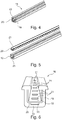
- FIGS Figures 4 to 6 Another floor rail 18 according to the invention with an outer rail 19 and an inner rail 20 are shown in FIGS Figures 4 to 6 .
- the bottom rail 18 differs from the bottom rail 1 solely in the different arrangement of recesses 21 in an inner rail bottom 22 of the inner rail 20 and an outer rail recess 23 in the outer rail 19 or in a rail bottom 24 of the outer rail 19.
Landscapes
- Engineering & Computer Science (AREA)
- Aviation & Aerospace Engineering (AREA)
- Transportation (AREA)
- Mechanical Engineering (AREA)
- Seats For Vehicles (AREA)
Priority Applications (2)
| Application Number | Priority Date | Filing Date | Title |
|---|---|---|---|
| PL20192804T PL3785983T3 (pl) | 2019-08-27 | 2020-08-26 | Szyna podłogowa do pojazdu, urządzenie mocujące i pojazd |
| SI202030064T SI3785983T1 (sl) | 2019-08-27 | 2020-08-26 | Talna tirnica za vozilo, priključno napravo in vozilo |
Applications Claiming Priority (1)
| Application Number | Priority Date | Filing Date | Title |
|---|---|---|---|
| DE102019122980.4A DE102019122980A1 (de) | 2019-08-27 | 2019-08-27 | Bodenschiene für ein Fahrzeug, Anbringvorrichtung und Fahrzeug |
Publications (2)
| Publication Number | Publication Date |
|---|---|
| EP3785983A1 true EP3785983A1 (fr) | 2021-03-03 |
| EP3785983B1 EP3785983B1 (fr) | 2022-03-30 |
Family
ID=72242979
Family Applications (1)
| Application Number | Title | Priority Date | Filing Date |
|---|---|---|---|
| EP20192804.1A Active EP3785983B1 (fr) | 2019-08-27 | 2020-08-26 | Rail de plancher pour un véhicule, dispositif de montage et véhicule |
Country Status (5)
| Country | Link |
|---|---|
| EP (1) | EP3785983B1 (fr) |
| DE (1) | DE102019122980A1 (fr) |
| ES (1) | ES2912454T3 (fr) |
| PL (1) | PL3785983T3 (fr) |
| SI (1) | SI3785983T1 (fr) |
Citations (3)
| Publication number | Priority date | Publication date | Assignee | Title |
|---|---|---|---|---|
| GB1291733A (en) * | 1969-03-20 | 1972-10-04 | Sable Feres Ets | Set of slides, more particularly for seats of agricultural tractors |
| JPH04131532U (ja) * | 1991-05-29 | 1992-12-03 | ダイハツ工業株式会社 | シートレール |
| DE4237808A1 (de) * | 1992-11-05 | 1994-05-11 | Brose Fahrzeugteile | Schienenführung mit elektrischer oder manueller Schienenverstellung |
Family Cites Families (2)
| Publication number | Priority date | Publication date | Assignee | Title |
|---|---|---|---|---|
| DE2523943A1 (de) * | 1975-05-30 | 1976-12-02 | Riehle Fa Otto | Gleitfuehrung fuer in fahrzeuglaengsrichtung verstellbare sitze |
| DE4305508A1 (de) * | 1993-02-16 | 1994-08-18 | Brose Fahrzeugteile | Schienenführung |
-
2019
- 2019-08-27 DE DE102019122980.4A patent/DE102019122980A1/de active Pending
-
2020
- 2020-08-26 PL PL20192804T patent/PL3785983T3/pl unknown
- 2020-08-26 ES ES20192804T patent/ES2912454T3/es active Active
- 2020-08-26 SI SI202030064T patent/SI3785983T1/sl unknown
- 2020-08-26 EP EP20192804.1A patent/EP3785983B1/fr active Active
Patent Citations (3)
| Publication number | Priority date | Publication date | Assignee | Title |
|---|---|---|---|---|
| GB1291733A (en) * | 1969-03-20 | 1972-10-04 | Sable Feres Ets | Set of slides, more particularly for seats of agricultural tractors |
| JPH04131532U (ja) * | 1991-05-29 | 1992-12-03 | ダイハツ工業株式会社 | シートレール |
| DE4237808A1 (de) * | 1992-11-05 | 1994-05-11 | Brose Fahrzeugteile | Schienenführung mit elektrischer oder manueller Schienenverstellung |
Also Published As
| Publication number | Publication date |
|---|---|
| SI3785983T1 (sl) | 2022-07-29 |
| EP3785983B1 (fr) | 2022-03-30 |
| ES2912454T3 (es) | 2022-05-26 |
| DE102019122980A1 (de) | 2021-03-04 |
| PL3785983T3 (pl) | 2022-05-23 |
Similar Documents
| Publication | Publication Date | Title |
|---|---|---|
| EP2608982B1 (fr) | Dispositif de réglage longitudinal d'un siège de véhicule comportant un rail inférieur et un rail supérieur séparables | |
| EP2606766B1 (fr) | Guidage d'extraction pour tiroirs coulissants avec crochet de préhension | |
| EP1479842B1 (fr) | Profilé creux | |
| DE3409582C2 (fr) | ||
| EP1839931B1 (fr) | Profil de support d'un bâti de siège sur une installation de sol d'un omnibus | |
| DE10328042A1 (de) | Gleitschiene für einen Fahrzeugsitz und Verfahren zu ihrer Herstellung | |
| EP1413472A2 (fr) | Système de glissière, notamment pour sièges de véhicules automobiles | |
| DE102013010577A1 (de) | "Korpusschiene für eine Führungseinrichtung, Führungsvorrichtung, Möbel sowie Verfahren zur Herstellung einer Korpusschiene" | |
| WO2005082557A1 (fr) | Composant profile | |
| EP3785983B1 (fr) | Rail de plancher pour un véhicule, dispositif de montage et véhicule | |
| DE19645517A1 (de) | Türblatt, insbesondere für Aufzugstüren | |
| DE1400248A1 (de) | Gleitvorrichtung fuer Sitze | |
| EP3030379B1 (fr) | Griffe de serrage pour dispositif de serrage | |
| EP2754803B1 (fr) | Crémone de fenêtre ou de porte et tringle pour une telle crémone | |
| EP1873340B1 (fr) | Installation de porte | |
| DE2923903A1 (de) | Wandbefestigungselement fuer plattenheizkoerper | |
| EP4126732A1 (fr) | Dispositif de fixation conçu pour fixer un entraînement d'une installation d'ascenseur | |
| EP3127789A2 (fr) | Ranche pour un montage de vehicule utilitaire et systeme de securisation de charge, montage de vehicule utilitaire et vehicule utilitaire comprenant une telle ranche | |
| DE958721C (de) | Gitter, z. B. Kuehler- oder Belueftungsgitter fuer Kraftfahrzeuge | |
| EP3235984B1 (fr) | Ferrure de fenêtre, son procédé de fabrication et fenêtre correspondante | |
| EP3922510B1 (fr) | Guidage de rail, agencement de siège et véhicule | |
| DE202008015077U1 (de) | Adapter zur Befestigung von Solarmodulen, mit Adapter befestigte Solarmodule und Werkzeug zum Lösen der Befestigung | |
| EP3307653B1 (fr) | Grille destinée en particulier à être utilisée en tant que tablette pour des rayonnages à plaques ou des rayonnages pour charges lourdes | |
| EP3489451B1 (fr) | Raccordement d'un coffre de volet roulant à un cadre | |
| DE102012019853B4 (de) | Tragprofil für eine Rahmentragstruktur für ein Nutzfahrzeug |
Legal Events
| Date | Code | Title | Description |
|---|---|---|---|
| PUAI | Public reference made under article 153(3) epc to a published international application that has entered the european phase |
Free format text: ORIGINAL CODE: 0009012 |
|
| STAA | Information on the status of an ep patent application or granted ep patent |
Free format text: STATUS: THE APPLICATION HAS BEEN PUBLISHED |
|
| AK | Designated contracting states |
Kind code of ref document: A1 Designated state(s): AL AT BE BG CH CY CZ DE DK EE ES FI FR GB GR HR HU IE IS IT LI LT LU LV MC MK MT NL NO PL PT RO RS SE SI SK SM TR |
|
| AX | Request for extension of the european patent |
Extension state: BA ME |
|
| STAA | Information on the status of an ep patent application or granted ep patent |
Free format text: STATUS: REQUEST FOR EXAMINATION WAS MADE |
|
| 17P | Request for examination filed |
Effective date: 20210630 |
|
| RBV | Designated contracting states (corrected) |
Designated state(s): AL AT BE BG CH CY CZ DE DK EE ES FI FR GB GR HR HU IE IS IT LI LT LU LV MC MK MT NL NO PL PT RO RS SE SI SK SM TR |
|
| GRAP | Despatch of communication of intention to grant a patent |
Free format text: ORIGINAL CODE: EPIDOSNIGR1 |
|
| STAA | Information on the status of an ep patent application or granted ep patent |
Free format text: STATUS: GRANT OF PATENT IS INTENDED |
|
| RIC1 | Information provided on ipc code assigned before grant |
Ipc: B60N 2/075 20060101ALI20210923BHEP Ipc: B60N 2/07 20060101AFI20210923BHEP |
|
| INTG | Intention to grant announced |
Effective date: 20211019 |
|
| GRAS | Grant fee paid |
Free format text: ORIGINAL CODE: EPIDOSNIGR3 |
|
| GRAA | (expected) grant |
Free format text: ORIGINAL CODE: 0009210 |
|
| STAA | Information on the status of an ep patent application or granted ep patent |
Free format text: STATUS: THE PATENT HAS BEEN GRANTED |
|
| AK | Designated contracting states |
Kind code of ref document: B1 Designated state(s): AL AT BE BG CH CY CZ DE DK EE ES FI FR GB GR HR HU IE IS IT LI LT LU LV MC MK MT NL NO PL PT RO RS SE SI SK SM TR |
|
| REG | Reference to a national code |
Ref country code: GB Ref legal event code: FG4D Free format text: NOT ENGLISH |
|
| REG | Reference to a national code |
Ref country code: CH Ref legal event code: EP |
|
| REG | Reference to a national code |
Ref country code: AT Ref legal event code: REF Ref document number: 1478888 Country of ref document: AT Kind code of ref document: T Effective date: 20220415 |
|
| REG | Reference to a national code |
Ref country code: DE Ref legal event code: R096 Ref document number: 502020000869 Country of ref document: DE |
|
| REG | Reference to a national code |
Ref country code: IE Ref legal event code: FG4D Free format text: LANGUAGE OF EP DOCUMENT: GERMAN |
|
| REG | Reference to a national code |
Ref country code: ES Ref legal event code: FG2A Ref document number: 2912454 Country of ref document: ES Kind code of ref document: T3 Effective date: 20220526 |
|
| REG | Reference to a national code |
Ref country code: SE Ref legal event code: TRGR |
|
| REG | Reference to a national code |
Ref country code: LT Ref legal event code: MG9D |
|
| PG25 | Lapsed in a contracting state [announced via postgrant information from national office to epo] |
Ref country code: RS Free format text: LAPSE BECAUSE OF FAILURE TO SUBMIT A TRANSLATION OF THE DESCRIPTION OR TO PAY THE FEE WITHIN THE PRESCRIBED TIME-LIMIT Effective date: 20220330 Ref country code: NO Free format text: LAPSE BECAUSE OF FAILURE TO SUBMIT A TRANSLATION OF THE DESCRIPTION OR TO PAY THE FEE WITHIN THE PRESCRIBED TIME-LIMIT Effective date: 20220630 Ref country code: LT Free format text: LAPSE BECAUSE OF FAILURE TO SUBMIT A TRANSLATION OF THE DESCRIPTION OR TO PAY THE FEE WITHIN THE PRESCRIBED TIME-LIMIT Effective date: 20220330 Ref country code: HR Free format text: LAPSE BECAUSE OF FAILURE TO SUBMIT A TRANSLATION OF THE DESCRIPTION OR TO PAY THE FEE WITHIN THE PRESCRIBED TIME-LIMIT Effective date: 20220330 Ref country code: BG Free format text: LAPSE BECAUSE OF FAILURE TO SUBMIT A TRANSLATION OF THE DESCRIPTION OR TO PAY THE FEE WITHIN THE PRESCRIBED TIME-LIMIT Effective date: 20220630 |
|
| REG | Reference to a national code |
Ref country code: NL Ref legal event code: MP Effective date: 20220330 |
|
| REG | Reference to a national code |
Ref country code: HU Ref legal event code: AG4A Ref document number: E058553 Country of ref document: HU |
|
| PG25 | Lapsed in a contracting state [announced via postgrant information from national office to epo] |
Ref country code: LV Free format text: LAPSE BECAUSE OF FAILURE TO SUBMIT A TRANSLATION OF THE DESCRIPTION OR TO PAY THE FEE WITHIN THE PRESCRIBED TIME-LIMIT Effective date: 20220330 Ref country code: GR Free format text: LAPSE BECAUSE OF FAILURE TO SUBMIT A TRANSLATION OF THE DESCRIPTION OR TO PAY THE FEE WITHIN THE PRESCRIBED TIME-LIMIT Effective date: 20220701 Ref country code: FI Free format text: LAPSE BECAUSE OF FAILURE TO SUBMIT A TRANSLATION OF THE DESCRIPTION OR TO PAY THE FEE WITHIN THE PRESCRIBED TIME-LIMIT Effective date: 20220330 |
|
| PG25 | Lapsed in a contracting state [announced via postgrant information from national office to epo] |
Ref country code: NL Free format text: LAPSE BECAUSE OF FAILURE TO SUBMIT A TRANSLATION OF THE DESCRIPTION OR TO PAY THE FEE WITHIN THE PRESCRIBED TIME-LIMIT Effective date: 20220330 |
|
| PG25 | Lapsed in a contracting state [announced via postgrant information from national office to epo] |
Ref country code: SM Free format text: LAPSE BECAUSE OF FAILURE TO SUBMIT A TRANSLATION OF THE DESCRIPTION OR TO PAY THE FEE WITHIN THE PRESCRIBED TIME-LIMIT Effective date: 20220330 Ref country code: SK Free format text: LAPSE BECAUSE OF FAILURE TO SUBMIT A TRANSLATION OF THE DESCRIPTION OR TO PAY THE FEE WITHIN THE PRESCRIBED TIME-LIMIT Effective date: 20220330 Ref country code: RO Free format text: LAPSE BECAUSE OF FAILURE TO SUBMIT A TRANSLATION OF THE DESCRIPTION OR TO PAY THE FEE WITHIN THE PRESCRIBED TIME-LIMIT Effective date: 20220330 Ref country code: PT Free format text: LAPSE BECAUSE OF FAILURE TO SUBMIT A TRANSLATION OF THE DESCRIPTION OR TO PAY THE FEE WITHIN THE PRESCRIBED TIME-LIMIT Effective date: 20220801 Ref country code: EE Free format text: LAPSE BECAUSE OF FAILURE TO SUBMIT A TRANSLATION OF THE DESCRIPTION OR TO PAY THE FEE WITHIN THE PRESCRIBED TIME-LIMIT Effective date: 20220330 Ref country code: CZ Free format text: LAPSE BECAUSE OF FAILURE TO SUBMIT A TRANSLATION OF THE DESCRIPTION OR TO PAY THE FEE WITHIN THE PRESCRIBED TIME-LIMIT Effective date: 20220330 |
|
| PG25 | Lapsed in a contracting state [announced via postgrant information from national office to epo] |
Ref country code: IS Free format text: LAPSE BECAUSE OF FAILURE TO SUBMIT A TRANSLATION OF THE DESCRIPTION OR TO PAY THE FEE WITHIN THE PRESCRIBED TIME-LIMIT Effective date: 20220730 Ref country code: AL Free format text: LAPSE BECAUSE OF FAILURE TO SUBMIT A TRANSLATION OF THE DESCRIPTION OR TO PAY THE FEE WITHIN THE PRESCRIBED TIME-LIMIT Effective date: 20220330 |
|
| REG | Reference to a national code |
Ref country code: DE Ref legal event code: R097 Ref document number: 502020000869 Country of ref document: DE |
|
| PG25 | Lapsed in a contracting state [announced via postgrant information from national office to epo] |
Ref country code: DK Free format text: LAPSE BECAUSE OF FAILURE TO SUBMIT A TRANSLATION OF THE DESCRIPTION OR TO PAY THE FEE WITHIN THE PRESCRIBED TIME-LIMIT Effective date: 20220330 |
|
| PGFP | Annual fee paid to national office [announced via postgrant information from national office to epo] |
Ref country code: IE Payment date: 20221118 Year of fee payment: 3 |
|
| PLBE | No opposition filed within time limit |
Free format text: ORIGINAL CODE: 0009261 |
|
| STAA | Information on the status of an ep patent application or granted ep patent |
Free format text: STATUS: NO OPPOSITION FILED WITHIN TIME LIMIT |
|
| 26N | No opposition filed |
Effective date: 20230103 |
|
| PG25 | Lapsed in a contracting state [announced via postgrant information from national office to epo] |
Ref country code: MC Free format text: LAPSE BECAUSE OF FAILURE TO SUBMIT A TRANSLATION OF THE DESCRIPTION OR TO PAY THE FEE WITHIN THE PRESCRIBED TIME-LIMIT Effective date: 20220330 |
|
| PG25 | Lapsed in a contracting state [announced via postgrant information from national office to epo] |
Ref country code: LU Free format text: LAPSE BECAUSE OF NON-PAYMENT OF DUE FEES Effective date: 20220826 |
|
| REG | Reference to a national code |
Ref country code: BE Ref legal event code: MM Effective date: 20220831 |
|
| PG25 | Lapsed in a contracting state [announced via postgrant information from national office to epo] |
Ref country code: BE Free format text: LAPSE BECAUSE OF NON-PAYMENT OF DUE FEES Effective date: 20220831 |
|
| PGFP | Annual fee paid to national office [announced via postgrant information from national office to epo] |
Ref country code: TR Payment date: 20230817 Year of fee payment: 4 Ref country code: IT Payment date: 20230831 Year of fee payment: 4 Ref country code: ES Payment date: 20230918 Year of fee payment: 4 |
|
| PGFP | Annual fee paid to national office [announced via postgrant information from national office to epo] |
Ref country code: SI Payment date: 20230816 Year of fee payment: 4 Ref country code: SE Payment date: 20230823 Year of fee payment: 4 Ref country code: PL Payment date: 20230817 Year of fee payment: 4 Ref country code: HU Payment date: 20230817 Year of fee payment: 4 Ref country code: FR Payment date: 20230821 Year of fee payment: 4 Ref country code: DE Payment date: 20230822 Year of fee payment: 4 |
|
| REG | Reference to a national code |
Ref country code: CH Ref legal event code: PL |
|
| PG25 | Lapsed in a contracting state [announced via postgrant information from national office to epo] |
Ref country code: CY Free format text: LAPSE BECAUSE OF FAILURE TO SUBMIT A TRANSLATION OF THE DESCRIPTION OR TO PAY THE FEE WITHIN THE PRESCRIBED TIME-LIMIT Effective date: 20220330 Ref country code: CH Free format text: LAPSE BECAUSE OF NON-PAYMENT OF DUE FEES Effective date: 20230831 |
|
| REG | Reference to a national code |
Ref country code: IE Ref legal event code: MM4A |