EP3785983A1 - Floor rail for a vehicle, attachment device and vehicle - Google Patents
Floor rail for a vehicle, attachment device and vehicle Download PDFInfo
- Publication number
- EP3785983A1 EP3785983A1 EP20192804.1A EP20192804A EP3785983A1 EP 3785983 A1 EP3785983 A1 EP 3785983A1 EP 20192804 A EP20192804 A EP 20192804A EP 3785983 A1 EP3785983 A1 EP 3785983A1
- Authority
- EP
- European Patent Office
- Prior art keywords
- rail
- floor
- inner rail
- wall
- recesses
- Prior art date
- Legal status (The legal status is an assumption and is not a legal conclusion. Google has not performed a legal analysis and makes no representation as to the accuracy of the status listed.)
- Granted
Links
- 239000000463 material Substances 0.000 claims abstract description 48
- 229910052751 metal Inorganic materials 0.000 claims description 8
- 239000002184 metal Substances 0.000 claims description 8
- 229910000831 Steel Inorganic materials 0.000 claims description 7
- 229910052782 aluminium Inorganic materials 0.000 claims description 7
- XAGFODPZIPBFFR-UHFFFAOYSA-N aluminium Chemical compound [Al] XAGFODPZIPBFFR-UHFFFAOYSA-N 0.000 claims description 7
- 239000010959 steel Substances 0.000 claims description 7
- 239000007769 metal material Substances 0.000 claims description 4
- 238000004519 manufacturing process Methods 0.000 description 7
- 239000010935 stainless steel Substances 0.000 description 4
- 229910001220 stainless steel Inorganic materials 0.000 description 4
- 238000009434 installation Methods 0.000 description 3
- 230000004048 modification Effects 0.000 description 3
- 238000012986 modification Methods 0.000 description 3
- 238000007654 immersion Methods 0.000 description 2
- 238000000034 method Methods 0.000 description 2
- 239000000203 mixture Substances 0.000 description 2
- 238000012545 processing Methods 0.000 description 2
- 229910000838 Al alloy Inorganic materials 0.000 description 1
- 238000005452 bending Methods 0.000 description 1
- 239000002131 composite material Substances 0.000 description 1
- 238000010276 construction Methods 0.000 description 1
- 238000005260 corrosion Methods 0.000 description 1
- 230000007797 corrosion Effects 0.000 description 1
- 238000005520 cutting process Methods 0.000 description 1
- 230000001419 dependent effect Effects 0.000 description 1
- 230000000694 effects Effects 0.000 description 1
- 238000003754 machining Methods 0.000 description 1
- 150000002739 metals Chemical class 0.000 description 1
- 238000004080 punching Methods 0.000 description 1
- 238000007493 shaping process Methods 0.000 description 1
Images

Classifications
-
- B—PERFORMING OPERATIONS; TRANSPORTING
- B60—VEHICLES IN GENERAL
- B60N—SEATS SPECIALLY ADAPTED FOR VEHICLES; VEHICLE PASSENGER ACCOMMODATION NOT OTHERWISE PROVIDED FOR
- B60N2/00—Seats specially adapted for vehicles; Arrangement or mounting of seats in vehicles
- B60N2/02—Seats specially adapted for vehicles; Arrangement or mounting of seats in vehicles the seat or part thereof being movable, e.g. adjustable
- B60N2/04—Seats specially adapted for vehicles; Arrangement or mounting of seats in vehicles the seat or part thereof being movable, e.g. adjustable the whole seat being movable
- B60N2/06—Seats specially adapted for vehicles; Arrangement or mounting of seats in vehicles the seat or part thereof being movable, e.g. adjustable the whole seat being movable slidable
- B60N2/07—Slide construction
- B60N2/0702—Slide construction characterised by its cross-section
- B60N2/0715—C or U-shaped
-
- B—PERFORMING OPERATIONS; TRANSPORTING
- B60—VEHICLES IN GENERAL
- B60N—SEATS SPECIALLY ADAPTED FOR VEHICLES; VEHICLE PASSENGER ACCOMMODATION NOT OTHERWISE PROVIDED FOR
- B60N2/00—Seats specially adapted for vehicles; Arrangement or mounting of seats in vehicles
- B60N2/02—Seats specially adapted for vehicles; Arrangement or mounting of seats in vehicles the seat or part thereof being movable, e.g. adjustable
- B60N2/04—Seats specially adapted for vehicles; Arrangement or mounting of seats in vehicles the seat or part thereof being movable, e.g. adjustable the whole seat being movable
- B60N2/06—Seats specially adapted for vehicles; Arrangement or mounting of seats in vehicles the seat or part thereof being movable, e.g. adjustable the whole seat being movable slidable
- B60N2/07—Slide construction
- B60N2/0722—Constructive details
- B60N2/073—Reinforcement members preventing slide dislocation
-
- B—PERFORMING OPERATIONS; TRANSPORTING
- B60—VEHICLES IN GENERAL
- B60N—SEATS SPECIALLY ADAPTED FOR VEHICLES; VEHICLE PASSENGER ACCOMMODATION NOT OTHERWISE PROVIDED FOR
- B60N2/00—Seats specially adapted for vehicles; Arrangement or mounting of seats in vehicles
- B60N2/02—Seats specially adapted for vehicles; Arrangement or mounting of seats in vehicles the seat or part thereof being movable, e.g. adjustable
- B60N2/04—Seats specially adapted for vehicles; Arrangement or mounting of seats in vehicles the seat or part thereof being movable, e.g. adjustable the whole seat being movable
- B60N2/06—Seats specially adapted for vehicles; Arrangement or mounting of seats in vehicles the seat or part thereof being movable, e.g. adjustable the whole seat being movable slidable
- B60N2/07—Slide construction
- B60N2/075—Slide construction roller-less
Definitions
- a rail arrangement with preferably a plurality of floor rails is provided in the vehicle, which is present integrally on a vehicle floor or can be installed subsequently.
- the internals can be attached to the vehicle floor rail, preferably adaptable in their installation position along the floor rail and releasably fixed thereon.
- the object of the present invention is to advantageously provide a floor rail of the type mentioned at the beginning with regard to economic and technical aspects and with regard to the installation of built-in components in a vehicle.
- the invention is based on a floor rail for a vehicle, in particular a vehicle floor rail.
- the floor rail is designed for the attachment of a vehicle interior and / or a seat arrangement or other built-in components in a vehicle such as a car, a camping vehicle or a van, the floor rail being hollow and having a top side with a longitudinal slot.
- a plurality of preferably identical floor rails present in parallel in the vehicle z. B. provided for accommodating a seat arrangement.
- the floor rails preferably run parallel to the longitudinal axis of the vehicle in their longitudinal extension.
- the floor rails can be formed integrally on the vehicle floor or subsequently installed thereon, for example screwed or welded on. The connection of the interior or z. B.
- the vehicle seat arrangement such as a single vehicle seat or a two or three-seater vehicle bench is usually carried out on at least two parallel floor rails.
- the floor rail is preferably of compact construction and has a height and width in the centimeter range, with a length in the meter range, depending on the length of the interior space to be equipped in the vehicle.
- the longitudinal slot of the floor rail is preferably formed continuously over the length of the floor rail.
- the floor rail has, over its longitudinal extent, an outer rail designed as a hollow profile with opposite longitudinal rail walls extending in the longitudinal direction of the floor rail and a rail base, the rail base being opposite the upper side of the floor rail and connecting the longitudinal rail walls to one another, and wherein an inner rail is provided which is received within the hollow outer rail, the outer rail being made of a first material and the inner rail being made of a second material, the inner rail comprising a plurality of recesses in an inner rail wall, one of which is connected to the Inner rail wall adjacent rail longitudinal wall of the outer rail one Outer rail recess is present, wherein the outer rail recess adjoins several of the recesses in the inner rail wall, preferably adjoins all of the recesses in the inner rail wall.
- the second material is different from the first material.
- the floor rail according to the invention has a comparatively higher strength and / or higher elasticity than a floor rail formed from exactly one material or from a uniformly formed steel material, for example.
- the outer rail advantageously absorbs comparatively high forces and / or moments in the vertical direction based on the usage state in the vehicle and the inner rail advantageously absorbs comparatively high forces and / or moments in the horizontal direction.
- the bottom rail can be optimally coordinated with regard to the shaping and processing on the one hand and the loading capacity or mechanical stability on the other hand.
- the bottom rail is preferably constructed as a two-component component with an outer housing made of the first material or material and an interior, for example an inlay made of the second material.
- the outer rail preferably makes up the majority of the bottom rail, for example two thirds.
- the first material is preferably harder than the second material.
- the second material is preferably lighter than the first material or the second material has a lower density than the first material.
- the outer rail forms in particular the outer shape or the outer side of the floor rail.
- the floor rail is also preferably designed for attachment to a vehicle floor, for example provided with screw openings.
- the longitudinal slot of the bottom rail is accordingly formed in particular by a longitudinal slot in the outer rail that is preferably continuous over the length or not interrupted between the two ends of the rail.
- the inner rail is preferably completely accommodated in a rail cavity formed by the outer rail, for example pushed in at the end of the outer rail.
- the length of the outer rail and the length of the inner rail are at least essentially the same.
- the outer side of the inner rail adjoins the rail base and at least one rail longitudinal wall when the inner rail is L-shaped.
- the inner rail is preferably U-shaped and, with its opposing free legs, adjoins the inside of both rail longitudinal walls of the outer rail.
- the inner rail preferably has an inner rail base and an inner rail wall, the inner rail base and the inner rail wall being aligned at an angle to one another.
- the bottom rail is designed as a composite or hybrid rail or as a hybrid material rail made of a mix of materials, the outer rail being made uniformly from the first material and the inner rail being made uniformly from the second material.
- the outer rail comprises the longitudinal slot on the top, this being above an open-topped side of the z.
- U-shaped inner rail is present. This provides a hollow volume of the floor rail that is accessible from above and has an undercut area viewed from above.
- the material of the outer rail is preferably lighter than the comparatively harder material of the inner rail, which in terms of wear and a maximum load capacity of the bottom rail in a load such as an accident or crash scenario of the vehicle with z.
- B. a vehicle seat fixed on floor rails according to the invention is advantageous.
- the outer rail comprises the top of the bottom rail with a support section delimiting the longitudinal slot.
- the support section is preferably present over the entire length of the outer rail on both sides of the longitudinal slot.
- the invention is further based on the assumption that the floor rail has, over its longitudinal extent, an outer rail designed as a hollow profile with opposite longitudinal rail walls extending in the longitudinal direction of the floor rail and a rail base, the rail base being opposite the upper side of the floor rail and connecting the longitudinal rail walls to one another, and wherein an inner rail is provided, which is received within the hollow outer rail, wherein the outer rail consists of a first material and wherein the inner rail consists of a second material, wherein the inner rail in the inner rail base comprises a plurality of recesses, which are in the longitudinal direction of the inner rail from each other spaced apart, wherein a rail floor recess is present in a rail floor of the outer rail, the rail floor recess adjoining all of the recesses in the inner rail floor.
- the rail floor recess in the outer rail can be formed by several separate recesses or as a continuous groove or as a continuous channel.
- outer rail and the inner rail are firmly connected to one another.
- the two rails are detachably or permanently connected to one another, in particular after they have been joined, for. B. riveted, welded, screwed and / or clamped.
- This provides a floor rail that can withstand high mechanical loads.
- the bottom rail is comparatively highly stable, particularly in the longitudinal direction of the bottom rail and transversely thereto, or can be subjected to tension and / or pressure.
- the outer rail is advantageously formed from a light metal material such as an aluminum material.
- the outer rail material or the first material has a density preferably below 5.0 g / cm 3 .
- the outer rail preferably consists of an aluminum material or an aluminum alloy.
- the outer rail is an extruded profile.
- the production of the outer rail is thus possible in a simple and economical manner, preferably from an economically and technically easily fusible metal material such as an aluminum material.
- the inner rail is formed from a steel material.
- An inner rail made of steel preferably made of a high-grade steel material or high-grade steel sheet material, is corrosion-resistant, stable and economically advantageous to manufacture and transformable by common forming processes.
- a stainless steel material preferably has a hardness that is comparatively high to that of other metals or to a light metal and is therefore advantageous with regard to wear and tear.
- an alternative advantageous embodiment of the invention is characterized in that the inner rail is a sheet metal edge profile is trained. Production with a bending or other forming process from a standard sheet metal material that can be provided in a large number of types is thus advantageously possible.
- the inner rail is exact and with high dimensional accuracy, for. B. formed from a laser and / or stamped sheet metal component. This is also comparatively inexpensive to produce.
- the inner rail has an inner rail base and an inner rail wall, the inner rail base and the inner rail wall being aligned at an angle to one another.
- the production of the inner rail from a flat, one-piece blank such as a sheet metal to form an edge or bent part with sections oriented at an angle to one another is advantageously possible.
- the wall angled to the floor With the wall angled to the floor, a high degree of rigidity and torsional stability of the inner rail and thus the floor rail is made possible.
- the inner rail is U-shaped in cross section with an inner rail base and an inner rail wall on both sides of the inner rail base running in the longitudinal direction.
- the outer shape of the inner rail is preferably matched to an inner shape, the inner shape surrounding the hollow inner volume of the outer rail.
- the inner rail thus lines a preferably predominant area of the inner surface of the outer rail.
- the inner rail forms an internal hard surface protection of the outer rail.
- the inner rail can be produced with a comparatively small amount of material.
- the inner rail is suitable for being connected to the inner sides of the hollow U-shaped outer rail in a flush manner, which enables a compact and mechanically highly stable two-component structure.
- the inner rail and / or the outer rail has a latching contour for fixing a latching component such as a slide that can be attached to the bottom rail.
- the latching contour and the latching component are preferably part of a mounting and / or locking arrangement.
- the slide is used to attach an installation arrangement such as a seat arrangement in a vehicle to the floor rail present in the vehicle.
- the slide and the bottom rail are preferably coordinated so that the bottom rail and the slide connectable to a mounting device, the z. B. can be connected to a substructure of a vehicle seat arrangement, can be releasably latched via a locking arrangement along the floor rail in different longitudinal positions of the floor rail.
- the latching contour is used for engaging latching of a locking element of the locking arrangement. The locking is releasable but secured.
- the slide is along the bottom rail or on the top side thereof, the slide being supported on the bottom side on the top side or the bottom rail, on the bottom rail preferably via the bottom rail complete length or in the longitudinal direction can be moved back and forth along the bottom rail. Due to the continuous longitudinal slot, a section of the non-latched slide can engage in the material-free area of the longitudinal slot or between the webs.
- the slide that matches the floor rail can be supported by an attachment device, for example.
- the carriage is, for example, part of the attachment device for a seat arrangement in a vehicle, wherein the floor rail can be part of the device.
- the slide can be releasably fixed or latched on the floor rail with the aid of the locking element of the locking arrangement.
- the inner rail advantageously comprises a plurality of recesses in at least one inner rail wall, which are present at a distance from one another in the longitudinal direction of the inner rail.
- a locking element of the locking arrangement that matches a recess can interact with the recesses, which are preferably identical to one another, in order to releasably fix the slide on the floor rail.
- the locking element can adjustably either engage in a recess, which means the locked state of the slide on the floor rail, or be moved out of the recess, then the slide is not locked on the floor rail. In the unlocked state of the slide, the slide can be moved along the bottom rail or lifted upwards from the bottom rail.
- the recesses are preferably continuous through the material of the inner rail wall, that is to say they form a material-free hole.
- the recesses are, for example, polygonal or window-like.
- the recesses are preferably regularly spaced and similar or exactly opposite to one another in an inner rail wall, preferably corresponding recesses are present in both opposite inner rail walls.
- the recesses are preferably made of, for. B. a thin, for example, stainless steel or sheet steel section of the inner rail wall worked out by a cutting, punching and / or machining process.
- the inner rail in the inner rail base comprises a plurality of recesses which are present at a distance from one another in the longitudinal direction of the inner rail. In this way, the locking effect in the bottom rail can take place alone or in addition to a locking on the inner rail wall in the area of the inner rail bottom.
- the inner rail advantageously comprises a plurality of recesses in an inner rail wall, an outer rail recess being present in a longitudinal wall of the outer rail adjoining the inner rail wall, which is connected to a recess in the inner rail wall.
- the additional recess in the outer rail provides more space for reaching through and / or a greater depth for hooking a locking element onto the bottom rail.
- the immersion depth for the locking element then results from the depth of the recess in the inner rail plus the depth of the subsequent depth of the outer rail recess lying behind it.
- Each recess of the inner rail is preferably assigned an associated recess in the outer rail or the recesses are always present in adjacent pairs. In the locked state of the slide, the engaging locking element engages from the inside into the associated enlarged recess on the inner and outer rails.
- a continuous, e.g., channel-shaped recess can advantageously be provided with the production of the outer rail as an extruded profile compared to recessed window-like open recesses in the outer rail made of aluminum, since these have to be milled or drilled in an aluminum material in a time-consuming or costly manner.
- the total for The depth of immersion available for the locking element is advantageously composed of the depth of a respective recess in the inner rail and the depth of the outer rail recess, the depth of the outer rail recess generally being greater than the depth of the inner rail recess, which is the wall thickness or corresponds to the thickness of the inner rail.
- the outer rail recess is preferably present as a continuous recess, for example in the form of a channel or groove, in the outer rail or in the two rail longitudinal walls.
- the outer rail recess or the depression is accordingly preferably not a slot or gap in the outer rail, a residual base thickness preferably remains, but is preferably a channel-like depression, for example an elongated, continuous depression on the inside.
- the width of the recess preferably corresponds to the width of the respective recesses.
- the inner rail comprises a first inner rail wall with several recesses and a second opposing inner rail wall with several recesses, a first outer rail recess being present in a first longitudinal wall wall of the outer rail adjoining the first inner rail wall wherein the first outer rail recess adjoins all of the recesses in the first inner rail wall, and wherein a second outer rail recess is present in a second longitudinal rail wall of the outer rail adjoining the second inner rail wall is, wherein the second outer rail recess adjoins all of the recesses in the second inner rail wall.
- the outer rail recesses are preferably continuously z. B. channel or channel-shaped. Preferably, no recesses are then provided in the inner rail base and in the rail base of the outer rail.
- the invention also extends to a device for attaching a vehicle interior and / or a seat arrangement in a vehicle, the device having a slide that can be connected to the seat arrangement and a floor rail according to one of the preceding embodiments.
- a locking arrangement of the attachment device comprises recesses which are spaced apart from one another in the longitudinal direction of the bottom rail, and a locking element of the locking arrangement has a locking section and a contact section such that when the carriage is fixed, the locking section is in a recess in the bottom rail immersed and the contact section comes into contact with an inside of the support section, so that in the locked state with the locking section, movement of the slide in the longitudinal direction of the floor rail is blocked and the contact section prevents the slide from lifting off the floor rail.
- the slide can be arranged on the floor rail and, in the arranged but not locked or not locked state, can be moved in the longitudinal direction of the floor rail and can be fixed at different points in the longitudinal direction of the floor rail.
- the floor rail is preferably designed as a hollow profile with opposite longitudinal rail walls extending in the longitudinal direction of the floor rail. Between the rail longitudinal walls, the outer rail has a rail cavity of the bottom rail with the inner rail.
- the bottom rail has a longitudinal slot with a support section delimiting the longitudinal slot.
- the support section has an outside on which the slide is supported in the arranged state of the slide on the floor rail, the support section having an inside opposite the outside, which adjoins the rail cavity, with a locking arrangement for fixing the slide attached to the floor rail a locking element adjustably received on the slide is provided.
- a locking section on a locking element or preferably several locking sections offset from one another, which are designed in such a way that when the carriage is fixed to the floor rail, a locking section engages in a respective recess in the associated rail longitudinal wall of the floor rail.
- a floor rail 1 according to the invention for a vehicle (not shown) is shown Fig. 1 in a section or over part of the length of the floor rail 1.
- the floor rail 1 is preferably over its entire length along the longitudinal axis L of the floor rail 1 from, for example, one meter to z. B. 2 meters uniformly formed.
- the bottom rail 1 preferably designed as a vehicle bottom rail, comprises an outer rail 2 and an inner rail 3.
- the bottom rail 1 is formed as a hybrid rail from a mix of materials or from a light metal rail as the outer rail 2 and an inner rail 3 designed as an inlay rail made of a stainless steel material.
- the outer rail 2 consists, for example, of an aluminum material and is an extruded profile.
- the inner rail 3 is here a bent part formed from sheet metal, preferably a stainless steel edge profile.
- the bottom rail 1 is hollow and has an upper side 4 formed by the outer rail 2 with a longitudinal slot 5, the longitudinal slot 5 being delimited on both sides by webs 6 and 7 of the outer rail 2.
- the webs 6, 7 form with their aligned The outer sides of the flat, flat top 4 of the bottom rail 1.
- the respective outer longitudinal sides of the webs 6 and 7 opposite the longitudinal slot 5 are convexly shaped or are designed with a radius sloping outward to the plane spanned by the top 4.
- the outer rail 2 also has opposite rail longitudinal walls 8 and 9 and a rail base 10 connecting the rail longitudinal walls 8 and 9.
- the inner rail 3 has a U-shape that is open at the top or towards the longitudinal slot 5, with an inner rail base 11 and two inner rail walls 12 and 13 protruding upwards at right angles.
- Window-like rectangular recesses 14, 15 are provided approximately halfway up in a central area of the two inner rail walls 12 and 13.
- the recesses 14 in the inner rail wall 12 and the recesses 15 in the inner rail wall 13 are identical window-like and rectangular and are exactly aligned across the longitudinal axis L of the floor rail 1.
- the recesses 15 are used in particular to latch a slide (not shown), which can be placed on the bottom rail 1 from above, of an attachment device for attaching and fixing vehicle interior equipment in a vehicle interior such as, for. B. a vehicle seat.
- a slide (not shown)
- the vehicle interior on or on a vehicle floor of the vehicle there are preferably two floor rails 1 which are aligned in parallel and are spaced apart according to a width dimension of the relevant device to be installed.
- adjustable latching or locking elements of the slide With adjustable latching or locking elements of the slide, it can be fixed at any point along the bottom rail 1 over its longitudinal extent.
- the slide is along the Floor rail 1, preferably movable, for example by means of rollers or wheels of the carriage, which roll on top of the webs 6, 7.
- the inner rail 3 is precisely matched to the hollow interior or the inner contour of the outer rail 2.
- the inner rail 3 inserted in the outer rail 2 lies flat on the outside against inner sections of the outer rail 2 or the rail longitudinal walls 8 and 9.
- the outer rail 2 and the inner rail 3 are firmly connected to one another, for example riveted, screwed, clamped, welded or, for example, only screwed together with the vehicle floor during assembly in the vehicle.
- a channel-shaped or U-shaped strip-shaped outer rail is provided in the two longitudinal rail walls 8 and 9 at the level of the recesses 14 and 15, respectively.
- Recesses 16 and 17 are provided.
- the outer rail recesses 16 and 17 are matched to the recesses 14, 15 in the inner rail 3, preferably at the same height as the recesses 14, 15.
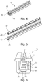
- FIGS Figures 4 to 6 Another floor rail 18 according to the invention with an outer rail 19 and an inner rail 20 are shown in FIGS Figures 4 to 6 .
- the bottom rail 18 differs from the bottom rail 1 solely in the different arrangement of recesses 21 in an inner rail bottom 22 of the inner rail 20 and an outer rail recess 23 in the outer rail 19 or in a rail bottom 24 of the outer rail 19.
Landscapes
- Engineering & Computer Science (AREA)
- Aviation & Aerospace Engineering (AREA)
- Transportation (AREA)
- Mechanical Engineering (AREA)
- Seats For Vehicles (AREA)
Abstract
Es wird eine Bodenschiene (1) für ein Fahrzeug vorgeschlagen, welche für die Anbringung einer Fahrzeug-Inneneinrichtung in einem Fahrzeug ausgebildet ist, wobei die Bodenschiene (1) hohl ist und eine Oberseite (4) mit einem Längsschlitz (5) aufweist. Erfindungsgemäß weist die Bodenschiene (1) über ihre Längserstreckung eine als Hohlprofil ausgebildete Außenschiene (2) auf mit in Längsrichtung der Bodenschiene (1) sich erstreckenden gegenüberliegenden Schienen-Längswänden und einem Schienenboden, wobei der Schienenboden der Oberseite (4) der Bodenschiene (1) gegenüberliegt und die Schienen-Längswände miteinander verbindet, und wobei eine Innenschiene (3) vorgesehen ist, die innerhalb der hohlen Außenschiene (2) aufgenommen ist, wobei die Außenschiene (2) aus einem ersten Werkstoff besteht und wobei die Innenschiene (3) aus einem zweiten Werkstoff besteht,wobei die Innenschiene (3) in einer Innenschienen-Wand (12, 13) mehrere Ausnehmungen (14, 15) umfasst, wobei in einer an die Innenschienen-Wand (12, 13) angrenzenden Schienen-Längswand (8, 9) der Außenschiene (2) eine Außenschienen-Ausnehmung (16, 17) vorhanden ist, wobei die Außenschienen-Ausnehmung (16, 17) an mehrere der Ausnehmungen (14, 15) in der Innenschienen-Wand (12, 13) anschließt, vorzugsweise an sämtliche der Ausnehmungen (14, 15) in der Innenschienen-Wand (12, 13) anschließt.A floor rail (1) for a vehicle is proposed which is designed for the attachment of a vehicle interior device in a vehicle, the floor rail (1) being hollow and having an upper side (4) with a longitudinal slot (5). According to the invention, the bottom rail (1) has, over its longitudinal extent, an outer rail (2) designed as a hollow profile with opposing longitudinal rail walls and a rail bottom, the rail bottom of the top (4) of the bottom rail (1) extending in the longitudinal direction of the bottom rail (1). opposite and connects the longitudinal walls of the rails to one another, and wherein an inner rail (3) is provided which is received within the hollow outer rail (2), the outer rail (2) being made of a first material and the inner rail (3) being made of a second material, the inner rail (3) comprising a plurality of recesses (14, 15) in an inner rail wall (12, 13), with a longitudinal rail wall (8, 9) adjoining the inner rail wall (12, 13) ) the outer rail (2) has an outer rail recess (16, 17), the outer rail recess (16, 17) adjoining several of the recesses (14, 15) in the inner rail wall (12, 13) closes, preferably adjoins all of the recesses (14, 15) in the inner rail wall (12, 13).
Description
Bei der Fertigstellung von Fahrzeugen im Hinblick auf unterschiedliche Einbauten wie zum Beispiel der Montage von Fahrzeug-Inneneinrichtungen wie eine Sitzanordnung und dergleichen sind technische und wirtschaftliche Gesichtspunkte zu berücksichtigen. Insbesondere ist es erwünscht, dass die hierfür im Fahrzeug zu schaffenden Voraussetzungen vorteilhaft herstellbar und einfach zu montieren sind. Häufig ist eine Schienenanordnung mit vorzugsweise mehrere Bodenschienen im Fahrzeug vorgesehen, die an einem Fahrzeugboden integral vorhanden oder nachträglich einbaubar ist.In the completion of vehicles with regard to different built-in components such as the assembly of vehicle interior equipment such as a seat arrangement and the like, technical and economic aspects must be taken into account. In particular, it is desirable that the prerequisites to be created for this in the vehicle can advantageously be produced and are easy to assemble. Frequently, a rail arrangement with preferably a plurality of floor rails is provided in the vehicle, which is present integrally on a vehicle floor or can be installed subsequently.
An der Fahrzeug-Bodenschiene sind die Einbauten anbringbar, vorzugsweise anpassbar in ihrer Einbau-Position entlang der Bodenschiene und daran lösbar fixierbar.The internals can be attached to the vehicle floor rail, preferably adaptable in their installation position along the floor rail and releasably fixed thereon.
Aufgabe der vorliegenden Erfindung ist es, eine Bodenschiene der eingangs genannten Art im Hinblick auf wirtschaftliche und technische Gesichtspunkte und bezüglich der Montage von Einbauten in einem Fahrzeug vorteilhaft bereitzustellen.The object of the present invention is to advantageously provide a floor rail of the type mentioned at the beginning with regard to economic and technical aspects and with regard to the installation of built-in components in a vehicle.
Diese Aufgabe wird durch die unabhängigen Ansprüche gelöst.This problem is solved by the independent claims.
In den abhängigen Ansprüchen sind zweckmäßige und vorteilhafte Ausgestaltungen der Erfindung aufgezeigt.Expedient and advantageous embodiments of the invention are shown in the dependent claims.
Die Erfindung geht aus von einer Bodenschiene für ein Fahrzeug, insbesondere von einer Fahrzeug-Bodenschiene. Die Bodenschiene ist für die Anbringung einer Fahrzeug-Inneneinrichtung und/oder einer Sitzanordnung oder anderer Einbauten in einem Fahrzeug wie einem PKW, einem Campingfahrzeug oder einem Kleintransporter ausgebildet, wobei die Bodenschiene hohl ist und eine Oberseite mit einem Längsschlitz aufweist. Hierfür sind bevorzugt mehrere vorzugsweise identische parallel im Fahrzeug vorhandene Bodenschienen z. B. zur Unterbringung einer Sitzanordnung vorgesehen. Die Bodenschienen verlaufen in ihrer Längserstreckung bevorzugt parallel zur Fahrzeuglängsachse. Die Bodenschienen können integral am Fahrzeugboden ausgebildet sein oder daran nachträglich eingebaut zum Beispiel angeschraubt oder angeschweißt sein. Die Anbindung der Inneneinrichtung bzw. z. B. der Fahrzeugsitzanordnung wie ein Einzelfahrzeugsitz oder eine Zweier- oder Dreier-Fahrzeugsitzbank erfolgt in der Regel an zumindest zwei parallelen Bodenschienen. Die Bodenschiene ist vorzugsweise kompakt bauend und weist eine Höhe und Breite im Zentimeterbereich auf, bei einer Länge im Meterbereich, je nach Länge des im Fahrzeug zu bestückenden Innenraums. Der Längsschlitz der Bodenschiene ist vorzugsweise durchgehend über die Länge der Bodenschiene ausgebildet.The invention is based on a floor rail for a vehicle, in particular a vehicle floor rail. The floor rail is designed for the attachment of a vehicle interior and / or a seat arrangement or other built-in components in a vehicle such as a car, a camping vehicle or a van, the floor rail being hollow and having a top side with a longitudinal slot. For this purpose, a plurality of preferably identical floor rails present in parallel in the vehicle z. B. provided for accommodating a seat arrangement. The floor rails preferably run parallel to the longitudinal axis of the vehicle in their longitudinal extension. The floor rails can be formed integrally on the vehicle floor or subsequently installed thereon, for example screwed or welded on. The connection of the interior or z. B. the vehicle seat arrangement such as a single vehicle seat or a two or three-seater vehicle bench is usually carried out on at least two parallel floor rails. The floor rail is preferably of compact construction and has a height and width in the centimeter range, with a length in the meter range, depending on the length of the interior space to be equipped in the vehicle. The longitudinal slot of the floor rail is preferably formed continuously over the length of the floor rail.
Der Kern der Erfindung liegt darin, dass die Bodenschiene über ihre Längserstreckung eine als Hohlprofil ausgebildete Außenschiene aufweist mit in Längsrichtung der Bodenschiene sich erstreckenden gegenüberliegenden Schienen-Längswänden und einem Schienenboden, wobei der Schienenboden der Oberseite der Bodenschiene gegenüberliegt und die Schienen-Längswände miteinander verbindet, und wobei eine Innenschiene vorgesehen ist, die innerhalb der hohlen Außenschiene aufgenommen ist, wobei die Außenschiene aus einem ersten Werkstoff besteht und wobei die Innenschiene aus einem zweiten Werkstoff besteht, wobei die Innenschiene in einer Innenschienen-Wand mehrere Ausnehmungen umfasst, wobei in einer an die Innenschienen-Wand angrenzenden Schienen-Längswand der Außenschiene eine Außenschienen-Ausnehmung vorhanden ist, wobei die Außenschienen-Ausnehmung an mehrere der Ausnehmungen in der Innenschienen-Wand anschließt, vorzugsweise an sämtliche der Ausnehmungen in der Innenschienen-Wand anschließt. Das zweite Material unterscheidet sich vom ersten Material. Damit wird eine Hybrid-Bodenschiene bereitgestellt, die im Hinblick auf die Fertigung bzw. Herstellung, Bearbeitung und technischen Eigenschaften verbessert ist gegenüber einer herkömmlichen insbesondere einer einheitlich aufgebauten bzw. aus genau einem Material bestehenden Bodenschiene.The essence of the invention lies in the fact that the floor rail has, over its longitudinal extent, an outer rail designed as a hollow profile with opposite longitudinal rail walls extending in the longitudinal direction of the floor rail and a rail base, the rail base being opposite the upper side of the floor rail and connecting the longitudinal rail walls to one another, and wherein an inner rail is provided which is received within the hollow outer rail, the outer rail being made of a first material and the inner rail being made of a second material, the inner rail comprising a plurality of recesses in an inner rail wall, one of which is connected to the Inner rail wall adjacent rail longitudinal wall of the outer rail one Outer rail recess is present, wherein the outer rail recess adjoins several of the recesses in the inner rail wall, preferably adjoins all of the recesses in the inner rail wall. The second material is different from the first material. A hybrid floor rail is thus provided which is improved in terms of production or manufacture, processing and technical properties compared to a conventional floor rail, in particular of a uniformly constructed or made of exactly one material.
Vorteilhafterweise weist die erfindungsgemäße Bodenschiene durch ihre Hybrid-Struktur eine gegenüber aus genau einem Material bzw. aus einheitlich aus zum Beispiel einem Stahlmaterial gebildeten Bodenschiene vergleichsweise höhere Festigkeit und/oder eine höhere Elastizität auf.Advantageously, due to its hybrid structure, the floor rail according to the invention has a comparatively higher strength and / or higher elasticity than a floor rail formed from exactly one material or from a uniformly formed steel material, for example.
Bei einer erfindungsgemäßen Bodenschiene mit einer daran befestigten Fahrzeug-Inneneinrichtung nimmt die Außenschiene bezogen auf die Nutzzustand im Fahrzeug vorteilhaft vergleichsweise hohe Kräfte und/oder Momente in vertikaler Richtung auf und die Innenschiene nimmt vorteilhaft vergleichsweise hohe Kräfte und/oder Momente in horizontaler Richtung auf.In the case of a floor rail according to the invention with a vehicle interior device attached, the outer rail advantageously absorbs comparatively high forces and / or moments in the vertical direction based on the usage state in the vehicle and the inner rail advantageously absorbs comparatively high forces and / or moments in the horizontal direction.
Insbesondere lässt sich die Bodenschiene bezüglich der Formgebung und Bearbeitung einerseits und der Belastbarkeit bzw. der mechanischen Stabilität andererseits optimal abstimmen. Vorzugsweise ist die Bodenschiene als Zweikomponenten-Bauteil aufgebaut mit einem äußeren Gehäuse aus dem ersten Werkstoff bzw. Material und einem Inneren, zum Beispiel einem Inlay aus dem zweiten Werkstoff. Vom Volumen der Bodenschiene macht die Außenschiene vorzugsweise den überwiegenden Anteil der Bodenschiene aus, zum Beispiel zwei Drittel. Vorzugsweise ist das erste Material härter als das zweite Material. Das zweite Material ist vorzugsweise leichter als das erste Material bzw. das zweite Material weist eine geringere Dichte auf als das erste Material.In particular, the bottom rail can be optimally coordinated with regard to the shaping and processing on the one hand and the loading capacity or mechanical stability on the other hand. The bottom rail is preferably constructed as a two-component component with an outer housing made of the first material or material and an interior, for example an inlay made of the second material. Of the volume of the bottom rail, the outer rail preferably makes up the majority of the bottom rail, for example two thirds. The first material is preferably harder than the second material. The second material is preferably lighter than the first material or the second material has a lower density than the first material.
Die Außenschiene bildet insbesondere die Außenform bzw. die Außenseite der Bodenschiene. Die Bodenschiene ist außerdem vorzugsweise ausgebildet für die Befestigung an einem Fahrzeugboden, beispielsweise mit Schrauböffnungen versehen. Der Längsschlitz der Bodenschiene ist dementsprechend insbesondere durch einen oberseitigen vorzugsweise durchgehende über die Länge bzw. nicht zwischen den beiden Enden der Schiene unterbrochenen Längsschlitz in der Außenschiene gebildet.The outer rail forms in particular the outer shape or the outer side of the floor rail. The floor rail is also preferably designed for attachment to a vehicle floor, for example provided with screw openings. The longitudinal slot of the bottom rail is accordingly formed in particular by a longitudinal slot in the outer rail that is preferably continuous over the length or not interrupted between the two ends of the rail.
In einem von der Außenschiene gebildeten Schienenhohlraum ist die Innenschiene vorzugsweise komplett untergebracht, zum Beispiel stirnseitig an der Außenschiene eingeschoben. Die Länge der Außenschiene und die Länge der Innenschiene sind zumindest im Wesentlichen gleich. Die Innenschiene grenzt mit ihrer Außenseiten an den Schienenboden und an zumindest eine Schienen-Längswand an, wenn die Innenschiene L-förmig ist. Vorzugsweise ist die Innenschiene U-förmig und grenzt mit ihren gegenüberliegenden freien Schenkeln innen an beide Schienen-Längswände der Außenschiene an. Die Innenschiene weist vorzugsweise einen Innenschienen-Boden und eine Innenschienen-Wand auf, wobei der Innenschienen-Boden und die Innenschienen-Wand abgewinkelt zueinander ausgerichtet sind. Die Bodenschiene ist als Verbund- bzw. Hybrid-Schiene bzw. als Hybridmaterial-Schiene gestaltet aus einem Materialmix, wobei die Außenschiene einheitlich aus dem ersten Material besteht und die Innenschiene einheitlich aus dem zweiten Material besteht.The inner rail is preferably completely accommodated in a rail cavity formed by the outer rail, for example pushed in at the end of the outer rail. The length of the outer rail and the length of the inner rail are at least essentially the same. The outer side of the inner rail adjoins the rail base and at least one rail longitudinal wall when the inner rail is L-shaped. The inner rail is preferably U-shaped and, with its opposing free legs, adjoins the inside of both rail longitudinal walls of the outer rail. The inner rail preferably has an inner rail base and an inner rail wall, the inner rail base and the inner rail wall being aligned at an angle to one another. The bottom rail is designed as a composite or hybrid rail or as a hybrid material rail made of a mix of materials, the outer rail being made uniformly from the first material and the inner rail being made uniformly from the second material.
Die Außenschiene umfasst den oberseitigen Längsschlitz, wobei dieser oberhalb einer oben offenen Seite der z. B. U-förmigen Innenschiene vorhanden ist. Damit wird ein von oben zugängliches Hohlvolumen der Bodenschiene mit einem von oben betrachtet Hinterschnittbereich bereitgestellt.The outer rail comprises the longitudinal slot on the top, this being above an open-topped side of the z. B. U-shaped inner rail is present. This provides a hollow volume of the floor rail that is accessible from above and has an undercut area viewed from above.
Der Werkstoff der Außenschiene ist vorzugsweise leichter als der vergleichsweise härtere Werkstoff der Innenschiene, was hinsichtlich einer Abnutzung und einer maximalen Belastbarkeit der Bodenschiene in einem Belastungsfall wie einem Unfall- oder Crash-Szenario des Fahrzeugs mit z. B. einem über erfindungsgemäße Bodenschienen fixierten Fahrzeugsitz von Vorteil ist.The material of the outer rail is preferably lighter than the comparatively harder material of the inner rail, which in terms of wear and a maximum load capacity of the bottom rail in a load such as an accident or crash scenario of the vehicle with z. B. a vehicle seat fixed on floor rails according to the invention is advantageous.
Die Außenschiene umfasst die Oberseite der Bodenschiene mit einem den Längsschlitz begrenzenden Stützabschnitt. Der Stützabschnitt ist vorzugsweise über die gesamte Länge der Außenschiene beidseitig des Längsschlitzes vorhanden.The outer rail comprises the top of the bottom rail with a support section delimiting the longitudinal slot. The support section is preferably present over the entire length of the outer rail on both sides of the longitudinal slot.
Die Erfindung geht weiter davon aus, dass die Bodenschiene über ihre Längserstreckung eine als Hohlprofil ausgebildete Außenschiene aufweist mit in Längsrichtung der Bodenschiene sich erstreckenden gegenüberliegenden Schienen-Längswänden und einem Schienenboden, wobei der Schienenboden der Oberseite der Bodenschiene gegenüberliegt und die Schienen-Längswände miteinander verbindet, und wobei eine Innenschiene vorgesehen ist, die innerhalb der hohlen Außenschiene aufgenommen ist, wobei die Außenschiene aus einem ersten Werkstoff besteht und wobei die Innenschiene aus einem zweiten Werkstoff besteht, wobei die Innenschiene im Innenschienen-Boden mehrere Ausnehmungen umfasst, die in Längsrichtung der Innenschiene voneinander beabstandet vorhanden sind, wobei in einem Schienenboden der Außenschiene eine Schienenboden-Ausnehmung vorhanden ist, wobei die Schienenboden-Ausnehmung an sämtliche der Ausnehmungen im Innenschienen-Boden anschließt. Die Schienenboden-Ausnehmung in der Außenschiene kann durch mehrere voneinander getrennte Einzelausnehmungen gebildet sein oder als eine durchgehende Nut oder als durchgehender Kanal.The invention is further based on the assumption that the floor rail has, over its longitudinal extent, an outer rail designed as a hollow profile with opposite longitudinal rail walls extending in the longitudinal direction of the floor rail and a rail base, the rail base being opposite the upper side of the floor rail and connecting the longitudinal rail walls to one another, and wherein an inner rail is provided, which is received within the hollow outer rail, wherein the outer rail consists of a first material and wherein the inner rail consists of a second material, wherein the inner rail in the inner rail base comprises a plurality of recesses, which are in the longitudinal direction of the inner rail from each other spaced apart, wherein a rail floor recess is present in a rail floor of the outer rail, the rail floor recess adjoining all of the recesses in the inner rail floor. The rail floor recess in the outer rail can be formed by several separate recesses or as a continuous groove or as a continuous channel.
Dann sind vorzugsweise keine Ausnehmungen in einer Innenschienen-Wand und einer Schienen-Längswand vorgesehen.Then preferably no recesses are provided in an inner rail wall and a rail longitudinal wall.
Es ist von Vorteil, wenn die Außenschiene und die Innenschiene fest miteinander verbunden sind. Die beiden Schienen sind insbesondere nach deren Zusammenfügen lösbar oder dauerhaft miteinander verbunden z. B. vernietet, verschweißt, verschraubt und/oder verklemmt. Damit wird eine mechanisch hoch belastbare Bodenschiene bereitgestellt. Die Bodenschiene ist insbesondere in Längsrichtung der Bodenschiene und quer dazu vergleichsweise hoch stabil bzw. auf Zug und/oder Druck belastbar.It is advantageous if the outer rail and the inner rail are firmly connected to one another. The two rails are detachably or permanently connected to one another, in particular after they have been joined, for. B. riveted, welded, screwed and / or clamped. This provides a floor rail that can withstand high mechanical loads. The bottom rail is comparatively highly stable, particularly in the longitudinal direction of the bottom rail and transversely thereto, or can be subjected to tension and / or pressure.
Vorteilhaft ist die Außenschiene aus einem Leichtmetallwerkstoff wie beispielsweise einem Aluminiumwerkstoff gebildet.The outer rail is advantageously formed from a light metal material such as an aluminum material.
Das Außenschienen-Material bzw. der erste Werkstoff hat eine Dichte vorzugsweise unter 5,0 g/cm3. Vorzugsweise besteht die Außenschiene aus einem Aluminium-Material bzw. aus einer Aluminium-Legierung.The outer rail material or the first material has a density preferably below 5.0 g / cm 3 . The outer rail preferably consists of an aluminum material or an aluminum alloy.
Gemäß einer anderen vorteilhaften Modifikation der Erfindung ist die Außenschiene ein Strangpressprofil. Damit ist die Herstellung der Außenschiene vorzugsweise aus einem wirtschaftlich und technisch gut schmelzbaren Metallwerkstoff wie einem Aluminium-Werkstoff einfach und wirtschaftlich möglich.According to another advantageous modification of the invention, the outer rail is an extruded profile. The production of the outer rail is thus possible in a simple and economical manner, preferably from an economically and technically easily fusible metal material such as an aluminum material.
Es ist überdies von Vorteil, wenn die Innenschiene aus einem Stahlmaterial gebildet ist. Eine Innenschiene aus Stahl vorzugsweise aus einem Edelstahl-Material bzw. Edelstahl-Blechmaterial ist korrosionsbeständig, stabil und wirtschaftlich vorteilhaft herstellbar und umformbar durch gängige Umform-Verfahren. Ein Edelstahlmaterial weist vorzugsweise eine zu anderen Metallen bzw. zu einem Leichtmetall vergleichsweise hohe Härte auf und ist damit im Hinblick auf ein Abnutzungs- und Verschleißverhalten vorteilhaft. Ein praxisrelevantes Ausschaffen von aufgrund der Verrastung beanspruchter Konturen der Innenschiene wie Ränder der Ausnehmungen wird so verhindert.It is also advantageous if the inner rail is formed from a steel material. An inner rail made of steel, preferably made of a high-grade steel material or high-grade steel sheet material, is corrosion-resistant, stable and economically advantageous to manufacture and transformable by common forming processes. A stainless steel material preferably has a hardness that is comparatively high to that of other metals or to a light metal and is therefore advantageous with regard to wear and tear. A practice-relevant creation of contours of the inner rail that are stressed due to the latching, such as the edges of the recesses, is thus prevented.
Eine alternative vorteilhafte Ausbildung der Erfindung zeichnet sich dadurch aus, dass die Innenschiene als Blech-Kantprofil ausgebildet ist. Damit ist die Herstellung mit einem Biege- oder einem anderen Umformprozess aus einem standardmäßig in einer Vielzahl von Sorten bereitstellbaren Blechmaterial vorteilhaft möglich. Vorzugsweise ist die Innenschiene exakt und mit hoher Maßgenauigkeit z. B. aus einem Laser- und/oder Stanz-Blechbauteil gebildet. Dies ist zudem vergleichsweise kostengünstig in der Produktion.An alternative advantageous embodiment of the invention is characterized in that the inner rail is a sheet metal edge profile is trained. Production with a bending or other forming process from a standard sheet metal material that can be provided in a large number of types is thus advantageously possible. Preferably, the inner rail is exact and with high dimensional accuracy, for. B. formed from a laser and / or stamped sheet metal component. This is also comparatively inexpensive to produce.
Nach einer weiteren vorteilhaften Modifikation der Erfindung weist die Innenschiene einen Innenschienen-Boden und eine Innenschienen-Wand auf, wobei der Innenschienen-Boden und die Innenschienen-Wand abgewinkelt zueinander ausgerichtet sind. Damit ist die Herstellung der Innenschiene aus einem flächigen einstückigen Rohling wie einem Blech zu einem Kant- bzw. Biegeteil mit zueinander winklig ausgerichteten Abschnitten vorteilhaft möglich. Mit der zum Boden abgewinkelten Wand wird eine hohe Steifigkeit und Verwindungsstabilität der Innenschiene und damit der Bodenschiene ermöglicht.According to a further advantageous modification of the invention, the inner rail has an inner rail base and an inner rail wall, the inner rail base and the inner rail wall being aligned at an angle to one another. In this way, the production of the inner rail from a flat, one-piece blank such as a sheet metal to form an edge or bent part with sections oriented at an angle to one another is advantageously possible. With the wall angled to the floor, a high degree of rigidity and torsional stability of the inner rail and thus the floor rail is made possible.
Ein Vorteil ergibt sich, wenn die Innenschiene U-förmig im Querschnitt ausgebildet ist mit einem Innenschienen-Boden und jeweils einer Innenschienen-Wand beidseitig des in Längsrichtung verlaufenden Innenschienen-Bodens. Die Innenschiene ist vorzugsweise mit ihrer Außenform an eine Innenform passend abgestimmt, wobei Innenform das hohle Innenvolumen der Außenschiene umgibt. Die Innenschiene kleidet damit einen vorzugsweise überwiegenden Bereich der Innenoberfläche der Außenschien aus. Die Innenschiene bildet einen innenliegenden harten Oberflächenschutz der Außenschiene.An advantage is obtained if the inner rail is U-shaped in cross section with an inner rail base and an inner rail wall on both sides of the inner rail base running in the longitudinal direction. The outer shape of the inner rail is preferably matched to an inner shape, the inner shape surrounding the hollow inner volume of the outer rail. The inner rail thus lines a preferably predominant area of the inner surface of the outer rail. The inner rail forms an internal hard surface protection of the outer rail.
Die Innenschiene ist mit vergleichsweise geringem Materialeinsatz herstellbar. Die Innenschiene ist geeignet, flächig anschmiegend an Innenseiten der hohlen U-förmigen Außenschiene mit dieser verbunden zu werden, was eine kompakte und mechanisch hoch stabile Zweikomponenten-Struktur ermöglicht.The inner rail can be produced with a comparatively small amount of material. The inner rail is suitable for being connected to the inner sides of the hollow U-shaped outer rail in a flush manner, which enables a compact and mechanically highly stable two-component structure.
Gemäß einer vorteilhaften Variante der Erfindung weist die Innenschiene und/oder die Außenschiene eine Rastkontur auf, zur Fixierung eines an der Bodenschiene anbringbaren Rastbauteils wie eines Schlittens. Die Rastkontur und das Rastbauteil sind vorzugsweise ein Teil einer Anbring- und/oder Verriegelungsanordnung. Der Schlitten dient zur Anbringung einer Einbauanordnung wie einer Sitzanordnung in einem Fahrzeug an der im Fahrzeug vorhandenen Bodenschiene. Der Schlitten und die Bodenschiene sind vorzugsweise so aufeinander abgestimmt, dass die Bodenschiene und der mit einer Einbauvorrichtung verbindbare Schlitten, der z. B. mit einer Unterkonstruktion einer Fahrzeugsitzanordnung verbindbar ist, über eine Verriegelungsanordnung lösbar entlang der Bodenschiene in unterschiedlichen Längspositionen der Bodenschiene verrastbar ist. Dabei dient die Rastkontur zum eingreifenden Verrasten eines Verriegelungselements der Verriegelungsanordnung. Die Verrastung ist lösbar aber gesichert.According to an advantageous variant of the invention, the inner rail and / or the outer rail has a latching contour for fixing a latching component such as a slide that can be attached to the bottom rail. The latching contour and the latching component are preferably part of a mounting and / or locking arrangement. The slide is used to attach an installation arrangement such as a seat arrangement in a vehicle to the floor rail present in the vehicle. The slide and the bottom rail are preferably coordinated so that the bottom rail and the slide connectable to a mounting device, the z. B. can be connected to a substructure of a vehicle seat arrangement, can be releasably latched via a locking arrangement along the floor rail in different longitudinal positions of the floor rail. The latching contour is used for engaging latching of a locking element of the locking arrangement. The locking is releasable but secured.
Da der Längsschlitz in der Bodenschiene bzw. der Außenschiene vorzugsweise durchgehend bzw. ohne Unterbrechung ausgebildet ist, ist der Schlitten entlang der Bodenschiene bzw. oberseitig daran, wobei sich der Schlitten unterseitig an der Oberseite bzw. der Bodenschiene abstützt, an der Bodenschiene vorzugsweise über deren komplette Länge bzw. in Längsrichtung entlang der Bodenschiene hin- und herverfahrbar. Dabei kann aufgrund des durchgehenden Längsschlitzes ein Abschnitt des nicht verrasteten Schlittens in den materialfreien Bereich des Längsschlitzes bzw. zwischen den Stegen eingreifen.Since the longitudinal slot in the bottom rail or the outer rail is preferably formed continuously or without interruption, the slide is along the bottom rail or on the top side thereof, the slide being supported on the bottom side on the top side or the bottom rail, on the bottom rail preferably via the bottom rail complete length or in the longitudinal direction can be moved back and forth along the bottom rail. Due to the continuous longitudinal slot, a section of the non-latched slide can engage in the material-free area of the longitudinal slot or between the webs.
An der Oberseite der Bodenschiene ist der zur Bodenschiene passende Schlitten einer zum Beispiel Anbringvorrichtung abstützbar. Der Schlitten ist zum Beispiel Teil der Anbringvorrichtung für eine Sitzanordnung in einem Fahrzeug, wobei die Bodenschiene Teil der Vorrichtung sein kann. Der Schlitten ist mit Hilfe des Verriegelungselements der Verriegelungsanordnung an der Bodenschiene lösbar fixierbar bzw. verrastbar.On the upper side of the floor rail, the slide that matches the floor rail can be supported by an attachment device, for example. The carriage is, for example, part of the attachment device for a seat arrangement in a vehicle, wherein the floor rail can be part of the device. The slide can be releasably fixed or latched on the floor rail with the aid of the locking element of the locking arrangement.
Vorteilhaft umfasst die Innenschiene in zumindest einer Innenschienen-Wand mehrere Ausnehmungen, die in Längsrichtung der Innenschiene voneinander beabstandet vorhanden sind. Mit den vorzugsweise untereinander identischen Ausnehmungen kann ein zu einer Ausnehmung passender Verriegelungselement der Verriegelungsanordnung zusammenwirken, um den Schlitten an der Bodenschiene lösbar zu fixieren. Das Verriegelungselement kann hierzu verstellbar entweder in eine Ausnehmung eingreifen, was den Verriegelungszustand des Schlittens an der Bodenschiene bedeutet, oder aus der Ausnehmung herausbewegt sein, dann ist der Schlitten nicht verriegelt an der Bodenschiene. Im nicht verriegelten Zustand des Schlittens ist der Schlitten an der Bodenschiene entlangbewegbar bzw. von der Bodenschiene nach oben abhebbar.The inner rail advantageously comprises a plurality of recesses in at least one inner rail wall, which are present at a distance from one another in the longitudinal direction of the inner rail. A locking element of the locking arrangement that matches a recess can interact with the recesses, which are preferably identical to one another, in order to releasably fix the slide on the floor rail. For this purpose, the locking element can adjustably either engage in a recess, which means the locked state of the slide on the floor rail, or be moved out of the recess, then the slide is not locked on the floor rail. In the unlocked state of the slide, the slide can be moved along the bottom rail or lifted upwards from the bottom rail.
Die Ausnehmungen sind vorzugsweise durch das Material der Innenschienen-Wand durchgehend, also ein materialfreies Loch bildend. Die Ausnehmungen sind zum Beispiel mehreckig bzw. fensterartig.The recesses are preferably continuous through the material of the inner rail wall, that is to say they form a material-free hole. The recesses are, for example, polygonal or window-like.
Die Ausnehmungen sind vorzugsweise regelmäßig beabstandet und gleichartig bzw. genau gegenüberliegend in einer Innenschienen-Wand vorhanden, vorzugsweise sind entsprechende Ausnehmungen in beiden gegenüberliegenden Innenschienen-Wänden vorhanden.The recesses are preferably regularly spaced and similar or exactly opposite to one another in an inner rail wall, preferably corresponding recesses are present in both opposite inner rail walls.
Die Ausnehmungen sind vorzugsweise aus z. B. einem dünnen zum Beispiel Edelstahl- bzw. Stahl-Blechabschnitt der Innenschienen-Wand herausgearbeitet durch ein schneidendes, stanzendes und/oder spanabhebendes Verfahren.The recesses are preferably made of, for. B. a thin, for example, stainless steel or sheet steel section of the inner rail wall worked out by a cutting, punching and / or machining process.
Es kann zudem von Vorteil sein, wenn die Innenschiene im Innenschienen-Boden mehrere Ausnehmungen umfasst, die in Längsrichtung der Innenschiene voneinander beabstandet vorhanden sind. Damit kann die Verriegelungswirkung in der Bodenschiene allein oder zusätzlich zu einer Verriegelung an der Innenschienen-Wand im Bereich des Innenschienen-Bodens erfolgen.It can also be advantageous if the inner rail in the inner rail base comprises a plurality of recesses which are present at a distance from one another in the longitudinal direction of the inner rail. In this way, the locking effect in the bottom rail can take place alone or in addition to a locking on the inner rail wall in the area of the inner rail bottom.
Vorzugsweise sind bei vorhandenen Ausnehmungen im Innenschienen-Boden dann in weiteren Abschnitten der Innenschiene keine Ausnehmungen vorgesehen, insbesondere keine Ausnehmungen in einer Innenschienen-Wand bzw. keine Ausnehmungen in beiden gegenüberliegenden Innenschienen-Wänden. Vorteilhafterweise umfasst die Innenschiene in einer Innenschienen-Wand mehrere Ausnehmungen, wobei in einer an die Innenschienen-Wand angrenzenden Schienen-Längswand der Außenschiene eine Außenschienen-Ausnehmung vorhanden ist, welche an eine Ausnehmung in der Innenschienen-Wand anschließt. Eine durch Materialwegnahme gewonnene Eingreif-Tiefe der Bodenschiene für ein Verriegelungselement ist damit größer verglichen mit einer Ausnehmung allein in der vergleichsweise dünnen Innenschiene, womit eine Eingreiftiefe ggf. zu gering wäre bzw. maximal im Maß der Dicke der Innenschien möglich wäre. Mit der zusätzlichen Ausnehmung in der Außenschiene wird mehr Raum zum Durchgreifen und/oder ein größere Tiefe zum Einhaken eines Verriegelungselements an der Bodenschiene bereitgestellt. Die Eintauchtiefe für das Verriegelungselement ergibt sich dann aus der Tiefe der Ausnehmung in der Innenschiene plus der Tiefe der dahinter liegenden anschließenden Tiefe der Außenschienen-Ausnehmung. Vorzugsweise ist jeder Ausnehmung der Innenschiene eine dazugehörige Ausnehmung in der Außenschien zugeordnet bzw. sind die Ausnehmungen immer paarweise benachbart vorhanden. Das eingreifende Verrieglungselement greift im Verriegelungszustand des Schlittens von innen in die dazugehörige vergrößerte Ausnehmung an Innen- und Außenschiene.If there are recesses in the inner rail base, then preferably no recesses are provided in further sections of the inner rail, in particular no recesses in one inner rail wall or no recesses in both opposing inner rail walls. The inner rail advantageously comprises a plurality of recesses in an inner rail wall, an outer rail recess being present in a longitudinal wall of the outer rail adjoining the inner rail wall, which is connected to a recess in the inner rail wall. An engagement depth of the bottom rail for a locking element obtained by removing material is thus greater compared to a recess alone in the comparatively thin inner rail, which means that an engagement depth would possibly be too small or at most possible to the extent of the thickness of the inner rail. The additional recess in the outer rail provides more space for reaching through and / or a greater depth for hooking a locking element onto the bottom rail. The immersion depth for the locking element then results from the depth of the recess in the inner rail plus the depth of the subsequent depth of the outer rail recess lying behind it. Each recess of the inner rail is preferably assigned an associated recess in the outer rail or the recesses are always present in adjacent pairs. In the locked state of the slide, the engaging locking element engages from the inside into the associated enlarged recess on the inner and outer rails.
Eine durchgehende z.B. kanalförmige Ausnehmung ist vorteilhaft bereitstellbar mit der Herstellung der Außenschiene als Strangpressprofil gegenüber ausgesparten fensterartigen offenen Ausnehmungen in der Außenschiene aus Aluminium, da diese in einem Alumaterial zeitaufwändig bzw. kostenintensiv spanabhebend gefräst oder gebohrt werden müssen.A continuous, e.g., channel-shaped recess can advantageously be provided with the production of the outer rail as an extruded profile compared to recessed window-like open recesses in the outer rail made of aluminum, since these have to be milled or drilled in an aluminum material in a time-consuming or costly manner.
Es ist dabei vorteilhaft, dass in einem Verriegelungszustand z. B. eines Schlittens an der Bodenschiene, die gesamt zur Verfügung stehende Eintauchtiefe für das Verriegelungselement sich vorteilhaft aus der Tiefe einer jeweiligen Ausnehmung in der Innenschiene und aus der Tiefe der Außenschienen-Ausnehmung zusammensetzt, wobei die Tiefe der Außenschienen-Ausnehmung in der Regel größer ist als die Tiefe der Innenschienen-Ausnehmung, welche der Wandstärke bzw. der Dicke der Innenschiene entspricht.It is advantageous that in a locked state, for. B. a slide on the bottom rail, the total for The depth of immersion available for the locking element is advantageously composed of the depth of a respective recess in the inner rail and the depth of the outer rail recess, the depth of the outer rail recess generally being greater than the depth of the inner rail recess, which is the wall thickness or corresponds to the thickness of the inner rail.
Bevorzugt sind mehrere voneinander getrennte Ausnehmungen in einer oder beiden Innenschienen-Wänden vorhanden, wobei eine durchgehende bzw. nicht unterbrochene Außenschienen-Ausnehmung der Innenschienen-Wand einer Außenschienen-Wand vorhanden ist, so dass hinter jeder Ausnehmung der Innenschiene eine Ausnehmung der Außenschiene unmittelbar anschließt. Die Außenschienen-Ausnehmung ist vorzugsweise als durchgehende Vertiefung zum Beispiel kanal- oder nutförmig in der Außenschiene bzw. in den beiden Schienen-Längswänden vorhanden. Die Außenschienen-Ausnehmung bzw. die Vertiefung ist demgemäß vorzugsweise kein Schlitz oder Spalt in der Außenschiene, es bleibt vorzugsweise ein Restbodenstärke vorhanden, sondern ist bevorzugt eine rinnenartige Vertiefung zum Beispiel eine innenseitige längliche durchgehende Vertiefung. Die Breite der Vertiefung entspricht vorzugsweise der Breite der jeweiligen Ausnehmungen. Mit der rinnenartigen durchgehenden Ausnehmung in der Schienen-Längswand der Außenschiene auch hinter nicht ausgenommenen Bereichen der Innenschiene zwischen zwei benachbarten Ausnehmungen vorhanden ist.There are preferably several separate recesses in one or both inner rail walls, with a continuous or uninterrupted outer rail recess in the inner rail wall of an outer rail wall so that a recess in the outer rail directly adjoins each recess in the inner rail. The outer rail recess is preferably present as a continuous recess, for example in the form of a channel or groove, in the outer rail or in the two rail longitudinal walls. The outer rail recess or the depression is accordingly preferably not a slot or gap in the outer rail, a residual base thickness preferably remains, but is preferably a channel-like depression, for example an elongated, continuous depression on the inside. The width of the recess preferably corresponds to the width of the respective recesses. With the channel-like continuous recess in the longitudinal wall of the rails, the outer rail is also present behind non-recessed areas of the inner rail between two adjacent recesses.
Gemäß einer Abwandlung der Erfindung umfasst die Innenschiene eine erste Innenschienen-Wand mit mehreren Ausnehmungen und eine zweite gegenüberliegenden Innenschienen-Wand mit mehreren Ausnehmungen, wobei in einer an die erste Innenschienen-Wand angrenzende ersten Schienen-Längswand der Außenschiene eine erste Außenschienen-Ausnehmung vorhanden ist, wobei die erste Außenschienen-Ausnehmung an sämtliche der Ausnehmungen in der ersten Innenschienen-Wand anschließt, und wobei in einer an die zweite Innenschienen-Wand angrenzende zweite Schienen-Längswand der Außenschiene eine zweite Außenschienen-Ausnehmung vorhanden ist, wobei die zweite Außenschienen-Ausnehmung an sämtliche der Ausnehmungen in der zweiten Innenschienen-Wand anschließt.According to a modification of the invention, the inner rail comprises a first inner rail wall with several recesses and a second opposing inner rail wall with several recesses, a first outer rail recess being present in a first longitudinal wall wall of the outer rail adjoining the first inner rail wall wherein the first outer rail recess adjoins all of the recesses in the first inner rail wall, and wherein a second outer rail recess is present in a second longitudinal rail wall of the outer rail adjoining the second inner rail wall is, wherein the second outer rail recess adjoins all of the recesses in the second inner rail wall.
Die Außenschienen-Ausnehmungen sind vorzugsweise über die gesamte Länge der Außenschiene durchgehend z. B. rinnen- oder kanalförmig ausgebildet. Vorzugsweise sind dann keine Ausnehmungen im Innenschienen-Boden und im Schienenboden der Außenschiene vorgesehen.The outer rail recesses are preferably continuously z. B. channel or channel-shaped. Preferably, no recesses are then provided in the inner rail base and in the rail base of the outer rail.
Die Erfindung erstreckt sich auch auf eine Vorrichtung zur Anbringung einer Fahrzeug-Inneneinrichtung und/oder einer Sitzanordnung in einem Fahrzeug, wobei die Vorrichtung einen mit der Sitzanordnung verbindbaren Schlitten und eine Bodenschiene nach einer der vorhergehenden Ausbildungen aufweist.The invention also extends to a device for attaching a vehicle interior and / or a seat arrangement in a vehicle, the device having a slide that can be connected to the seat arrangement and a floor rail according to one of the preceding embodiments.
Von Vorteil ist es, dass eine Verriegelungsanordnung der Anbringvorrichtung Ausnehmungen umfasst, die in Längsrichtung der Bodenschiene voneinander beabstandet vorhanden sind, und ein Verriegelungselement der Verriegelungsanordnung einen Riegelabschnitt und einen Anlageabschnitt derart aufweist, dass bei der Fixierung des Schlittens der Riegelabschnitt in eine Ausnehmung in der Bodenschiene eintaucht und der Anlageabschnitt an einer Innenseite des Stützabschnitts in Anlage kommt, so dass im verriegelten Zustand mit dem Riegelabschnitt eine Bewegung des Schlittens in Längsrichtung der Bodenschiene blockiert ist und mit dem Anlageabschnitt ein Abheben des Schlittens von der Bodenschiene unterbunden ist.It is advantageous that a locking arrangement of the attachment device comprises recesses which are spaced apart from one another in the longitudinal direction of the bottom rail, and a locking element of the locking arrangement has a locking section and a contact section such that when the carriage is fixed, the locking section is in a recess in the bottom rail immersed and the contact section comes into contact with an inside of the support section, so that in the locked state with the locking section, movement of the slide in the longitudinal direction of the floor rail is blocked and the contact section prevents the slide from lifting off the floor rail.
Der Schlitten ist an der Bodenschiene anordenbar und im angeordneten aber nicht verriegelten bzw. nicht verrasteten Zustand in Längsrichtung der Bodenschiene bewegbar und an unterschiedlichen Stellen in Längsrichtung der Bodenschiene fixierbar. Die Bodenschiene ist vorzugsweise als Hohlprofil mit in Längsrichtung der Bodenschiene sich erstreckenden gegenüberliegenden Schienen-Längswänden ausgebildet. Zwischen den Schienen-Längswänden weist die Außenschiene einen Schienenhohlraum der Bodenschiene mit der Innenschiene auf. Die Bodenschiene weist einen Längsschlitz mit einem den Längsschlitz begrenzenden Stützabschnitt auf. Der Stützabschnitt weist eine Außenseite auf, an der sich der Schlitten im angeordneten Zustand des Schlittens an der Bodenschiene abstützt, wobei der Stützabschnitt eine der Außenseite gegenüberliegende Innenseite aufweist, die an den Schienenhohlraum angrenzt, wobei zur Fixierung des an der Bodenschiene angebrachten Schlittens eine Verriegelungsanordnung mit einem am Schlitten verstellbar aufgenommenen Verriegelungselement vorgesehen ist.The slide can be arranged on the floor rail and, in the arranged but not locked or not locked state, can be moved in the longitudinal direction of the floor rail and can be fixed at different points in the longitudinal direction of the floor rail. The floor rail is preferably designed as a hollow profile with opposite longitudinal rail walls extending in the longitudinal direction of the floor rail. Between the rail longitudinal walls, the outer rail has a rail cavity of the bottom rail with the inner rail. The The bottom rail has a longitudinal slot with a support section delimiting the longitudinal slot. The support section has an outside on which the slide is supported in the arranged state of the slide on the floor rail, the support section having an inside opposite the outside, which adjoins the rail cavity, with a locking arrangement for fixing the slide attached to the floor rail a locking element adjustably received on the slide is provided.
Vorzugsweise ist an einem Verriegelungselement ein Riegelabschnitt oder bevorzugt sind mehrere zueinander versetzte Riegelabschnitte vorhanden, welche derart ausgebildet sind, dass bei der Fixierung des Schlittens an der Bodenschiene ein Riegelabschnitt in eine jeweilige Ausnehmung in der dazugehörigen Schienen-Längswand der Bodenschiene eingreift.There is preferably a locking section on a locking element or preferably several locking sections offset from one another, which are designed in such a way that when the carriage is fixed to the floor rail, a locking section engages in a respective recess in the associated rail longitudinal wall of the floor rail.
Schließlich wird gemäß der vorliegenden Erfindung ein Fahrzeug mit einem Fahrzeugboden vorgeschlagen, wobei eine Vorrichtung wie vorgenannt beschrieben vorhanden ist.Finally, according to the present invention, a vehicle with a vehicle floor is proposed, with a device as described above being present.
Weitere Merkmale und Vorteile der Erfindung sind anhand von in den Figuren stark schematisiert dargestellten Ausführungsbeispielen einer erfindungsgemäßen Bodenschiene näher erläutert.Further features and advantages of the invention are explained in greater detail on the basis of exemplary embodiments of a floor rail according to the invention which are shown in a highly schematic manner in the figures.
Im Einzelnen zeigt:
-
Fig. 1 eine perspektivische Ansicht schräg von oben auf einen vorderen Endabschnitt einer erfindungsgemäßen Bodenschiene, -
Fig. 2 einen Ausschnitt einer Bodenschiene gemäßFig. 1 in Explosionsdarstellung, -
Fig. 3 eine perspektivische Frontansicht auf ein vorderes Ende der Bodenschiene gemäßFig. 1 , -
Fig. 4 eine perspektivische Ansicht schräg von oben auf einen vorderen Endabschnitt einer weiteren erfindungsgemäßen Bodenschiene, -
Fig. 5 einen Ausschnitt einer Bodenschiene gemäßFig. 4 in Explosionsdarstellung und -
Fig. 6 eine perspektivische Frontansicht auf ein vorderes Ende der Bodenschiene gemäßFig. 4 .
-
Fig. 1 a perspective view obliquely from above of a front end portion of a floor rail according to the invention, -
Fig. 2 a section of a floor rail according toFig. 1 in exploded view, -
Fig. 3 a perspective front view of a front end of the floor rail according to FIGFig. 1 , -
Fig. 4 a perspective view obliquely from above of a front end portion of a further floor rail according to the invention, -
Fig. 5 a section of a floor rail according toFig. 4 in exploded view and -
Fig. 6 a perspective front view of a front end of the floor rail according to FIGFig. 4 .
Eine erfindungsgemäße Bodenschiene 1 für ein Fahrzeug (nicht dargestellt) zeigt
Die bevorzugt als Fahrzeug-Bodenschiene ausgebildete Bodenschiene 1 umfasst eine Außenschiene 2 und eine Innenschiene 3. Die Bodenschiene 1 ist als Hybridschiene gebildet aus einem Materialmix bzw. aus einer Leichtmetallschiene als Außenschiene 2 und einer als Inlayschiene gestalteten Innenschiene 3 aus einem Edelstahlmaterial. Die Außenschiene 2 besteht zum Beispiel aus einem Aluminiummaterial und ist ein Strangpressprofil. Die Innenschiene 3 ist hier ein aus einem Blech gebildetes Biegeteil vorzugsweise ein Edelstahl-Kantprofil.The
Die Bodenschiene 1 ist hohl und weist eine von der Außenschiene 2 gebildete Oberseite 4 mit einem Längsschlitz 5 auf, wobei der Längsschlitz 5 beidseitig von Stegen 6 und 7 der Außenschiene 2 begrenzt wird. Die Stege 6, 7 bilden mit ihren fluchtenden Außenseiten die ebene flache Oberseite 4 der Bodenschiene 1. Die jeweiligen äußeren, dem Längsschlitz 5 gegenüberliegenden Längsseiten der Stege 6 und 7 sind konvex geformt bzw. sind mit einem Radius nach außen abfallend zur von der Oberseite 4 aufgespannten Ebene gestaltet.The
Die Außenschiene 2 weist außerdem gegenüberliegende Schienen-Längswände 8 und 9 und einen die Schienen-Längswände 8 und 9 verbindenden Schienenboden 10 auf.The
Die Innenschiene 3 weist eine nach oben bzw. zum Längsschlitz 5 hin offene U-Form auf mit einem Innenschienen-Boden 11 und zwei daran rechtwinklig nach oben abstehenden Innenschienen-Wänden 12 und 13.The
In etwa auf halber Höhe in einem mittleren Bereich der beiden Innenschienen-Wände 12 und 13 sind fensterartige rechteckige Ausnehmungen 14, 15 vorhanden. Die Ausnehmungen 14 in der Innenschienen-Wand 12 und die Ausnehmungen 15 in der Innenschienen-Wand 13 sind identische fensterartige und rechteckig und liegen quer zur Längsachse L der Bodenschiene 1 exakt fluchtend gegenüber.Window-like
Die Ausnehmungen 15 dienen insbesondere zum Verrasten eines an der Bodenschiene 1 von oben aufsetzbaren Schlittens (nicht dargestellt) einer Anbringvorrichtung zur Anbringung und Fixierung von Fahrzeug-Inneneinrichtungen in einem Fahrzeuginneren wie z. B. einem Fahrzeugsitz. Hierfür sind im Fahrzeuginneren an bzw. auf einem Fahrzeugboden des Fahrzeugs vorzugsweise zwei parallel ausgerichtete und gemäß einer Breitenabmessung der betreffenden einzubauenden Einrichtung beabstandete Bodenschienen 1 vorhanden.The
Mit verstellbaren Rast- oder Riegelelementen des Schlittens kann dieser an beliebigen Stellen entlang der Bodenschiene 1 über deren Längserstreckung fixiert werden. Zur Erreichung der verschiedenen Stellen ist der Schlitten entlang der Bodenschiene 1 vorzugsweise verfahrbar zum Beispiel über Rollen oder Räder des Schlittens, die oben auf den Stegen 6, 7 abrollen.With adjustable latching or locking elements of the slide, it can be fixed at any point along the
Die Innenschiene 3 ist passgenau abgestimmt auf das hohle Innere bzw. die Innen-Kontur der Außenschiene 2. Die in der Außenschiene 2 eingesetzte Innenschiene 3 liegt außenseitig flächig an Innenabschnitten der Außenschiene 2 bzw. der Schienen-Längswände 8 und 9 an. Die Außenschiene 2 und die Innenschiene 3 sind miteinander fest verbunden zum Beispiel vernietet, verschraubt, verklemmt verschweißt oder erst bei der Montage in dem Fahrzeug gemeinsam mit dem Fahrzeugboden verbunden zum Beispiel verschraubt.The
Damit die Verrastung des Schlittens und damit der Inneneinrichtungen wie einem Fahrzeugsitz im Fahrzeug noch effektiver und stabiler möglich ist, ist in den beiden Schienen-Längswänden 8 und 9 auf Höhe der Ausnehmungen 14 bzw. 15 jeweils eine rinnenförmige bzw. U-förmige streifenförmige Außenschienen-Ausnehmung 16 und 17 vorgesehen. Die Außenschienen-Ausnehmung 16 und 17 sind auf die Ausnehmungen 14, 15 in der Innenschien 3 abgestimmt, vorzugsweise in der Höhe übereinstimmend zur Höhe der Ausnehmungen 14, 15.So that the locking of the slide and thus the interior fittings such as a vehicle seat in the vehicle is even more effective and stable, a channel-shaped or U-shaped strip-shaped outer rail is provided in the two
Eine andere erfindungsgemäße Bodenschiene 18 mit einer Außenschiene 19 und einer Innenschiene 20 zeigen die
Die Bodenschiene 18 unterscheidet sich von der Bodenschiene 1 allein durch die abweichende Anordnung von Ausnehmungen 21 in einem Innenschienen-Boden 22 der Innenschiene 20 und einer Außenschienen-Ausnehmung 23 in der Außenschiene 19 bzw. in einem Schienenboden 24 der Außenschiene 19.The
Bei der Bodenschiene 18 sind keine weiteren Ausnehmungen in den Seitenwänden der Außenschiene 19 oder der Innenschiene 20 vorhanden. Dies ist aber grundsätzlich möglich.In the case of the
- 11
- BodenschieneFloor rail
- 22
- AußenschieneOuter rail
- 33
- InnenschieneInner rail
- 44th
- OberseiteTop
- 55
- LängsschlitzLongitudinal slot
- 66th
- Stegweb
- 77th
- Stegweb
- 88th
- Schienen-LängswandLongitudinal rail wall
- 99
- Schienen-LängswandLongitudinal rail wall
- 1010
- SchienenbodenRail floor
- 1111
- Innenschienen-BodenInner rail bottom
- 1212th
- Innenschienen-WandInterior rail wall
- 1313th
- Innenschienen-WandInterior rail wall
- 1414th
- AusnehmungRecess
- 1515th
- AusnehmungRecess
- 1616
- Außenschienen-AusnehmungOuter rail recess
- 1717th
- Außenschienen-AusnehmungOuter rail recess
- 1818th
- BodenschieneFloor rail
- 1919th
- AußenschieneOuter rail
- 2020th
- InnenschieneInner rail
- 2121
- AusnehmungRecess
- 2222nd
- Innenschienen-BodenInner rail bottom
- 2323
- Außenschienen-AusnehmungOuter rail recess
- 2424
- SchienenbodenRail floor
Claims (17)
Priority Applications (2)
| Application Number | Priority Date | Filing Date | Title |
|---|---|---|---|
| PL20192804T PL3785983T3 (en) | 2019-08-27 | 2020-08-26 | Floor rail for a vehicle, attachment device and vehicle |
| SI202030064T SI3785983T1 (en) | 2019-08-27 | 2020-08-26 | Floor rail for a vehicle, attachment device and vehicle |
Applications Claiming Priority (1)
| Application Number | Priority Date | Filing Date | Title |
|---|---|---|---|
| DE102019122980.4A DE102019122980A1 (en) | 2019-08-27 | 2019-08-27 | Vehicle floor rail, attachment device and vehicle |
Publications (2)
| Publication Number | Publication Date |
|---|---|
| EP3785983A1 true EP3785983A1 (en) | 2021-03-03 |
| EP3785983B1 EP3785983B1 (en) | 2022-03-30 |
Family
ID=72242979
Family Applications (1)
| Application Number | Title | Priority Date | Filing Date |
|---|---|---|---|
| EP20192804.1A Active EP3785983B1 (en) | 2019-08-27 | 2020-08-26 | Floor rail for a vehicle, attachment device and vehicle |
Country Status (5)
| Country | Link |
|---|---|
| EP (1) | EP3785983B1 (en) |
| DE (1) | DE102019122980A1 (en) |
| ES (1) | ES2912454T3 (en) |
| PL (1) | PL3785983T3 (en) |
| SI (1) | SI3785983T1 (en) |
Citations (3)
| Publication number | Priority date | Publication date | Assignee | Title |
|---|---|---|---|---|
| GB1291733A (en) * | 1969-03-20 | 1972-10-04 | Sable Feres Ets | Set of slides, more particularly for seats of agricultural tractors |
| JPH04131532U (en) * | 1991-05-29 | 1992-12-03 | ダイハツ工業株式会社 | seat rail |
| DE4237808A1 (en) * | 1992-11-05 | 1994-05-11 | Brose Fahrzeugteile | Adjustment of car-seat using two rails which are moved relative to each other - has seat rail with teeth and fixed rail with locking element of matching teeth, locked/unlocked by spring lever |
Family Cites Families (2)
| Publication number | Priority date | Publication date | Assignee | Title |
|---|---|---|---|---|
| DE2523943A1 (en) * | 1975-05-30 | 1976-12-02 | Riehle Fa Otto | SLIDING GUIDE FOR SEATS ADJUSTABLE IN VEHICLE LONGITUDINAL DIRECTION |
| DE4305508A1 (en) * | 1993-02-16 | 1994-08-18 | Brose Fahrzeugteile | Rail guide |
-
2019
- 2019-08-27 DE DE102019122980.4A patent/DE102019122980A1/en active Pending
-
2020
- 2020-08-26 EP EP20192804.1A patent/EP3785983B1/en active Active
- 2020-08-26 PL PL20192804T patent/PL3785983T3/en unknown
- 2020-08-26 SI SI202030064T patent/SI3785983T1/en unknown
- 2020-08-26 ES ES20192804T patent/ES2912454T3/en active Active
Patent Citations (3)
| Publication number | Priority date | Publication date | Assignee | Title |
|---|---|---|---|---|
| GB1291733A (en) * | 1969-03-20 | 1972-10-04 | Sable Feres Ets | Set of slides, more particularly for seats of agricultural tractors |
| JPH04131532U (en) * | 1991-05-29 | 1992-12-03 | ダイハツ工業株式会社 | seat rail |
| DE4237808A1 (en) * | 1992-11-05 | 1994-05-11 | Brose Fahrzeugteile | Adjustment of car-seat using two rails which are moved relative to each other - has seat rail with teeth and fixed rail with locking element of matching teeth, locked/unlocked by spring lever |
Also Published As
| Publication number | Publication date |
|---|---|
| ES2912454T3 (en) | 2022-05-26 |
| DE102019122980A1 (en) | 2021-03-04 |
| EP3785983B1 (en) | 2022-03-30 |
| SI3785983T1 (en) | 2022-07-29 |
| PL3785983T3 (en) | 2022-05-23 |
Similar Documents
| Publication | Publication Date | Title |
|---|---|---|
| EP2606766B1 (en) | Pull-out guide for drawers, with a catch hook | |
| EP2608982B1 (en) | Longitudinal adjusting device for a vehicle seat, comprising a separable upper and lower rail | |
| DE69605929T2 (en) | SLIDE RAIL DEVICE FOR VEHICLES | |
| EP1479842A1 (en) | Hollow section | |
| DE3409582C2 (en) | ||
| EP1839931B1 (en) | Mounting profile of a seat base frame on the floor construction of an omnibus | |
| DE102013010577A1 (en) | "Carcass rail for a guide device, guide device, furniture and method for producing a carcass rail" | |
| EP4126732A1 (en) | Fastening apparatus for fastening a drive of an elevator system | |
| WO2005082557A1 (en) | Profiled component | |
| EP3785983B1 (en) | Floor rail for a vehicle, attachment device and vehicle | |
| DE19645517A1 (en) | Door leaf, in particular for elevator doors | |
| DE1400248A1 (en) | Sliding device for seats | |
| EP2754803B1 (en) | Espagnolette fitting for a window or door and driving rod for such an espagnolette fitting | |
| EP3127789B1 (en) | Stanchion for a commercial vehicle superstructure and load securing system, commercial vehicle superstructure and commercial vehicle with such a stanchion | |
| EP1873340B1 (en) | Door system | |
| EP0972688A2 (en) | Lifting device with a tube shaft and a supporting tube | |
| DE2923903A1 (en) | Wall mounted radiator securing structure - includes vertical channel with slots in sides and retaining lugs for horizontal arms | |
| DE958721C (en) | Grid, e.g. B. radiator or ventilation grille for motor vehicles | |
| EP3235984B1 (en) | Fitting for a window, method for producing the fitting and corresponding window | |
| EP3922510B1 (en) | Rail guide, seat assembly and vehicle | |
| DE202008015077U1 (en) | Adapter for fixing solar modules, solar modules mounted with adapter and tool for releasing the fastening | |
| EP3307653B1 (en) | Grate, in particular for use as a shelf for pallet racks or heavy duty racks | |
| EP3489451B1 (en) | Connection of a roller shutter box with a frame | |
| DE102008057276A1 (en) | Adapters for fixing solar modules, solar modules mounted with adapters and methods of fixing solar modules | |
| DE202016101919U1 (en) | Sliding door guide for a motor vehicle |
Legal Events
| Date | Code | Title | Description |
|---|---|---|---|
| PUAI | Public reference made under article 153(3) epc to a published international application that has entered the european phase |
Free format text: ORIGINAL CODE: 0009012 |
|
| STAA | Information on the status of an ep patent application or granted ep patent |
Free format text: STATUS: THE APPLICATION HAS BEEN PUBLISHED |
|
| AK | Designated contracting states |
Kind code of ref document: A1 Designated state(s): AL AT BE BG CH CY CZ DE DK EE ES FI FR GB GR HR HU IE IS IT LI LT LU LV MC MK MT NL NO PL PT RO RS SE SI SK SM TR |
|
| AX | Request for extension of the european patent |
Extension state: BA ME |
|
| STAA | Information on the status of an ep patent application or granted ep patent |
Free format text: STATUS: REQUEST FOR EXAMINATION WAS MADE |
|
| 17P | Request for examination filed |
Effective date: 20210630 |
|
| RBV | Designated contracting states (corrected) |
Designated state(s): AL AT BE BG CH CY CZ DE DK EE ES FI FR GB GR HR HU IE IS IT LI LT LU LV MC MK MT NL NO PL PT RO RS SE SI SK SM TR |
|
| GRAP | Despatch of communication of intention to grant a patent |
Free format text: ORIGINAL CODE: EPIDOSNIGR1 |
|
| STAA | Information on the status of an ep patent application or granted ep patent |
Free format text: STATUS: GRANT OF PATENT IS INTENDED |
|
| RIC1 | Information provided on ipc code assigned before grant |
Ipc: B60N 2/075 20060101ALI20210923BHEP Ipc: B60N 2/07 20060101AFI20210923BHEP |
|
| INTG | Intention to grant announced |
Effective date: 20211019 |
|
| GRAS | Grant fee paid |
Free format text: ORIGINAL CODE: EPIDOSNIGR3 |
|
| GRAA | (expected) grant |
Free format text: ORIGINAL CODE: 0009210 |
|
| STAA | Information on the status of an ep patent application or granted ep patent |
Free format text: STATUS: THE PATENT HAS BEEN GRANTED |
|
| AK | Designated contracting states |
Kind code of ref document: B1 Designated state(s): AL AT BE BG CH CY CZ DE DK EE ES FI FR GB GR HR HU IE IS IT LI LT LU LV MC MK MT NL NO PL PT RO RS SE SI SK SM TR |
|
| REG | Reference to a national code |
Ref country code: GB Ref legal event code: FG4D Free format text: NOT ENGLISH |
|
| REG | Reference to a national code |
Ref country code: CH Ref legal event code: EP |
|
| REG | Reference to a national code |
Ref country code: AT Ref legal event code: REF Ref document number: 1478888 Country of ref document: AT Kind code of ref document: T Effective date: 20220415 |
|
| REG | Reference to a national code |
Ref country code: DE Ref legal event code: R096 Ref document number: 502020000869 Country of ref document: DE |
|
| REG | Reference to a national code |
Ref country code: IE Ref legal event code: FG4D Free format text: LANGUAGE OF EP DOCUMENT: GERMAN |
|
| REG | Reference to a national code |
Ref country code: ES Ref legal event code: FG2A Ref document number: 2912454 Country of ref document: ES Kind code of ref document: T3 Effective date: 20220526 |
|
| REG | Reference to a national code |
Ref country code: SE Ref legal event code: TRGR |
|
| REG | Reference to a national code |
Ref country code: LT Ref legal event code: MG9D |
|
| PG25 | Lapsed in a contracting state [announced via postgrant information from national office to epo] |
Ref country code: RS Free format text: LAPSE BECAUSE OF FAILURE TO SUBMIT A TRANSLATION OF THE DESCRIPTION OR TO PAY THE FEE WITHIN THE PRESCRIBED TIME-LIMIT Effective date: 20220330 Ref country code: NO Free format text: LAPSE BECAUSE OF FAILURE TO SUBMIT A TRANSLATION OF THE DESCRIPTION OR TO PAY THE FEE WITHIN THE PRESCRIBED TIME-LIMIT Effective date: 20220630 Ref country code: LT Free format text: LAPSE BECAUSE OF FAILURE TO SUBMIT A TRANSLATION OF THE DESCRIPTION OR TO PAY THE FEE WITHIN THE PRESCRIBED TIME-LIMIT Effective date: 20220330 Ref country code: HR Free format text: LAPSE BECAUSE OF FAILURE TO SUBMIT A TRANSLATION OF THE DESCRIPTION OR TO PAY THE FEE WITHIN THE PRESCRIBED TIME-LIMIT Effective date: 20220330 Ref country code: BG Free format text: LAPSE BECAUSE OF FAILURE TO SUBMIT A TRANSLATION OF THE DESCRIPTION OR TO PAY THE FEE WITHIN THE PRESCRIBED TIME-LIMIT Effective date: 20220630 |
|
| REG | Reference to a national code |
Ref country code: NL Ref legal event code: MP Effective date: 20220330 |
|
| REG | Reference to a national code |
Ref country code: HU Ref legal event code: AG4A Ref document number: E058553 Country of ref document: HU |
|
| PG25 | Lapsed in a contracting state [announced via postgrant information from national office to epo] |
Ref country code: LV Free format text: LAPSE BECAUSE OF FAILURE TO SUBMIT A TRANSLATION OF THE DESCRIPTION OR TO PAY THE FEE WITHIN THE PRESCRIBED TIME-LIMIT Effective date: 20220330 Ref country code: GR Free format text: LAPSE BECAUSE OF FAILURE TO SUBMIT A TRANSLATION OF THE DESCRIPTION OR TO PAY THE FEE WITHIN THE PRESCRIBED TIME-LIMIT Effective date: 20220701 Ref country code: FI Free format text: LAPSE BECAUSE OF FAILURE TO SUBMIT A TRANSLATION OF THE DESCRIPTION OR TO PAY THE FEE WITHIN THE PRESCRIBED TIME-LIMIT Effective date: 20220330 |
|
| PG25 | Lapsed in a contracting state [announced via postgrant information from national office to epo] |
Ref country code: NL Free format text: LAPSE BECAUSE OF FAILURE TO SUBMIT A TRANSLATION OF THE DESCRIPTION OR TO PAY THE FEE WITHIN THE PRESCRIBED TIME-LIMIT Effective date: 20220330 |
|
| PG25 | Lapsed in a contracting state [announced via postgrant information from national office to epo] |
Ref country code: SM Free format text: LAPSE BECAUSE OF FAILURE TO SUBMIT A TRANSLATION OF THE DESCRIPTION OR TO PAY THE FEE WITHIN THE PRESCRIBED TIME-LIMIT Effective date: 20220330 Ref country code: SK Free format text: LAPSE BECAUSE OF FAILURE TO SUBMIT A TRANSLATION OF THE DESCRIPTION OR TO PAY THE FEE WITHIN THE PRESCRIBED TIME-LIMIT Effective date: 20220330 Ref country code: RO Free format text: LAPSE BECAUSE OF FAILURE TO SUBMIT A TRANSLATION OF THE DESCRIPTION OR TO PAY THE FEE WITHIN THE PRESCRIBED TIME-LIMIT Effective date: 20220330 Ref country code: PT Free format text: LAPSE BECAUSE OF FAILURE TO SUBMIT A TRANSLATION OF THE DESCRIPTION OR TO PAY THE FEE WITHIN THE PRESCRIBED TIME-LIMIT Effective date: 20220801 Ref country code: EE Free format text: LAPSE BECAUSE OF FAILURE TO SUBMIT A TRANSLATION OF THE DESCRIPTION OR TO PAY THE FEE WITHIN THE PRESCRIBED TIME-LIMIT Effective date: 20220330 Ref country code: CZ Free format text: LAPSE BECAUSE OF FAILURE TO SUBMIT A TRANSLATION OF THE DESCRIPTION OR TO PAY THE FEE WITHIN THE PRESCRIBED TIME-LIMIT Effective date: 20220330 |
|
| PG25 | Lapsed in a contracting state [announced via postgrant information from national office to epo] |
Ref country code: IS Free format text: LAPSE BECAUSE OF FAILURE TO SUBMIT A TRANSLATION OF THE DESCRIPTION OR TO PAY THE FEE WITHIN THE PRESCRIBED TIME-LIMIT Effective date: 20220730 Ref country code: AL Free format text: LAPSE BECAUSE OF FAILURE TO SUBMIT A TRANSLATION OF THE DESCRIPTION OR TO PAY THE FEE WITHIN THE PRESCRIBED TIME-LIMIT Effective date: 20220330 |
|
| REG | Reference to a national code |
Ref country code: DE Ref legal event code: R097 Ref document number: 502020000869 Country of ref document: DE |
|
| PG25 | Lapsed in a contracting state [announced via postgrant information from national office to epo] |
Ref country code: DK Free format text: LAPSE BECAUSE OF FAILURE TO SUBMIT A TRANSLATION OF THE DESCRIPTION OR TO PAY THE FEE WITHIN THE PRESCRIBED TIME-LIMIT Effective date: 20220330 |
|
| PGFP | Annual fee paid to national office [announced via postgrant information from national office to epo] |
Ref country code: IE Payment date: 20221118 Year of fee payment: 3 |
|
| PLBE | No opposition filed within time limit |
Free format text: ORIGINAL CODE: 0009261 |
|
| STAA | Information on the status of an ep patent application or granted ep patent |
Free format text: STATUS: NO OPPOSITION FILED WITHIN TIME LIMIT |
|
| 26N | No opposition filed |
Effective date: 20230103 |
|
| PG25 | Lapsed in a contracting state [announced via postgrant information from national office to epo] |
Ref country code: MC Free format text: LAPSE BECAUSE OF FAILURE TO SUBMIT A TRANSLATION OF THE DESCRIPTION OR TO PAY THE FEE WITHIN THE PRESCRIBED TIME-LIMIT Effective date: 20220330 |
|
| PG25 | Lapsed in a contracting state [announced via postgrant information from national office to epo] |
Ref country code: LU Free format text: LAPSE BECAUSE OF NON-PAYMENT OF DUE FEES Effective date: 20220826 |
|
| REG | Reference to a national code |
Ref country code: BE Ref legal event code: MM Effective date: 20220831 |
|
| PG25 | Lapsed in a contracting state [announced via postgrant information from national office to epo] |
Ref country code: BE Free format text: LAPSE BECAUSE OF NON-PAYMENT OF DUE FEES Effective date: 20220831 |
|
| PGFP | Annual fee paid to national office [announced via postgrant information from national office to epo] |
Ref country code: TR Payment date: 20230817 Year of fee payment: 4 Ref country code: IT Payment date: 20230831 Year of fee payment: 4 Ref country code: ES Payment date: 20230918 Year of fee payment: 4 |
|
| PGFP | Annual fee paid to national office [announced via postgrant information from national office to epo] |
Ref country code: SI Payment date: 20230816 Year of fee payment: 4 Ref country code: SE Payment date: 20230823 Year of fee payment: 4 Ref country code: PL Payment date: 20230817 Year of fee payment: 4 Ref country code: HU Payment date: 20230817 Year of fee payment: 4 |
|
| REG | Reference to a national code |
Ref country code: CH Ref legal event code: PL |
|
| PG25 | Lapsed in a contracting state [announced via postgrant information from national office to epo] |
Ref country code: CY Free format text: LAPSE BECAUSE OF FAILURE TO SUBMIT A TRANSLATION OF THE DESCRIPTION OR TO PAY THE FEE WITHIN THE PRESCRIBED TIME-LIMIT Effective date: 20220330 Ref country code: CH Free format text: LAPSE BECAUSE OF NON-PAYMENT OF DUE FEES Effective date: 20230831 |
|
| REG | Reference to a national code |
Ref country code: IE Ref legal event code: MM4A |
|
| PG25 | Lapsed in a contracting state [announced via postgrant information from national office to epo] |
Ref country code: MK Free format text: LAPSE BECAUSE OF FAILURE TO SUBMIT A TRANSLATION OF THE DESCRIPTION OR TO PAY THE FEE WITHIN THE PRESCRIBED TIME-LIMIT Effective date: 20220330 |
|
| PG25 | Lapsed in a contracting state [announced via postgrant information from national office to epo] |
Ref country code: IE Free format text: LAPSE BECAUSE OF NON-PAYMENT OF DUE FEES Effective date: 20230826 |
|
| PG25 | Lapsed in a contracting state [announced via postgrant information from national office to epo] |
Ref country code: IE Free format text: LAPSE BECAUSE OF NON-PAYMENT OF DUE FEES Effective date: 20230826 |
|
| PG25 | Lapsed in a contracting state [announced via postgrant information from national office to epo] |
Ref country code: MT Free format text: LAPSE BECAUSE OF FAILURE TO SUBMIT A TRANSLATION OF THE DESCRIPTION OR TO PAY THE FEE WITHIN THE PRESCRIBED TIME-LIMIT Effective date: 20220330 |
|
| PGFP | Annual fee paid to national office [announced via postgrant information from national office to epo] |
Ref country code: DE Payment date: 20240819 Year of fee payment: 5 |
|
| PGFP | Annual fee paid to national office [announced via postgrant information from national office to epo] |
Ref country code: GB Payment date: 20240822 Year of fee payment: 5 |
|
| PGFP | Annual fee paid to national office [announced via postgrant information from national office to epo] |
Ref country code: FR Payment date: 20240821 Year of fee payment: 5 |