EP3785654B1 - Couteau électrique à haute fréquence multifonction - Google Patents
Couteau électrique à haute fréquence multifonction Download PDFInfo
- Publication number
- EP3785654B1 EP3785654B1 EP19791969.9A EP19791969A EP3785654B1 EP 3785654 B1 EP3785654 B1 EP 3785654B1 EP 19791969 A EP19791969 A EP 19791969A EP 3785654 B1 EP3785654 B1 EP 3785654B1
- Authority
- EP
- European Patent Office
- Prior art keywords
- electrode
- clamping element
- jaw arm
- electrosurgical knife
- pin shaft
- Prior art date
- Legal status (The legal status is an assumption and is not a legal conclusion. Google has not performed a legal analysis and makes no representation as to the accuracy of the status listed.)
- Active
Links
- 239000007788 liquid Substances 0.000 claims description 24
- 210000003813 thumb Anatomy 0.000 claims description 19
- 230000023597 hemostasis Effects 0.000 claims description 12
- 239000011248 coating agent Substances 0.000 claims description 8
- 238000000576 coating method Methods 0.000 claims description 8
- 229910010293 ceramic material Inorganic materials 0.000 claims description 3
- 210000001519 tissue Anatomy 0.000 description 29
- 238000001356 surgical procedure Methods 0.000 description 13
- 208000032843 Hemorrhage Diseases 0.000 description 10
- 208000034158 bleeding Diseases 0.000 description 10
- 230000000740 bleeding effect Effects 0.000 description 10
- 238000005520 cutting process Methods 0.000 description 10
- 238000012323 Endoscopic submucosal dissection Methods 0.000 description 8
- 238000000034 method Methods 0.000 description 8
- 238000010586 diagram Methods 0.000 description 7
- 238000002347 injection Methods 0.000 description 7
- 239000007924 injection Substances 0.000 description 7
- 230000003902 lesion Effects 0.000 description 7
- 238000009297 electrocoagulation Methods 0.000 description 5
- 206010028980 Neoplasm Diseases 0.000 description 4
- 230000008859 change Effects 0.000 description 4
- 210000004400 mucous membrane Anatomy 0.000 description 4
- 238000002560 therapeutic procedure Methods 0.000 description 4
- FAPWRFPIFSIZLT-UHFFFAOYSA-M Sodium chloride Chemical compound [Na+].[Cl-] FAPWRFPIFSIZLT-UHFFFAOYSA-M 0.000 description 3
- 238000004140 cleaning Methods 0.000 description 3
- 210000001035 gastrointestinal tract Anatomy 0.000 description 3
- 239000012212 insulator Substances 0.000 description 3
- 239000007769 metal material Substances 0.000 description 3
- 230000008569 process Effects 0.000 description 3
- XLYOFNOQVPJJNP-UHFFFAOYSA-N water Substances O XLYOFNOQVPJJNP-UHFFFAOYSA-N 0.000 description 3
- 230000005540 biological transmission Effects 0.000 description 2
- 239000008280 blood Substances 0.000 description 2
- 210000004369 blood Anatomy 0.000 description 2
- 238000005345 coagulation Methods 0.000 description 2
- 230000015271 coagulation Effects 0.000 description 2
- 238000003745 diagnosis Methods 0.000 description 2
- 201000010099 disease Diseases 0.000 description 2
- 208000037265 diseases, disorders, signs and symptoms Diseases 0.000 description 2
- 230000000694 effects Effects 0.000 description 2
- 230000003028 elevating effect Effects 0.000 description 2
- 238000012326 endoscopic mucosal resection Methods 0.000 description 2
- 230000002439 hemostatic effect Effects 0.000 description 2
- KHLVKKOJDHCJMG-QDBORUFSSA-L indigo carmine Chemical compound [Na+].[Na+].N/1C2=CC=C(S([O-])(=O)=O)C=C2C(=O)C\1=C1/NC2=CC=C(S(=O)(=O)[O-])C=C2C1=O KHLVKKOJDHCJMG-QDBORUFSSA-L 0.000 description 2
- 229960003988 indigo carmine Drugs 0.000 description 2
- 235000012738 indigotine Nutrition 0.000 description 2
- 239000004179 indigotine Substances 0.000 description 2
- 238000001802 infusion Methods 0.000 description 2
- 210000004877 mucosa Anatomy 0.000 description 2
- 238000010827 pathological analysis Methods 0.000 description 2
- 238000002271 resection Methods 0.000 description 2
- 210000004876 tela submucosa Anatomy 0.000 description 2
- 230000001225 therapeutic effect Effects 0.000 description 2
- 208000012671 Gastrointestinal haemorrhages Diseases 0.000 description 1
- RTAQQCXQSZGOHL-UHFFFAOYSA-N Titanium Chemical compound [Ti] RTAQQCXQSZGOHL-UHFFFAOYSA-N 0.000 description 1
- 238000001574 biopsy Methods 0.000 description 1
- 210000004204 blood vessel Anatomy 0.000 description 1
- 201000011510 cancer Diseases 0.000 description 1
- 230000001112 coagulating effect Effects 0.000 description 1
- 239000004020 conductor Substances 0.000 description 1
- 238000001514 detection method Methods 0.000 description 1
- 208000010643 digestive system disease Diseases 0.000 description 1
- 238000002224 dissection Methods 0.000 description 1
- 238000001839 endoscopy Methods 0.000 description 1
- 210000003238 esophagus Anatomy 0.000 description 1
- 208000030304 gastrointestinal bleeding Diseases 0.000 description 1
- 238000012986 modification Methods 0.000 description 1
- 230000004048 modification Effects 0.000 description 1
- 230000003387 muscular Effects 0.000 description 1
- 230000035790 physiological processes and functions Effects 0.000 description 1
- 230000002035 prolonged effect Effects 0.000 description 1
- 238000000926 separation method Methods 0.000 description 1
- 238000004904 shortening Methods 0.000 description 1
- 239000000243 solution Substances 0.000 description 1
- 229910001220 stainless steel Inorganic materials 0.000 description 1
- 239000010935 stainless steel Substances 0.000 description 1
- 239000010936 titanium Substances 0.000 description 1
- 229910052719 titanium Inorganic materials 0.000 description 1
- WFKWXMTUELFFGS-UHFFFAOYSA-N tungsten Chemical compound [W] WFKWXMTUELFFGS-UHFFFAOYSA-N 0.000 description 1
- 229910052721 tungsten Inorganic materials 0.000 description 1
- 239000010937 tungsten Substances 0.000 description 1
Images


Classifications
-
- A—HUMAN NECESSITIES
- A61—MEDICAL OR VETERINARY SCIENCE; HYGIENE
- A61B—DIAGNOSIS; SURGERY; IDENTIFICATION
- A61B18/00—Surgical instruments, devices or methods for transferring non-mechanical forms of energy to or from the body
- A61B18/04—Surgical instruments, devices or methods for transferring non-mechanical forms of energy to or from the body by heating
- A61B18/12—Surgical instruments, devices or methods for transferring non-mechanical forms of energy to or from the body by heating by passing a current through the tissue to be heated, e.g. high-frequency current
- A61B18/14—Probes or electrodes therefor
- A61B18/1442—Probes having pivoting end effectors, e.g. forceps
- A61B18/1445—Probes having pivoting end effectors, e.g. forceps at the distal end of a shaft, e.g. forceps or scissors at the end of a rigid rod
-
- A—HUMAN NECESSITIES
- A61—MEDICAL OR VETERINARY SCIENCE; HYGIENE
- A61B—DIAGNOSIS; SURGERY; IDENTIFICATION
- A61B18/00—Surgical instruments, devices or methods for transferring non-mechanical forms of energy to or from the body
- A61B18/04—Surgical instruments, devices or methods for transferring non-mechanical forms of energy to or from the body by heating
- A61B18/12—Surgical instruments, devices or methods for transferring non-mechanical forms of energy to or from the body by heating by passing a current through the tissue to be heated, e.g. high-frequency current
- A61B18/14—Probes or electrodes therefor
- A61B18/1482—Probes or electrodes therefor having a long rigid shaft for accessing the inner body transcutaneously in minimal invasive surgery, e.g. laparoscopy
-
- A—HUMAN NECESSITIES
- A61—MEDICAL OR VETERINARY SCIENCE; HYGIENE
- A61B—DIAGNOSIS; SURGERY; IDENTIFICATION
- A61B18/00—Surgical instruments, devices or methods for transferring non-mechanical forms of energy to or from the body
- A61B18/04—Surgical instruments, devices or methods for transferring non-mechanical forms of energy to or from the body by heating
- A61B18/12—Surgical instruments, devices or methods for transferring non-mechanical forms of energy to or from the body by heating by passing a current through the tissue to be heated, e.g. high-frequency current
- A61B18/14—Probes or electrodes therefor
- A61B18/1492—Probes or electrodes therefor having a flexible, catheter-like structure, e.g. for heart ablation
-
- A—HUMAN NECESSITIES
- A61—MEDICAL OR VETERINARY SCIENCE; HYGIENE
- A61B—DIAGNOSIS; SURGERY; IDENTIFICATION
- A61B17/00—Surgical instruments, devices or methods, e.g. tourniquets
- A61B17/28—Surgical forceps
- A61B17/29—Forceps for use in minimally invasive surgery
-
- A—HUMAN NECESSITIES
- A61—MEDICAL OR VETERINARY SCIENCE; HYGIENE
- A61B—DIAGNOSIS; SURGERY; IDENTIFICATION
- A61B17/00—Surgical instruments, devices or methods, e.g. tourniquets
- A61B17/00234—Surgical instruments, devices or methods, e.g. tourniquets for minimally invasive surgery
- A61B2017/00238—Type of minimally invasive operation
- A61B2017/00269—Type of minimally invasive operation endoscopic mucosal resection EMR
-
- A—HUMAN NECESSITIES
- A61—MEDICAL OR VETERINARY SCIENCE; HYGIENE
- A61B—DIAGNOSIS; SURGERY; IDENTIFICATION
- A61B18/00—Surgical instruments, devices or methods for transferring non-mechanical forms of energy to or from the body
- A61B2018/00053—Mechanical features of the instrument of device
- A61B2018/00059—Material properties
- A61B2018/00071—Electrical conductivity
- A61B2018/00083—Electrical conductivity low, i.e. electrically insulating
-
- A—HUMAN NECESSITIES
- A61—MEDICAL OR VETERINARY SCIENCE; HYGIENE
- A61B—DIAGNOSIS; SURGERY; IDENTIFICATION
- A61B18/00—Surgical instruments, devices or methods for transferring non-mechanical forms of energy to or from the body
- A61B2018/00053—Mechanical features of the instrument of device
- A61B2018/00107—Coatings on the energy applicator
-
- A—HUMAN NECESSITIES
- A61—MEDICAL OR VETERINARY SCIENCE; HYGIENE
- A61B—DIAGNOSIS; SURGERY; IDENTIFICATION
- A61B18/00—Surgical instruments, devices or methods for transferring non-mechanical forms of energy to or from the body
- A61B2018/00315—Surgical instruments, devices or methods for transferring non-mechanical forms of energy to or from the body for treatment of particular body parts
- A61B2018/00482—Digestive system
- A61B2018/00494—Stomach, intestines or bowel
-
- A—HUMAN NECESSITIES
- A61—MEDICAL OR VETERINARY SCIENCE; HYGIENE
- A61B—DIAGNOSIS; SURGERY; IDENTIFICATION
- A61B18/00—Surgical instruments, devices or methods for transferring non-mechanical forms of energy to or from the body
- A61B2018/00571—Surgical instruments, devices or methods for transferring non-mechanical forms of energy to or from the body for achieving a particular surgical effect
- A61B2018/00601—Cutting
-
- A—HUMAN NECESSITIES
- A61—MEDICAL OR VETERINARY SCIENCE; HYGIENE
- A61B—DIAGNOSIS; SURGERY; IDENTIFICATION
- A61B18/00—Surgical instruments, devices or methods for transferring non-mechanical forms of energy to or from the body
- A61B2018/00571—Surgical instruments, devices or methods for transferring non-mechanical forms of energy to or from the body for achieving a particular surgical effect
- A61B2018/00607—Coagulation and cutting with the same instrument
-
- A—HUMAN NECESSITIES
- A61—MEDICAL OR VETERINARY SCIENCE; HYGIENE
- A61B—DIAGNOSIS; SURGERY; IDENTIFICATION
- A61B18/00—Surgical instruments, devices or methods for transferring non-mechanical forms of energy to or from the body
- A61B2018/0091—Handpieces of the surgical instrument or device
-
- A—HUMAN NECESSITIES
- A61—MEDICAL OR VETERINARY SCIENCE; HYGIENE
- A61B—DIAGNOSIS; SURGERY; IDENTIFICATION
- A61B18/00—Surgical instruments, devices or methods for transferring non-mechanical forms of energy to or from the body
- A61B18/04—Surgical instruments, devices or methods for transferring non-mechanical forms of energy to or from the body by heating
- A61B18/12—Surgical instruments, devices or methods for transferring non-mechanical forms of energy to or from the body by heating by passing a current through the tissue to be heated, e.g. high-frequency current
- A61B18/14—Probes or electrodes therefor
- A61B2018/1405—Electrodes having a specific shape
- A61B2018/1412—Blade
-
- A—HUMAN NECESSITIES
- A61—MEDICAL OR VETERINARY SCIENCE; HYGIENE
- A61B—DIAGNOSIS; SURGERY; IDENTIFICATION
- A61B18/00—Surgical instruments, devices or methods for transferring non-mechanical forms of energy to or from the body
- A61B18/04—Surgical instruments, devices or methods for transferring non-mechanical forms of energy to or from the body by heating
- A61B18/12—Surgical instruments, devices or methods for transferring non-mechanical forms of energy to or from the body by heating by passing a current through the tissue to be heated, e.g. high-frequency current
- A61B18/14—Probes or electrodes therefor
- A61B2018/1405—Electrodes having a specific shape
- A61B2018/1417—Ball
-
- A—HUMAN NECESSITIES
- A61—MEDICAL OR VETERINARY SCIENCE; HYGIENE
- A61B—DIAGNOSIS; SURGERY; IDENTIFICATION
- A61B18/00—Surgical instruments, devices or methods for transferring non-mechanical forms of energy to or from the body
- A61B18/04—Surgical instruments, devices or methods for transferring non-mechanical forms of energy to or from the body by heating
- A61B18/12—Surgical instruments, devices or methods for transferring non-mechanical forms of energy to or from the body by heating by passing a current through the tissue to be heated, e.g. high-frequency current
- A61B18/14—Probes or electrodes therefor
- A61B2018/1405—Electrodes having a specific shape
- A61B2018/1422—Hook
-
- A—HUMAN NECESSITIES
- A61—MEDICAL OR VETERINARY SCIENCE; HYGIENE
- A61B—DIAGNOSIS; SURGERY; IDENTIFICATION
- A61B18/00—Surgical instruments, devices or methods for transferring non-mechanical forms of energy to or from the body
- A61B18/04—Surgical instruments, devices or methods for transferring non-mechanical forms of energy to or from the body by heating
- A61B18/12—Surgical instruments, devices or methods for transferring non-mechanical forms of energy to or from the body by heating by passing a current through the tissue to be heated, e.g. high-frequency current
- A61B18/14—Probes or electrodes therefor
- A61B2018/1405—Electrodes having a specific shape
- A61B2018/1425—Needle
-
- A—HUMAN NECESSITIES
- A61—MEDICAL OR VETERINARY SCIENCE; HYGIENE
- A61B—DIAGNOSIS; SURGERY; IDENTIFICATION
- A61B18/00—Surgical instruments, devices or methods for transferring non-mechanical forms of energy to or from the body
- A61B18/04—Surgical instruments, devices or methods for transferring non-mechanical forms of energy to or from the body by heating
- A61B18/12—Surgical instruments, devices or methods for transferring non-mechanical forms of energy to or from the body by heating by passing a current through the tissue to be heated, e.g. high-frequency current
- A61B18/14—Probes or electrodes therefor
- A61B18/1442—Probes having pivoting end effectors, e.g. forceps
- A61B2018/1452—Probes having pivoting end effectors, e.g. forceps including means for cutting
-
- A—HUMAN NECESSITIES
- A61—MEDICAL OR VETERINARY SCIENCE; HYGIENE
- A61B—DIAGNOSIS; SURGERY; IDENTIFICATION
- A61B18/00—Surgical instruments, devices or methods for transferring non-mechanical forms of energy to or from the body
- A61B18/04—Surgical instruments, devices or methods for transferring non-mechanical forms of energy to or from the body by heating
- A61B18/12—Surgical instruments, devices or methods for transferring non-mechanical forms of energy to or from the body by heating by passing a current through the tissue to be heated, e.g. high-frequency current
- A61B18/14—Probes or electrodes therefor
- A61B2018/1475—Electrodes retractable in or deployable from a housing
-
- A—HUMAN NECESSITIES
- A61—MEDICAL OR VETERINARY SCIENCE; HYGIENE
- A61B—DIAGNOSIS; SURGERY; IDENTIFICATION
- A61B2218/00—Details of surgical instruments, devices or methods for transferring non-mechanical forms of energy to or from the body
- A61B2218/001—Details of surgical instruments, devices or methods for transferring non-mechanical forms of energy to or from the body having means for irrigation and/or aspiration of substances to and/or from the surgical site
- A61B2218/002—Irrigation
Definitions
- the present disclosure relates to an electrosurgical knife (electric knife) for cutting lesioned tissue at high frequency under the guidance of an endoscope in the field of medical instruments, and in particular to a high-frequency electrosurgical knife into which cutting, injection, and hemostasis functions are integrated.
- electrosurgical knife electric knife
- EMR endoscopic mucosal resection
- ESD endoscopic submucosal dissection
- the endoscopic submucosal dissection refers to an endoscopic minimally invasive technique for submucosal dissection of a lesion larger than 2 cm using a high-frequency instrument. This technique enables the complete resection of a larger lesion and provides accurate pathological diagnosis and staging for the lesion. Compared with traditional surgical procedures, ESD can effect a radical cure of tumors and furthermore maintain a better physiological function in the digestive tract and significantly improve the quality of life of the patient after surgery, which, at present, has become the preferred therapeutic method for early cancers and precancerous lesions of the digestive tract including esophagus.
- ESD requires a long time and has a high risk of complications such as bleeding and perforation, because a large area of mucosa will be excised.
- the current various incision knives for use in endoscopic submucosal dissection generally only have the function of cutting tissue, and rarely have the function of electrocoagulation and hemostasis. Once bleeding occurs, the incision knife must be removed from the channel of the endoscope and replaced with an electrocoagulation forceps for electrocoagulation and hemostasis.
- it is necessary to change instruments repeatedly which greatly increases the surgery operation time, and sometimes may also miss the best time point to perform hemostasis, leading to excessive blood loss and some unnecessary damage to surrounding tissue in the patient.
- the ESD procedure is complicated, generally requires a long time, and should be performed under the guidance of an endoscope.
- the endoscope is first introduced into the human body to find the lesioned tissue.
- An instrument is introduced into the human body through the channel of the endoscope for marking the lesion.
- the instrument is withdrawn and replaced with an injection needle for submucosal injection.
- surgery is performed using a suitable electrosurgical knife. It takes about 1 to 2 hours to successfully excise an early cancerous lesion of about 3 cm and extract a specimen for pathological analysis. It is necessary to change instruments in the surgery, which results in more complicated surgery and prolonged surgery time, thereby causing pain to the patient. Therefore, there is a need to develop a high-frequency electrosurgical knife into which cutting, injection, and coagulation functions are integrated.
- US2010217151 relates to systems performing submucosal medical procedures in a desired area of the digestive tract using endoscopy.
- WO2017122607 relates to a high-frequency treatment device for an endoscope.
- An object of the present disclosure is to provide a multifunctional high-frequency electrosurgical knife device, which is capable of cutting lesioned tissue in a human body, coagulating the lesioned tissue at high frequency, cauterizing the lesioned tissue at high temperature, and injecting a liquid into the lesioned tissue, so as to achieve a positionable multifunctional high-frequency electrosurgical knife into which cutting, liquid injection, and coagulation functions are integrated.
- the invention is defined by independent claim 1.
- one end of a treatment part is defined as a distal end
- one end of an operating part is defined as a proximal end.
- a multifunctional high-frequency electrosurgical knife comprises: a treatment part, a sheath part, and an operating part.
- the treatment part is located at a distal end of the multifunctional high-frequency electrosurgical knife and comprises: an electrode for cutting tissue and injecting a liquid, which can be pushed out or retracted relative to the distal end of the sheath part and which has a hollow tubular portion extending in an axial direction; and a clip component for performing hemostasis of tissue, which can be pushed out or retracted relative to the distal end of the sheath part and which comprises a first clamping element, a second clamping element, and a first pin shaft by which the first clamping element and the second clamping element are connected, wherein the clip component can be opened and closed by driving the first pin shaft.
- the sheath part is located at a proximal end of the treatment part and comprises: a hollow pull rod, wherein the electrode may extend distally from its proximal end through the interior of the proximal end of the hollow pull rod, the hollow pull rod is connected to the first clamping element and the second clamping element by means of the first pin shaft, and the hollow pull rod is operable to drive the clip component to be pushed out or retracted relative to the distal end of the sheath part; and an insulating outer tube having a lumen extending along an axis of the sheath part, in which the hollow pull rod and the clip component can be accommodated.
- the first clamping element and the second clamping element intersect in a cross shape, and the first clamping element and the second clamping element are symmetrically shaped, so as to form a clip portion of the clip component.
- a locking member is provided on an outer surface of the hollow tubular portion of the electrode, a limit block is provided on an outer wall of the hollow tubular portion of the electrode, and a maximum distance by which the electrode is protruded distally can be controlled by cooperation of the limit block with the first pin shaft.
- the operating part is located at the proximal end of the sheath part and comprises: a high-frequency connector connected to the electrode via a wire; a component that drives the electrode to move by means of an operating wire; a member that drives the hollow pull rod to move; and a liquid inlet that allows a liquid to flow to the hollow tubular portion of the electrode.
- the member is a slider, which is slidable back and forth along the core rod, to protrude or retract the clip component.
- the component that drives the electrode to move is a thumb ring, which is provided at the proximal end of the operating part, and the thumb ring is slidable back and forth along the core rod, to protrude or retract the electrode.
- the sheath part further comprises a spring tube, covering an outer layer of the hollow pull rod. An outer surface of the distal end of the hollow pull rod is covered with a fixed base, which is connected to the distal end of the spring tube.
- the operating part further comprises a core rod, extending along the axial direction of the high-frequency electrosurgical knife, and a distal end of the core rod is connected to the insulating outer tube.
- the sheath part is flexible and comprises a fixed base, a hollow pull rod, a spring tube, and an insulating outer tube.
- the treatment part which is provided at a position closer to the distal side than the sheath part, comprises: a clip component and an electrode.
- the operating part which is provided at the proximal end of the sheath part, is used for operating the treatment part and comprises a high-frequency connector, a slider, a liquid inlet, a thumb ring, and a core rod.
- the treatment part has a clip component and an electrode, wherein the clip component comprises: a first clamping element, a second clamping element, a first pin shaft, a second pin shaft, a third pin shaft, a fourth pin shaft, a first jaw arm, a second jaw arm, a third jaw arm, and a fourth jaw arm.
- the clip component is used for performing hemostasis of tissue.
- the clip component can be pushed out or retracted relative to the distal end of the sheath part.
- the clip component comprises a first clamping element and a second clamping element, the first clamping element and the second clamping element are connected by the first pin shaft, and the clip component can be opened and closed by driving the first pin shaft.
- the hollow pull rod is also movably connected to the third jaw arm and the fourth jaw arm by means of the first pin shaft, the third jaw arm and the first jaw arm are movably connected by the third pin shaft, the fourth jaw arm and the second jaw arm are movably connected by the fourth pin shaft, and the first jaw arm and the second jaw arm are movably connected to the hollow pull rod by means of the second pin shaft.
- the first clamping element and the second clamping element intersect in a cross shape, the intersecting positions are movably connected by the first pin shaft to form a clip portion of the clip component.
- the first clamping element and the second clamping element are symmetrically shaped, and the first clamping element and the second clamping element are combined such that any one of a T shape, an L shape, a cylindrical shape, or a spherical shape is formed by their end portions.
- the first clamping element and the second clamping element are in the closed state.
- the first clamping element and the second clamping element are coated with a coating film or ceramic material, which can serve as an insulator.
- the first jaw arm and the second jaw arm may also be in a hook structure at their ends, and are movably connected to the first clamping element and the second clamping element by means of the third pin shaft and the fourth pin shaft, respectively.
- the electrode comprises: a hollow tubular portion extending in an axial direction and a protrusion at the distal end.
- the distal end of the electrode extends outwardly in a direction perpendicular to an axis of the hollow tubular portion by a length greater than the radius of the cross section of the hollow tubular portion of the electrode, and the outwardly extending portion forms a protrusion at the distal end of the electrode.
- the protrusion has a cross section distributed (arranged) radially, for example, distributed circumferentially, distributed in a triangular shape, or distributed in a Y shape.
- the protrusion may be in the form of a three-dimensional shape such as a hemisphere, a sphere, a cylinder, a triangular prism, a Y shape, or the like.
- the protruding portion can cut the target lesioned tissue, which serves as the head portion of the entire high-frequency electrosurgical knife.
- the electrode may have only the hollow tubular portion extending in the axial direction, and in this case, the hollow tubular portion serves as the head portion of the entire high-frequency electrosurgical knife.
- a locking member is provided on the outer wall of the hollow tubular portion of the electrode.
- the locking member is block-shaped, ring-shaped, or tubular, wherein the block-shaped locking member may consist of a set of locking blocks spaced apart from each other.
- the electrode is made of a metal material, which is not limited to conductive materials such as stainless steel, titanium, and tungsten. The electrode can be pushed out or retracted and cut the target lesioned tissue when it is pushed out.
- the hollow tubular portion of the electrode is partially located in the core rod and partially extends from the core rod.
- the part of the hollow tubular portion of the electrode that extends from the core rod is provided with an insulating outer tube, which is positionally fixed.
- the hollow tubular portion of the electrode extends from the distal side of the sheath part to the operating part in the axial direction of the sheath part and is connected to the thumb ring of the operating part via an operating wire.
- the sheath part is provided at the proximal end of the treatment part and comprises: a fixed base, a hollow pull rod, a spring tube, an insulating outer tube, and a locking member.
- the insulating outer tube is coated with an insulating coating to serve as an insulator.
- the insulating outer tube has a lumen extending along the axis of the sheath part, and the locking member is provided on the outer wall of the hollow tubular portion of the electrode in the insulating outer tube.
- a limit block may also be provided on the outer wall of the hollow tubular portion of the electrode as required.
- the limit block will be locked by the first pin shaft when it is moved toward the distal end of the electrosurgical knife.
- the maximum distance by which the head of the knife is protruded is controlled by the cooperation of the limit block with the first pin shaft.
- the limit block is block-shaped or ring-shaped.
- the locking member and the limit block may be provided with an insulating coating or insulated by themselves.
- the limit block may be disposed at a certain distance on the outer wall of the hollow tubular portion of the electrode, so as to reserve a length for the head of the knife, so that the hollow tubular portion and the protrusion of the electrode can be completely received into the insulating outer tube.
- a spiral member coated with an insulating coating or a hollow hose with a conductive layer is used as the spring tube, so that the sheath part is freely bendable in an endoscope and thus can pass through a curve of the endoscope in a better way.
- the proximal outer layer of the hollow tubular portion of the electrode is covered with a hollow pull rod.
- the outer layer of the hollow pull rod is covered with a spring tube.
- the spring tube and the hollow tubular portion of the electrode, serving as a driving part, are components for torque transmission, such that double drive is formed inside the sheath part.
- the proximal end of the spring tube communicates with the hollow tubular portion of the electrode, to achieve a conducting circuit.
- the distal end of the spring tube is provided with a fixed base, which can connect the pull rod and the distal end of the spring tube.
- the operating part has a high-frequency connector, a slider, a liquid inlet, a core rod, and a thumb ring.
- the core rod extends in the axial direction of the high-frequency electrosurgical knife.
- the distal end of the core rod is connected to the insulating outer tube.
- a thumb ring for controlling the movement of the hollow tubular portion of the electrode is provided at the end of the core rod.
- the thumb ring may be in the shape of a circle, a square, an oval, or the like.
- the thumb ring is connected to the proximal end of the hollow tubular portion of the electrode.
- the hollow tubular structure of the electrode has an inner diameter smaller than that of the core rod, so that when the thumb ring is pulled, the hollow tubular portion of the electrode can be pulled back and forth along the interior of the core rod, to pushed out or retract the electrode.
- the protruded amount of the head of the knife is accurately restricted by abutment of the limit block on the outer wall of the hollow tubular portion against the first pin shaft. In specific operations, in the event of a bend or curve or the like, there is a sufficient length between the electrode and the core rod, to ensure an allowance for the protruded amount of the head of the knife.
- a slider is provided at the middle of the core rod. When the slider is pushed, the hollow pull rod can reciprocate in the cavity along the core rod to push out or retract the clip component.
- the diameter dimension of the inner cavity of the core rod is larger than the diameter dimension of the inner cavity of the spring tube, the diameter dimension of the inner cavity of the spring tube is larger than the diameter dimension of the inner cavity of the hollow pull rod, and the diameter dimension of the inner cavity of the hollow pull rod is larger than the diameter dimension of the hollow tubular portion of the electrode, so that it is ensured that the hollow tubular portion of the electrode is coaxially inserted into the interior of the spring tube.
- a liquid inlet such as a 6% Luer connector, is also provided at the end of the core rod.
- a syringe or an infusion pump may be connected to the 6% Luer connector to inject a liquid, such as normal saline or the like.
- the high-frequency connector is located at the distal end of the operating part.
- the high-frequency connector is connected to the spring tube inside the electrosurgical knife.
- the high-frequency connector is connected to an external high-frequency power generator, wherein the high-frequency generator includes, but is not limited to, CONMED 60-8200-230, ERBE VIO300S, 300D, among others.
- the insulating outer tube may be first moved proximally, and the slider is pushed to move toward the distal end of the high-frequency electrosurgical knife so that the hollow pull rod drives the first clamping element and the second clamping element to move.
- the spring tube and the hollow tubular portion of the electrode can drive the first clamping element and the second clamping element to be opened, closed, and rotated, so that the first clamping element and the second clamping element are opened and can be used as a hemostatic forceps for electrocoagulation and hemostasis, and the clip component is freely rotatable to conveniently and accurately grasp a bleeding site.
- the slider When the hemostasis is completed, the slider is pushed to move toward the proximal end of the high-frequency electrosurgical knife, so that the first clamping element and the second clamping element are closed.
- the thumb ring is pushed to move toward the distal end of the high-frequency electrosurgical knife, so that the electrode is protruded, and the protrusion of the electrode is used as an incision knife to cut the lesioned tissue.
- the electrode may only have a hollow tubular portion extending in the axial direction, and the hollow tubular portion is used for cutting the lesioned tissue.
- the distal end of the electrode When it is necessary to inject a liquid into tissue, the distal end of the electrode may be placed inside the target mucosal tissue, and an infusion pump or an external syringe is connected to the 6% Luer connector to inject normal saline or indigo carmine, so that the mucosal tissue is elevated, and a liquid buffer layer, i.e., a "water cushion", is formed under the mucosa.
- the "water cushion” allows an effective separation between the muscular layer and the lesioned tissue, and also effectively prevents heat conduction, so that a clearer field of view is provided in surgery, and the risk of bleeding is significantly reduced because blood vessels are squeezed and closed by the water cushion.
- This liquid channel may also be used for cleaning the bleeding site. There is no need to change parts frequently during the surgical operation, which greatly reduces the surgery time and improves the safety of the surgery.
- the multifunctional high-frequency electrosurgical knife according to the present disclosure has an electrode made of a metal material with a hollow tubular portion, so as to form a liquid channel, so that a liquid can pass through the hollow tubular portion of the electrode and can be submucosally injected for elevating mucosal tissue, or can also be used for cleaning a bleeding site.
- the multifunctional high-frequency electrosurgical knife according to the present disclosure has a spiral member coated with an insulating coating or a hollow hose with a conductive layer used as the spring tube of the sheath part, so that the electrosurgical knife is freely bendable in an endoscope.
- the multifunctional high-frequency electrosurgical knife according to the present disclosure has a first clamping element and a second clamping element that can be freely closed and opened, and the clip component when closed is freely rotatable to conveniently and accurately grasp a bleeding point.
- the multifunctional high-frequency electrosurgical knife according to the present disclosure has a locking member and a limit block on the outer surface of the hollow tubular portion of the electrode, so that free positioning can be achieved, and the knife can be selectively protruded at different lengths according to actual conditions.
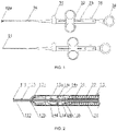
- a multifunctional high-frequency electrosurgical knife in this embodiment comprises a treatment part 10, a sheath part 20, and an operating part 30.
- the treatment part 10 comprises an electrode 11, a clip having a first clamping element 12a and a second clamping element 12b, a first pin shaft 13a, a second pin shaft 13b, a third pin shaft 13c, a fourth pin shaft 13d, a first jaw arm 14a, a second jaw arm 14b, a third jaw arm 14c, and a fourth jaw arm 14d.
- the first jaw arm 14a and the third jaw arm 14c are movably connected by the third pin shaft 13c
- the second jaw arm 14b and the fourth jaw arm 14d are movably connected by the fourth pin shaft 13d
- the first jaw arm 14a and the third jaw arm 14c may also be movably connected in the form of a hook structure 16a
- the second jaw arm 14b and the fourth jaw arm 14d may also be movably connected in the form of a hook structure 16b.
- the first jaw arm 14a and the second jaw arm 14b are movably connected by the second pin shaft 13b.
- the third jaw arm 14c and the fourth jaw arm 14d are movably connected to the tails of the first clamping element 12a and the second clamping element 12b by means of the first pin shaft 13a.
- the first pin shaft 13a is fixedly connected to the distal end of the hollow pull rod 22, and the second pin shaft 13b is movably connected to the distal end of the hollow pull rod 22, so that the hollow pull rod 22 can be pulled to protrude or withdraw the clip component.
- the first clamping element 12a and the second clamping element 12b intersect in a cross shape.
- the clip movably connected by the first pin shaft 13a can be opened or closed.
- the first clamping element 12a and the second clamping element 12b intersect in a cross shape, in the opened state.
- the first clamping element 12a and the second clamping element 12b are symmetrically shaped, so as to form a clip portion of the clip component for performing hemostasis of tissue.
- the first clamping element 12a and the second clamping element 12b may be covered with a coating film or ceramic material serving as an insulator.
- the electrode 11 is passed from the distal end through the hollow pull rod 22 and connected to an operating wire at the proximal end.
- the electrode 11 may comprise a hollow tubular portion 111 extending in an axial direction and a protrusion 112 at the distal end, or the electrode 11 may have only the hollow tubular portion 111 extending in the axial direction without the protrusion 112.
- the distal end of the electrode 11 extends outwardly in a direction perpendicular to the axis of the hollow tubular portion 111 by a length greater than the radius of the cross section of the hollow tubular portion 111 of the electrode, and the outwardly extending portion forms a protrusion 112 at the distal end of the electrode 11.
- the protrusion 112 has a cross section distributed (arranged) circumferentially, and the protrusion 112 is in the shape of a hemisphere.
- the protrusion 112 has a cross section distributed (arranged) circumferentially, and the protrusion 112 is in the shape of a sphere.
- the protrusion 112 has a cross section distributed (arranged) circumferentially, and the protrusion 112 is in a cylindrical shape.
- the protrusion 112 has a cross section distributed (arranged) in a triangular shape, and the protrusion 112 is in the shape of a triangular prism.
- the protrusion 112 has a cross section distributed (arranged) in a Y shape, and the protrusion 112 is Y-shaped.
- the electrode 11 may have only the hollow tubular portion 111 extending in the axial direction.
- the sheath part 20 comprises a fixed base 21, a hollow pull rod 22, a spring tube 23, an insulating outer tube 24, a locking member 15, and a limit block 17.
- the hollow pull rod 22 may be a hollow pull rod allowing the electrode 11 to pass through.
- the first pin shaft 13a is fixedly connected to the distal end of the hollow pull rod 22.
- the third jaw arm 14c and the fourth jaw arm 14d are movably connected to the tails of the first clamping element 12a and the second clamping element 12b by means of the first pin shaft 13a, and fixed to the hollow pull rod 22.
- the second pin shaft 13b is movably connected to the distal end of the hollow pull rod 22.
- the first jaw arm 14a and the second jaw arm 14b are movably connected to each other by means of the second pin shaft 13b, and movably fixed to the hollow pull rod 22.
- the hollow pull rod 22 can be pulled to enable the clip component to be protruded or withdrawn.
- the outer surface of the distal end of the hollow pull rod 22 is covered with the fixed base 21.
- the fixed base 21 may be connected to the distal end of the spring tube 23.
- the spring tube 23 can increase the flexibility and bendability of the multifunctional high-frequency electrosurgical knife.
- the insulating outer tube 24 has a lumen extending along the axis of the sheath part 20, in which the hollow pull rod 22 is movable freely.
- the locking member 15 is provided on the outer surface of the hollow tubular portion 111.
- the locking member 15 is block-shaped, ring-shaped, or tubular, wherein the block-shaped locking member may consist of a set of locking blocks spaced apart from each other.
- the limit block 17 is provided on the outer wall of the hollow tubular portion 111 of the electrode. The limit block 17 will be locked by the first pin shaft 13a to control the maximum distance by which the electrode 11 is protruded toward the front end, thereby controlling the protruded length of the electrode 11.
- the limit block 17 is block-shaped or ring-shaped.
- the operating part 30 is provided at the proximal end of the sheath part 20, which can push out or retract the electrode 11 and the clip component relative to the front end of the sheath part 20, and can provide a lumen through which a liquid is injected.
- the operating part 30 comprises a high-frequency connector 31, a slider 32, a core rod 33, a thumb ring 34, and a liquid inlet 35.
- the thumb ring 34 at the proximal end is connected to the electrode 11 via an operating wire, so as to control the protruding and withdrawal of the electrode 11.
- the high-frequency connector 31 may be connected to the electrode 11 via a wire, to supply the electrode 11 with a high-frequency current.
- the electrode 11 extends distally from its proximal end through the interior of the proximal end of the hollow pull rod 22.
- the slider 32 is connected to the proximal end of the hollow pull rod 22, and the slider 32 is movable back and forth along the core rod 33, so as to drive the hollow pull rod 22 to move, for protruding or retracting the clip component.
- the hollow pull rod 22 drives the first clamping element 12a and the second clamping element 12b to be moved distally and gradually opened to intersect in a cross shape.
- the hollow pull rod 22 drives the first clamping element 12a and the second clamping element 12b to be contracted into the insulating outer tube 24.
- the spring tube 23 and the electrode 11, serving as a driving part are components for torque transmission, so that double drive is formed inside the sheath part 20.
- the spring tube 23 increases the twisting force for the driving part.
- FIGS. 6A-6D illustrate an operation procedure of the multifunctional high-frequency electrosurgical knife in the present disclosure.
- the multifunctional high-frequency electrosurgical knife of the present disclosure is inserted to the vicinity of the lesioned tissue 40 through a channel of an endoscope.
- the electrode 11 is kept in the retracted state, the protrusion 112 of the electrode is closely attached to the first clamping element 12a and the second clamping element 12b, and the first clamping element 12a and the second clamping element 12b are contracted in the insulating outer tube 24.
- the electrode 11 After the multifunctional high-frequency electrosurgical knife reaches the lesioned tissue 40, the electrode 11 is still kept in the retracted state, and the high-frequency connector 31 of the multifunctional high-frequency electrosurgical knife of the present disclosure is connected to an external high-frequency generator, wherein the high-frequency generator includes, but is not limited to, CONMED 60-8200-230, ERBE VIO300S, 300D, etc.
- the high-frequency generator includes, but is not limited to, CONMED 60-8200-230, ERBE VIO300S, 300D, etc.
- the thumb ring 34 of the multifunctional high-frequency electrosurgical knife of the present disclosure is pushed to move forward, so that the electrode 11 is protruded.
- the electrode 11 is placed at a marked point and inserted into the submucosa of the lesioned tissue 40, and normal saline or indigo carmine is injected into the lesioned tissue 40 through the liquid inlet 35 so that the tissue is elevated.
- FIGS. 6C-6D after the lesioned tissue is elevated, a high-frequency current is applied again to the electrode, while the tissue is cut by the electrode 11 in a direction shown in FIG. 6C .
- the application of the high-frequency current is stopped, and the slider 32 is pushed forward to drive the hollow pull rod 22 to move forward, so that the clip component is opened, and the first clamping element 12a and the second clamping element 12b are opened to intersect in a cross shape.
- the thumb ring 34 is retracted backward to withdraw the electrode 11, so that the opened first clamping element 12a and second clamping element 12b can be used as a hemostatic forceps for electrocoagulation and hemostasis.
- the clip component is rotatable freely to conveniently and accurately grasp a bleeding point.
- the thumb ring may be in a shape of circle, square, oval, or the like.
- the multifunctional high-frequency electrosurgical knife according to the present disclosure has both an electrode and a clip component and thus can achieve the integrated functions of liquid injection, cutting, and hemostasis, so that there is no need to frequently change instruments during a surgical procedure, thereby greatly shortening the surgery time and improving the safety of surgery.
- the multifunctional high-frequency electrosurgical knife according to the present disclosure has an electrode made of a metal material with a hollow tubular portion, and the hollow portion forms a liquid channel, so that a liquid can pass through the hollow tubular portion of the electrode and can be submucosally injected for elevating mucosal tissue, or can also be used for cleaning a bleeding site.
- the multifunctional high-frequency electrosurgical knife according to the present disclosure has a first clamping element and a second clamping element that can be freely closed and opened, and a torsional force from the spring tube is transmitted to the clip component so that the clip component is freely rotatable to conveniently and accurately grasp a bleeding point.
- the multifunctional high-frequency electrosurgical knife according to the present disclosure has a locking member and a limit block on the hollow tubular portion of the electrode, so that free positioning can be achieved, and the electrode can be selectively protruded at different lengths according to actual conditions.
Claims (15)
- Couteau électrochirurgical à haute fréquence multifonction, comprenant :une partie de traitement (10), une partie gaine (20), et une partie d'actionnement (30),dans lequel la partie de traitement (10) est située à une extrémité distale du couteau électrochirurgical à haute fréquence multifonction et comprend: une électrode (11), configurée pour couper un tissu et injecter un liquide, dans lequel l'électrode (11) peut être extraite ou rétractée par rapport à une extrémité distale de la partie gaine (20) et l'électrode (11) a une portion tubulaire creuse (111) s'étendant dans une direction axiale ; et un composant pince, configuré pour réaliser l'hémostase d'un tissu, dans lequel le composant pince peut être extrait ou rétracté par rapport à l'extrémité distale de la partie gaine (20) et le composant pince comprend un premier élément de serrage (12a), un second élément de serrage (12b), et un premier axe de goupille (13a) par lequel le premier élément de serrage (12a) et le second élément de serrage (12b) sont reliés, dans lequel le composant pince peut être ouvert et fermé par le premier axe de goupille (13a) qui est entraîné ;la partie gaine (20) est située à une extrémité proximale de la partie de traitement (10) et comprend : une tige de traction creuse (22), dans lequel l'électrode (11) peut s'étendre de manière distale à partir de son extrémité proximale à travers un intérieur d'une extrémité proximale de la tige de traction creuse (22), la tige de traction creuse (22) est reliée au premier élément de serrage (12a) et au second élément de serrage (12b) au moyen du premier axe de goupille (13a), et la tige de traction creuse (22) sert à entraîner le composant pince pour qu'il soit extrait ou rétracté par rapport à l'extrémité distale de la partie gaine (20) ; et un tube extérieur isolant (24), ayant une lumière s'étendant le long d'un axe de la partie gaine (20), dans lequel la tige de traction creuse (22) et le composant pince sont reçus ; etla partie d'actionnement (30) est située à une extrémité proximale de la partie gaine (20) et comprend : un connecteur haute fréquence (31), connecté à l'électrode (11) par l'intermédiaire d'un fil ; un composant, entraînant l'électrode (11) pour qu'elle se déplace au moyen d'un fil d'actionnement ; un organe, entraînant la tige de traction creuse (22) pour qu'elle se déplace ; et une entrée de liquide (35), permettant à un liquide de s'écouler vers la portion tubulaire creuse (111) de l'électrode (11).
- Couteau électrochirurgical à haute fréquence multifonction selon la revendication 1, dans lequel une extrémité distale de l'électrode (11) s'étend vers l'extérieur dans une direction perpendiculaire à un axe de la portion tubulaire creuse (111) sur une longueur plus grande qu'un rayon d'une coupe transversale de la portion tubulaire creuse (111) de l'électrode (11), et une portion s'étendant vers l'extérieur crée une saillie (112) à l'extrémité distale de l'électrode (11).
- Couteau électrochirurgical à haute fréquence multifonction selon la revendication 2, dans lequel la saillie (112) est en forme d'hémisphère, de sphère ou de prisme triangulaire, ou a une forme cylindrique ou une forme de Y.
- Couteau électrochirurgical à haute fréquence multifonction selon l'une quelconque des revendications 1 à 3, dans lequel la partie de traitement (10) comprend en outre un deuxième axe de goupille (13b), un troisième axe de goupille (13c), un quatrième axe de goupille (13d), un premier bras de mâchoire (14a), un deuxième bras de mâchoire (14b), un troisième bras de mâchoire (14c), et un quatrième bras de mâchoire (14d), dans lequel la tige de traction creuse (22) est reliée de manière mobile au troisième bras de mâchoire (14c) et au quatrième bras de mâchoire (14d) au moyen du premier axe de goupille (13a), le troisième bras de mâchoire (14c) et le premier bras de mâchoire (14a) sont reliés de manière mobile par le troisième axe de goupille (13c), le quatrième bras de mâchoire (14d) et le deuxième bras de mâchoire (14b) sont reliés de manière mobile par le quatrième axe de goupille (13d), et le premier bras de mâchoire (14a) et le deuxième bras de mâchoire (14b) sont reliés de manière mobile à la tige de traction creuse (22) au moyen du deuxième axe de goupille (13b).
- Couteau électrochirurgical à haute fréquence multifonction selon la revendication 4, dans lequel le premier bras de mâchoire (14a) et le troisième bras de mâchoire (14c), sous une forme de structure de crochet (16a), sont reliés de manière mobile, et le deuxième bras de mâchoire (14b) et le quatrième bras de mâchoire (14d), sous une forme de structure de crochet (16b), sont reliés de manière mobile.
- Couteau électrochirurgical à haute fréquence multifonction selon l'une quelconque des revendications 1 à 5, dans lequel la partie gaine (20) comprend en outre un tube à ressort (23), qui recouvre une couche extérieure de la tige de traction creuse (22).
- Couteau électrochirurgical à haute fréquence multifonction selon la revendication 6, dans lequel une surface extérieure d'une extrémité distale de la tige de traction creuse (22) est recouverte d'une base fixe (21), dans lequel la base fixe (21) est reliée à une extrémité distale du tube à ressort (23).
- Couteau électrochirurgical à haute fréquence multifonction selon la revendication 1 ou 4, dans lequel lorsque le composant pince est dans un état ouvert, le premier élément de serrage (12a) et le second élément de serrage (12b) se croisent en une forme de croix, et le premier élément de serrage (12a) et le second élément de serrage (12b) sont formés symétriquement, de façon à créer une portion de pince du composant pince.
- Couteau électrochirurgical à haute fréquence multifonction selon l'une quelconque des revendications 1 à 8, dans lequel le premier élément de serrage (12a) et le second élément de serrage (12b) sont revêtus d'un film de revêtement ou d'un matériau céramique.
- Couteau électrochirurgical à haute fréquence multifonction selon l'une quelconque des revendications 1 à 9, dans lequel un organe de verrouillage (15) est prévu sur une surface extérieure de la portion tubulaire creuse (111) de l'électrode (11), et un bloc de limitation (17) est prévu sur une paroi extérieure de la portion tubulaire creuse (111), dans lequel une distance maximale sur laquelle l'électrode (11) fait saillie de manière distale est commandée par la coopération du bloc de limitation (17) avec le premier axe de goupille (13a), et une distance minimale sur laquelle l'électrode (11) fait saillie de manière distale est commandée par la coopération de l'organe de verrouillage (15), du premier élément de serrage (12a), et du second élément de serrage (12b).
- Couteau électrochirurgical à haute fréquence multifonction selon la revendication 10, dans lequel l'organe de verrouillage (15) est en forme de bloc, en forme d'anneau, ou tubulaire.
- Couteau électrochirurgical à haute fréquence multifonction selon la revendication 10 ou 11, dans lequel le bloc de limitation (17) est en forme de bloc ou en forme d'anneau.
- Couteau électrochirurgical à haute fréquence multifonction selon l'une quelconque des revendications 1 à 12, dans lequel la partie d'actionnement (30) comprend en outre une tige centrale (33), qui s'étend le long d'une direction axiale du couteau électrochirurgical à haute fréquence, et une extrémité distale de la tige centrale (33) est reliée au tube extérieur isolant (24).
- Couteau électrochirurgical à haute fréquence multifonction selon la revendication 13, comprenant en outre un curseur (32), dans lequel le curseur (32) peut glisser en va-et-vient le long de la tige centrale (33), de façon à amener à faire saillie ou à rétracter le composant pince.
- Couteau électrochirurgical à haute fréquence multifonction selon l'une quelconque des revendications 1 à 14, dans lequel le composant, entraînant l'électrode (11) pour qu'elle se déplace, est un anneau pour pouce (34) prévu à une extrémité proximale de la partie d'actionnement (30), dans lequel l'anneau pour pouce (34) peut glisser en va-et-vient le long de la tige centrale (33), de façon à amener à faire saillie ou à rétracter l'électrode (11).
Applications Claiming Priority (2)
| Application Number | Priority Date | Filing Date | Title |
|---|---|---|---|
| CN201810366219.1A CN108523985B (zh) | 2018-04-23 | 一种多功能高频电切开刀 | |
| PCT/CN2019/083463 WO2019206042A1 (fr) | 2018-04-23 | 2019-04-19 | Couteau électrique à haute fréquence multifonction |
Publications (3)
| Publication Number | Publication Date |
|---|---|
| EP3785654A1 EP3785654A1 (fr) | 2021-03-03 |
| EP3785654A4 EP3785654A4 (fr) | 2021-06-30 |
| EP3785654B1 true EP3785654B1 (fr) | 2022-05-11 |
Family
ID=63479279
Family Applications (1)
| Application Number | Title | Priority Date | Filing Date |
|---|---|---|---|
| EP19791969.9A Active EP3785654B1 (fr) | 2018-04-23 | 2019-04-19 | Couteau électrique à haute fréquence multifonction |
Country Status (8)
| Country | Link |
|---|---|
| US (1) | US20210077179A1 (fr) |
| EP (1) | EP3785654B1 (fr) |
| JP (1) | JP7064024B2 (fr) |
| KR (1) | KR20210011910A (fr) |
| AU (1) | AU2019260152B2 (fr) |
| BR (1) | BR112020021605A2 (fr) |
| CA (1) | CA3097932C (fr) |
| WO (1) | WO2019206042A1 (fr) |
Families Citing this family (3)
| Publication number | Priority date | Publication date | Assignee | Title |
|---|---|---|---|---|
| CN116761561A (zh) | 2021-01-25 | 2023-09-15 | 奥林巴斯医疗株式会社 | 处置器具 |
| CN113712662B (zh) * | 2021-09-07 | 2022-04-08 | 南昌华安众辉健康科技有限公司 | 一种快装电凝钩及其装配方法 |
| CN113813042B (zh) * | 2021-10-22 | 2023-12-05 | 杭州维纳安可医疗科技有限责任公司 | 电极针及电极装置 |
Family Cites Families (18)
| Publication number | Priority date | Publication date | Assignee | Title |
|---|---|---|---|---|
| US5820630A (en) * | 1996-10-22 | 1998-10-13 | Annex Medical, Inc. | Medical forceps jaw assembly |
| JP2000245740A (ja) | 1999-03-03 | 2000-09-12 | Fuji Photo Optical Co Ltd | 内視鏡用処置具 |
| US6190386B1 (en) * | 1999-03-09 | 2001-02-20 | Everest Medical Corporation | Electrosurgical forceps with needle electrodes |
| JP2001095812A (ja) | 1999-09-29 | 2001-04-10 | Olympus Optical Co Ltd | 切除用高周波処置具 |
| WO2007118608A1 (fr) | 2006-04-11 | 2007-10-25 | Erbe Elektromedizin Gmbh | Instrument chirurgical multifonctions endoscopique |
| US20100217151A1 (en) * | 2007-07-11 | 2010-08-26 | Zach Gostout | Methods and Systems for Performing Submucosal Medical Procedures |
| US20100185196A1 (en) | 2009-01-21 | 2010-07-22 | Satomi Sakao | Medical treatment apparatus, treatment instrument and treatment method for living tissue using energy |
| EP2526884B1 (fr) | 2010-01-22 | 2018-07-11 | Olympus Corporation | Dispositif de traitement |
| US8926609B2 (en) | 2011-11-08 | 2015-01-06 | Olympus Medical Systems Corp. | Treatment device and treatment method |
| WO2014042039A1 (fr) * | 2012-09-12 | 2014-03-20 | オリンパスメディカルシステムズ株式会社 | Couteau à haute fréquence |
| CN103110457B (zh) * | 2013-01-16 | 2015-04-01 | 王实 | 一种黏膜分离刀 |
| WO2015053365A1 (fr) | 2013-10-09 | 2015-04-16 | オリンパスメディカルシステムズ株式会社 | Instrument de traitement haute-fréquence pour endoscope |
| KR101656944B1 (ko) * | 2013-10-16 | 2016-09-19 | 국립암센터 | 내시경용 주사장치 |
| CN205054424U (zh) * | 2015-06-30 | 2016-03-02 | 复旦大学附属中山医院 | 一种经内镜可粘膜下注射的剥离切开刀 |
| US20190374242A1 (en) * | 2015-09-11 | 2019-12-12 | Katya Surgical Ltd | Multi-functional laparoscopic surgical apparatuses and applications thereof |
| CN105434038B (zh) * | 2015-12-15 | 2018-07-06 | 安瑞医疗器械(杭州)有限公司 | 一种内窥镜用多功能高频刀具 |
| JP6655398B2 (ja) * | 2016-01-13 | 2020-02-26 | Hoya株式会社 | 内視鏡用高周波処置具 |
| CN107343815A (zh) * | 2016-05-06 | 2017-11-14 | 徐�明 | 一种多功能复合式高频电刀 |
-
2019
- 2019-04-19 CA CA3097932A patent/CA3097932C/fr active Active
- 2019-04-19 AU AU2019260152A patent/AU2019260152B2/en active Active
- 2019-04-19 WO PCT/CN2019/083463 patent/WO2019206042A1/fr unknown
- 2019-04-19 BR BR112020021605-4A patent/BR112020021605A2/pt unknown
- 2019-04-19 EP EP19791969.9A patent/EP3785654B1/fr active Active
- 2019-04-19 KR KR1020207029757A patent/KR20210011910A/ko not_active Application Discontinuation
- 2019-04-19 JP JP2020570623A patent/JP7064024B2/ja active Active
- 2019-04-19 US US17/048,240 patent/US20210077179A1/en active Pending
Also Published As
| Publication number | Publication date |
|---|---|
| AU2019260152A1 (en) | 2020-11-12 |
| CN108523985A (zh) | 2018-09-14 |
| JP2021516597A (ja) | 2021-07-08 |
| AU2019260152B2 (en) | 2021-12-16 |
| WO2019206042A1 (fr) | 2019-10-31 |
| JP7064024B2 (ja) | 2022-05-09 |
| KR20210011910A (ko) | 2021-02-02 |
| US20210077179A1 (en) | 2021-03-18 |
| BR112020021605A2 (pt) | 2021-01-26 |
| EP3785654A1 (fr) | 2021-03-03 |
| CA3097932A1 (fr) | 2019-10-31 |
| CA3097932C (fr) | 2023-06-20 |
| EP3785654A4 (fr) | 2021-06-30 |
Similar Documents
| Publication | Publication Date | Title |
|---|---|---|
| CA3090198C (fr) | Couteau electrochirurgical a haute frequence bipolaire a injection en double canal | |
| US9421063B2 (en) | Endoscopic devices and related methods of use | |
| JP4366077B2 (ja) | 操縦可能な括約筋切開器具並びにカニューレ挿入、乳頭切開及び括約筋切開方法 | |
| US6296639B1 (en) | Apparatuses and methods for interstitial tissue removal | |
| JP2002511302A (ja) | 電気焼灼器カテーテル | |
| US20050065483A1 (en) | Medical instrument for fluid injection and related method | |
| EP3785654B1 (fr) | Couteau électrique à haute fréquence multifonction | |
| JP3235996U (ja) | 医療用接続装置 | |
| KR102336100B1 (ko) | 복수의 처치구 병용이 가능한 의료용 토출 기구 | |
| US10548626B2 (en) | Endoscopic tissue manipulation tool | |
| US20210100668A1 (en) | Thermopuncture stent implantation device | |
| CN108523985B (zh) | 一种多功能高频电切开刀 | |
| CN209107567U (zh) | 一种多功能高频电切开刀 | |
| CN215018125U (zh) | 一种圈套器和切开刀 | |
| KR102234752B1 (ko) | 내시경 점막하 박리 절제술을 위한 가위형 나이프 | |
| WO2022225648A1 (fr) | Dispositifs pour réaliser une chirurgie intraoculaire et leurs procédés d'utilisation |
Legal Events
| Date | Code | Title | Description |
|---|---|---|---|
| STAA | Information on the status of an ep patent application or granted ep patent |
Free format text: STATUS: THE INTERNATIONAL PUBLICATION HAS BEEN MADE |
|
| STAA | Information on the status of an ep patent application or granted ep patent |
Free format text: STATUS: THE INTERNATIONAL PUBLICATION HAS BEEN MADE |
|
| PUAI | Public reference made under article 153(3) epc to a published international application that has entered the european phase |
Free format text: ORIGINAL CODE: 0009012 |
|
| STAA | Information on the status of an ep patent application or granted ep patent |
Free format text: STATUS: REQUEST FOR EXAMINATION WAS MADE |
|
| 17P | Request for examination filed |
Effective date: 20201029 |
|
| AK | Designated contracting states |
Kind code of ref document: A1 Designated state(s): AL AT BE BG CH CY CZ DE DK EE ES FI FR GB GR HR HU IE IS IT LI LT LU LV MC MK MT NL NO PL PT RO RS SE SI SK SM TR |
|
| AX | Request for extension of the european patent |
Extension state: BA ME |
|
| REG | Reference to a national code |
Ref country code: HK Ref legal event code: DE Ref document number: 40037515 Country of ref document: HK |
|
| A4 | Supplementary search report drawn up and despatched |
Effective date: 20210528 |
|
| RIC1 | Information provided on ipc code assigned before grant |
Ipc: A61B 18/12 20060101AFI20210521BHEP Ipc: A61B 18/14 20060101ALI20210521BHEP Ipc: A61B 18/00 20060101ALN20210521BHEP Ipc: A61B 17/29 20060101ALN20210521BHEP Ipc: A61B 18/08 20060101ALN20210521BHEP Ipc: A61B 17/00 20060101ALN20210521BHEP |
|
| DAV | Request for validation of the european patent (deleted) | ||
| DAX | Request for extension of the european patent (deleted) | ||
| GRAP | Despatch of communication of intention to grant a patent |
Free format text: ORIGINAL CODE: EPIDOSNIGR1 |
|
| STAA | Information on the status of an ep patent application or granted ep patent |
Free format text: STATUS: GRANT OF PATENT IS INTENDED |
|
| RIC1 | Information provided on ipc code assigned before grant |
Ipc: A61B 17/00 20060101ALN20211108BHEP Ipc: A61B 18/08 20060101ALN20211108BHEP Ipc: A61B 17/29 20060101ALN20211108BHEP Ipc: A61B 18/00 20060101ALN20211108BHEP Ipc: A61B 18/14 20060101ALI20211108BHEP Ipc: A61B 18/12 20060101AFI20211108BHEP |
|
| RIC1 | Information provided on ipc code assigned before grant |
Ipc: A61B 17/00 20060101ALN20211117BHEP Ipc: A61B 18/08 20060101ALN20211117BHEP Ipc: A61B 17/29 20060101ALN20211117BHEP Ipc: A61B 18/00 20060101ALN20211117BHEP Ipc: A61B 18/14 20060101ALI20211117BHEP Ipc: A61B 18/12 20060101AFI20211117BHEP |
|
| INTG | Intention to grant announced |
Effective date: 20211202 |
|
| GRAS | Grant fee paid |
Free format text: ORIGINAL CODE: EPIDOSNIGR3 |
|
| GRAA | (expected) grant |
Free format text: ORIGINAL CODE: 0009210 |
|
| STAA | Information on the status of an ep patent application or granted ep patent |
Free format text: STATUS: THE PATENT HAS BEEN GRANTED |
|
| AK | Designated contracting states |
Kind code of ref document: B1 Designated state(s): AL AT BE BG CH CY CZ DE DK EE ES FI FR GB GR HR HU IE IS IT LI LT LU LV MC MK MT NL NO PL PT RO RS SE SI SK SM TR |
|
| REG | Reference to a national code |
Ref country code: GB Ref legal event code: FG4D |
|
| REG | Reference to a national code |
Ref country code: CH Ref legal event code: EP |
|
| REG | Reference to a national code |
Ref country code: AT Ref legal event code: REF Ref document number: 1490746 Country of ref document: AT Kind code of ref document: T Effective date: 20220515 |
|
| REG | Reference to a national code |
Ref country code: DE Ref legal event code: R096 Ref document number: 602019014965 Country of ref document: DE |
|
| REG | Reference to a national code |
Ref country code: IE Ref legal event code: FG4D |
|
| REG | Reference to a national code |
Ref country code: LT Ref legal event code: MG9D |
|
| REG | Reference to a national code |
Ref country code: NL Ref legal event code: MP Effective date: 20220511 |
|
| REG | Reference to a national code |
Ref country code: AT Ref legal event code: MK05 Ref document number: 1490746 Country of ref document: AT Kind code of ref document: T Effective date: 20220511 |
|
| PG25 | Lapsed in a contracting state [announced via postgrant information from national office to epo] |
Ref country code: SE Free format text: LAPSE BECAUSE OF FAILURE TO SUBMIT A TRANSLATION OF THE DESCRIPTION OR TO PAY THE FEE WITHIN THE PRESCRIBED TIME-LIMIT Effective date: 20220511 Ref country code: PT Free format text: LAPSE BECAUSE OF FAILURE TO SUBMIT A TRANSLATION OF THE DESCRIPTION OR TO PAY THE FEE WITHIN THE PRESCRIBED TIME-LIMIT Effective date: 20220912 Ref country code: NO Free format text: LAPSE BECAUSE OF FAILURE TO SUBMIT A TRANSLATION OF THE DESCRIPTION OR TO PAY THE FEE WITHIN THE PRESCRIBED TIME-LIMIT Effective date: 20220811 Ref country code: NL Free format text: LAPSE BECAUSE OF FAILURE TO SUBMIT A TRANSLATION OF THE DESCRIPTION OR TO PAY THE FEE WITHIN THE PRESCRIBED TIME-LIMIT Effective date: 20220511 Ref country code: LT Free format text: LAPSE BECAUSE OF FAILURE TO SUBMIT A TRANSLATION OF THE DESCRIPTION OR TO PAY THE FEE WITHIN THE PRESCRIBED TIME-LIMIT Effective date: 20220511 Ref country code: HR Free format text: LAPSE BECAUSE OF FAILURE TO SUBMIT A TRANSLATION OF THE DESCRIPTION OR TO PAY THE FEE WITHIN THE PRESCRIBED TIME-LIMIT Effective date: 20220511 Ref country code: GR Free format text: LAPSE BECAUSE OF FAILURE TO SUBMIT A TRANSLATION OF THE DESCRIPTION OR TO PAY THE FEE WITHIN THE PRESCRIBED TIME-LIMIT Effective date: 20220812 Ref country code: FI Free format text: LAPSE BECAUSE OF FAILURE TO SUBMIT A TRANSLATION OF THE DESCRIPTION OR TO PAY THE FEE WITHIN THE PRESCRIBED TIME-LIMIT Effective date: 20220511 Ref country code: BG Free format text: LAPSE BECAUSE OF FAILURE TO SUBMIT A TRANSLATION OF THE DESCRIPTION OR TO PAY THE FEE WITHIN THE PRESCRIBED TIME-LIMIT Effective date: 20220811 Ref country code: AT Free format text: LAPSE BECAUSE OF FAILURE TO SUBMIT A TRANSLATION OF THE DESCRIPTION OR TO PAY THE FEE WITHIN THE PRESCRIBED TIME-LIMIT Effective date: 20220511 |
|
| PG25 | Lapsed in a contracting state [announced via postgrant information from national office to epo] |
Ref country code: RS Free format text: LAPSE BECAUSE OF FAILURE TO SUBMIT A TRANSLATION OF THE DESCRIPTION OR TO PAY THE FEE WITHIN THE PRESCRIBED TIME-LIMIT Effective date: 20220511 Ref country code: PL Free format text: LAPSE BECAUSE OF FAILURE TO SUBMIT A TRANSLATION OF THE DESCRIPTION OR TO PAY THE FEE WITHIN THE PRESCRIBED TIME-LIMIT Effective date: 20220511 Ref country code: LV Free format text: LAPSE BECAUSE OF FAILURE TO SUBMIT A TRANSLATION OF THE DESCRIPTION OR TO PAY THE FEE WITHIN THE PRESCRIBED TIME-LIMIT Effective date: 20220511 Ref country code: IS Free format text: LAPSE BECAUSE OF FAILURE TO SUBMIT A TRANSLATION OF THE DESCRIPTION OR TO PAY THE FEE WITHIN THE PRESCRIBED TIME-LIMIT Effective date: 20220911 |
|
| PG25 | Lapsed in a contracting state [announced via postgrant information from national office to epo] |
Ref country code: SM Free format text: LAPSE BECAUSE OF FAILURE TO SUBMIT A TRANSLATION OF THE DESCRIPTION OR TO PAY THE FEE WITHIN THE PRESCRIBED TIME-LIMIT Effective date: 20220511 Ref country code: SK Free format text: LAPSE BECAUSE OF FAILURE TO SUBMIT A TRANSLATION OF THE DESCRIPTION OR TO PAY THE FEE WITHIN THE PRESCRIBED TIME-LIMIT Effective date: 20220511 Ref country code: RO Free format text: LAPSE BECAUSE OF FAILURE TO SUBMIT A TRANSLATION OF THE DESCRIPTION OR TO PAY THE FEE WITHIN THE PRESCRIBED TIME-LIMIT Effective date: 20220511 Ref country code: ES Free format text: LAPSE BECAUSE OF FAILURE TO SUBMIT A TRANSLATION OF THE DESCRIPTION OR TO PAY THE FEE WITHIN THE PRESCRIBED TIME-LIMIT Effective date: 20220511 Ref country code: EE Free format text: LAPSE BECAUSE OF FAILURE TO SUBMIT A TRANSLATION OF THE DESCRIPTION OR TO PAY THE FEE WITHIN THE PRESCRIBED TIME-LIMIT Effective date: 20220511 Ref country code: DK Free format text: LAPSE BECAUSE OF FAILURE TO SUBMIT A TRANSLATION OF THE DESCRIPTION OR TO PAY THE FEE WITHIN THE PRESCRIBED TIME-LIMIT Effective date: 20220511 Ref country code: CZ Free format text: LAPSE BECAUSE OF FAILURE TO SUBMIT A TRANSLATION OF THE DESCRIPTION OR TO PAY THE FEE WITHIN THE PRESCRIBED TIME-LIMIT Effective date: 20220511 |
|
| REG | Reference to a national code |
Ref country code: DE Ref legal event code: R097 Ref document number: 602019014965 Country of ref document: DE |
|
| PLBE | No opposition filed within time limit |
Free format text: ORIGINAL CODE: 0009261 |
|
| STAA | Information on the status of an ep patent application or granted ep patent |
Free format text: STATUS: NO OPPOSITION FILED WITHIN TIME LIMIT |
|
| PG25 | Lapsed in a contracting state [announced via postgrant information from national office to epo] |
Ref country code: AL Free format text: LAPSE BECAUSE OF FAILURE TO SUBMIT A TRANSLATION OF THE DESCRIPTION OR TO PAY THE FEE WITHIN THE PRESCRIBED TIME-LIMIT Effective date: 20220511 |
|
| 26N | No opposition filed |
Effective date: 20230214 |
|
| PG25 | Lapsed in a contracting state [announced via postgrant information from national office to epo] |
Ref country code: SI Free format text: LAPSE BECAUSE OF FAILURE TO SUBMIT A TRANSLATION OF THE DESCRIPTION OR TO PAY THE FEE WITHIN THE PRESCRIBED TIME-LIMIT Effective date: 20220511 |
|
| PGFP | Annual fee paid to national office [announced via postgrant information from national office to epo] |
Ref country code: FR Payment date: 20230406 Year of fee payment: 5 Ref country code: DE Payment date: 20230418 Year of fee payment: 5 |
|
| PGFP | Annual fee paid to national office [announced via postgrant information from national office to epo] |
Ref country code: GB Payment date: 20230403 Year of fee payment: 5 |
|
| REG | Reference to a national code |
Ref country code: CH Ref legal event code: PL |
|
| PG25 | Lapsed in a contracting state [announced via postgrant information from national office to epo] |
Ref country code: LU Free format text: LAPSE BECAUSE OF NON-PAYMENT OF DUE FEES Effective date: 20230419 |
|
| REG | Reference to a national code |
Ref country code: BE Ref legal event code: MM Effective date: 20230430 |
|
| PG25 | Lapsed in a contracting state [announced via postgrant information from national office to epo] |
Ref country code: MC Free format text: LAPSE BECAUSE OF FAILURE TO SUBMIT A TRANSLATION OF THE DESCRIPTION OR TO PAY THE FEE WITHIN THE PRESCRIBED TIME-LIMIT Effective date: 20220511 |
|
| PG25 | Lapsed in a contracting state [announced via postgrant information from national office to epo] |
Ref country code: MC Free format text: LAPSE BECAUSE OF FAILURE TO SUBMIT A TRANSLATION OF THE DESCRIPTION OR TO PAY THE FEE WITHIN THE PRESCRIBED TIME-LIMIT Effective date: 20220511 Ref country code: LI Free format text: LAPSE BECAUSE OF NON-PAYMENT OF DUE FEES Effective date: 20230430 Ref country code: IT Free format text: LAPSE BECAUSE OF FAILURE TO SUBMIT A TRANSLATION OF THE DESCRIPTION OR TO PAY THE FEE WITHIN THE PRESCRIBED TIME-LIMIT Effective date: 20220511 Ref country code: CH Free format text: LAPSE BECAUSE OF NON-PAYMENT OF DUE FEES Effective date: 20230430 |
|
| REG | Reference to a national code |
Ref country code: IE Ref legal event code: MM4A |
|
| PG25 | Lapsed in a contracting state [announced via postgrant information from national office to epo] |
Ref country code: BE Free format text: LAPSE BECAUSE OF NON-PAYMENT OF DUE FEES Effective date: 20230430 |
|
| PG25 | Lapsed in a contracting state [announced via postgrant information from national office to epo] |
Ref country code: IE Free format text: LAPSE BECAUSE OF NON-PAYMENT OF DUE FEES Effective date: 20230419 |