EP3784874B1 - Improving access into subsea structures - Google Patents
Improving access into subsea structures Download PDFInfo
- Publication number
- EP3784874B1 EP3784874B1 EP19725283.6A EP19725283A EP3784874B1 EP 3784874 B1 EP3784874 B1 EP 3784874B1 EP 19725283 A EP19725283 A EP 19725283A EP 3784874 B1 EP3784874 B1 EP 3784874B1
- Authority
- EP
- European Patent Office
- Prior art keywords
- housing
- closure
- operating member
- access opening
- wall
- Prior art date
- Legal status (The legal status is an assumption and is not a legal conclusion. Google has not performed a legal analysis and makes no representation as to the accuracy of the status listed.)
- Active
Links
Images



Classifications
-
- E—FIXED CONSTRUCTIONS
- E21—EARTH OR ROCK DRILLING; MINING
- E21B—EARTH OR ROCK DRILLING; OBTAINING OIL, GAS, WATER, SOLUBLE OR MELTABLE MATERIALS OR A SLURRY OF MINERALS FROM WELLS
- E21B33/00—Sealing or packing boreholes or wells
- E21B33/02—Surface sealing or packing
- E21B33/03—Well heads; Setting-up thereof
- E21B33/035—Well heads; Setting-up thereof specially adapted for underwater installations
- E21B33/037—Protective housings therefor
-
- B—PERFORMING OPERATIONS; TRANSPORTING
- B63—SHIPS OR OTHER WATERBORNE VESSELS; RELATED EQUIPMENT
- B63C—LAUNCHING, HAULING-OUT, OR DRY-DOCKING OF VESSELS; LIFE-SAVING IN WATER; EQUIPMENT FOR DWELLING OR WORKING UNDER WATER; MEANS FOR SALVAGING OR SEARCHING FOR UNDERWATER OBJECTS
- B63C11/00—Equipment for dwelling or working underwater; Means for searching for underwater objects
- B63C11/52—Tools specially adapted for working underwater, not otherwise provided for
-
- B—PERFORMING OPERATIONS; TRANSPORTING
- B63—SHIPS OR OTHER WATERBORNE VESSELS; RELATED EQUIPMENT
- B63G—OFFENSIVE OR DEFENSIVE ARRANGEMENTS ON VESSELS; MINE-LAYING; MINE-SWEEPING; SUBMARINES; AIRCRAFT CARRIERS
- B63G8/00—Underwater vessels, e.g. submarines; Equipment specially adapted therefor
- B63G8/001—Underwater vessels adapted for special purposes, e.g. unmanned underwater vessels; Equipment specially adapted therefor, e.g. docking stations
-
- E—FIXED CONSTRUCTIONS
- E02—HYDRAULIC ENGINEERING; FOUNDATIONS; SOIL SHIFTING
- E02D—FOUNDATIONS; EXCAVATIONS; EMBANKMENTS; UNDERGROUND OR UNDERWATER STRUCTURES
- E02D29/00—Independent underground or underwater structures; Retaining walls
-
- E—FIXED CONSTRUCTIONS
- E02—HYDRAULIC ENGINEERING; FOUNDATIONS; SOIL SHIFTING
- E02D—FOUNDATIONS; EXCAVATIONS; EMBANKMENTS; UNDERGROUND OR UNDERWATER STRUCTURES
- E02D29/00—Independent underground or underwater structures; Retaining walls
- E02D29/06—Constructions, or methods of constructing, in water
-
- E—FIXED CONSTRUCTIONS
- E21—EARTH OR ROCK DRILLING; MINING
- E21B—EARTH OR ROCK DRILLING; OBTAINING OIL, GAS, WATER, SOLUBLE OR MELTABLE MATERIALS OR A SLURRY OF MINERALS FROM WELLS
- E21B41/00—Equipment or details not covered by groups E21B15/00 - E21B40/00
- E21B41/08—Underwater guide bases, e.g. drilling templates; Levelling thereof
-
- B—PERFORMING OPERATIONS; TRANSPORTING
- B63—SHIPS OR OTHER WATERBORNE VESSELS; RELATED EQUIPMENT
- B63G—OFFENSIVE OR DEFENSIVE ARRANGEMENTS ON VESSELS; MINE-LAYING; MINE-SWEEPING; SUBMARINES; AIRCRAFT CARRIERS
- B63G8/00—Underwater vessels, e.g. submarines; Equipment specially adapted therefor
- B63G8/001—Underwater vessels adapted for special purposes, e.g. unmanned underwater vessels; Equipment specially adapted therefor, e.g. docking stations
- B63G2008/002—Underwater vessels adapted for special purposes, e.g. unmanned underwater vessels; Equipment specially adapted therefor, e.g. docking stations unmanned
Definitions
- This invention relates to the challenges of providing and improving access into subsea structures as are used, for example, in the subsea oil and gas industry.
- subsea oil and gas pipelines connect to, or to incorporate, subsea structures that are dedicated to particular functions required in a subsea installation.
- some such structures may serve as templates for drilling a subsea well and for housing wellheads and related equipment such as Christmas trees.
- Other such structures may serve as subsea processing centres for conditioning production fluids that flow from a well.
- Subsea structures designed for exploitation of hydrocarbons contain various items of equipment and accessories that enable flow management of fluids, such as connectors, valves, ports and auxiliary control panels. Such structures also contain small-diameter piping, for example two-inch (5.1cm) lines for injection of chemicals. Some subsea structures also carry replaceable modules, for example a pump module or a control system module.
- a subsea structure It is often desirable for a subsea structure to protect the equipment, accessories or modules that it carries. For example, protection may be required against objects that could be dropped from vessels on the surface above. This requires a subsea structure to have a roof, cover or frame that extends over and at least partially encloses the equipment, accessories or modules beneath. Protection is especially required against overtrawling, which is a particular risk when producing hydrocarbons in relatively shallow waters such as the North Sea.
- WO 03/044316 and GB 2410758 illustrate the conventional solution of adding a protective upper frame to a subsea structure.
- Tubular members of the frame carry lattice, mesh or solid panels that bridge gaps between those members to cover the more fragile items of equipment and accessories carried by the structure.
- the frame or the panels may be made of steel or of composites such as glass-fibre reinforced plastics (GRP).
- UUVs unmanned underwater vehicles
- ROVs remotely-operated vehicles
- UUV intervention requires openings in the protective frame of a subsea structure that are large enough for a UUV to gain the necessary access without becoming snagged. It is also preferable for any closures such as covers or panels over those openings to be movable or removable by a UUV alone without assistance from a surface vessel.
- a protective frame on top of a subsea structure often supports closures such as hatches or doors so that the contents of the structure can be accessed when required.
- Hatches may comprise panels that are articulated to the frame by hinges, for example as shown in WO 2010/115712 .
- a handle allows the hatch to be lifted open by a surface vessel or by an ROV.
- Another articulated hatch arrangement is disclosed in WO 2012/095485 .
- GB 1602001 shows how a hatch may be lifted from the surface using cables or wires.
- WO 02/075103 discloses another type of hinged cover.
- the design and manufacture of this cover is more complex and its articulation may be prone to jamming.
- WO 2017/191106 discloses another pivoting articulation arrangement for a hatch.
- hatches and other movable or removable closures described above are not optimal for subsea use because features such as handles or hooks protruding from them may be snagged by trawls.
- the invention provides a protective subsea housing for protecting an equipment space enclosed by the housing.
- the housing comprises: an access opening in a wall of the housing for providing access to the equipment space by an unmanned underwater vehicle (UUV); a closure that is movable by translation, or by rotation relative to an axis transverse to the wall, to open and close the access opening; and an operating member, positioned outside the equipment space, that is engageable by and movable by the UUV to move the closure.
- UUV unmanned underwater vehicle
- the closure may be movable substantially parallel to the wall.
- the wall may be planar, in which case the closure may be movable in a parallel plane.
- the closure may be positioned on an inner side of the wall, within the equipment space.
- the closure may be positioned on an outer side of the wall.
- the closure may be substantially surrounded by a ridge that protrudes from the outer side of the wall.
- the closure may be rotatable about a pivot that is fixed to the wall beside the access opening.
- the closure may comprise a part-circular panel that can be pivoted across or away from the access opening, the panel having a curved edge whose axis of curvature coincides with the pivot.
- the operating member may be mounted on the housing and may be spaced from the access opening and the closure.
- the operating member is movable relative to the housing to operate a drive mechanism that acts on the closure.
- the operating member may be a rotatable coupling.
- the operating member may have at least one female or male formation arranged for engagement with a torque tool of a UUV.
- the drive mechanism suitably comprises a drive shaft to which the operating member is connected.
- the drive shaft may comprise at least one gear that engages the closure to move the closure as the drive shaft turns.
- the gear may be a sprocket that engages a series of slots in the closure, or a worm that engages a series of teeth on the closure.
- the drive shaft may intersect an edge of the closure.
- the drive shaft may intersect a curved edge of the closure tangentially.
- the drive shaft is positioned on an outer side of the wall, it is preferably substantially concealed within a tubular channel for protection against overtrawling. Such a channel may taper away from the wall.
- the drive mechanism may comprises at least one nut fixed to the closure and at least one threaded rod engaged with the nut. When the rod is turned about its longitudinal axis, the nut and the closure move along the turning rod.
- the operating member may be connected to the drive mechanism by a generator and motor combination. There may be at least one geared connection between the operating member and the drive mechanism.
- the closure may comprise two or more articulated sections. Articulation between successive sections may be about an axis transverse to a direction of opening or closing movement.
- the operating member may be a handle that is mounted on, and movable with, the closure.
- the access opening may be surrounded by a frame to which the closure is mounted.
- the frame may be movable relative to the housing, for example by pivoting, to open a larger opening that provides alternative access to the equipment space.
- the invention provides a sliding hatch system for subsea protection structures that enables the hatch to be opened by an ROV without extra assistance.
- the opening mechanism may comprise rotating parts and may be actuated either directly by the ROV, or indirectly. Preferably, direct actuation is achieved by coupling a torque tool of the ROV to a shaft of the mechanism.
- the invention removes the need to suspend wires from the surface to lift covers or hatches. This is particularly useful for remote fields that operate with the support of a local UUV but without continuous support from a surface vessel.
- Embodiments of the invention provide a hatch for a subsea protection frame, wherein the hatch can slide along a wall of the protection frame between an open configuration and a closed configuration.
- the hatch may, for example, slide inside the frame.
- the hatch may slide in translation and/or in rotation.
- the hatch may comprise at least one panel. Two or more panels may be articulated in a direction transverse to the motion of the hatch.
- Sliding movement of the hatch may be effected by a drive mechanism.
- the drive mechanism may comprise at least one shaft that is rotated by coupling directly or indirectly to a tool of an ROV.
- the shaft may extend perpendicularly to the direction of translation.
- the shaft may, for example, wind cables, wires or ropes that connect to at least one panel in the direction of translation.
- the shaft may rotate a gear that couples or meshes with slots arranged successively in the direction of translation.
- At least one shaft of the drive mechanism may be disposed tangentially to a direction of rotation of a shutter that is rotated by turning the shaft.
- the hatch may comprise teeth at least partially on its circumference that are coupled to a gear in mechanical relation with the shaft.
- the torque tool of an ROV may actuate a generator that electrically powers a motor to rotate the shaft of the drive mechanism.
- the parts of a frame carrying elements of a hatch mechanism and a hatch may be mounted on a structure that can be opened as a bigger hatch, by hinging or lifting.
- FIGS 1 to 7 and 10a to 11b of the drawings show part of a protective housing 10 of a subsea structure that is designed for protection against overtrawling.
- the structure and the housing are designed to be placed in a fixed subsea location, typically resting on the seabed.
- the complete housing 10 defines a substantially continuous enclosure for equipment, accessories and modules supported by the structure. Such items have been omitted from the drawings for clarity.
- FIG. 1 and 2 these drawings illustrate a first embodiment of the invention.
- an access opening 12 is provided in a flat side or end wall 14 of the housing 10 that is inclined to the vertical so as to intersect a horizontal top wall 16 at an obtuse angle.
- One or more access openings 12 may instead, or additionally, be provided in the top wall 16 of the housing 10 as shown in Figures 3 to 7 and 10a to 11b .
- a shutter 18, shown closed in Figure 1 and open in Figure 2 serves as a screen, barrier or closure that is retractable and extensible across the access opening 12 to open and close the access opening 12.
- the shutter 18 runs along parallel rails 20, one each side of the access opening 12 as shown in Figure 2 , which guide the movement of the shutter 18 relative to the access opening 12.
- the shutter 18 translates relative to the access opening 12. In doing so, the shutter 18 moves substantially parallel to the side or end wall 14 of the housing 10 that surrounds the access opening 12. Thus, in this example, the shutter 18 moves in a plane that is similarly inclined to the vertical.
- the shutter 18 moves up and down to open and close the access opening 12, specifically moving up to close the access opening 12 and down to open the access opening 12.
- this arrangement could be reversed or the shutter 18 could instead move laterally from side to side.
- Movement and positioning of the shutter 18 is driven and determined by a drive mechanism 22.
- the drive mechanism 22 comprises threaded rods 24, one each side of the access opening 12, that suspend the shutter 18 between them on nuts 26 fixed to the inner side of the shutter 18.
- the threaded rods 24 extend substantially parallel to the side or end wall 14 of the housing 10 that surrounds the access opening 12.
- the threaded rods 24 are driven, in turn, by a common drive shaft 28 that is positioned above, and spans the width of, the access opening 12.
- each threaded rod 24 is connected to the drive shaft 28 by a respective gearbox 30 that may, for example, contain bevel gears to turn the drive through 90°. Consequently, the threaded rods 24 turn around their respective longitudinal axes when the drive shaft 28 is turned about its longitudinal axis.
- the housing 10 supports an externally-accessible, recessed coupling 32 that serves as an operating member for driving movement of the shutter 18.
- the coupling 32 is shaped to engage a torque tool held by, or integrated with, an ROV.
- the coupling 32 has a recess or socket that is arranged to receive the rotary head of a torque tool, as can be seen in Figures 8 and 9 .
- the coupling it would be possible for the coupling to have other female or male engagement formations.
- the drive shaft 28 extends laterally beyond the access opening 12 to the coupling 32, which may, for example, be on a side wall 34 of the housing 10 spaced from the access opening 12.
- the coupling 32 is rigidly attached to the drive shaft 28 so that turning the coupling 32 turns the drive shaft 28 and therefore opens or closes the shutter 18.
- the coupling 32 may be regarded as part of the drive mechanism 22 or as acting on the drive mechanism 22. It will be appreciated that the coupling 32 need not be attached directly to the drive shaft 28; for example, an intermediate shaft, a gear system and/or an electrical link could link the coupling 32 to the drive shaft 28. Two such options will be described later with reference to Figures 8 and 9 .
- An ROV hovering beside the housing 10 can couple a torque tool with the coupling 32 and can then activate the torque tool to turn the coupling 32 and thereby to turn the drive shaft 28 to open or close the shutter 18.
- the ROV can open the shutter 18 to gain access to the interior of the housing 10 through the access opening 12 to perform tasks on equipment, accessories or modules within the structure.
- the ROV can leave the housing 10 through the access opening 12 and then can couple its torque tool with the coupling 32 to close the shutter 18.
- the shutter 18 comprises a series of articulated sections or slats 36 so that the shutter 18 can bend about the successive axes of articulation.
- the shutter 18 can bend to follow the contours of the housing 10 below or adjacent to the access opening 12.
- FIGs 3 to 7 and 10a to 11b show further embodiments of the invention in the context of an access opening 12 in the top wall 16 of the housing 10.
- FIGs 1 and 2 show further embodiments of the invention in the context of an access opening 12 in the top wall 16 of the housing 10.
- these embodiments are suitable for use with access openings provided instead, or additionally, in the side or end wall 14 of the housing 10 as shown in Figures 1 and 2 .
- FIGS 3 and 4 show a second embodiment of the invention in which a closure 38 is a rigid panel that translates by sliding across the access opening 12, in this case beneath the top wall 16 of the housing 10.
- the closure 38 is shown closed in Figure 3 and partially open in Figure 4 .
- the closure 38 may run along parallel rails 20 under the top wall 16, one each side of the access opening 12 like the rails 20 shown in Figure 1 .
- the drive mechanism comprises a drive shaft 28 that extends parallel to the top wall 16 beside the access opening 12.
- the drive shaft 28 extends orthogonally with respect to the direction of movement of the closure 38.
- the drive shaft 28 is concealed within an upwardly-tapering tubular channel 40 on top of the top wall 16.
- the channel 40 protects the drive shaft 28 against snagging in the event of overtrawling.
- the channel 40 is open to at least one end.
- at least one end of the drive shaft 28 terminates in an externally-accessible, recessed coupling 32 for engaging a torque tool of an ROV to turn the drive shaft 28.
- the drive shaft 28 carries one or more toothed wheels, in this example a pair of sprockets 42 that are spaced longitudinally from each other along the drive shaft 28.
- the sprockets 42 align with, and protrude downwardly through, complementary apertures 44 in the top wall 16.
- the teeth of the sprockets 42 engage with respective rows of slots 46 in the closure 38, aligned with the apertures 44 in the top wall 16.
- the rows of slots 46 are parallel to each other and to the direction of movement of the closure 38. In each row, the slots 46 are parallel to each other and extend orthogonally with respect to the direction of movement of the closure 38.
- the third embodiment shown in Figures 5 and 6 shows one way in which a closure 48 can move, relative to an access opening 12 of the housing 10, by rotation rather than translation.
- the closure 48 is circular and planar and turns about its central axis to open and close the access opening 12.
- the central axis of the closure 48 coincides with a pivot 50 that defines an upright pivot axis.
- the pivot 50 protrudes upwardly from the top wall 16 of the housing 10 and mounts the closure 48 to the top wall 16. More generally, the pivot axis is transverse to, or extends through, the top wall 16.
- the closure 48 comprises a circular gear ring 52 that has an array of teeth on its radially outer side.
- the closure 48 further comprises a part-circular infill panel 54 within the gear ring, through which the pivot 50 extends.
- the infill panel 54 is defined by a chord that extends across the radially inner side of the gear ring 52, close to the pivot 50, to close just over half of the circular area that is encircled by the gear ring 52.
- the infill panel 54 of the closure 48 is shaped and dimensioned to cover a part-circular access opening 12 in the top wall 16 of the housing 10.
- the access opening 12 is partially bounded by a chord and has a part-circular boundary that is curved about the pivot axis.
- the pivot 50 is positioned on the top wall 16 close to the chord of the access opening 12.
- the access opening 12 occupies just under half of the circular area that is encircled by the gear ring 52 of the closure 48.
- the access opening 12 is encircled by a ridge 56 on the radially outer side of the closure 48.
- the ridge 56 protects the closure 48 against snagging when overtrawling.
- the drive mechanism comprises a drive shaft 28 that extends parallel to the top wall 16 of the housing 10 beside the access opening 12.
- the drive shaft 28 is concealed within an upwardly-tapering tubular channel 40 on top of the top wall 16.
- the channel 40 is open to at least one end to provide access to an externally-accessible coupling 32 of the drive shaft 28 for engagement by a torque tool of an ROV.
- the drive shaft 28 substantially intersects the periphery of the closure 48.
- the drive shaft 28 extends substantially tangentially with respect to the periphery of the closure 48.
- the drive shaft 28 carries a spiral worm 58 that engages the teeth on the circular gear ring 52 of the closure 48.
- Figure 7 illustrates a variant of the third embodiment in which most features are unchanged and therefore have like numerals.
- the drive mechanism including the drive shaft 28 is omitted, as is the toothed gear ring 52 of the closure 48 shown in Figures 5 and 6 .
- the closure 60 shown in Figure 7 has one or more handles 62 on the infill panel 54 that serve as operating members.
- the closure 60 further comprises a plain untoothed ring 64, which could itself be omitted.
- the closure 60 is turned to open or close the access opening 12 by applying an appropriate force to the or each handle 62 about the pivot 50.
- a UUV such as an ROV, or a diver, can apply the necessary force.
- FIGS 8 and 9 show, schematically, that the coupling 32 need not be attached directly to the drive shaft 28.
- the coupling 32 is connected to the drive shaft 28 via a gearbox 66.
- the gearbox 66 may, for example, comprise meshed pinions of different sizes.
- the gearbox 66 implements a desired gearing ratio and torque multiplication between the input from a torque tool and the output to the drive shaft 28.
- the coupling 32 is connected to a generator 68 that generates electrical energy when the coupling 32 is spun by a torque tool.
- Wires 70 or other conductors convey the electrical energy from the generator 68 to a motor 72 that turns the drive shaft 28.
- the absence of a rigid link between the coupling 32 and the drive shaft 28 provides greater freedom in positioning the coupling 32 relative to the drive shaft 28.
- a gearbox could be interposed between the coupling 32 and the generator 68 or between the motor 72 and the drive shaft 28 to implement a desired gearing ratio if required.
- a fourth embodiment of the invention mounts a movable closure 74 in a surrounding frame 76, which frame 76 is mounted movably or removably in the top wall 16 of a protective housing 10.
- a drive mechanism like that shown in the preceding embodiments could be employed to move the closure 74 relative to the frame 76 but has been omitted from Figures 10a to 11b for clarity.
- the frame 76 contains a primary access opening 12 that communicates with the interior of the housing 10.
- the primary access opening 12 can be opened or closed by moving the closure 74 relative to the frame 76, without moving the frame 76 relative to the housing 10.
- the closure 74 operates like a wicket gate.
- the frame 76 may itself be moved relative to the housing 10, or removed from the housing 10, to open a secondary, but larger, access opening 78 in the housing 10.
- the frame 76 is provided with handles 80 to be lifted by an ROV or by winch wires suspended from a surface vessel.
- the ability to move or to remove the frame 76 may be useful in two scenarios: firstly to provide auxiliary access if the closure 74 ever jams or fails; and secondly to allow access into the housing 10 for the installation or removal of large accessories or modules.
- a latch arrangement may be provided to ensure that the frame 76 remains fixed relative to the housing 10 until the latch is deliberately released.
- an ROV-removable locking pin may act between the frame 76 and the surrounding housing 10.
- the closure 74 is exemplified in Figures 10a to 11b as a shutter of articulated slats 36 like that of the first embodiment shown in Figures 1 and 2 .
- other closure arrangements like those of the other preceding embodiments could be employed.
- frame 76 Whilst the frame 76 is shown in Figures 10a to 11b as being pivotably mounted to the housing 10 by hinges 82, the frame 76 could be moved in other ways relative to the housing 10, such as by translation or rotation.
- UUV other than an ROV, such as an autonomous underwater vehicle (AUV), or indeed for a diver
- UUV autonomous underwater vehicle
- a torque tool with an external coupling to open or close a shutter or other closure.
Landscapes
- Engineering & Computer Science (AREA)
- Life Sciences & Earth Sciences (AREA)
- Mining & Mineral Resources (AREA)
- Geology (AREA)
- General Life Sciences & Earth Sciences (AREA)
- Environmental & Geological Engineering (AREA)
- Mechanical Engineering (AREA)
- Geochemistry & Mineralogy (AREA)
- Physics & Mathematics (AREA)
- Fluid Mechanics (AREA)
- Paleontology (AREA)
- Civil Engineering (AREA)
- General Engineering & Computer Science (AREA)
- Structural Engineering (AREA)
- Aviation & Aerospace Engineering (AREA)
- Ocean & Marine Engineering (AREA)
- Power-Operated Mechanisms For Wings (AREA)
Description
- This invention relates to the challenges of providing and improving access into subsea structures as are used, for example, in the subsea oil and gas industry.
- It is well known for subsea oil and gas pipelines to connect to, or to incorporate, subsea structures that are dedicated to particular functions required in a subsea installation. For example, some such structures may serve as templates for drilling a subsea well and for housing wellheads and related equipment such as Christmas trees. Other such structures may serve as subsea processing centres for conditioning production fluids that flow from a well.
- Subsea structures designed for exploitation of hydrocarbons contain various items of equipment and accessories that enable flow management of fluids, such as connectors, valves, ports and auxiliary control panels. Such structures also contain small-diameter piping, for example two-inch (5.1cm) lines for injection of chemicals. Some subsea structures also carry replaceable modules, for example a pump module or a control system module.
- It is often desirable for a subsea structure to protect the equipment, accessories or modules that it carries. For example, protection may be required against objects that could be dropped from vessels on the surface above. This requires a subsea structure to have a roof, cover or frame that extends over and at least partially encloses the equipment, accessories or modules beneath. Protection is especially required against overtrawling, which is a particular risk when producing hydrocarbons in relatively shallow waters such as the North Sea.
- Protection against overtrawling requires a subsea structure to be shaped to avoid snagging fishing nets. Thus, such a structure has a generally smooth outline with rounded edges and inclined faces. Commonly, the structure will have substantially flat side or end faces that are inclined to the vertical so as to intersect the plane of a horizontal top surface at an obtuse angle. Consequently the structure tapers or narrows upwardly from the seabed, which directs trawled fishing nets to ride over the structure rather than becoming snagged and entangled.
-
WO 03/044316 GB 2410758 - There is also an ongoing need to access equipment, accessories or modules carried by a subsea structure. This may be for various operational purposes such as installation, maintenance, replenishment, replacement and control. Consequently, the requirement for a subsea structure to maintain effective protection of its contents must be balanced against the need to ensure ready access to those contents whenever required.
- In this respect, it is often necessary to access the interior of a subsea structure using unmanned underwater vehicles (UUVs) such as remotely-operated vehicles (ROVs). In principle, divers could perform similar tasks if the water is shallow enough but in practice, it is preferable to use a UUV to improve safety, especially in an overhead environment.
- UUV intervention requires openings in the protective frame of a subsea structure that are large enough for a UUV to gain the necessary access without becoming snagged. It is also preferable for any closures such as covers or panels over those openings to be movable or removable by a UUV alone without assistance from a surface vessel.
- A protective frame on top of a subsea structure often supports closures such as hatches or doors so that the contents of the structure can be accessed when required. Hatches may comprise panels that are articulated to the frame by hinges, for example as shown in
WO 2010/115712 . A handle allows the hatch to be lifted open by a surface vessel or by an ROV. Another articulated hatch arrangement is disclosed inWO 2012/095485 . -
GB 1602001 -
WO 02/075103 -
WO 2017/191106 discloses another pivoting articulation arrangement for a hatch. - In
WO 2016/085352 , an entire cover cap has to be removed from a subsea structure for accessing a wellhead. - NO 336 853 B1 a hatchet located on the top surface of a frame rotates around a pivoting point to allow top access to a subsea structure
-
US 4 273 472 A a protective cap is lowered into position to close off a protection housing by guidelines. - The hatches and other movable or removable closures described above are not optimal for subsea use because features such as handles or hooks protruding from them may be snagged by trawls.
- Also, wide hatches that must be moved to perform subsea operations involving large accessories or modules may require extra lifting provisions, such as winch wires and/or additional buoyancy, because a UUV alone cannot handle their weight.
- Against this background, the invention provides a protective subsea housing for protecting an equipment space enclosed by the housing. The housing comprises: an access opening in a wall of the housing for providing access to the equipment space by an unmanned underwater vehicle (UUV); a closure that is movable by translation, or by rotation relative to an axis transverse to the wall, to open and close the access opening; and an operating member, positioned outside the equipment space, that is engageable by and movable by the UUV to move the closure.
- The closure may be movable substantially parallel to the wall. For example, the wall may be planar, in which case the closure may be movable in a parallel plane.
- The closure may be positioned on an inner side of the wall, within the equipment space. Alternatively, the closure may be positioned on an outer side of the wall. In that case, for protection against overtrawling, the closure may be substantially surrounded by a ridge that protrudes from the outer side of the wall.
- The closure may be rotatable about a pivot that is fixed to the wall beside the access opening. For example, the closure may comprise a part-circular panel that can be pivoted across or away from the access opening, the panel having a curved edge whose axis of curvature coincides with the pivot.
- Conveniently, the operating member may be mounted on the housing and may be spaced from the access opening and the closure.
- The operating member is movable relative to the housing to operate a drive mechanism that acts on the closure. For example, the operating member may be a rotatable coupling. The operating member may have at least one female or male formation arranged for engagement with a torque tool of a UUV.
- The drive mechanism suitably comprises a drive shaft to which the operating member is connected. The drive shaft may comprise at least one gear that engages the closure to move the closure as the drive shaft turns. The gear may be a sprocket that engages a series of slots in the closure, or a worm that engages a series of teeth on the closure.
- The drive shaft may intersect an edge of the closure. For example, where the closure is at least partially circular, the drive shaft may intersect a curved edge of the closure tangentially.
- If the drive shaft is positioned on an outer side of the wall, it is preferably substantially concealed within a tubular channel for protection against overtrawling. Such a channel may taper away from the wall.
- The drive mechanism may comprises at least one nut fixed to the closure and at least one threaded rod engaged with the nut. When the rod is turned about its longitudinal axis, the nut and the closure move along the turning rod.
- The operating member may be connected to the drive mechanism by a generator and motor combination. There may be at least one geared connection between the operating member and the drive mechanism.
- The closure may comprise two or more articulated sections. Articulation between successive sections may be about an axis transverse to a direction of opening or closing movement.
- The operating member may be a handle that is mounted on, and movable with, the closure.
- The access opening may be surrounded by a frame to which the closure is mounted. The frame may be movable relative to the housing, for example by pivoting, to open a larger opening that provides alternative access to the equipment space.
- The invention provides a sliding hatch system for subsea protection structures that enables the hatch to be opened by an ROV without extra assistance. The opening mechanism may comprise rotating parts and may be actuated either directly by the ROV, or indirectly. Preferably, direct actuation is achieved by coupling a torque tool of the ROV to a shaft of the mechanism.
- The invention removes the need to suspend wires from the surface to lift covers or hatches. This is particularly useful for remote fields that operate with the support of a local UUV but without continuous support from a surface vessel.
- Embodiments of the invention provide a hatch for a subsea protection frame, wherein the hatch can slide along a wall of the protection frame between an open configuration and a closed configuration.
- The hatch may, for example, slide inside the frame. The hatch may slide in translation and/or in rotation.
- The hatch may comprise at least one panel. Two or more panels may be articulated in a direction transverse to the motion of the hatch.
- Sliding movement of the hatch may be effected by a drive mechanism. The drive mechanism may comprise at least one shaft that is rotated by coupling directly or indirectly to a tool of an ROV.
- The shaft may extend perpendicularly to the direction of translation. The shaft may, for example, wind cables, wires or ropes that connect to at least one panel in the direction of translation. In another approach, the shaft may rotate a gear that couples or meshes with slots arranged successively in the direction of translation.
- In another arrangement, at least one shaft of the drive mechanism may be disposed tangentially to a direction of rotation of a shutter that is rotated by turning the shaft. For example, the hatch may comprise teeth at least partially on its circumference that are coupled to a gear in mechanical relation with the shaft.
- The torque tool of an ROV may actuate a generator that electrically powers a motor to rotate the shaft of the drive mechanism.
- The parts of a frame carrying elements of a hatch mechanism and a hatch may be mounted on a structure that can be opened as a bigger hatch, by hinging or lifting.
- In order that the invention may be more readily understood, reference will now be made, by way of example, to the accompanying drawings in which:
-
Figure 1 is an external perspective view of a first embodiment of the invention; -
Figure 2 is an internal perspective view of the first embodiment shown inFigure 1 ; -
Figure 3 is an external perspective view of a second embodiment of the invention; -
Figure 4 is an enlarged detail perspective view of the second embodiment shown inFigure 3 ; -
Figure 5 is an external perspective view of a third embodiment of the invention; -
Figure 6 is an enlarged detail perspective view of the third embodiment shown inFigure 5 ; -
Figure 7 is an external perspective view of a variant of the third embodiment; -
Figure 8 is a schematic side view of a drive mechanism comprising a gearbox; -
Figure 9 is a schematic side view of a drive mechanism comprising a generator and motor combination; -
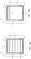
Figures 10a and 10b are top plan views of a fourth embodiment of the invention, showing a hatch closed and partially open within a surrounding frame; and -
Figures 11a and 11b are sectional side views of the frame in closed and open positions while the hatch remains closed within the frame, the longitudinal section ofFigure 11a being taken on line XI-XI ofFigure 10a . - Where possible, like numerals are used in the drawings and in the following description for like features.
-
Figures 1 to 7 and10a to 11b of the drawings show part of aprotective housing 10 of a subsea structure that is designed for protection against overtrawling. The structure and the housing are designed to be placed in a fixed subsea location, typically resting on the seabed. - The
complete housing 10 defines a substantially continuous enclosure for equipment, accessories and modules supported by the structure. Such items have been omitted from the drawings for clarity. - Referring now specifically to
Figures 1 and 2 , these drawings illustrate a first embodiment of the invention. In this example, anaccess opening 12 is provided in a flat side or endwall 14 of thehousing 10 that is inclined to the vertical so as to intersect a horizontaltop wall 16 at an obtuse angle. One ormore access openings 12 may instead, or additionally, be provided in thetop wall 16 of thehousing 10 as shown inFigures 3 to 7 and10a to 11b . - A
shutter 18, shown closed inFigure 1 and open inFigure 2 , serves as a screen, barrier or closure that is retractable and extensible across the access opening 12 to open and close theaccess opening 12. Theshutter 18 runs alongparallel rails 20, one each side of the access opening 12 as shown inFigure 2 , which guide the movement of theshutter 18 relative to theaccess opening 12. - In this example, the
shutter 18 translates relative to theaccess opening 12. In doing so, theshutter 18 moves substantially parallel to the side or endwall 14 of thehousing 10 that surrounds theaccess opening 12. Thus, in this example, theshutter 18 moves in a plane that is similarly inclined to the vertical. - In the example shown in
Figures 1 and 2 , theshutter 18 moves up and down to open and close the access opening 12, specifically moving up to close the access opening 12 and down to open theaccess opening 12. However, this arrangement could be reversed or theshutter 18 could instead move laterally from side to side. - Movement and positioning of the
shutter 18 is driven and determined by adrive mechanism 22. As shown inFigure 2 , thedrive mechanism 22 comprises threadedrods 24, one each side of the access opening 12, that suspend theshutter 18 between them onnuts 26 fixed to the inner side of theshutter 18. The threadedrods 24 extend substantially parallel to the side or endwall 14 of thehousing 10 that surrounds theaccess opening 12. - The threaded
rods 24 are driven, in turn, by acommon drive shaft 28 that is positioned above, and spans the width of, theaccess opening 12. For this purpose, each threadedrod 24 is connected to thedrive shaft 28 by arespective gearbox 30 that may, for example, contain bevel gears to turn the drive through 90°. Consequently, the threadedrods 24 turn around their respective longitudinal axes when thedrive shaft 28 is turned about its longitudinal axis. - As the threaded
rods 24 turn relative to theshutter 18, the nuts 26 fixed to theshutter 18 move up or down along the threadedrods 24 with synchronised movement. Thus, rotation of thedrive shaft 28 in the appropriate angular direction slides theshutter 18 up into the closed position shown inFigure 1 or down into the open position shown inFigure 2 . - The
housing 10 supports an externally-accessible, recessedcoupling 32 that serves as an operating member for driving movement of theshutter 18. For this purpose, thecoupling 32 is shaped to engage a torque tool held by, or integrated with, an ROV. Typically thecoupling 32 has a recess or socket that is arranged to receive the rotary head of a torque tool, as can be seen inFigures 8 and 9 . In principle, it would be possible for the coupling to have other female or male engagement formations. - As can be appreciated from
Figure 2 , thedrive shaft 28 extends laterally beyond the access opening 12 to thecoupling 32, which may, for example, be on aside wall 34 of thehousing 10 spaced from theaccess opening 12. Thecoupling 32 is rigidly attached to thedrive shaft 28 so that turning thecoupling 32 turns thedrive shaft 28 and therefore opens or closes theshutter 18. - Thus, the
coupling 32 may be regarded as part of thedrive mechanism 22 or as acting on thedrive mechanism 22. It will be appreciated that thecoupling 32 need not be attached directly to thedrive shaft 28; for example, an intermediate shaft, a gear system and/or an electrical link could link thecoupling 32 to thedrive shaft 28. Two such options will be described later with reference toFigures 8 and 9 . - An ROV hovering beside the
housing 10 can couple a torque tool with thecoupling 32 and can then activate the torque tool to turn thecoupling 32 and thereby to turn thedrive shaft 28 to open or close theshutter 18. In this way, the ROV can open theshutter 18 to gain access to the interior of thehousing 10 through the access opening 12 to perform tasks on equipment, accessories or modules within the structure. When the tasks are complete, the ROV can leave thehousing 10 through the access opening 12 and then can couple its torque tool with thecoupling 32 to close theshutter 18. - Preferably, as shown, the
shutter 18 comprises a series of articulated sections orslats 36 so that theshutter 18 can bend about the successive axes of articulation. For example, when retracted to open the access opening 12 as shown inFigure 2 , theshutter 18 can bend to follow the contours of thehousing 10 below or adjacent to theaccess opening 12. -
Figures 3 to 7 and10a to 11b show further embodiments of the invention in the context of an access opening 12 in thetop wall 16 of thehousing 10. However, it should be noted that these embodiments are suitable for use with access openings provided instead, or additionally, in the side or endwall 14 of thehousing 10 as shown inFigures 1 and 2 . - Turning next, then, to
Figures 3 and 4 , these drawings show a second embodiment of the invention in which aclosure 38 is a rigid panel that translates by sliding across the access opening 12, in this case beneath thetop wall 16 of thehousing 10. Theclosure 38 is shown closed inFigure 3 and partially open inFigure 4 . - The
closure 38 may run alongparallel rails 20 under thetop wall 16, one each side of the access opening 12 like therails 20 shown inFigure 1 . - In this second embodiment, the drive mechanism comprises a
drive shaft 28 that extends parallel to thetop wall 16 beside theaccess opening 12. Thedrive shaft 28 extends orthogonally with respect to the direction of movement of theclosure 38. - The
drive shaft 28 is concealed within an upwardly-taperingtubular channel 40 on top of thetop wall 16. Thechannel 40 protects thedrive shaft 28 against snagging in the event of overtrawling. Thechannel 40 is open to at least one end. Here, at least one end of thedrive shaft 28 terminates in an externally-accessible, recessedcoupling 32 for engaging a torque tool of an ROV to turn thedrive shaft 28. - As best appreciated in
Figure 4 , thedrive shaft 28 carries one or more toothed wheels, in this example a pair ofsprockets 42 that are spaced longitudinally from each other along thedrive shaft 28. - The
sprockets 42 align with, and protrude downwardly through,complementary apertures 44 in thetop wall 16. Here, the teeth of thesprockets 42 engage with respective rows ofslots 46 in theclosure 38, aligned with theapertures 44 in thetop wall 16. - The rows of
slots 46 are parallel to each other and to the direction of movement of theclosure 38. In each row, theslots 46 are parallel to each other and extend orthogonally with respect to the direction of movement of theclosure 38. - By virtue of the engagement of the
sprockets 42 with the rows ofslots 46, rotation of thedrive shaft 28 about its longitudinal axis, driven by the ROV, is converted into longitudinal movement of theclosure 38. Changing the direction of angular movement of thedrive shaft 28 changes the direction of movement of theclosure 38. - The third embodiment shown in
Figures 5 and 6 shows one way in which aclosure 48 can move, relative to an access opening 12 of thehousing 10, by rotation rather than translation. Here, theclosure 48 is circular and planar and turns about its central axis to open and close theaccess opening 12. The central axis of theclosure 48 coincides with apivot 50 that defines an upright pivot axis. Thepivot 50 protrudes upwardly from thetop wall 16 of thehousing 10 and mounts theclosure 48 to thetop wall 16. More generally, the pivot axis is transverse to, or extends through, thetop wall 16. - In this embodiment, the
closure 48 comprises acircular gear ring 52 that has an array of teeth on its radially outer side. Theclosure 48 further comprises a part-circular infill panel 54 within the gear ring, through which thepivot 50 extends. In this example, theinfill panel 54 is defined by a chord that extends across the radially inner side of thegear ring 52, close to thepivot 50, to close just over half of the circular area that is encircled by thegear ring 52. - The
infill panel 54 of theclosure 48 is shaped and dimensioned to cover a part-circular access opening 12 in thetop wall 16 of thehousing 10. Like theinfill panel 54, the access opening 12 is partially bounded by a chord and has a part-circular boundary that is curved about the pivot axis. Thepivot 50 is positioned on thetop wall 16 close to the chord of theaccess opening 12. Thus, the access opening 12 occupies just under half of the circular area that is encircled by thegear ring 52 of theclosure 48. - The
access opening 12 is encircled by aridge 56 on the radially outer side of theclosure 48. Theridge 56 protects theclosure 48 against snagging when overtrawling. - As in the second embodiment shown in
Figures 3 and 4 , the drive mechanism comprises adrive shaft 28 that extends parallel to thetop wall 16 of thehousing 10 beside theaccess opening 12. Again, thedrive shaft 28 is concealed within an upwardly-taperingtubular channel 40 on top of thetop wall 16. Similarly, thechannel 40 is open to at least one end to provide access to an externally-accessible coupling 32 of thedrive shaft 28 for engagement by a torque tool of an ROV. - In the third embodiment, however, the
drive shaft 28 substantially intersects the periphery of theclosure 48. In this example, thedrive shaft 28 extends substantially tangentially with respect to the periphery of theclosure 48. Thedrive shaft 28 carries aspiral worm 58 that engages the teeth on thecircular gear ring 52 of theclosure 48. - By virtue of the engagement of the
worm 58 with the teeth on thegear ring 52, rotation of thedrive shaft 28 about its longitudinal axis, driven by the ROV, is converted into rotational movement of theclosure 48 about thepivot 50. Changing the direction of angular movement of thedrive shaft 28 changes the direction of angular movement of theclosure 48. -
Figure 7 illustrates a variant of the third embodiment in which most features are unchanged and therefore have like numerals. The main differences here are that the drive mechanism including thedrive shaft 28 is omitted, as is thetoothed gear ring 52 of theclosure 48 shown inFigures 5 and 6 . Instead, theclosure 60 shown inFigure 7 has one ormore handles 62 on theinfill panel 54 that serve as operating members. Theclosure 60 further comprises a plainuntoothed ring 64, which could itself be omitted. Theclosure 60 is turned to open or close the access opening 12 by applying an appropriate force to the or each handle 62 about thepivot 50. A UUV such as an ROV, or a diver, can apply the necessary force. -
Figures 8 and 9 show, schematically, that thecoupling 32 need not be attached directly to thedrive shaft 28. - In
Figure 8 , for example, thecoupling 32 is connected to thedrive shaft 28 via agearbox 66. Thegearbox 66 may, for example, comprise meshed pinions of different sizes. Thegearbox 66 implements a desired gearing ratio and torque multiplication between the input from a torque tool and the output to thedrive shaft 28. - In
Figure 9 , thecoupling 32 is connected to agenerator 68 that generates electrical energy when thecoupling 32 is spun by a torque tool.Wires 70 or other conductors convey the electrical energy from thegenerator 68 to amotor 72 that turns thedrive shaft 28. The absence of a rigid link between thecoupling 32 and thedrive shaft 28 provides greater freedom in positioning thecoupling 32 relative to thedrive shaft 28. - In a variant of the arrangement of
Figure 9 , a gearbox could be interposed between thecoupling 32 and thegenerator 68 or between themotor 72 and thedrive shaft 28 to implement a desired gearing ratio if required. - Turning finally to
Figures 10a to 11b , a fourth embodiment of the invention mounts amovable closure 74 in a surroundingframe 76, whichframe 76 is mounted movably or removably in thetop wall 16 of aprotective housing 10. A drive mechanism like that shown in the preceding embodiments could be employed to move theclosure 74 relative to theframe 76 but has been omitted fromFigures 10a to 11b for clarity. - The
frame 76 contains a primary access opening 12 that communicates with the interior of thehousing 10. The primary access opening 12 can be opened or closed by moving theclosure 74 relative to theframe 76, without moving theframe 76 relative to thehousing 10. Thus, theclosure 74 operates like a wicket gate. - The
frame 76 may itself be moved relative to thehousing 10, or removed from thehousing 10, to open a secondary, but larger, access opening 78 in thehousing 10. For this purpose, theframe 76 is provided withhandles 80 to be lifted by an ROV or by winch wires suspended from a surface vessel. - The ability to move or to remove the
frame 76 may be useful in two scenarios: firstly to provide auxiliary access if theclosure 74 ever jams or fails; and secondly to allow access into thehousing 10 for the installation or removal of large accessories or modules. - A latch arrangement may be provided to ensure that the
frame 76 remains fixed relative to thehousing 10 until the latch is deliberately released. For example, an ROV-removable locking pin may act between theframe 76 and the surroundinghousing 10. - The
closure 74 is exemplified inFigures 10a to 11b as a shutter of articulatedslats 36 like that of the first embodiment shown inFigures 1 and 2 . However, other closure arrangements like those of the other preceding embodiments could be employed. - Whilst the
frame 76 is shown inFigures 10a to 11b as being pivotably mounted to thehousing 10 byhinges 82, theframe 76 could be moved in other ways relative to thehousing 10, such as by translation or rotation. - Many variations are possible within the inventive concept. For example, it would be possible for a UUV other than an ROV, such as an autonomous underwater vehicle (AUV), or indeed for a diver, to couple a torque tool with an external coupling to open or close a shutter or other closure. Also, it is not essential that the same UUV both operates the closure and enters the housing.
Claims (20)
- A protective subsea housing (10) for protecting an equipment space enclosed by the housing (10), the housing (10) comprising an access opening (12) in a wall (14) of the housing (10) for providing access to the equipment space by an unmanned underwater vehicle (UUV), the housing (10) being characterised by:a closure (18, 38, 48) that is movable by translation, or by rotation relative to an axis transverse to the wall (14), to open and close the access opening (12); andan operating member (32), positioned outside the equipment space, that is engageable by and movable by the UUV to move the closure (18, 38, 48), wherein the operating member (32) is movable relative to the housing (10) to operate a drive mechanism (22) that acts on the closure (18, 38, 48).
- The housing (10) of Claim 1, wherein the closure (18, 38, 48) is movable substantially parallel to the wall (14).
- The housing (10) of Claim 2, wherein the wall (14) is planar and the closure (18, 38, 48) is movable in a parallel plane.
- The housing (10) of any preceding claim, wherein the closure (18, 38, 48) is positioned on an inner side of the wall (14), within the equipment space.
- The housing (10) of any of Claims 1 to 3, wherein the closure (18, 38, 48) is positioned on an outer side of the wall (14).
- The housing (10) of Claim 5, wherein the closure (18, 38, 48) is substantially surrounded by a ridge (56) that protrudes from the outer side of the wall (14).
- The housing (10) of any preceding claim, wherein the closure (18, 38, 48) is rotatable about a pivot (50) beside the access opening (12).
- The housing (10) of Claim 7, wherein the closure (18, 38, 48) comprises a part-circular panel (54) that can be pivoted across or away from the access opening (12), the panel (54) having a curved edge whose axis of curvature coincides with the pivot (50).
- The housing (10) of any preceding claim, wherein the operating member (32) is mounted on the housing (10) and is spaced from the access opening (12) and the closure (18, 38, 48).
- The housing (10) of any preceding claim, wherein the operating member (32) is a rotatable coupling.
- The housing (10) of any preceding claim, wherein the operating member (32) has at least one female or male formation arranged for engagement with a UUV torque tool.
- The housing (10) of any preceding claim, wherein the drive mechanism (22) comprises a drive shaft (28) to which the operating member (32) is connected.
- The housing (10) of Claim 12, wherein the drive shaft (28) comprises at least one gear (42, 58) that engages the closure (18, 38, 48) to move the closure (18, 38, 48) as the drive shaft (28) turns.
- The housing (10) of any preceding claim, wherein the drive mechanism (22) comprises at least one nut (26) fixed to the closure (18, 38, 48) and at least one threaded rod (24) engaged with the nut (26) and is arranged to turn the rod (24) so that the nut (26) and the closure (18, 38, 48) move along the turning rod (24).
- The housing (10) of any preceding claim, wherein the operating member (32) is connected to the drive mechanism (22) by a generator and motor combination (68, 72).
- The housing (10) of any preceding claim, further comprising at least one geared connection (66) between the operating member (32) and the drive mechanism (22).
- The housing (10) of any preceding claim, wherein the closure (18, 38, 48) comprises two or more articulated sections.
- The housing (10) of any preceding claim, wherein the operating member (32) is a handle (62) that is mounted on, and movable with, the closure (18, 38, 48).
- The housing (10) of any preceding claim, wherein:the access opening (12) is surrounded by a frame (76) to which the closure (18, 38, 48) is mounted; andthe frame (76) is movable relative to the housing (10) to open a larger opening (78) that provides alternative access to the equipment space.
- The housing (10) of Claim 19, wherein the frame (76) is pivotably mounted to the housing (10) for opening the larger opening (78).
Priority Applications (1)
| Application Number | Priority Date | Filing Date | Title |
|---|---|---|---|
| EP23166227.1A EP4219887B1 (en) | 2018-04-26 | 2019-04-26 | Improving access into subsea structures |
Applications Claiming Priority (2)
| Application Number | Priority Date | Filing Date | Title |
|---|---|---|---|
| GB1806823.9A GB2573144B (en) | 2018-04-26 | 2018-04-26 | A protective subsea housing with a movable closure |
| PCT/EP2019/060754 WO2019207114A1 (en) | 2018-04-26 | 2019-04-26 | Improving access into subsea structures |
Related Child Applications (2)
| Application Number | Title | Priority Date | Filing Date |
|---|---|---|---|
| EP23166227.1A Division EP4219887B1 (en) | 2018-04-26 | 2019-04-26 | Improving access into subsea structures |
| EP23166227.1A Division-Into EP4219887B1 (en) | 2018-04-26 | 2019-04-26 | Improving access into subsea structures |
Publications (2)
| Publication Number | Publication Date |
|---|---|
| EP3784874A1 EP3784874A1 (en) | 2021-03-03 |
| EP3784874B1 true EP3784874B1 (en) | 2023-06-28 |
Family
ID=62495148
Family Applications (2)
| Application Number | Title | Priority Date | Filing Date |
|---|---|---|---|
| EP23166227.1A Active EP4219887B1 (en) | 2018-04-26 | 2019-04-26 | Improving access into subsea structures |
| EP19725283.6A Active EP3784874B1 (en) | 2018-04-26 | 2019-04-26 | Improving access into subsea structures |
Family Applications Before (1)
| Application Number | Title | Priority Date | Filing Date |
|---|---|---|---|
| EP23166227.1A Active EP4219887B1 (en) | 2018-04-26 | 2019-04-26 | Improving access into subsea structures |
Country Status (4)
| Country | Link |
|---|---|
| US (1) | US12031402B2 (en) |
| EP (2) | EP4219887B1 (en) |
| GB (1) | GB2573144B (en) |
| WO (1) | WO2019207114A1 (en) |
Families Citing this family (1)
| Publication number | Priority date | Publication date | Assignee | Title |
|---|---|---|---|---|
| EP4053375B1 (en) | 2021-03-04 | 2024-04-24 | Horisont Energi AS | Subsea template for injecting fluid for long term storage in a subterranean void and method of controlling a subsea template |
Citations (3)
| Publication number | Priority date | Publication date | Assignee | Title |
|---|---|---|---|---|
| US4273472A (en) * | 1978-02-20 | 1981-06-16 | Fmc Corporation | Apparatus for protecting subsea wells |
| WO1990004084A1 (en) * | 1988-10-14 | 1990-04-19 | Den Norske Stats Oljeselskap A.S | Arrangement for protecting components in subsea systems |
| NO336853B1 (en) * | 2014-02-18 | 2015-11-16 | Hallesen Imr Solutions V Helge Thomas Hallesen | Sealing arrangement for an underwater protection device and method using the same |
Family Cites Families (14)
| Publication number | Priority date | Publication date | Assignee | Title |
|---|---|---|---|---|
| GB1180603A (en) | 1966-04-29 | 1970-02-04 | Ass Cargo Gear Ab | Improvements in or relating to Hatch Covers |
| CA2248054C (en) * | 1998-09-23 | 2005-09-06 | Robert Jacques Labelle | Port closure for a tank and method of retrofitting a tank with the same |
| NO20010738A (en) | 2001-02-13 | 2002-02-11 | Abb Offshore Systems As | Weed and procedure for making it |
| NO20015649L (en) * | 2001-11-20 | 2003-05-21 | Abb Offshore Systems As | Protective structure for underwater installations |
| US6615923B1 (en) * | 2002-07-17 | 2003-09-09 | Milford Lay, Jr. | ROV-deployable subsea wellhead protector |
| AU2004216662B2 (en) * | 2003-10-07 | 2006-01-19 | Ky Stockfeeds Pty Ltd | Storage silo or tank closure apparatus |
| US8070009B2 (en) * | 2004-01-23 | 2011-12-06 | Rmc Engineering Co., Inc. | Remotely activated tank hatch system |
| GB0402428D0 (en) * | 2004-02-04 | 2004-03-10 | Subsea 7 Uk | Apparatus and method |
| US20090145905A1 (en) * | 2007-12-06 | 2009-06-11 | Kim Sun Y | Sliding hatch cover with internal seal for pressurized bulk carriers |
| NO329295B1 (en) * | 2009-04-02 | 2010-09-27 | Aker Subsea As | Well frame for protection of subsea well equipment, and method |
| NO20110048A1 (en) | 2011-01-12 | 2012-07-13 | Aker Subsea As | Wiring assembly for seabed valve tree |
| NO333245B1 (en) | 2011-04-07 | 2013-04-15 | Oilfield Technology Group As | Device for operations in an underwater installation |
| GB2532754B (en) | 2014-11-26 | 2020-11-25 | Equinor Energy As | Subsea equipment-protection apparatus |
| NO343186B1 (en) | 2016-05-02 | 2018-11-26 | Fmc Kongsberg Subsea As | Method for installing a hatch to a protective subsea structure, a hinge and an assembly for subsea use. |
-
2018
- 2018-04-26 GB GB1806823.9A patent/GB2573144B/en active Active
-
2019
- 2019-04-26 WO PCT/EP2019/060754 patent/WO2019207114A1/en not_active Ceased
- 2019-04-26 EP EP23166227.1A patent/EP4219887B1/en active Active
- 2019-04-26 US US17/050,820 patent/US12031402B2/en active Active
- 2019-04-26 EP EP19725283.6A patent/EP3784874B1/en active Active
Patent Citations (3)
| Publication number | Priority date | Publication date | Assignee | Title |
|---|---|---|---|---|
| US4273472A (en) * | 1978-02-20 | 1981-06-16 | Fmc Corporation | Apparatus for protecting subsea wells |
| WO1990004084A1 (en) * | 1988-10-14 | 1990-04-19 | Den Norske Stats Oljeselskap A.S | Arrangement for protecting components in subsea systems |
| NO336853B1 (en) * | 2014-02-18 | 2015-11-16 | Hallesen Imr Solutions V Helge Thomas Hallesen | Sealing arrangement for an underwater protection device and method using the same |
Also Published As
| Publication number | Publication date |
|---|---|
| EP4219887A1 (en) | 2023-08-02 |
| GB2573144A (en) | 2019-10-30 |
| WO2019207114A1 (en) | 2019-10-31 |
| GB201806823D0 (en) | 2018-06-13 |
| EP4219887B1 (en) | 2024-02-07 |
| GB2573144B (en) | 2020-07-29 |
| US12031402B2 (en) | 2024-07-09 |
| US20210047875A1 (en) | 2021-02-18 |
| EP3784874A1 (en) | 2021-03-03 |
Similar Documents
| Publication | Publication Date | Title |
|---|---|---|
| CN101954959B (en) | Deepwater semi-submerged drilling platform | |
| US3099316A (en) | Underwater wellhead apparatus and method | |
| CN111649984A (en) | Deep sea sediment sampling device and sampling method thereof | |
| EA022483B1 (en) | Service space for a retractable propulsion device | |
| CN212568021U (en) | Deep sea sediment sampling equipment | |
| EP4219887B1 (en) | Improving access into subsea structures | |
| US3163221A (en) | Underwater manipulator for wells | |
| AU2017325988B2 (en) | Boat gate | |
| NO20141439A1 (en) | A moon pool control device in a marine vessel | |
| CN109802278B (en) | A device for treating broken wires of armored cables | |
| NO344728B1 (en) | Protective subsea housing with an access opening and a movable closure | |
| RU2466902C2 (en) | Anchors handling device | |
| CN106394837A (en) | Submarine pipeline transporting and loading boat | |
| KR101298628B1 (en) | Door module for drive launch and recovery system of vessel or marine structure and operating system of this | |
| KR101422824B1 (en) | The vessel having rotating retractable thruster | |
| CN107804444B (en) | A device for opening and closing doors of a manned submersible | |
| NO342752B1 (en) | Remote operation of subsea protection structures | |
| US6925954B1 (en) | Systems and methods for allowing underwater escape from a submarine | |
| NL2016740B1 (en) | Moon pool for a ship or marine platform and sliding hatch cover there for, and method for lowering and lifting tools and/or instruments. | |
| CN107284626B (en) | A container for submersible deployment and recovery equipment | |
| WO2013028593A2 (en) | Riser-mounted guide assembly for umbilical deployment | |
| KR102237344B1 (en) | Emergency generator for electric enclosed door | |
| KR101498208B1 (en) | Apparatus for maintenance of azimuth thruster | |
| US3954610A (en) | Method and subsurface work chamber for making transparent an underwater cloudy work area | |
| KR101336208B1 (en) | Apparatus for opening and closing a hatch, ship and ocean structure including the same |
Legal Events
| Date | Code | Title | Description |
|---|---|---|---|
| STAA | Information on the status of an ep patent application or granted ep patent |
Free format text: STATUS: UNKNOWN |
|
| STAA | Information on the status of an ep patent application or granted ep patent |
Free format text: STATUS: THE INTERNATIONAL PUBLICATION HAS BEEN MADE |
|
| TPAC | Observations filed by third parties |
Free format text: ORIGINAL CODE: EPIDOSNTIPA |
|
| PUAI | Public reference made under article 153(3) epc to a published international application that has entered the european phase |
Free format text: ORIGINAL CODE: 0009012 |
|
| STAA | Information on the status of an ep patent application or granted ep patent |
Free format text: STATUS: REQUEST FOR EXAMINATION WAS MADE |
|
| 17P | Request for examination filed |
Effective date: 20201102 |
|
| AK | Designated contracting states |
Kind code of ref document: A1 Designated state(s): AL AT BE BG CH CY CZ DE DK EE ES FI FR GB GR HR HU IE IS IT LI LT LU LV MC MK MT NL NO PL PT RO RS SE SI SK SM TR |
|
| AX | Request for extension of the european patent |
Extension state: BA ME |
|
| DAV | Request for validation of the european patent (deleted) | ||
| DAX | Request for extension of the european patent (deleted) | ||
| STAA | Information on the status of an ep patent application or granted ep patent |
Free format text: STATUS: EXAMINATION IS IN PROGRESS |
|
| 17Q | First examination report despatched |
Effective date: 20220504 |
|
| GRAP | Despatch of communication of intention to grant a patent |
Free format text: ORIGINAL CODE: EPIDOSNIGR1 |
|
| STAA | Information on the status of an ep patent application or granted ep patent |
Free format text: STATUS: GRANT OF PATENT IS INTENDED |
|
| INTG | Intention to grant announced |
Effective date: 20230213 |
|
| GRAS | Grant fee paid |
Free format text: ORIGINAL CODE: EPIDOSNIGR3 |
|
| GRAA | (expected) grant |
Free format text: ORIGINAL CODE: 0009210 |
|
| STAA | Information on the status of an ep patent application or granted ep patent |
Free format text: STATUS: THE PATENT HAS BEEN GRANTED |
|
| AK | Designated contracting states |
Kind code of ref document: B1 Designated state(s): AL AT BE BG CH CY CZ DE DK EE ES FI FR GB GR HR HU IE IS IT LI LT LU LV MC MK MT NL NO PL PT RO RS SE SI SK SM TR |
|
| REG | Reference to a national code |
Ref country code: CH Ref legal event code: EP |
|
| P01 | Opt-out of the competence of the unified patent court (upc) registered |
Effective date: 20230526 |
|
| REG | Reference to a national code |
Ref country code: AT Ref legal event code: REF Ref document number: 1582831 Country of ref document: AT Kind code of ref document: T Effective date: 20230715 |
|
| REG | Reference to a national code |
Ref country code: IE Ref legal event code: FG4D |
|
| REG | Reference to a national code |
Ref country code: DE Ref legal event code: R096 Ref document number: 602019031698 Country of ref document: DE |
|
| REG | Reference to a national code |
Ref country code: LT Ref legal event code: MG9D |
|
| REG | Reference to a national code |
Ref country code: NO Ref legal event code: T2 Effective date: 20230628 |
|
| PG25 | Lapsed in a contracting state [announced via postgrant information from national office to epo] |
Ref country code: SE Free format text: LAPSE BECAUSE OF FAILURE TO SUBMIT A TRANSLATION OF THE DESCRIPTION OR TO PAY THE FEE WITHIN THE PRESCRIBED TIME-LIMIT Effective date: 20230628 |
|
| REG | Reference to a national code |
Ref country code: NL Ref legal event code: MP Effective date: 20230628 |
|
| REG | Reference to a national code |
Ref country code: AT Ref legal event code: MK05 Ref document number: 1582831 Country of ref document: AT Kind code of ref document: T Effective date: 20230628 |
|
| PG25 | Lapsed in a contracting state [announced via postgrant information from national office to epo] |
Ref country code: RS Free format text: LAPSE BECAUSE OF FAILURE TO SUBMIT A TRANSLATION OF THE DESCRIPTION OR TO PAY THE FEE WITHIN THE PRESCRIBED TIME-LIMIT Effective date: 20230628 Ref country code: NL Free format text: LAPSE BECAUSE OF FAILURE TO SUBMIT A TRANSLATION OF THE DESCRIPTION OR TO PAY THE FEE WITHIN THE PRESCRIBED TIME-LIMIT Effective date: 20230628 Ref country code: LV Free format text: LAPSE BECAUSE OF FAILURE TO SUBMIT A TRANSLATION OF THE DESCRIPTION OR TO PAY THE FEE WITHIN THE PRESCRIBED TIME-LIMIT Effective date: 20230628 Ref country code: LT Free format text: LAPSE BECAUSE OF FAILURE TO SUBMIT A TRANSLATION OF THE DESCRIPTION OR TO PAY THE FEE WITHIN THE PRESCRIBED TIME-LIMIT Effective date: 20230628 Ref country code: HR Free format text: LAPSE BECAUSE OF FAILURE TO SUBMIT A TRANSLATION OF THE DESCRIPTION OR TO PAY THE FEE WITHIN THE PRESCRIBED TIME-LIMIT Effective date: 20230628 Ref country code: GR Free format text: LAPSE BECAUSE OF FAILURE TO SUBMIT A TRANSLATION OF THE DESCRIPTION OR TO PAY THE FEE WITHIN THE PRESCRIBED TIME-LIMIT Effective date: 20230929 |
|
| PG25 | Lapsed in a contracting state [announced via postgrant information from national office to epo] |
Ref country code: FI Free format text: LAPSE BECAUSE OF FAILURE TO SUBMIT A TRANSLATION OF THE DESCRIPTION OR TO PAY THE FEE WITHIN THE PRESCRIBED TIME-LIMIT Effective date: 20230628 |
|
| PG25 | Lapsed in a contracting state [announced via postgrant information from national office to epo] |
Ref country code: SK Free format text: LAPSE BECAUSE OF FAILURE TO SUBMIT A TRANSLATION OF THE DESCRIPTION OR TO PAY THE FEE WITHIN THE PRESCRIBED TIME-LIMIT Effective date: 20230628 |
|
| PG25 | Lapsed in a contracting state [announced via postgrant information from national office to epo] |
Ref country code: ES Free format text: LAPSE BECAUSE OF FAILURE TO SUBMIT A TRANSLATION OF THE DESCRIPTION OR TO PAY THE FEE WITHIN THE PRESCRIBED TIME-LIMIT Effective date: 20230628 |
|
| PG25 | Lapsed in a contracting state [announced via postgrant information from national office to epo] |
Ref country code: IS Free format text: LAPSE BECAUSE OF FAILURE TO SUBMIT A TRANSLATION OF THE DESCRIPTION OR TO PAY THE FEE WITHIN THE PRESCRIBED TIME-LIMIT Effective date: 20231028 |
|
| PG25 | Lapsed in a contracting state [announced via postgrant information from national office to epo] |
Ref country code: SM Free format text: LAPSE BECAUSE OF FAILURE TO SUBMIT A TRANSLATION OF THE DESCRIPTION OR TO PAY THE FEE WITHIN THE PRESCRIBED TIME-LIMIT Effective date: 20230628 Ref country code: SK Free format text: LAPSE BECAUSE OF FAILURE TO SUBMIT A TRANSLATION OF THE DESCRIPTION OR TO PAY THE FEE WITHIN THE PRESCRIBED TIME-LIMIT Effective date: 20230628 Ref country code: RO Free format text: LAPSE BECAUSE OF FAILURE TO SUBMIT A TRANSLATION OF THE DESCRIPTION OR TO PAY THE FEE WITHIN THE PRESCRIBED TIME-LIMIT Effective date: 20230628 Ref country code: PT Free format text: LAPSE BECAUSE OF FAILURE TO SUBMIT A TRANSLATION OF THE DESCRIPTION OR TO PAY THE FEE WITHIN THE PRESCRIBED TIME-LIMIT Effective date: 20231030 Ref country code: IS Free format text: LAPSE BECAUSE OF FAILURE TO SUBMIT A TRANSLATION OF THE DESCRIPTION OR TO PAY THE FEE WITHIN THE PRESCRIBED TIME-LIMIT Effective date: 20231028 Ref country code: ES Free format text: LAPSE BECAUSE OF FAILURE TO SUBMIT A TRANSLATION OF THE DESCRIPTION OR TO PAY THE FEE WITHIN THE PRESCRIBED TIME-LIMIT Effective date: 20230628 Ref country code: EE Free format text: LAPSE BECAUSE OF FAILURE TO SUBMIT A TRANSLATION OF THE DESCRIPTION OR TO PAY THE FEE WITHIN THE PRESCRIBED TIME-LIMIT Effective date: 20230628 Ref country code: CZ Free format text: LAPSE BECAUSE OF FAILURE TO SUBMIT A TRANSLATION OF THE DESCRIPTION OR TO PAY THE FEE WITHIN THE PRESCRIBED TIME-LIMIT Effective date: 20230628 Ref country code: AT Free format text: LAPSE BECAUSE OF FAILURE TO SUBMIT A TRANSLATION OF THE DESCRIPTION OR TO PAY THE FEE WITHIN THE PRESCRIBED TIME-LIMIT Effective date: 20230628 |
|
| PG25 | Lapsed in a contracting state [announced via postgrant information from national office to epo] |
Ref country code: PL Free format text: LAPSE BECAUSE OF FAILURE TO SUBMIT A TRANSLATION OF THE DESCRIPTION OR TO PAY THE FEE WITHIN THE PRESCRIBED TIME-LIMIT Effective date: 20230628 |
|
| REG | Reference to a national code |
Ref country code: DE Ref legal event code: R097 Ref document number: 602019031698 Country of ref document: DE |
|
| PG25 | Lapsed in a contracting state [announced via postgrant information from national office to epo] |
Ref country code: DK Free format text: LAPSE BECAUSE OF FAILURE TO SUBMIT A TRANSLATION OF THE DESCRIPTION OR TO PAY THE FEE WITHIN THE PRESCRIBED TIME-LIMIT Effective date: 20230628 |
|
| PLBE | No opposition filed within time limit |
Free format text: ORIGINAL CODE: 0009261 |
|
| STAA | Information on the status of an ep patent application or granted ep patent |
Free format text: STATUS: NO OPPOSITION FILED WITHIN TIME LIMIT |
|
| PG25 | Lapsed in a contracting state [announced via postgrant information from national office to epo] |
Ref country code: IT Free format text: LAPSE BECAUSE OF FAILURE TO SUBMIT A TRANSLATION OF THE DESCRIPTION OR TO PAY THE FEE WITHIN THE PRESCRIBED TIME-LIMIT Effective date: 20230628 |
|
| 26N | No opposition filed |
Effective date: 20240402 |
|
| PG25 | Lapsed in a contracting state [announced via postgrant information from national office to epo] |
Ref country code: SI Free format text: LAPSE BECAUSE OF FAILURE TO SUBMIT A TRANSLATION OF THE DESCRIPTION OR TO PAY THE FEE WITHIN THE PRESCRIBED TIME-LIMIT Effective date: 20230628 |
|
| REG | Reference to a national code |
Ref country code: DE Ref legal event code: R119 Ref document number: 602019031698 Country of ref document: DE |
|
| PG25 | Lapsed in a contracting state [announced via postgrant information from national office to epo] |
Ref country code: BG Free format text: LAPSE BECAUSE OF FAILURE TO SUBMIT A TRANSLATION OF THE DESCRIPTION OR TO PAY THE FEE WITHIN THE PRESCRIBED TIME-LIMIT Effective date: 20230628 |
|
| PG25 | Lapsed in a contracting state [announced via postgrant information from national office to epo] |
Ref country code: MC Free format text: LAPSE BECAUSE OF FAILURE TO SUBMIT A TRANSLATION OF THE DESCRIPTION OR TO PAY THE FEE WITHIN THE PRESCRIBED TIME-LIMIT Effective date: 20230628 |
|
| PG25 | Lapsed in a contracting state [announced via postgrant information from national office to epo] |
Ref country code: MC Free format text: LAPSE BECAUSE OF FAILURE TO SUBMIT A TRANSLATION OF THE DESCRIPTION OR TO PAY THE FEE WITHIN THE PRESCRIBED TIME-LIMIT Effective date: 20230628 Ref country code: BG Free format text: LAPSE BECAUSE OF FAILURE TO SUBMIT A TRANSLATION OF THE DESCRIPTION OR TO PAY THE FEE WITHIN THE PRESCRIBED TIME-LIMIT Effective date: 20230628 |
|
| REG | Reference to a national code |
Ref country code: CH Ref legal event code: PL |
|
| PG25 | Lapsed in a contracting state [announced via postgrant information from national office to epo] |
Ref country code: LU Free format text: LAPSE BECAUSE OF NON-PAYMENT OF DUE FEES Effective date: 20240426 |
|
| REG | Reference to a national code |
Ref country code: BE Ref legal event code: MM Effective date: 20240430 |
|
| PG25 | Lapsed in a contracting state [announced via postgrant information from national office to epo] |
Ref country code: LU Free format text: LAPSE BECAUSE OF NON-PAYMENT OF DUE FEES Effective date: 20240426 |
|
| PG25 | Lapsed in a contracting state [announced via postgrant information from national office to epo] |
Ref country code: DE Free format text: LAPSE BECAUSE OF NON-PAYMENT OF DUE FEES Effective date: 20241105 |
|
| PG25 | Lapsed in a contracting state [announced via postgrant information from national office to epo] |
Ref country code: BE Free format text: LAPSE BECAUSE OF NON-PAYMENT OF DUE FEES Effective date: 20240430 |
|
| PG25 | Lapsed in a contracting state [announced via postgrant information from national office to epo] |
Ref country code: DE Free format text: LAPSE BECAUSE OF NON-PAYMENT OF DUE FEES Effective date: 20241105 Ref country code: BE Free format text: LAPSE BECAUSE OF NON-PAYMENT OF DUE FEES Effective date: 20240430 Ref country code: CH Free format text: LAPSE BECAUSE OF NON-PAYMENT OF DUE FEES Effective date: 20240430 |
|
| PG25 | Lapsed in a contracting state [announced via postgrant information from national office to epo] |
Ref country code: IE Free format text: LAPSE BECAUSE OF NON-PAYMENT OF DUE FEES Effective date: 20240426 |
|
| PGFP | Annual fee paid to national office [announced via postgrant information from national office to epo] |
Ref country code: NO Payment date: 20250422 Year of fee payment: 7 |
|
| PGFP | Annual fee paid to national office [announced via postgrant information from national office to epo] |
Ref country code: FR Payment date: 20250424 Year of fee payment: 7 |
|
| PG25 | Lapsed in a contracting state [announced via postgrant information from national office to epo] |
Ref country code: CY Free format text: LAPSE BECAUSE OF FAILURE TO SUBMIT A TRANSLATION OF THE DESCRIPTION OR TO PAY THE FEE WITHIN THE PRESCRIBED TIME-LIMIT; INVALID AB INITIO Effective date: 20190426 |
|
| PG25 | Lapsed in a contracting state [announced via postgrant information from national office to epo] |
Ref country code: HU Free format text: LAPSE BECAUSE OF FAILURE TO SUBMIT A TRANSLATION OF THE DESCRIPTION OR TO PAY THE FEE WITHIN THE PRESCRIBED TIME-LIMIT; INVALID AB INITIO Effective date: 20190426 |
|
| PGFP | Annual fee paid to national office [announced via postgrant information from national office to epo] |
Ref country code: GB Payment date: 20260326 Year of fee payment: 8 |