EP3783294B1 - Zielfernrohr-montagesystem mit verriegelungshebel - Google Patents
Zielfernrohr-montagesystem mit verriegelungshebel Download PDFInfo
- Publication number
- EP3783294B1 EP3783294B1 EP20186863.5A EP20186863A EP3783294B1 EP 3783294 B1 EP3783294 B1 EP 3783294B1 EP 20186863 A EP20186863 A EP 20186863A EP 3783294 B1 EP3783294 B1 EP 3783294B1
- Authority
- EP
- European Patent Office
- Prior art keywords
- casing
- locking lever
- flank
- mounting system
- ball
- Prior art date
- Legal status (The legal status is an assumption and is not a legal conclusion. Google has not performed a legal analysis and makes no representation as to the accuracy of the status listed.)
- Active
Links
Images




Classifications
-
- F—MECHANICAL ENGINEERING; LIGHTING; HEATING; WEAPONS; BLASTING
- F41—WEAPONS
- F41G—WEAPON SIGHTS; AIMING
- F41G11/00—Details of sighting or aiming apparatus; Accessories
- F41G11/001—Means for mounting sighting or aiming devices on firearms
- F41G11/003—Mountings with a dove tail element, e.g. "Picatinny rail systems"
Definitions
- the present invention relates to a telescopic sight mounting system which can be clamped onto a standard Picatinny rail by means of an adjustable lever system and which can be used for transport purposes.
- devices such as telescopic sights, laser sights and lamps are attached to the Picatinny rail with the necessary locking steps.
- the devices used for the various purposes for example in areas such as hunting, shooting or the like, vary depending on the area of use. Therefore, mounting on the rifle requires different locking methods for each area of application.
- the US 2014/0237880 A1 discloses a scope mounting system having a housing attachable to a Picatinny rail via a channel.
- a locking screw with a locking lever is provided to fix the scope mounting system to the Picatinny rail. It is provided that the locking screw connected to the locking lever is pushed through a movable holder having a clamping surface and through the stationary housing.
- the WO 2016/061061 A2 discloses a reflex and laser sighting device with different aiming possibilities.
- the device can be mounted on a Picatinny rail of a firearm with a screw, a locking lever and a safety element, which serves to compensate for recoil.
- the telescopic sight rings or similar parts are fastened to the Picatinny rail by means of clamping screws. Once the scope is optimally placed, further assembly operations are performed. However, this is difficult and time-consuming to use.
- the components of the generic scope mounting systems are positioned so that they are movable fore and aft. The locking levers used in this position require an additional safety system to absorb the recoil force created after the shot. Because of this, an additional setup is required.
- the object of this invention is to provide a scope mounting system which allows locking via a self-adjusting lever with just finger pressure.
- the other object of this invention is to provide a scope mounting system which can be mounted in a short time.
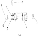
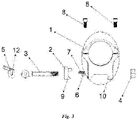
- the scope mounting system With the scope mounting system, the scope is positioned inside the housing (1). It is then fixed inside the body (1) by tightening the screws (8) present on the body (1). To attach the housing (1) to the picatinny rail, first the channel located on the bottom of the housing (1) is placed on the picatinny rail. The housing boss (10) located on one side of the channel engages the Picatinny rail.
- the flank (2) is attached to the recess made perpendicular to the channel.
- the springs (7) are positioned between the flank (2) and the housing (1).
- the threaded end of the locking screw (3) is passed through the recess, through the bore made in the flank (2), and then exits to the outside of the housing (1).
- An adjusting nut (4) is fitted to this threaded end of the locking screw (3) which protrudes outwards from the housing (1). Tightening the adjusting nut (4) enables the flank (2) to be fastened to the housing (1).
- the specially designed adjusting nut (4) controls how much force the flank (2) exerts on the rim the Picatinny rail exerts.
- This adjusting nut (4) is designed to have 12 steps in the form of teeth and a 30 degree interval between each step. When tightening the adjusting nut, pressure is applied to the springs (7).
- the locking lever (5) is attached to the head-shaped end of the locking screw (3) with a pin (6).
- the pin (6) runs through the hole in the locking lever (12) and through the hole in the locking screw (3) at the head-shaped end. This pin (6) can be used to rotate the locking lever (5) at the head-shaped end of the locking screw (3).
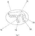
- the distance between the side surface (13) of the locking lever (5) and the hole (12) in the locking lever (5) is smaller than the distance between the surface (11) of the locking lever (5) and the hole (12) in the locking lever (5).
- the side surface (13) of the locking lever (5) comes to rest on the flank (2) while the locking lever (5) is not active.
- the locking lever (5) is moved in a rotating manner, the surface (11) of the locking lever (5) starts to abut the flank (2). Since the bore (12) of the locking lever (5) remains fixed with respect to the head-shaped end, the flank (2) is displaced in the direction of the housing projection (10) and locking is made possible.
- connection (locking) of the telescopic sight mounting system to the Picatinny rail can be carried out entirely by hand and no additional equipment (such as wrenches, screwdrivers and the like) is required.
- Unlocking or releasing the lock, including the lock on large caliber weapons, of the specially designed locking lever (5), which secures itself during its locked state, is not possible other than unlocking by external hand (finger) intervention.
- the unlocking of the specially designed locking lever (5) is achieved by turning it 68 degrees. Therefore, the product is advantageous over other generic systems that require 180 degree rotation.
- the specially designed locking lever (5) can be movably positioned up and down. In this way, enhanced aesthetics and more practical ease of use are provided.
- This scope mounting system ensures precise adjustment of the mounting product without the use of an additional tool. Thanks to its design, the locking lever (5) secures itself without the need for an additional component and enables fast and practical locking in a small space. Since the locking lever (5) is positioned horizontally (not parallel) with respect to the direction of the shot (with respect to the recoil force that occurs after the shot), it is self-locking.
- a ball (14) is at least partially inserted, as in 6 shown, can intervene.
- This ball (14) produces an audible click for each incremental rotation of the adjusting nut (4), the incremental setting being established when the ball (14) is positioned to be locked within a recess.
- the ball (14) is arranged in the housing between the outer circumference of the adjusting nut (4) and an adjusting screw (15).
- the ball (14) can be secured in the housing on the one hand and a force can be applied to the ball (14) by means of the adjusting screw (15) on the other hand, so that the ball (14) slides into the recesses of the adjusting nut (4).
- the adjusting screw (15) is preferably arranged in a recess in the housing in such a way that the axis of rotation of the adjusting screw (15) is arranged perpendicular to the axis of rotation of the adjusting nut (4).
- the ball (14) By tightening the adjusting screw (15), the ball (14) can be fixed in a recess and also the adjusting nut (4) are fixed in position, since further rotation is prevented by the engagement of the fixed ball (14) in a recess of the adjusting nut (4).
- an adjusting spring (16) is placed between the ball (14) and the adjusting screw (15), as shown in 6 and 7 shown, is arranged.
- This adjusting spring (16) can apply a spring force to the ball (14), the ball (14) sliding into the recesses of the adjusting nut (4) due to the spring force without fixing the ball (14) in a recess and thus preventing the rotation of the adjusting nut (4) because the adjusting nut (4) can be turned further against the resistance of the spring force of the adjusting spring (16).
- the operator receives both direct haptic feedback via the adjusting nut (4) during the adjustment of the telescopic sight mounting system, caused by overcoming the spring force necessary to set the next stage, and acoustic feedback due to the audible click with each rotation of the Adjusting nut (4) by one step.
- the step setting can be done in a simple manner, without additional tools, while minimizing errors due to the direct feedback via the adjusting nut (4) during the setting.
Landscapes
- Engineering & Computer Science (AREA)
- General Engineering & Computer Science (AREA)
- Clamps And Clips (AREA)
- Mutual Connection Of Rods And Tubes (AREA)
- Aiming, Guidance, Guns With A Light Source, Armor, Camouflage, And Targets (AREA)
Applications Claiming Priority (2)
| Application Number | Priority Date | Filing Date | Title |
|---|---|---|---|
| TR201912480 | 2019-08-20 | ||
| DE202019106611.3U DE202019106611U1 (de) | 2019-08-20 | 2019-11-27 | Zielfernrohr-Montagesystem mit Verriegelungshebel |
Publications (2)
| Publication Number | Publication Date |
|---|---|
| EP3783294A1 EP3783294A1 (de) | 2021-02-24 |
| EP3783294B1 true EP3783294B1 (de) | 2022-11-16 |
Family
ID=69148537
Family Applications (1)
| Application Number | Title | Priority Date | Filing Date |
|---|---|---|---|
| EP20186863.5A Active EP3783294B1 (de) | 2019-08-20 | 2020-07-21 | Zielfernrohr-montagesystem mit verriegelungshebel |
Country Status (3)
| Country | Link |
|---|---|
| EP (1) | EP3783294B1 (pl) |
| DE (1) | DE202019106611U1 (pl) |
| PL (1) | PL3783294T3 (pl) |
Cited By (1)
| Publication number | Priority date | Publication date | Assignee | Title |
|---|---|---|---|---|
| DE202023000163U1 (de) | 2023-01-25 | 2023-03-15 | Recknagel Gmbh & Co. Kg | Klemmsystem für Zusatzgeräte auf einer Picatinny-Schiene |
Families Citing this family (1)
| Publication number | Priority date | Publication date | Assignee | Title |
|---|---|---|---|---|
| DE202021103698U1 (de) * | 2021-07-09 | 2021-08-03 | Michael Ali Kilic | Montagesystem für Zieleinrichtung und Zusatzeinrichtung |
Family Cites Families (10)
| Publication number | Priority date | Publication date | Assignee | Title |
|---|---|---|---|---|
| DE4133242C1 (en) | 1991-10-08 | 1992-10-22 | Horst Blaser Jagdwaffenfabrik, 7972 Isny, De | Telescopic sight mounting on rifle - has fixed front foot and linear sliding rear foot |
| US5533267A (en) | 1995-03-01 | 1996-07-09 | Haight, Jr.; Sidney C. | Flexible one-piece scope ring |
| DE20203745U1 (de) * | 2002-03-08 | 2002-09-05 | Kilic, Ali, 97534 Waigolshausen | Vorrichtung zur Befestigung einer Zieleinrichtung an einer Waffe |
| US6931779B1 (en) | 2003-06-05 | 2005-08-23 | Daniel Galuppo, Jr. | Mounting device for attaching an auxiliary sight to a firearm |
| US7559167B1 (en) | 2003-12-02 | 2009-07-14 | Grip Pod Systems, Llc | Dual light rails and accessory rail mounts for vertical foregrips |
| US7685759B2 (en) * | 2006-11-01 | 2010-03-30 | Wilcox Industries Corp. | Three-point clamp for firearm mounting rail |
| US8312668B2 (en) * | 2008-11-20 | 2012-11-20 | Abrams Airborne Inc | Firearm mounting mechanism |
| CN101968333A (zh) * | 2010-08-31 | 2011-02-09 | 珠海市春秋光学仪器有限公司 | 一种偏心手柄装置 |
| US8806796B1 (en) * | 2013-02-22 | 2014-08-19 | Prezine, Llc | Cam lever mount |
| GB2515549A (en) * | 2013-06-27 | 2014-12-31 | Paul Oglesby | Mount for a firearm |
-
2019
- 2019-11-27 DE DE202019106611.3U patent/DE202019106611U1/de active Active
-
2020
- 2020-07-21 PL PL20186863.5T patent/PL3783294T3/pl unknown
- 2020-07-21 EP EP20186863.5A patent/EP3783294B1/de active Active
Cited By (3)
| Publication number | Priority date | Publication date | Assignee | Title |
|---|---|---|---|---|
| DE202023000163U1 (de) | 2023-01-25 | 2023-03-15 | Recknagel Gmbh & Co. Kg | Klemmsystem für Zusatzgeräte auf einer Picatinny-Schiene |
| EP4407271A1 (de) | 2023-01-25 | 2024-07-31 | RECKNAGEL GmbH & Co. KG | Klemmsystem für zusatzgeräte auf einer picatinny-schiene |
| US12571613B2 (en) | 2023-01-25 | 2026-03-10 | Recknagel Gmbh & Co. Kg | Clamping system for accessories on a Picatinny rail |
Also Published As
| Publication number | Publication date |
|---|---|
| EP3783294A1 (de) | 2021-02-24 |
| PL3783294T3 (pl) | 2023-06-12 |
| DE202019106611U1 (de) | 2019-12-18 |
Similar Documents
| Publication | Publication Date | Title |
|---|---|---|
| DE102011013575B4 (de) | Vorrichtung zum Befestigen eines Zusatzgerätes an einer Schusswaffe | |
| EP2122292B1 (de) | Anschlussstück und anschlussstück mit visierelement | |
| EP3649424B1 (de) | Vorrichtung zur einstellung der ausrichtung eines hinterschafts einer handfeuerwaffe | |
| CH654908A5 (de) | Schusswaffe fuer das praezisionsschiessen. | |
| DE102018132756B4 (de) | Umrüstsatz für eine Kurzwaffe | |
| DE2057995B2 (de) | Laufhalterung für Wechselläufe an Handfeuerwaffen | |
| DE2157420A1 (de) | Waffenlauf-befestigungs- und auswechselvorrichtung an handfeuerwaffen | |
| EP2956732B1 (de) | Universelle zielfernrohrmontage für handfeuerwaffen | |
| DE3637012A1 (de) | Faustfeuerwaffe mit zielfernrohr | |
| EP3783294A1 (de) | Zielfernrohr-montagesystem mit verriegelungshebel | |
| EP3553457A1 (de) | Vorrichtung zur variablen befestigung zweier optikeinrichtungen an einer waffe | |
| EP3973244B1 (de) | Obergehäuse für eine feuerwaffe | |
| EP4116664A1 (de) | Montagesystem für zieleinrichtung und zusatzeinrichtung | |
| EP4224110B1 (de) | Verstellbare visiereinrichtung | |
| DE102006024508B4 (de) | Halterung für Zusatzgeräte an Feuerwaffen | |
| DE3128848C2 (pl) | ||
| DE202018101992U1 (de) | Vorrichtung zur variablen Befestigung zweier Optikeinrichtungen an einer Waffe | |
| DE3204152C2 (de) | Vorrichtung zur Befestigung eines Zielfernrohres an einer Schußwaffe | |
| DE4007530C1 (en) | Telescopic sight for rifle - has front foot with bayonet coupling and rear foot with locking device | |
| DE19856248A1 (de) | Feuerwaffen und Zubehör | |
| DE102007010192A1 (de) | Einrichtung zum Abstützen einer Waffe | |
| WO2007087866A1 (de) | Adapter für ein gewehr | |
| DE406610C (de) | Befestigung des Laufes am Schlossgehaeuse von Schusswaffen | |
| EP4040098A1 (de) | Vorrichtung zur befestigung einer zusatzeinrichtung auf einer schusswaffe | |
| EP3303979B1 (de) | Halterung für zusatzgeräte an handwaffen |
Legal Events
| Date | Code | Title | Description |
|---|---|---|---|
| PUAI | Public reference made under article 153(3) epc to a published international application that has entered the european phase |
Free format text: ORIGINAL CODE: 0009012 |
|
| STAA | Information on the status of an ep patent application or granted ep patent |
Free format text: STATUS: THE APPLICATION HAS BEEN PUBLISHED |
|
| AK | Designated contracting states |
Kind code of ref document: A1 Designated state(s): AL AT BE BG CH CY CZ DE DK EE ES FI FR GB GR HR HU IE IS IT LI LT LU LV MC MK MT NL NO PL PT RO RS SE SI SK SM TR |
|
| AX | Request for extension of the european patent |
Extension state: BA ME |
|
| STAA | Information on the status of an ep patent application or granted ep patent |
Free format text: STATUS: REQUEST FOR EXAMINATION WAS MADE |
|
| 17P | Request for examination filed |
Effective date: 20210409 |
|
| RBV | Designated contracting states (corrected) |
Designated state(s): AL AT BE BG CH CY CZ DE DK EE ES FI FR GB GR HR HU IE IS IT LI LT LU LV MC MK MT NL NO PL PT RO RS SE SI SK SM TR |
|
| STAA | Information on the status of an ep patent application or granted ep patent |
Free format text: STATUS: EXAMINATION IS IN PROGRESS |
|
| 17Q | First examination report despatched |
Effective date: 20211007 |
|
| GRAP | Despatch of communication of intention to grant a patent |
Free format text: ORIGINAL CODE: EPIDOSNIGR1 |
|
| STAA | Information on the status of an ep patent application or granted ep patent |
Free format text: STATUS: GRANT OF PATENT IS INTENDED |
|
| INTG | Intention to grant announced |
Effective date: 20220621 |
|
| GRAS | Grant fee paid |
Free format text: ORIGINAL CODE: EPIDOSNIGR3 |
|
| GRAA | (expected) grant |
Free format text: ORIGINAL CODE: 0009210 |
|
| STAA | Information on the status of an ep patent application or granted ep patent |
Free format text: STATUS: THE PATENT HAS BEEN GRANTED |
|
| AK | Designated contracting states |
Kind code of ref document: B1 Designated state(s): AL AT BE BG CH CY CZ DE DK EE ES FI FR GB GR HR HU IE IS IT LI LT LU LV MC MK MT NL NO PL PT RO RS SE SI SK SM TR |
|
| REG | Reference to a national code |
Ref country code: GB Ref legal event code: FG4D Free format text: NOT ENGLISH |
|
| REG | Reference to a national code |
Ref country code: CH Ref legal event code: EP |
|
| REG | Reference to a national code |
Ref country code: IE Ref legal event code: FG4D Free format text: LANGUAGE OF EP DOCUMENT: GERMAN |
|
| REG | Reference to a national code |
Ref country code: DE Ref legal event code: R096 Ref document number: 502020001995 Country of ref document: DE |
|
| REG | Reference to a national code |
Ref country code: AT Ref legal event code: REF Ref document number: 1531996 Country of ref document: AT Kind code of ref document: T Effective date: 20221215 |
|
| REG | Reference to a national code |
Ref country code: LT Ref legal event code: MG9D |
|
| REG | Reference to a national code |
Ref country code: NL Ref legal event code: MP Effective date: 20221116 |
|
| PG25 | Lapsed in a contracting state [announced via postgrant information from national office to epo] |
Ref country code: SE Free format text: LAPSE BECAUSE OF FAILURE TO SUBMIT A TRANSLATION OF THE DESCRIPTION OR TO PAY THE FEE WITHIN THE PRESCRIBED TIME-LIMIT Effective date: 20221116 Ref country code: PT Free format text: LAPSE BECAUSE OF FAILURE TO SUBMIT A TRANSLATION OF THE DESCRIPTION OR TO PAY THE FEE WITHIN THE PRESCRIBED TIME-LIMIT Effective date: 20230316 Ref country code: NO Free format text: LAPSE BECAUSE OF FAILURE TO SUBMIT A TRANSLATION OF THE DESCRIPTION OR TO PAY THE FEE WITHIN THE PRESCRIBED TIME-LIMIT Effective date: 20230216 Ref country code: LT Free format text: LAPSE BECAUSE OF FAILURE TO SUBMIT A TRANSLATION OF THE DESCRIPTION OR TO PAY THE FEE WITHIN THE PRESCRIBED TIME-LIMIT Effective date: 20221116 Ref country code: FI Free format text: LAPSE BECAUSE OF FAILURE TO SUBMIT A TRANSLATION OF THE DESCRIPTION OR TO PAY THE FEE WITHIN THE PRESCRIBED TIME-LIMIT Effective date: 20221116 Ref country code: ES Free format text: LAPSE BECAUSE OF FAILURE TO SUBMIT A TRANSLATION OF THE DESCRIPTION OR TO PAY THE FEE WITHIN THE PRESCRIBED TIME-LIMIT Effective date: 20221116 |
|
| PG25 | Lapsed in a contracting state [announced via postgrant information from national office to epo] |
Ref country code: RS Free format text: LAPSE BECAUSE OF FAILURE TO SUBMIT A TRANSLATION OF THE DESCRIPTION OR TO PAY THE FEE WITHIN THE PRESCRIBED TIME-LIMIT Effective date: 20221116 Ref country code: LV Free format text: LAPSE BECAUSE OF FAILURE TO SUBMIT A TRANSLATION OF THE DESCRIPTION OR TO PAY THE FEE WITHIN THE PRESCRIBED TIME-LIMIT Effective date: 20221116 Ref country code: IS Free format text: LAPSE BECAUSE OF FAILURE TO SUBMIT A TRANSLATION OF THE DESCRIPTION OR TO PAY THE FEE WITHIN THE PRESCRIBED TIME-LIMIT Effective date: 20230316 Ref country code: HR Free format text: LAPSE BECAUSE OF FAILURE TO SUBMIT A TRANSLATION OF THE DESCRIPTION OR TO PAY THE FEE WITHIN THE PRESCRIBED TIME-LIMIT Effective date: 20221116 Ref country code: GR Free format text: LAPSE BECAUSE OF FAILURE TO SUBMIT A TRANSLATION OF THE DESCRIPTION OR TO PAY THE FEE WITHIN THE PRESCRIBED TIME-LIMIT Effective date: 20230217 |
|
| P01 | Opt-out of the competence of the unified patent court (upc) registered |
Effective date: 20230517 |
|
| PG25 | Lapsed in a contracting state [announced via postgrant information from national office to epo] |
Ref country code: NL Free format text: LAPSE BECAUSE OF FAILURE TO SUBMIT A TRANSLATION OF THE DESCRIPTION OR TO PAY THE FEE WITHIN THE PRESCRIBED TIME-LIMIT Effective date: 20221116 |
|
| PG25 | Lapsed in a contracting state [announced via postgrant information from national office to epo] |
Ref country code: SM Free format text: LAPSE BECAUSE OF FAILURE TO SUBMIT A TRANSLATION OF THE DESCRIPTION OR TO PAY THE FEE WITHIN THE PRESCRIBED TIME-LIMIT Effective date: 20221116 Ref country code: RO Free format text: LAPSE BECAUSE OF FAILURE TO SUBMIT A TRANSLATION OF THE DESCRIPTION OR TO PAY THE FEE WITHIN THE PRESCRIBED TIME-LIMIT Effective date: 20221116 Ref country code: EE Free format text: LAPSE BECAUSE OF FAILURE TO SUBMIT A TRANSLATION OF THE DESCRIPTION OR TO PAY THE FEE WITHIN THE PRESCRIBED TIME-LIMIT Effective date: 20221116 Ref country code: DK Free format text: LAPSE BECAUSE OF FAILURE TO SUBMIT A TRANSLATION OF THE DESCRIPTION OR TO PAY THE FEE WITHIN THE PRESCRIBED TIME-LIMIT Effective date: 20221116 Ref country code: CZ Free format text: LAPSE BECAUSE OF FAILURE TO SUBMIT A TRANSLATION OF THE DESCRIPTION OR TO PAY THE FEE WITHIN THE PRESCRIBED TIME-LIMIT Effective date: 20221116 |
|
| REG | Reference to a national code |
Ref country code: DE Ref legal event code: R097 Ref document number: 502020001995 Country of ref document: DE |
|
| PG25 | Lapsed in a contracting state [announced via postgrant information from national office to epo] |
Ref country code: SK Free format text: LAPSE BECAUSE OF FAILURE TO SUBMIT A TRANSLATION OF THE DESCRIPTION OR TO PAY THE FEE WITHIN THE PRESCRIBED TIME-LIMIT Effective date: 20221116 Ref country code: AL Free format text: LAPSE BECAUSE OF FAILURE TO SUBMIT A TRANSLATION OF THE DESCRIPTION OR TO PAY THE FEE WITHIN THE PRESCRIBED TIME-LIMIT Effective date: 20221116 |
|
| PGFP | Annual fee paid to national office [announced via postgrant information from national office to epo] |
Ref country code: PL Payment date: 20230630 Year of fee payment: 4 |
|
| PLBE | No opposition filed within time limit |
Free format text: ORIGINAL CODE: 0009261 |
|
| STAA | Information on the status of an ep patent application or granted ep patent |
Free format text: STATUS: NO OPPOSITION FILED WITHIN TIME LIMIT |
|
| 26N | No opposition filed |
Effective date: 20230817 |
|
| PGFP | Annual fee paid to national office [announced via postgrant information from national office to epo] |
Ref country code: CH Payment date: 20230801 Year of fee payment: 4 |
|
| PG25 | Lapsed in a contracting state [announced via postgrant information from national office to epo] |
Ref country code: SI Free format text: LAPSE BECAUSE OF FAILURE TO SUBMIT A TRANSLATION OF THE DESCRIPTION OR TO PAY THE FEE WITHIN THE PRESCRIBED TIME-LIMIT Effective date: 20221116 |
|
| PGFP | Annual fee paid to national office [announced via postgrant information from national office to epo] |
Ref country code: FR Payment date: 20230724 Year of fee payment: 4 |
|
| PG25 | Lapsed in a contracting state [announced via postgrant information from national office to epo] |
Ref country code: MC Free format text: LAPSE BECAUSE OF FAILURE TO SUBMIT A TRANSLATION OF THE DESCRIPTION OR TO PAY THE FEE WITHIN THE PRESCRIBED TIME-LIMIT Effective date: 20221116 |
|
| PG25 | Lapsed in a contracting state [announced via postgrant information from national office to epo] |
Ref country code: MC Free format text: LAPSE BECAUSE OF FAILURE TO SUBMIT A TRANSLATION OF THE DESCRIPTION OR TO PAY THE FEE WITHIN THE PRESCRIBED TIME-LIMIT Effective date: 20221116 |
|
| REG | Reference to a national code |
Ref country code: BE Ref legal event code: MM Effective date: 20230731 |
|
| PG25 | Lapsed in a contracting state [announced via postgrant information from national office to epo] |
Ref country code: LU Free format text: LAPSE BECAUSE OF NON-PAYMENT OF DUE FEES Effective date: 20230721 |
|
| PG25 | Lapsed in a contracting state [announced via postgrant information from national office to epo] |
Ref country code: LU Free format text: LAPSE BECAUSE OF NON-PAYMENT OF DUE FEES Effective date: 20230721 |
|
| REG | Reference to a national code |
Ref country code: IE Ref legal event code: MM4A |
|
| PG25 | Lapsed in a contracting state [announced via postgrant information from national office to epo] |
Ref country code: IT Free format text: LAPSE BECAUSE OF FAILURE TO SUBMIT A TRANSLATION OF THE DESCRIPTION OR TO PAY THE FEE WITHIN THE PRESCRIBED TIME-LIMIT Effective date: 20221116 Ref country code: BE Free format text: LAPSE BECAUSE OF NON-PAYMENT OF DUE FEES Effective date: 20230731 |
|
| PG25 | Lapsed in a contracting state [announced via postgrant information from national office to epo] |
Ref country code: IE Free format text: LAPSE BECAUSE OF NON-PAYMENT OF DUE FEES Effective date: 20230721 |
|
| PG25 | Lapsed in a contracting state [announced via postgrant information from national office to epo] |
Ref country code: IE Free format text: LAPSE BECAUSE OF NON-PAYMENT OF DUE FEES Effective date: 20230721 |
|
| PGFP | Annual fee paid to national office [announced via postgrant information from national office to epo] |
Ref country code: DE Payment date: 20240923 Year of fee payment: 5 |
|
| PG25 | Lapsed in a contracting state [announced via postgrant information from national office to epo] |
Ref country code: BG Free format text: LAPSE BECAUSE OF FAILURE TO SUBMIT A TRANSLATION OF THE DESCRIPTION OR TO PAY THE FEE WITHIN THE PRESCRIBED TIME-LIMIT Effective date: 20221116 |
|
| PG25 | Lapsed in a contracting state [announced via postgrant information from national office to epo] |
Ref country code: BG Free format text: LAPSE BECAUSE OF FAILURE TO SUBMIT A TRANSLATION OF THE DESCRIPTION OR TO PAY THE FEE WITHIN THE PRESCRIBED TIME-LIMIT Effective date: 20221116 |
|
| REG | Reference to a national code |
Ref country code: CH Ref legal event code: PL |
|
| GBPC | Gb: european patent ceased through non-payment of renewal fee |
Effective date: 20240721 |
|
| PG25 | Lapsed in a contracting state [announced via postgrant information from national office to epo] |
Ref country code: CH Free format text: LAPSE BECAUSE OF NON-PAYMENT OF DUE FEES Effective date: 20240731 |
|
| PG25 | Lapsed in a contracting state [announced via postgrant information from national office to epo] |
Ref country code: FR Free format text: LAPSE BECAUSE OF NON-PAYMENT OF DUE FEES Effective date: 20240731 |
|
| PG25 | Lapsed in a contracting state [announced via postgrant information from national office to epo] |
Ref country code: GB Free format text: LAPSE BECAUSE OF NON-PAYMENT OF DUE FEES Effective date: 20240721 |
|
| PG25 | Lapsed in a contracting state [announced via postgrant information from national office to epo] |
Ref country code: CY Free format text: LAPSE BECAUSE OF FAILURE TO SUBMIT A TRANSLATION OF THE DESCRIPTION OR TO PAY THE FEE WITHIN THE PRESCRIBED TIME-LIMIT; INVALID AB INITIO Effective date: 20200721 |
|
| PG25 | Lapsed in a contracting state [announced via postgrant information from national office to epo] |
Ref country code: HU Free format text: LAPSE BECAUSE OF FAILURE TO SUBMIT A TRANSLATION OF THE DESCRIPTION OR TO PAY THE FEE WITHIN THE PRESCRIBED TIME-LIMIT; INVALID AB INITIO Effective date: 20200721 |
|
| PGFP | Annual fee paid to national office [announced via postgrant information from national office to epo] |
Ref country code: AT Payment date: 20251020 Year of fee payment: 5 |
|
| PG25 | Lapsed in a contracting state [announced via postgrant information from national office to epo] |
Ref country code: TR Free format text: LAPSE BECAUSE OF FAILURE TO SUBMIT A TRANSLATION OF THE DESCRIPTION OR TO PAY THE FEE WITHIN THE PRESCRIBED TIME-LIMIT Effective date: 20221116 |
|
| PG25 | Lapsed in a contracting state [announced via postgrant information from national office to epo] |
Ref country code: PL Free format text: LAPSE BECAUSE OF NON-PAYMENT OF DUE FEES Effective date: 20240721 |
|
| REG | Reference to a national code |
Ref country code: DE Ref legal event code: R119 Ref document number: 502020001995 Country of ref document: DE |
|
| PG25 | Lapsed in a contracting state [announced via postgrant information from national office to epo] |
Ref country code: DE Free format text: LAPSE BECAUSE OF NON-PAYMENT OF DUE FEES Effective date: 20260203 |