EP3783248A1 - Prozessanschluss mit einer ringförmigen formdichtung - Google Patents
Prozessanschluss mit einer ringförmigen formdichtung Download PDFInfo
- Publication number
- EP3783248A1 EP3783248A1 EP20187890.7A EP20187890A EP3783248A1 EP 3783248 A1 EP3783248 A1 EP 3783248A1 EP 20187890 A EP20187890 A EP 20187890A EP 3783248 A1 EP3783248 A1 EP 3783248A1
- Authority
- EP
- European Patent Office
- Prior art keywords
- molded seal
- process connection
- seal
- measuring probe
- hold
- Prior art date
- Legal status (The legal status is an assumption and is not a legal conclusion. Google has not performed a legal analysis and makes no representation as to the accuracy of the status listed.)
- Granted
Links
Images




Classifications
-
- F—MECHANICAL ENGINEERING; LIGHTING; HEATING; WEAPONS; BLASTING
- F16—ENGINEERING ELEMENTS AND UNITS; GENERAL MEASURES FOR PRODUCING AND MAINTAINING EFFECTIVE FUNCTIONING OF MACHINES OR INSTALLATIONS; THERMAL INSULATION IN GENERAL
- F16J—PISTONS; CYLINDERS; SEALINGS
- F16J15/00—Sealings
- F16J15/02—Sealings between relatively-stationary surfaces
- F16J15/06—Sealings between relatively-stationary surfaces with solid packing compressed between sealing surfaces
- F16J15/062—Sealings between relatively-stationary surfaces with solid packing compressed between sealing surfaces characterised by the geometry of the seat
-
- F—MECHANICAL ENGINEERING; LIGHTING; HEATING; WEAPONS; BLASTING
- F16—ENGINEERING ELEMENTS AND UNITS; GENERAL MEASURES FOR PRODUCING AND MAINTAINING EFFECTIVE FUNCTIONING OF MACHINES OR INSTALLATIONS; THERMAL INSULATION IN GENERAL
- F16J—PISTONS; CYLINDERS; SEALINGS
- F16J15/00—Sealings
- F16J15/02—Sealings between relatively-stationary surfaces
- F16J15/06—Sealings between relatively-stationary surfaces with solid packing compressed between sealing surfaces
- F16J15/10—Sealings between relatively-stationary surfaces with solid packing compressed between sealing surfaces with non-metallic packing
- F16J15/104—Sealings between relatively-stationary surfaces with solid packing compressed between sealing surfaces with non-metallic packing characterised by structure
-
- F—MECHANICAL ENGINEERING; LIGHTING; HEATING; WEAPONS; BLASTING
- F16—ENGINEERING ELEMENTS AND UNITS; GENERAL MEASURES FOR PRODUCING AND MAINTAINING EFFECTIVE FUNCTIONING OF MACHINES OR INSTALLATIONS; THERMAL INSULATION IN GENERAL
- F16J—PISTONS; CYLINDERS; SEALINGS
- F16J15/00—Sealings
- F16J15/02—Sealings between relatively-stationary surfaces
- F16J15/06—Sealings between relatively-stationary surfaces with solid packing compressed between sealing surfaces
- F16J15/061—Sealings between relatively-stationary surfaces with solid packing compressed between sealing surfaces with positioning means
-
- F—MECHANICAL ENGINEERING; LIGHTING; HEATING; WEAPONS; BLASTING
- F16—ENGINEERING ELEMENTS AND UNITS; GENERAL MEASURES FOR PRODUCING AND MAINTAINING EFFECTIVE FUNCTIONING OF MACHINES OR INSTALLATIONS; THERMAL INSULATION IN GENERAL
- F16J—PISTONS; CYLINDERS; SEALINGS
- F16J15/00—Sealings
- F16J15/02—Sealings between relatively-stationary surfaces
- F16J15/06—Sealings between relatively-stationary surfaces with solid packing compressed between sealing surfaces
-
- F—MECHANICAL ENGINEERING; LIGHTING; HEATING; WEAPONS; BLASTING
- F16—ENGINEERING ELEMENTS AND UNITS; GENERAL MEASURES FOR PRODUCING AND MAINTAINING EFFECTIVE FUNCTIONING OF MACHINES OR INSTALLATIONS; THERMAL INSULATION IN GENERAL
- F16J—PISTONS; CYLINDERS; SEALINGS
- F16J15/00—Sealings
- F16J15/02—Sealings between relatively-stationary surfaces
- F16J15/06—Sealings between relatively-stationary surfaces with solid packing compressed between sealing surfaces
- F16J15/08—Sealings between relatively-stationary surfaces with solid packing compressed between sealing surfaces with exclusively metal packing
- F16J15/0818—Flat gaskets
-
- F—MECHANICAL ENGINEERING; LIGHTING; HEATING; WEAPONS; BLASTING
- F16—ENGINEERING ELEMENTS AND UNITS; GENERAL MEASURES FOR PRODUCING AND MAINTAINING EFFECTIVE FUNCTIONING OF MACHINES OR INSTALLATIONS; THERMAL INSULATION IN GENERAL
- F16J—PISTONS; CYLINDERS; SEALINGS
- F16J15/00—Sealings
- F16J15/16—Sealings between relatively-moving surfaces
- F16J15/32—Sealings between relatively-moving surfaces with elastic sealings, e.g. O-rings
- F16J15/3268—Mounting of sealing rings
-
- G—PHYSICS
- G01—MEASURING; TESTING
- G01F—MEASURING VOLUME, VOLUME FLOW, MASS FLOW OR LIQUID LEVEL; METERING BY VOLUME
- G01F15/00—Details of, or accessories for, apparatus of groups G01F1/00 - G01F13/00 insofar as such details or appliances are not adapted to particular types of such apparatus
- G01F15/18—Supports or connecting means for meters
-
- G—PHYSICS
- G01—MEASURING; TESTING
- G01L—MEASURING FORCE, STRESS, TORQUE, WORK, MECHANICAL POWER, MECHANICAL EFFICIENCY, OR FLUID PRESSURE
- G01L19/00—Details of, or accessories for, apparatus for measuring steady or quasi-steady pressure of a fluent medium insofar as such details or accessories are not special to particular types of pressure gauges
- G01L19/0007—Fluidic connecting means
Definitions
- the present invention relates to a process connection with an annular molded seal according to the preamble of claim 1.
- a process connection is used to mount a sensor in a process system in such a way that a measuring probe can protrude into the process environment and components of the sensor, such as a sensor housing with control buttons and display panels, are arranged outside the process environment, protected from the process environment.
- Such sensors are, for example, flow sensors or flow monitors from the applicant with the designation T-Easic FTS.
- Various sensors are known for determining process variables of a medium in a container, which for example measure the level or the temperature. Although there are also non-contact measuring methods, many sensors use a probe that is immersed in the medium to be measured. For example, it measures DE 10 2007 030 847 A1 known level measurement with time domain reflectometry (TDR) the transit time of microwave pulses guided in the probe to the surface of the medium.
- TDR time domain reflectometry
- the compression fittings are a common means of installing and connecting measuring probes or pipes in a process in process measurement technology.
- EHEDG European Hygienic Engineering & Design Group
- the compression fittings are not hygienically sealed. On the process side, there are many narrow gaps in which bacteria can settle.
- the EHEDG issues certifications for products in the field of hygienic process measurement technology.
- the EHEDG has various guidelines for construction in the hygienic area of food contact.
- the DOC25 guideline describes how mechanical seals should look for hygienic applications. They should be constructed in the form of a lip seal. However, such lip seals are not sufficiently pressure-resistant.
- a common method of creating hygienic connections between components is to weld the components together.
- the weld seam ensures that there is a gap-free transition between the sensor housing and the process connection.
- this connection cannot be released again by the user.
- the process connection is firmly fixed and can no longer be changed.
- One object of the invention is to provide a process connection which, according to the EHEDG, is considered hygienic and tight and at the same time can be variably positioned on a measuring probe of a process measuring sensor system.
- a further object of the invention is to provide a process connection or an adapter with which it is possible to provide a hygienic process connection for a sensor by means of a commercially available compression fitting and the process connection.
- the process connection should be flexibly positionable on the measuring probe and exchangeable.
- the object is achieved according to claim 1 by a process connection with an annular shaped seal and a cylindrical measuring probe of a sensor, the shaped seal being provided for sealing off a process environment, the shaped seal being between the process connection and the measuring probe, the shaped seal being fixable by means of a hold-down device, the molded seal rests on a first annular sealing edge on the process connection, the molded seal encloses the cylindrical measuring probe on a second annular sealing edge, the molded seal has at least one outer circumferential conical surface with an outer circumferential cone angle and the process connection has an inner conical surface with an inner conical angle, the shaped seal on the first annular Sealing edge of the inner conical surface of the The process connection, the outer circumferential taper angle being smaller than the inner taper angle.
- the process environment is tightly sealed off from an external environment.
- the process environment contains, for example, water or oil-based liquids.
- the process temperature is, for example, from -40 ° C to + 150 ° C.
- the process pressure is, for example, up to 16 bar.
- the molded seal is made of a flexible material, for example an elastomer (FKM, EPDM, NBR) or for example a silicone.
- the molded seal has a conical shape at the end which has the second annular sealing edge.
- the molded seal is inserted into a seal seat of the process connection. The hold-down applies a defined force to the molded seal.
- the molded seal is fixed using the hold-down device mounted in the process connection. During assembly, pressure forces are generated on the molded seal via the hold-down device. These compressive forces ensure that the molded seal with the conical shape is formed on the measuring probe and that the measuring probe is sealed without gaps. This makes the seal hygienic in the sense of the EHEDG.
- the hold-down presses the molded seal and seals the first annular sealing edge on the process connection hygienically without a gap.
- the outer circumferential cone angle of the outer circumferential conical surface of the molded seal is smaller than the inner conical angle of the inner conical surface of the process connection, as a result of which the molded seal lies tightly against the inner conical surface of the process connection on the first annular sealing edge.
- the first annular sealing edge is also, for example, on a flat side of the process connection which faces the process environment.
- the molded seal with the outer circumferential conical surface rests against the first annular sealing edge of the inner conical surface of the process connection.
- the second annular seal By pushing the measuring probe into the molded seal on the second annular seal, the second annular seal is displaced to the outside.
- the first annular sealing edge acts as a counter bearing or as a pivot point, which further increases the sealing effect on the first annular sealing edge.
- the molded seal Due to the shape of the molded seal, the molded seal has a self-reinforcing sealing edge function on the second annular sealing edge when the process pressure rises.
- a smallest diameter of the molded seal has, for example, a diameter of 7.6 mm and the measuring probe, for example, a diameter of 8 mm.
- the circumferential prestress for the second annular sealing edge is accordingly 0.2 mm circumferentially, for example.
- smaller or larger diameters of the molded seal or the measuring probe can also be provided.
- the hold-down device has a thread.
- the hold-down device can be pressed against the molded seal by a rotary movement. This means that high forces can be exerted on the molded seal. If the hold-down is implemented with the thread, the force can be applied by a defined torque.
- an insert ring is arranged between the hold-down device and the molded seal.
- the insert ring has, for example, a higher level of friction compared to the molded seal than compared to the hold-down device.
- a slide bearing is thus formed between the hold-down device and the insert ring when the hold-down device is installed. This means that only compressive forces are exerted on the molded seal and no torsional forces that could lead to the molded seal slipping. This ensures the position of the molded seal during assembly.
- the insert ring made of a hard material, for example steel, can be used. This insert ring ensures that the molded seal made of a soft material only bulges outwards. The insert ring remains in shape even after the force is applied by the hold-down device.
- the hold-down device has a projection that protrudes into the molded seal.
- the attachment can also be referred to as an attachment, since the attachment protrudes at least partially into the molded seal and thus stabilizes and / or positions the molded seal.
- the attachment on the hold-down device in a straight shape or in a conical shape can produce a desired effect of the undesired bulging of the molded seal inward toward the measuring probe.
- point-like knobs are arranged along a circumference on a circular cylindrical outer surface of the molded seal.
- a radial centering of the molded seal takes place in a cylindrical section or shoulder of the process connection, which is designed as a counter bearing of the molded seal.
- the knobs integrated in the molded seal ensure, on the one hand, a tolerance compensation between the bearing and the molded seal and, on the other hand, a sufficient air gap that serves as a displacement space for the molded seal. This displacement space is necessary because elastomers as a material for the molded seal are not compressible or compressible.
- the knobs can be easily integrated on the outer diameter of the molded seal by selecting a parting plane of the production tool accordingly.
- the molded seal remains seated in the seal seat of the process connection thanks to the knobs on the outside diameter and, for example, remains in shape.
- knobs are evenly distributed with equidistant spacings on the circular cylindrical outer surface.
- linear ribs are arranged along a circumference on a circular cylindrical inner surface of the molded seal, the linear ribs being parallel to one another.
- the measuring probe is centered with the linear ribs, also in a cylindrical part of the molded seal.
- the ribs integrated in the molded seal ensure, on the one hand, a tolerance compensation between the measuring probe and the molded seal, and on the other hand, a sufficient air gap that serves as a displacement space for the molded seal.
- the molded seal remains in place on the measuring probe through the ribs on the inside diameter and, for example, remains in shape.
- the ribs stabilize the molded seal so that it can withstand the forces of the hold-down device.
- four ribs are evenly distributed with equidistant intervals on the circular cylindrical inner surface.
- a contact surface of the molded seal for the hold-down device is perpendicular to a longitudinal axis of the measuring probe.
- the shaped seal on the second annular sealing edge has an acute angle in cross section.
- the molded seal has an inner conical lateral surface which faces the measuring probe.
- a cone angle of the inner conical lateral surface of the molded seal and an outer surface of the molded seal form an acute angle to one another.
- the molded seal is made of a flexible material, for example an elastomer (FKM, EPDM, NBR) or for example a silicone.
- the flexible material can have a hardness of 40-90 Shore A, in particular a hardness of 60 to 75 Shore A.
- the material with the hardness must be selected in such a way that the molded seal retains the correct shape in order to fulfill its sealing effect.
- the material itself depends on the type of application and the ambient conditions.
- the measuring probe is arranged displaceably in the molded seal. This means that the measuring probe can be adapted to the application or to the application.
- the molded seal can be retrofitted.
- the measuring probe can be installed afterwards or removed again at a later point in time.
- the process connection is preferably delivered preassembled so that the process connection is ready for connection for a customer.
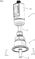
- Figure 1 shows a sensor 4 with a measuring probe 3 and a process connection 1.
- the process connection 1 separates a process environment 5 with process environment conditions from the environment in which the housing 19 of the sensor 4 is arranged.
- Sensor 4 here denotes the entire measuring device.
- the sensor 4 has at least one sensor element.
- FIG Figure 2 shows a section through the process connection 1 according to FIG Figure 1 .
- the molded seal 2 is shown in the assembled state and rests on the cylindrical measuring probe 3.
- the molded seal is fixed by mounting the hold-down device 6.
- the hold-down device is fixed by means of the compression fitting 21.
- the compression fitting 21 is sealed by means of a seal 22.
- the hold-down device optionally has a thread.
- the hold-down device can be pressed against the molded seal by a rotary movement.
- Figure 3 shows the molded seal 2 and a section through the molded seal 2 of the process connection 1 according to FIG Figure 2 in an enlarged view.
- Figure 3 shows the process connection 1 with an annular molded seal 2 and a cylindrical measuring probe 3 of a sensor 4, the molded seal 2 being provided for sealing a process environment 5, the molded seal 2 being between the process connection 1 and the measuring probe 3, the molded seal 2 by means of a hold-down device 6 (cf.
- Figure 2 is fixable, the molded seal 2 rests against a first annular sealing edge 7 on the process connection 1, the molded seal 2 encloses the cylindrical measuring probe 3 at a second annular sealing edge 8, the molded seal 2 has at least one outer circumferential conical surface 9 with an outer circumferential cone angle 10 and the process connection 1 has an inner conical surface 11 with an inner cone angle 12, the molded seal 2 resting against the first annular sealing edge 7 of the inner conical surface 11 of the process connection 1, the outer circumferential cone angle 10 being smaller than the inner cone angle 12.
- the outer circumferential cone angle 10 and the inner cone angle 12 are defined and indicated with respect to a longitudinal axis 17 of the measuring probe.
- the process environment 5 is tightly sealed off from an external environment.
- the process environment 5 there is, for example, water or oil-based ones Liquids.
- the process temperature is, for example, from -40 ° C to + 150 ° C.
- the process pressure is, for example, up to 16 bar.
- the molded seal 2 is made of a flexible material, in particular a flexible plastic.
- the molded seal 2 has a conical shape at the end which has or forms the second annular sealing edge 8.
- the molded seal 2 is inserted into a seal seat of the process connection 1.
- the hold-down 6 is mounted with a predefined force. If the hold-down device is implemented with a thread, for example, this force can be applied by a defined torque.
- the molded seal 2 is secured by means of the hold-down device mounted in the process connection 1 (cf. Figure 2 ) fixed. Through the assembly, compressive forces are generated on the molded seal 2 via the hold-down device. These compressive forces ensure that the molded seal 2 with the conical shape is molded onto the measuring probe 3 and the measuring probe 3 is sealed without a gap. As a result, the molded seal 2 or the sealing point is suitable for hygiene in the sense of the EHEDG.
- the hold-down presses the molded seal 2 and seals the first annular sealing edge 7 on the process connection 1 hygienically without a gap.
- the outer circumferential cone angle 10 of the outer circumferential conical surface 9 of the molded seal 2 is smaller than the internal conical angle 12 of the internal conical surface 11 of the process connection 1, as a result of which the molded seal 2 lies tightly against the first annular sealing edge 7 on the internal conical surface 11 of the process connection 1.
- the first annular sealing edge 7 is also, for example, on a plan side 20 of the process connection 1, which faces the process environment 5.
- the molded seal 2 with the outer jacket conical surface 9 therefore rests against the first annular sealing edge 7 of the inner conical surface 11 of the process connection 1.
- the second annular seal 8 By pushing the measuring probe 3 into the molded seal 2 on the second annular seal 8, the second annular seal 8 is displaced to the outside.
- the first annular sealing edge 7 acts as a counter bearing or as a pivot point, which further increases the sealing effect on the first annular sealing edge 7.
- the molded seal 2 Due to the shape of the molded seal 2, the molded seal 2 has a self-reinforcing sealing edge function on the second annular sealing edge 8 when the process pressure rises.
- a smallest diameter of the molded seal 2 has, for example, a diameter of 7.6 mm and the measuring probe 3, for example, a diameter of 8 mm.
- the circumferential prestress for the second annular sealing edge is accordingly 0.2 mm circumferentially, for example.
- punctiform knobs 13 are arranged along a circumference on a circular cylindrical outer surface.
- a radial centering of the molded seal 2 takes place according to Figure 3 in a cylindrical section or extension of the process connection 1, which is designed as a counter bearing of the molded seal 2.
- the knobs 13 integrated in the molded seal 2 ensure, on the one hand, a tolerance compensation between the bearing and the molded seal 2 and, on the other hand, a sufficient air gap, which serves as a displacement space for the molded seal 2. This displacement space is necessary because elastomers as a material for the molded seal are not compressible or compressible.
- the knobs 13 can be easily integrated on the outer diameter of the molded seal 2 by appropriately selecting a parting plane of the production tool.
- the molded seal 2 remains seated in the seal seat of the process connection 1 through the knobs 13 on the outside diameter and, for example, remains in shape.
- knobs 13 arranged evenly distributed with equidistant intervals on the circular cylindrical outer surface.
- Line-shaped ribs 15 are arranged along a circumference on a circular-cylindrical inner surface 14, the line-shaped ribs 15 being parallel to one another.
- the centering of the measuring probe 3 takes place according to Figure 3 with the linear ribs 15 also in a cylindrical part of the molded seal 2.
- the one in the molded seal 2 Integrated ribs 15 ensure, on the one hand, a tolerance compensation between the measuring probe 3 and the molded seal 2, and on the other hand, a sufficient air gap, which serves as a displacement space for the molded seal 2.
- ribs 15 in the inner diameter of the molded seal 2 allows the molded seal 2 to be easily removed from the mold during manufacture, so that there are no undercuts.
- the molded seal 2 remains seated on the measuring probe 3 by the ribs 15 on the inside diameter and, for example, remains in shape.
- the ribs 15 stabilize the molded seal 2 so that it withstands the forces of the hold-down device.
- Figure 7 shows a top view of the molded seal. According to Figure 7 For example, four ribs 15 are arranged evenly distributed at equidistant intervals on the circular cylindrical inner surface.
- Figure 6 shows a side view of the molded seal with the point-like knobs 13.
- Figure 3 is a contact surface 16 of the molded seal 2 for the hold-down device (cf. Figure 2 ) perpendicular to a longitudinal axis 17 of the measuring probe.
- the molded seal 2 is subjected to a compressive force parallel to the measuring probe 3.
- the molded seal 2 has an acute angle at the second annular sealing edge 8 in cross section.
- the sealing effect of the second annular sealing edge 8 is further increased, since the pressing forces on the second annular sealing edge 8 are increased.
- the molded seal 2 has an inner conical lateral surface 18 which faces the measuring probe 3.
- the molded seal is made of FKM, for example, and has a hardness of 70 Shore A.
- the measuring probe 3 is arranged displaceably in the molded seal 2. This means that the measuring probe can be adapted to the application or to the application.
- the molded seal 2 can be retrofitted.
- the measuring probe 3 can subsequently be mounted or removed again at a later point in time.
- the process connection 1 is preferably delivered preassembled so that the process connection 1 is ready for connection to a user.
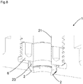
- an insert ring 23 is arranged between the hold-down device 6 and the molded seal 2.
- the insert ring 23, for example, has a higher friction compared to the molded seal 2 than compared to the hold-down device 6.
- a sliding bearing is formed between the hold-down device 6 and the insert ring 23 during the assembly of the hold-down device 6 Torsional forces that could lead to the molded seal 2 slipping.
- the insert ring 23 made of a hard material, for example steel or stainless steel, can be used. This insert ring 23 ensures that the molded seal 2 made of a soft material only bulges outward. The insert ring 23 remains in shape even after the force has been applied by the hold-down device 6.
- the hold-down device 6 has a projection 24 which protrudes into the molded seal 2.
- the attachment 24 can also be referred to as an attachment, since the attachment 24 protrudes at least partially into the molded seal 2 and thus stabilizes and / or positions the molded seal 2.
- the extension 24 has a straight or cylindrical shape.
- the extension 24 has a conical shape.
Landscapes
- Engineering & Computer Science (AREA)
- General Engineering & Computer Science (AREA)
- Mechanical Engineering (AREA)
- Physics & Mathematics (AREA)
- General Physics & Mathematics (AREA)
- Geometry (AREA)
- Fluid Mechanics (AREA)
- Gasket Seals (AREA)
- Measuring Fluid Pressure (AREA)
Abstract
Description
- Die vorliegende Erfindung betrifft einen Prozessanschluss mit einer ringförmigen Formdichtung nach dem Oberbegriff von Anspruch 1.
- Ein Prozessanschluss dient dazu, einen Sensor in einer Prozessanlage derart zu montieren, dass eine Messsonde in die Prozessumgebung ragen kann und Bestandteile des Sensors, wie ein Sensorgehäuse mit Bedientasten und Anzeigefeldern, außerhalb der Prozessumgebung geschützt vor der Prozessumgebung angeordnet sind.
- Derartige Sensoren sind beispielsweise Durchflusssensoren bzw. Durchflusswächter der Anmelderin mit der Bezeichnung T-Easic FTS.
- Zur Bestimmung von Prozessgrößen eines Mediums in einem Behälter sind diverse Sensoren bekannt, die beispielsweise den Füllstand oder die Temperatur messen. Obwohl es auch berührungslose Messverfahren gibt, nutzen viele Sensoren eine Sonde, die in das zu vermessende Medium eintaucht. So misst die beispielsweise aus
DE 10 2007 030 847 A1 bekannte Füllstandmessung mit Zeitbereichsreflektometrie (TDR, Time Domain Reflectometry) die Laufzeit von in der Sonde geführten Mikrowellenpulsen bis zur Oberfläche des Mediums. - Bei diesen Prozessanschlüssen handelt es sich um handelsübliche Klemmringverschraubungen, die als Katalogware erhältlich sind. Die Klemmringverschraubungen sind ein gängiges Mittel, um in der Prozessmesstechnik Messsonden oder auch Rohre in einem Prozess zu installieren und zu verbinden. Die Klemmringverschraubungen sind gemäß der European Hygienic Engineering & Design Group (EHEDG) nicht hygienisch dichtend. Es sind prozessseitig viele enge Spalten vorhanden, in denen sich Bakterien absetzen können.
- Die EHEDG vergibt Zertifizierungen für Produkte im Bereich von hygienischer Prozessmesstechnik.
- Die EHEDG hat verschiedene Guidelines für die Konstruktion im hygienischen Bereich Food-Contact. In der Guideline DOC25 ist beschrieben, wie Gleitringdichtungen für hygienische Anwendungen auszusehen haben. Sie sollen in Form einer Lippendichtung konstruiert werden. Jedoch sind derartige Lippendichtungen nicht genügend druckstabil.
- Weiter gibt es fest installierte Prozessanschlüsse an einem Sensorgehäuse. Eine gängige Methode, um hygienische Verbindungen von Bauteilen, beispielsweise einem Prozessanschluss an einem Sensorgehäuse zu schaffen, ist die Bauteile miteinander zu verschweißen. Die Schweißnaht sorgt dafür, dass es einen spaltfreien Übergang zwischen dem Sensorgehäuse und dem Prozessanschluss gibt. Allerdings kann diese Verbindung von dem Anwender nicht wieder gelöst werden. Der Prozessanschluss ist fest fixiert und kann nicht mehr verändert werden.
- Eine Aufgabe der Erfindung besteht darin, einen Prozessanschluss bereitzustellen, der gemäß der EHEDG als hygienetauglich gilt und dicht ist und gleichzeitig an einer Messsonde einer Prozessmesssensorik variabel positionierbar ist.
- Eine weitere Aufgabe der Erfindung besteht darin, einen Prozessanschluss bzw. einen Adapter bereitzustellen, mit dem es möglich ist, mittels einer handelsüblichen Klemmringverschraubung und dem Prozessanschluss einen hygienetauglichen Prozessanschluss für einen Sensor bereitzustellen. Der Prozessanschluss soll auf der Messsonde flexibel positionierbar sein und austauschbar sein.
- Die Aufgabe wird gemäß Anspruch 1 gelöst durch einen Prozessanschluss mit einer ringförmigen Formdichtung und einer zylindrischen Messsonde eines Sensors, wobei die Formdichtung zum Abdichten einer Prozessumgebung vorgesehen ist, wobei die Formdichtung zwischen dem Prozessanschluss und der Messsonde liegt, die Formdichtung mittels eines Niederhalter fixierbar ist, die Formdichtung an einer ersten ringförmigen Dichtkante an dem Prozessanschluss anliegt, die Formdichtung die zylindrische Messsonde an einer zweiten ringförmigen Dichtkante umschließt, die Formdichtung mindestens eine Außenmantelkegelfläche mit einem Außenmantelkegelwinkel aufweist und der Prozessanschluss eine Innenkegelfläche mit einem Innenkegelwinkel aufweist, wobei die Formdichtung an der ersten ringförmigen Dichtkante der Innenkegelfläche des Prozessanschlusses anliegt, wobei der Außenmantelkegelwinkel kleiner ist, als der Innenkegelwinkel.
- Dadurch ist die Prozessumgebung dicht gegenüber einer Außenumgebung abgedichtet. In der Prozessumgebung befinden sich beispielsweise Wasser oder ölbasierte Flüssigkeiten. Die Prozesstemperatur weist beispielsweise Temperaturen von -40°C bis +150°C auf. Der Prozessdruck beträgt beispielsweise bis zu 16 bar.
- Die Formdichtung ist aus einem flexiblem Werkstoff, zum Beispiel ein Elastomer (FKM, EPDM, NBR) oder beispielsweise aus einem Silikon gefertigt. Die Formdichtung weist an dem Ende, welches die zweite ringförmige Dichtkante aufweist, eine Konusform auf. Die Formdichtung wird in einen Dichtungssitz des Prozessanschlusses eingelegt. Der Niederhalter wirkt eine definierte Kraft auf die Formdichtung aus.
- Die Formdichtung wird mittels des in dem Prozessanschluss montierten Niederhalter fixiert. Über den Niederhalter werden durch die Montage Druckkräfte auf die Formdichtung erzeugt. Diese Druckkräfte sorgen dafür, dass sich die Formdichtung mit der Konusform an die Messsonde anformt und die Messsonde spaltfrei abdichtet. Dadurch ist die Dichtung im Sinn der EHEDG hygienetauglich. Der Niederhalter verpresst die Formdichtung und dichtet an der ersten ringförmigen Dichtkante an dem Prozessanschluss hygienisch ohne Spalt ab.
- Der Außenmantelkegelwinkel der Außenmantelkegelfläche der Formdichtung ist kleiner als der Innenkegelwinkel der Innenkegelfläche des Prozessanschlusses, wodurch die Formdichtung an der ersten ringförmigen Dichtkante an der Innenkegelfläche des Prozessanschlusses dicht anliegt. Die erste ringförmige Dichtkante liegt auch beispielsweise an einer Planseite des Prozessanschlusses, welche der Prozessumgebung zugewandt ist. Damit liegt die Formdichtung mit der Außenmantelkegelfläche an der ersten ringförmigen Dichtkante der Innenkegelfläche des Prozessanschlusses an.
- Durch das Einschieben der Messsonde in die Formdichtung an der zweiten ringförmigen Dichtung wird die zweite ringförmige Dichtung nach Außen verdrängt. Hierbei wirkt die erste ringförmige Dichtkante als Gegenlager bzw. als Drehpunkt, was die Dichtwirkung an der ersten ringförmigen Dichtkante weiter verstärkt.
- Durch die Form der Formdichtung hat die Formdichtung bei steigendem Prozessdruck eine selbstverstärkende Dichtkantenfunktion an der zweiten ringförmigen Dichtkante.
- Ein kleinster Durchmesser der Formdichtung hat beispielsweise einen Durchmesser von 7,6 mm und die Messsonde beispielsweise einen Durchmesser von 8 mm. Die umlaufende Vorspannung für die zweite ringförmige Dichtkante beträgt demnach umlaufend beispielsweise 0,2 mm.
- Es können gemäß der Erfindung auch kleinere oder größere Durchmesser der Formdichtung oder der Messsonde vorgesehen sein.
- In Weiterbildung der Erfindung weist der Niederhalter ein Gewinde auf. Dadurch kann der Niederhalter durch eine Drehbewegung gegen die Formdichtung gedrückt werden. Dadurch können hohe Kräfte auf die Formdichtung ausgeübt werden. Ist der Niederhalter mit dem Gewinde realisiert, kann die Kraft durch ein definiertes Drehmoment aufgebracht werden.
- In Weiterbildung der Erfindung ist zwischen dem Niederhalter und der Formdichtung ein Einlegering angeordnet. Der Einlegering ist weist beispielsweise gegenüber der Formdichtung eine höhere Reibung auf, als gegenüber dem Niederhalter. Damit bildet sich zwischen dem Niederhalter und dem Einlegering ein Gleitlager bei der Montage des Niederhalters. Damit werden auf die Formdichtung nur Druckkräfte ausgeübt und keine Drehkräfte, die zu einem Verrutschen der Formdichtung führen könnten. Somit wird die Position der Formdichtung bei der Montage gewährleistet.
- Um ein Auswölben der Formdichtung nach Innen zur Messsonde beim Beaufschlagen der Druckkraft durch den Niederhalter zu vermeiden, kann der Einlegering aus einem harten Werkstoff, zum Beispiel Stahl, eingesetzt werden. Dieser Einlegering sorgt dafür, dass sich die Formdichtung aus einem weichen Werkstoff nur nach außen wölbt. Der Einlegering bleibt auch nach Beaufschlagen der Kraft durch den Niederhalter weiterhin in Form.
- In Weiterbildung der Erfindung weist der Niederhalter einen Ansatz auf, der in die Formdichtung ragt. Der Ansatz kann auch als Vorsatz bezeichnet werden, da der Ansatz zumindest teilweise in die Formdichtung ragt und damit die Formdichtung stabilisiert und/oder positioniert.
- Beispielsweise kann der Ansatz am Niederhalter in gerader Form oder in kegeliger Form eine gewünschte Wirkung der nicht gewollten Auswölbung der Formdichtung nach Innen zur Messsonde erbringen.
- In Weiterbildung der Erfindung sind an einer kreiszylindrischen Außenfläche der Formdichtung punktförmige Noppen entlang eines Umfanges angeordnet.
- Eine radiale Zentrierung der Formdichtung erfolgt in einem zylindrischen Abschnitt oder Ansatz des Prozessanschlusses, welcher als Gegenlager der Formdichtung ausgebildet ist. Die in der Formdichtung integrierten Noppen sorgen zum einen für einen Toleranzausgleich zwischen Lagerung und Formdichtung, zum anderen für einen ausreichenden Luftspalt, der als Verdrängungsraum für die Formdichtung dient. Dieser Verdrängungsraum ist erforderlich, da Elastomere als Werkstoff für die Formdichtung nicht kompressibel bzw. komprimierbar sind.
- Am Außendurchmesser der Formdichtung lassen sich die Noppen einfach integrieren, indem eine Trennebene des Herstellungswerkzeuges entsprechend gewählt wird.
- Die Formdichtung bleibt durch die Noppen am Außendurchmesser im Dichtungssitz des Prozessanschlusses sitzen und beispielsweise in Form.
- Beispielsweise sind 8 Noppen gleichmäßig verteilt mit äquidistanten Abständen an der kreiszylindrischen Außenfläche angeordnet.
- In Weiterbildung der Erfindung sind an einer kreiszylindrischen Innenfläche der Formdichtung linienförmige Rippen entlang eines Umfangs angeordnet, wobei die linienförmigen Rippen parallel zueinander sind.
- Die Zentrierung der Messsonde erfolgt mit den linienförmigen Rippen ebenfalls in einem zylindrischen Teil der Formdichtung. Die in der Formdichtung integrierten Rippen sorgen zum einen für einen Toleranzausgleich zwischen Messsonde und Formdichtung, zum anderen für einen ausreichenden Luftspalt, der als Verdrängungsraum für die Formdichtung dient.
- Die Ausführung von Rippen im Innendurchmesser der Formdichtung erlaubt es, die Formdichtung bei der Herstellung einfach entformen zu können, so dass keine Hinterschnitte vorhanden sind.
- Die Formdichtung bleibt durch die Rippen am Innendurchmesser an der Messsonde sitzen und beispielsweise in Form. Zudem stabilisieren die Rippen die Formdichtung, sodass diese den Kräften des Niederhalter standhält.
- Beispielsweise sind vier Rippen gleichmäßig verteilt mit äquidistanten Abständen an der kreiszylindrischen Innenfläche angeordnet.
- In Weiterbildung der Erfindung ist eine Anpressfläche der Formdichtung für den Niederhalter senkrecht zu einer Längsachse der Messsonde. Dadurch wird die Formdichtung parallel zur Messsonde mit einer Druckkraft beaufschlagt.
- In Weiterbildung der Erfindung weist die Formdichtung an der zweiten ringförmigen Dichtkante im Querschnitt einen spitzen Winkel auf. Dadurch ist die Dichtwirkung der zweite ringförmigen Dichtkante weiter erhöht, da die Anpresskräfte an der zweiten ringförmigen Dichtkante erhöht sind.
- In Weiterbildung der Erfindung weist die Formdichtung eine Innenkegelmantelfläche auf, welche der Messsonde zugewandt ist.
- In Weiterbildung der Erfindung bilden ein Kegelwinkel der Innenkegelmantelfläche der Formdichtung und eine Außenfläche der Formdichtung einen spitzen Winkel zueinander. Dadurch ist die Dichtwirkung der zweiten ringförmigen Dichtkante weiter erhöht, da die Anpresskräfte an der zweiten ringförmigen Dichtkante erhöht sind.
- In Weiterbildung der Erfindung ist die Formdichtung aus einem flexiblem Werkstoff, zum Beispiel ein Elastomer (FKM, EPDM, NBR) oder beispielsweise aus einem Silikon. Der flexible Werkstoff kann eine Härte von 40-90 Shore A, insbesondere eine Härte von 60 bis 75 Shore A aufweisen. Das Material mit der Härte muss so gewählt werden, dass die Formdichtung die richtige Form behält, um Ihre Dichtwirkung zu erfüllen. Der Werkstoff selbst richtet sich nach der Anwendungsart und den Umgebungsbedingungen.
- In Weiterbildung der Erfindung ist die Messsonde in der Formdichtung verschiebbar angeordnet. Dadurch kann die Messsonde an die Anwendung bzw. an die Applikation angepasst werden.
- In Weiterbildung der Erfindung ist die Formdichtung nachrüstbar. Die Messsonde kann im Nachgang montiert bzw. zu einem späteren Zeitpunkt wieder demontiert werden. Der Prozessanschluss wird vorzugsweise vormontiert ausgeliefert, so dass der Prozessanschluss für einen Kunden anschlussfertig vorliegt.
- Die Erfindung wird nachstehend auch hinsichtlich weiterer Vorteile und Merkmale unter Bezugnahme auf die beigefügte Zeichnung anhand von Ausführungsbeispielen erläutert. Die Figuren der Zeichnung zeigen in:
- Figur 1
- einen Sensor mit einer Messsonde und einem Prozessanschluss;
- Figur 2
- einen Schnitt durch den Prozessanschluss gemäß
Figur 1 ; - Figur 3
- eine Formdichtung und einen Schnitt durch eine Formdichtung des Prozessanschlusses gemäß
Figur 2 in einer vergrößerten Darstellung; - Figur 4
- eine Formdichtung in einer perspektivischen Darstellung;
- Figur 5
- eine Formdichtung in einer perspektivischen Darstellung;
- Figur 6
- eine Formdichtung in einer Seitenansicht;
- Figur 7
- eine Formdichtung in einer Draufsicht;
- Figur 8
- eine Formdichtung mit einem Einlegering;
- Figur 9
- eine Formdichtung mit einem geraden Ansatz;
- Figur 10
- eine Formdichtung mit einem kegelförmigen Ansatz.
- In den nachfolgenden Figuren sind identische Teile mit identischen Bezugszeichen versehen.
-
Figur 1 zeigt einen Sensor 4 mit einer Messsonde 3 und einem Prozessanschluss 1. Der Prozessanschluss 1 trennt eine Prozessumgebung 5 mit Prozessumgebungsbedingungen von der Umgebung, in der das Gehäuse 19 des Sensors 4 angeordnet ist. Mit Sensor 4 wird hier das ganze Messgerät bezeichnet. Der Sensor 4 weist mindestens ein Sensorelement auf. -
Figur 2 zeigt einen Schnitt durch den Prozessanschluss 1 gemäßFigur 1 . Die Formdichtung 2 ist in montierten Zustand dargestellt und liegt an der zylindrischen Messsonde 3 an. Die Formdichtung wird durch die Montage des Niederhalters 6 fixiert. Der Niederhalter wird durch die Klemmringverschraubung 21 fixiert. Die Klemmringverschraubung 21 wird mittels einer Dichtung 22 abgedichtet. - Gemäß
Figur 2 weist der Niederhalter optional ein Gewinde auf. Dadurch kann der Niederhalter durch eine Drehbewegung gegen die Formdichtung gedrückt werden. -
Figur 3 zeigt die Formdichtung 2 und einen Schnitt durch die Formdichtung 2 des Prozessanschlusses 1 gemäßFigur 2 in einer vergrößerten Darstellung. -
Figur 3 zeigt den Prozessanschluss 1 mit einer ringförmigen Formdichtung 2 und einer zylindrischen Messsonde 3 eines Sensors 4, wobei die Formdichtung 2 zum Abdichten einer Prozessumgebung 5 vorgesehen ist, wobei die Formdichtung 2 zwischen dem Prozessanschluss 1 und der Messsonde 3 liegt, die Formdichtung 2 mittels eines Niederhalters 6 (vgl.Figur 2 ) fixierbar ist, die Formdichtung 2 an einer ersten ringförmigen Dichtkante 7 an dem Prozessanschluss 1 anliegt, die Formdichtung 2 die zylindrische Messsonde 3 an einer zweiten ringförmigen Dichtkante 8 umschließt, die Formdichtung 2 mindestens eine Außenmantelkegelfläche 9 mit einem Außenmantelkegelwinkel 10 aufweist und der Prozessanschluss 1 eine Innenkegelfläche 11 mit einem Innenkegelwinkel 12 aufweist, wobei die Formdichtung 2 an der ersten ringförmigen Dichtkante 7 der Innenkegelfläche 11 des Prozessanschlusses 1 anliegt, wobei der Außenmantelkegelwinkel 10 kleiner ist als der Innenkegelwinkel 12. - Der Außenmantelkegelwinkel 10 und der Innenkegelwinkel 12 ist gegenüber einer Längsachse 17 der Messsonde definiert und angegeben.
- Dadurch ist die Prozessumgebung 5 dicht gegenüber einer Außenumgebung abgedichtet. In der Prozessumgebung 5 befinden sich beispielsweise Wasser oder ölbasierte Flüssigkeiten. Die Prozesstemperatur weist beispielsweise Temperaturen von -40°C bis +150°C auf. Der Prozessdruck beträgt beispielsweise bis zu 16 bar.
- Die Formdichtung 2 ist aus einem flexiblen Werkstoff, insbesondere aus einem flexiblen Kunststoff gefertigt. Die Formdichtung 2 weist an dem Ende, welches die zweite ringförmige Dichtkante 8 aufweist oder bildet, eine Konusform auf. Die Formdichtung 2 wird in einen Dichtungssitz des Prozessanschlusses 1 eingelegt. Der Niederhalter 6 wird mit einer vordefinierten Kraft montiert. Ist der Niederhalter beispielsweise mit einem Gewinde realisiert, kann diese Kraft durch ein definiertes Drehmoment aufgebracht werden.
- Die Formdichtung 2 wird mittels des in dem Prozessanschluss 1 montierten Niederhalter (vgl.
Figur 2 ) fixiert. Über den Niederhalter werden durch die Montage Druckkräfte auf die Formdichtung 2 erzeugt. Diese Druckkräfte sorgen dafür, dass sich die Formdichtung 2 mit der Konusform an die Messsonde 3 anformt und die Messsonde 3 spaltfrei abdichtet. Dadurch ist die Formdichtung 2 bzw. die Dichtstelle im Sinn der EHEDG hygienetauglich. Der Niederhalter verpresst die Formdichtung 2 und dichtet an der ersten ringförmigen Dichtkante 7 an dem Prozessanschluss 1 hygienisch ohne Spalt ab. - Der Außenmantelkegelwinkel 10 der Außenmantelkegelfläche 9 der Formdichtung 2 ist kleiner als der Innenkegelwinkel 12 der Innenkegelfläche 11 des Prozessanschlusses 1, wodurch die Formdichtung 2 an der ersten ringförmigen Dichtkante 7 an der Innenkegelfläche 11 des Prozessanschlusses 1 dicht anliegt. Die erste ringförmige Dichtkante 7 liegt auch beispielsweise an einer Planseite 20 des Prozessanschlusses 1, welche der Prozessumgebung 5 zugewandt ist. Damit liegt die Formdichtung 2 mit der Außenmantelkegelfläche 9 an der ersten ringförmigen Dichtkante 7 der Innenkegelfläche 11 des Prozessanschlusses 1 an.
- Durch das Einschieben der Messsonde 3 in die Formdichtung 2 an der zweiten ringförmigen Dichtung 8 wird die zweite ringförmige Dichtung 8 nach Außen verdrängt. Hierbei wirkt die erste ringförmige Dichtkante 7 als Gegenlager bzw. als Drehpunkt, was die Dichtwirkung an der ersten ringförmigen Dichtkante 7 weiter verstärkt.
- Durch die Form der Formdichtung 2 hat die Formdichtung 2 bei steigendem Prozessdruck eine selbstverstärkende Dichtkantenfunktion an der zweiten ringförmigen Dichtkante 8.
- Ein kleinster Durchmesser der Formdichtung 2 hat beispielsweise einen Durchmesser von 7,6 mm und die Messsonde 3 beispielsweise einen Durchmesser von 8 mm. Die umlaufende Vorspannung für die zweite ringförmige Dichtkante beträgt demnach umlaufend beispielsweise 0,2 mm.
- Es können auch kleinere oder größere Durchmesser der Formdichtung 2 oder der Messsonde 3 vorgesehen sein.
- Gemäß
Figuren 3 bis 7 sind an einer kreiszylindrischen Außenfläche punktförmige Noppen 13 entlang eines Umfanges angeordnet. - Eine radiale Zentrierung der Formdichtung 2 erfolgt gemäß
Figur 3 in einem zylindrischen Abschnitt oder Ansatz des Prozessanschlusses 1, welcher als Gegenlager der Formdichtung 2 ausgebildet ist. Die in der Formdichtung 2 integrierten Noppen 13 sorgen zum einen für einen Toleranzausgleich zwischen Lagerung und Formdichtung 2, zum anderen für einen ausreichenden Luftspalt, der als Verdrängungsraum für die Formdichtung 2 dient. Dieser Verdrängungsraum ist erforderlich, da Elastomere als Werkstoff für die Formdichtung nicht kompressibel bzw. komprimierbar sind. - Am Außendurchmesser der Formdichtung 2 lassen sich die Noppen 13 einfach integrieren, indem eine Trennebene des Herstellungswerkzeuges entsprechend gewählt wird.
- Die Formdichtung 2 bleibt durch die Noppen 13 am Außendurchmesser im Dichtungssitz des Prozessanschlusses 1 sitzen und beispielsweise in Form.
- Beispielsweise sind gemäß
Figur 7 acht Noppen 13 gleichmäßig verteilt mit äquidistanten Abständen an der kreiszylindrischen Außenfläche angeordnet. - Gemäß
Figur 3 bis 7 sind an einer kreiszylindrischen Innenfläche 14 linienförmige Rippen 15 entlang eines Umfangs angeordnet, wobei die linienförmigen Rippen 15 parallel zueinander sind. - Die Zentrierung der Messsonde 3 erfolgt gemäß
Figur 3 mit den linienförmigen Rippen 15 ebenfalls in einem zylindrischen Teil der Formdichtung 2. Die in der Formdichtung 2 integrierten Rippen 15 sorgen zum einen für einen Toleranzausgleich zwischen Messsonde 3 und Formdichtung 2, zum anderen für einen ausreichenden Luftspalt, der als Verdrängungsraum für die Formdichtung 2 dient. - Die Ausführung von Rippen 15 im Innendurchmesser der Formdichtung 2 erlaubt es, die Formdichtung 2 bei der Herstellung einfach entformen zu können, so dass keine Hinterschnitte vorhanden sind.
- Die Formdichtung 2 bleibt durch die Rippen 15 am Innendurchmesser an der Messsonde 3 sitzen und beispielsweise in Form. Zudem stabilisieren die Rippen 15 die Formdichtung 2, sodass diese den Kräften des Niederhalter standhält.
-
Figur 7 zeigt eine Draufsicht auf die Formdichtung. GemäßFigur 7 sind beispielsweise vier Rippen 15 gleichmäßig verteilt mit äquidistanten Abständen an der kreiszylindrischen Innenfläche angeordnet.Figur 6 zeigt eine Seitenansicht der Formdichtung mit den punktförmigen Noppen 13. - Gemäß
Figur 3 ist eine Anpressfläche 16 der Formdichtung 2 für den Niederhalter (vgl.Figur 2 ) senkrecht zu einer Längsachse 17 der Messsonde. Dadurch wird die Formdichtung 2 parallel zur Messsonde 3 mit einer Druckkraft beaufschlagt. - Gemäß
Figur 3 weist die Formdichtung 2 an der zweiten ringförmigen Dichtkante 8 im Querschnitt einen spitzen Winkel auf. Dadurch ist die Dichtwirkung der zweiten ringförmigen Dichtkante 8 weiter erhöht, da die Anpresskräfte an der zweiten ringförmigen Dichtkante 8 erhöht sind. - Gemäß
Figur 3 weist die Formdichtung 2 eine Innenkegelmantelfläche 18 auf, welche der Messsonde 3 zugewandt ist. - Gemäß
Figur 3 bilden ein Kegelwinkel der Innenkegelmantelfläche 18 der Formdichtung 2 und eine Außenfläche der Formdichtung 2 einen spitzen Winkel zueinander. Dadurch ist die Dichtwirkung der zweiten ringförmigen Dichtkante 8 weiter erhöht, da die Anpresskräfte an der zweiten ringförmigen Dichtkante 8 erhöht sind. - Gemäß
Figur 3 ist die Formdichtung beispielsweise aus FKM und weist eine Härte 70 Shore A auf. - Gemäß den
Figuren 1 bis 3 ist die Messsonde 3 in der Formdichtung 2 verschiebbar angeordnet. Dadurch kann die Messsonde an die Anwendung bzw. an die Applikation angepasst werden. - Gemäß
Figur 1 ist die Formdichtung 2 nachrüstbar. Die Messsonde 3 kann im Nachgang montiert bzw. zu einem späteren Zeitpunkt wieder demontiert werden. - Der Prozessanschluss 1 wird vorzugsweise vormontiert ausgeliefert, so dass der Prozessanschluss 1 für einen Anwender anschlussfertig vorliegt.
- Gemäß
Figur 8 ist zwischen dem Niederhalter 6 und der Formdichtung 2 ein Einlegering 23 angeordnet. Der Einlegering 23 weist beispielsweise gegenüber der Formdichtung 2 eine höhere Reibung auf als gegenüber dem Niederhalter 6. Damit bildet sich zwischen dem Niederhalter 6 und dem Einlegering 23 ein Gleitlager bei der Montage des Niederhalters 6. Damit werden auf die Formdichtung 2 nur Druckkräfte ausgeübt und keine Drehkräfte, die zu einem Verrutschen der Formdichtung 2 führen könnten. - Um ein Auswölben der Formdichtung 2 nach Innen zur Messsonde beim Beaufschlagen der Druckkraft durch den Niederhalter 6 zu vermeiden, kann der Einlegering 23 aus einem harten Werkstoff, zum Beispiel Stahl bzw. Edelstahl, eingesetzt werden. Dieser Einlegering 23 sorgt dafür, dass sich die Formdichtung 2 aus einem weichen Werkstoff nur nach außen wölbt. Der Einlegering 23 bleibt auch nach beaufschlagen der Kraft durch den Niederhalter 6 weiterhin in Form.
- Gemäß
Figur 9 undFigur 10 weist der Niederhalter 6 einen Ansatz 24 auf, der in die Formdichtung 2 ragt. Der Ansatz 24 kann auch als Vorsatz bezeichnet werden, da der Ansatz 24 zumindest teilweise in die Formdichtung 2 ragt und damit die Formdichtung 2 stabilisiert und/oder positioniert. GemäßFigur 9 weist der Ansatz 24 eine gerade oder zylindrische Form auf. GemäßFigur 10 weist der Ansatz 24 eine Kegelform auf. -
- 1
- Prozessanschluss
- 2
- ringförmige Formdichtung
- 3
- zylindrische Messsonde
- 4
- Sensor
- 5
- Prozessumgebung
- 6
- Niederhalter
- 7
- erste ringförmige Dichtkante
- 8
- zweite ringförmige Dichtkante
- 9
- Außenmantelkegelfläche
- 10
- Außenmantelkegelwinkel
- 11
- Innenkegelfläche
- 12
- Innenkegelwinkel
- 13
- punktförmige Noppen
- 14
- kreiszylindrische Innenfläche
- 15
- linienförmige Rippen
- 16
- Anpressfläche der Formdichtung
- 17
- Längsachse der Messsonde
- 18
- Innenkegelmantelfläche
- 19
- Gehäuse
- 20
- Planseite
- 21
- Klemmringverschraubung
- 22
- Dichtung
- 23
- Einlegering
- 24
- Ansatz
Claims (13)
- Prozessanschluss (1) mit einer ringförmigen Formdichtung (2) und
einer zylindrischen Messsonde (3) eines Sensors (4),
wobei die Formdichtung (2) zum Abdichten einer Prozessumgebung (5) vorgesehen ist,
dadurch gekennzeichnet, dass
die Formdichtung (2) zwischen dem Prozessanschluss (1) und der Messsonde (3) liegt,
die Formdichtung (2) mittels eines Niederhalters (6) fixierbar ist,
die Formdichtung (2) an einer ersten ringförmigen Dichtkante (7) an dem Prozessanschluss (1) anliegt,
die Formdichtung (2) die zylindrische Messsonde (3) an einer zweiten ringförmigen Dichtkante (8) umschließt,
die Formdichtung (2) mindestens eine Außenmantelkegelfläche (9) mit einem Außenmantelkegelwinkel (10) aufweist und der Prozessanschluss (1) eine Innenkegelfläche (11) mit einem Innenkegelwinkel (12) aufweist, wobei die Formdichtung (2) an der ersten ringförmigen Dichtkante (7) der Innenkegelfläche (11) des Prozessanschlusses (1) anliegt,
wobei der Außenmantelkegelwinkel (10) kleiner ist als der Innenkegelwinkel (12). - Prozessanschluss nach Anspruch 1, dadurch gekennzeichnet, dass der Niederhalter (6) ein Gewinde aufweist.
- Prozessanschluss nach mindestens einem der vorhergehenden Ansprüche, dadurch gekennzeichnet, dass zwischen dem Niederhalter (6) und der Formdichtung (2) ein Einlegering (23) angeordnet ist.
- Prozessanschluss nach mindestens einem der vorhergehenden Ansprüche, dadurch gekennzeichnet, dass der Niederhalter (6) einen Ansatz (24) aufweist, der in die Formdichtung (2) ragt.
- Prozessanschluss nach mindestens einem der vorhergehenden Ansprüche, dadurch gekennzeichnet, dass an einer kreiszylindrischen Außenfläche der Formdichtung (2) punktförmige Noppen (13) entlang eines Umfanges angeordnet sind.
- Prozessanschluss nach mindestens einem der vorhergehenden Ansprüche, dadurch gekennzeichnet, dass an einer kreiszylindrischen Innenfläche der Formdichtung (2) linienförmige Rippen (15) entlang eines Umfangs angeordnet sind, wobei die linienförmigen Rippen (15) parallel zueinander sind.
- Prozessanschluss nach mindestens einem der vorhergehenden Ansprüche, dadurch gekennzeichnet, dass eine Anpressfläche (16) der Formdichtung (2) für den Niederhalter (6) senkrecht zu einer Längsachse (17) der Messsonde (3) ist.
- Prozessanschluss nach mindestens einem der vorhergehenden Ansprüche, dadurch gekennzeichnet, dass die Formdichtung (2) an der zweiten ringförmigen Dichtkante (8) im Querschnitt einen spitzen Winkel aufweist.
- Prozessanschluss nach mindestens einem der vorhergehenden Ansprüche, dadurch gekennzeichnet, dass die Formdichtung (2) eine Innenkegelmantelfläche (18) aufweist, welche der Messsonde (3) zugewandt ist.
- Prozessanschluss nach mindestens einem der vorhergehenden Ansprüche, dadurch gekennzeichnet, dass ein Kegelwinkel der Innenkegelmantelfläche (18) der Formdichtung (2) und eine Außenfläche der Formdichtung (2) einen spitzen Winkel zueinander bilden.
- Prozessanschluss nach mindestens einem der vorhergehenden Ansprüche, dadurch gekennzeichnet, dass die Formdichtung (2) aus einem flexiblen Werkstoff ist und eine Härte von 40 - 90 Shore A aufweist.
- Prozessanschluss nach mindestens einem der vorhergehenden Ansprüche, dadurch gekennzeichnet, dass die Messsonde (3) in der Formdichtung (2) verschiebbar angeordnet ist.
- Prozessanschluss nach mindestens einem der vorhergehenden Ansprüche, dadurch gekennzeichnet, dass die Formdichtung (2) nachrüstbar ist.
Applications Claiming Priority (1)
| Application Number | Priority Date | Filing Date | Title |
|---|---|---|---|
| DE102019122624.4A DE102019122624B3 (de) | 2019-08-22 | 2019-08-22 | Prozessanschluss mit einer ringförmigen Formdichtung |
Publications (2)
| Publication Number | Publication Date |
|---|---|
| EP3783248A1 true EP3783248A1 (de) | 2021-02-24 |
| EP3783248B1 EP3783248B1 (de) | 2022-01-26 |
Family
ID=71833228
Family Applications (1)
| Application Number | Title | Priority Date | Filing Date |
|---|---|---|---|
| EP20187890.7A Active EP3783248B1 (de) | 2019-08-22 | 2020-07-27 | Prozessanschluss mit einer ringförmigen formdichtung |
Country Status (4)
| Country | Link |
|---|---|
| US (1) | US11892079B2 (de) |
| EP (1) | EP3783248B1 (de) |
| CN (1) | CN112413123A (de) |
| DE (1) | DE102019122624B3 (de) |
Cited By (1)
| Publication number | Priority date | Publication date | Assignee | Title |
|---|---|---|---|---|
| EP4361488A1 (de) * | 2022-10-27 | 2024-05-01 | Sick Ag | Prozessanschluss, sensorbaugruppe und prozessanlage |
Families Citing this family (4)
| Publication number | Priority date | Publication date | Assignee | Title |
|---|---|---|---|---|
| US11707809B2 (en) * | 2019-05-15 | 2023-07-25 | Waters Technologies Corporation | Method and apparatus for high pressure sealing |
| CN112968404A (zh) * | 2021-04-16 | 2021-06-15 | 重庆铧鸿电力设备有限公司 | 电缆管道孔封堵器 |
| CN113464651B (zh) * | 2021-08-03 | 2023-11-03 | 中国航发湖南动力机械研究所 | 一种压差传感器组合式密封结构 |
| DE102023202622A1 (de) * | 2023-03-23 | 2024-09-26 | Robert Bosch Gesellschaft mit beschränkter Haftung | Dichtungsstruktur für einen mikroelektromechanischen Drucksensor und mikroelektromechanischer Drucksensor |
Citations (3)
| Publication number | Priority date | Publication date | Assignee | Title |
|---|---|---|---|---|
| DE3225906A1 (de) * | 1982-07-10 | 1984-01-19 | Busak + Luyken GmbH & Co, 7000 Stuttgart | Dichtung fuer hydraulische kolben oder kolbenstangen |
| DE102007030847A1 (de) | 2007-07-03 | 2009-01-15 | Sick Ag | Sensor nach dem TDR-Prinzip mit einer koaxialen Sonde und Herstellungsverfahren dafür |
| US20160025222A1 (en) * | 2013-03-12 | 2016-01-28 | Robert Bosch Gmbh | Special seal geometry for exhaust gas sensors for producing high leak tightness with respect to the measurement chamber |
Family Cites Families (31)
| Publication number | Priority date | Publication date | Assignee | Title |
|---|---|---|---|---|
| US1983228A (en) * | 1933-07-24 | 1934-12-04 | United Gas Improvement Co | Bolted pipe joint |
| US3058752A (en) * | 1959-06-30 | 1962-10-16 | Nat Coupling Co Inc | Gasket |
| DE1858498U (de) * | 1961-01-04 | 1962-09-13 | Schell Kg Hubert | Farbiger elastischer gleitring fuer verschiebbare wandrosetten, insbesondere zur abdeckung von rohrdurchbruechen ban wandflaechen od. dgl. |
| US4295668A (en) * | 1979-06-27 | 1981-10-20 | Phillips Petroleum Company | Adapter for connecting plastic pipe system to cast iron pipe system |
| US4898081A (en) | 1988-08-31 | 1990-02-06 | Allied-Signal Inc. | One Piece rear seal for servomotor |
| JP3035499B2 (ja) * | 1996-09-18 | 2000-04-24 | 株式会社荒井製作所 | ダストシール |
| GB2335742B (en) * | 1998-03-23 | 2002-07-10 | British Gas Plc | Fluid pressure testing |
| DE19900302B4 (de) | 1999-01-07 | 2005-11-17 | M.O.L. Gummiverarbeitung Gmbh & Co. Kg | Dichtring für eine Steckmuffenverbindung |
| DE10105544A1 (de) * | 2001-02-06 | 2003-01-09 | Endress & Hauser Gmbh & Co Kg | Kabeldurchführung |
| US7063328B2 (en) * | 2002-10-31 | 2006-06-20 | National Coupling Company, Inc. | Undersea hydraulic coupling with seal retainer |
| US7354073B2 (en) * | 2004-03-30 | 2008-04-08 | Waterworks Technology Development Organization, Co., Ltd. | Pipe joint |
| DE102006005502B4 (de) * | 2006-02-07 | 2024-05-08 | Robert Bosch Gmbh | Drucksensorbefestigung mit Formdichtung |
| CN101501292A (zh) * | 2006-08-14 | 2009-08-05 | 贝克休斯公司 | 用于岩石钻头的稳定密封 |
| DE102008038480A1 (de) * | 2008-08-20 | 2010-03-11 | Viega Gmbh & Co. Kg | Außenabdichtender Steckverbinder |
| US20100059940A1 (en) * | 2008-09-10 | 2010-03-11 | Guillermo Monteil | Composite Sealing Gasket and Process for Belling Plastic Pipe |
| JP5554747B2 (ja) * | 2010-05-21 | 2014-07-23 | 日本特殊陶業株式会社 | ガスシール複合体及び該ガスシール複合体を備えた装置 |
| EP2664833B1 (de) * | 2012-05-14 | 2016-04-27 | Trelleborg Pipe Seals Lelystad BV | Rückhalteabdichtung |
| JP2014118912A (ja) * | 2012-12-18 | 2014-06-30 | Volvo Lastvagnar Aktiebolag | 燃料配管のシール装置 |
| JP6222539B2 (ja) * | 2012-12-28 | 2017-11-01 | Smc株式会社 | 管継手 |
| US9593787B2 (en) * | 2013-06-21 | 2017-03-14 | S & B Technical Products, Inc. | Secured in place gasket for sealing plastic pipelines, method of manufacture and method of installation |
| CN203374832U (zh) * | 2013-07-19 | 2014-01-01 | 上海纳福希阀门有限公司 | Y型截止阀上密封双楔式自紧结构 |
| CN204083487U (zh) | 2014-05-15 | 2015-01-07 | 章华 | 一种用于阀体、阀盖密封的楔形密封圈 |
| CN104023493B (zh) * | 2014-06-19 | 2016-08-24 | 哈尔滨工业大学(威海) | 一种水下电器电线过孔防水密封装置 |
| US10371262B2 (en) * | 2015-03-25 | 2019-08-06 | The Ford Meter Box Company, Inc. | Transition gasket |
| CN205534205U (zh) | 2016-04-15 | 2016-08-31 | 遵义市大地和电气有限公司 | 一种电机控制器的密封圈 |
| DE102016122889A1 (de) * | 2016-11-28 | 2018-05-30 | Endress+Hauser Conducta Gmbh+Co. Kg | Formdichtung und Armatur mit einer solchen |
| JP6809917B2 (ja) * | 2017-01-31 | 2021-01-06 | 株式会社バルカー | 複合シール材 |
| US10724686B2 (en) * | 2017-06-28 | 2020-07-28 | General Electric Company | Systems and method for a dynamic seal assembly for a fluid delivery system |
| MX2018012638A (es) * | 2017-10-18 | 2019-09-26 | Trelleborg Pipe Seals Lelystad B V | Sello de tubo, conjunto de tubo, y metodo para formar un conjunto de tubo y un sello. |
| CN208057938U (zh) * | 2018-02-21 | 2018-11-06 | 赵彦东 | 抽油泵的油封结构 |
| DE102018209469A1 (de) * | 2018-06-13 | 2019-12-19 | Mahle International Gmbh | Ringförmige Dichteinrichtung |
-
2019
- 2019-08-22 DE DE102019122624.4A patent/DE102019122624B3/de not_active Expired - Fee Related
-
2020
- 2020-07-27 EP EP20187890.7A patent/EP3783248B1/de active Active
- 2020-08-21 CN CN202010848306.8A patent/CN112413123A/zh active Pending
- 2020-08-21 US US16/999,294 patent/US11892079B2/en active Active
Patent Citations (3)
| Publication number | Priority date | Publication date | Assignee | Title |
|---|---|---|---|---|
| DE3225906A1 (de) * | 1982-07-10 | 1984-01-19 | Busak + Luyken GmbH & Co, 7000 Stuttgart | Dichtung fuer hydraulische kolben oder kolbenstangen |
| DE102007030847A1 (de) | 2007-07-03 | 2009-01-15 | Sick Ag | Sensor nach dem TDR-Prinzip mit einer koaxialen Sonde und Herstellungsverfahren dafür |
| US20160025222A1 (en) * | 2013-03-12 | 2016-01-28 | Robert Bosch Gmbh | Special seal geometry for exhaust gas sensors for producing high leak tightness with respect to the measurement chamber |
Cited By (2)
| Publication number | Priority date | Publication date | Assignee | Title |
|---|---|---|---|---|
| EP4361488A1 (de) * | 2022-10-27 | 2024-05-01 | Sick Ag | Prozessanschluss, sensorbaugruppe und prozessanlage |
| US12449069B2 (en) | 2022-10-27 | 2025-10-21 | Sick Ag | Process connection, sensor assembly and process plant |
Also Published As
| Publication number | Publication date |
|---|---|
| DE102019122624B3 (de) | 2020-09-17 |
| US20210054933A1 (en) | 2021-02-25 |
| CN112413123A (zh) | 2021-02-26 |
| US11892079B2 (en) | 2024-02-06 |
| EP3783248B1 (de) | 2022-01-26 |
Similar Documents
| Publication | Publication Date | Title |
|---|---|---|
| EP3783248B1 (de) | Prozessanschluss mit einer ringförmigen formdichtung | |
| DE102009028662B4 (de) | Anordnung zur Verbindung eines Messgeräts mit einem das zu messende Medium enthaltenden Behältnis | |
| DE102016204511B3 (de) | Druckmessgerät | |
| DE102009028663B4 (de) | Messgerät für die Prozessmesstechnik | |
| DE10109320A1 (de) | Radialwellendichtring | |
| DE102013216524B3 (de) | Druckmessumformer mit verdrehbarer Gehäusehülse | |
| EP4257935B1 (de) | Messgerät zur kapazitiven grenzstandserfassung | |
| EP2569602B1 (de) | Anordnung zur verbindung eines messgeräts mit einem das zu messende medium enthaltenden behältnis | |
| WO2021175982A1 (de) | Rohrverbindung | |
| EP2920495B1 (de) | Dichtring und druckmessaufnehmer mit mindestens einem solchen dichtring | |
| DE102014015888A1 (de) | Stellarmatur umfassend eine Dichtanordnung | |
| DE102017128291A1 (de) | Anordnung aus einem Messgerät und einem Behälter | |
| WO2014082849A1 (de) | Mit einem sichtfenster ausgestattetes gehäuse | |
| DE102016123218A1 (de) | Druckaufnehmer mit einem Prozessanschluss | |
| DE102011002491A1 (de) | Radialwellendichtring | |
| DE3709739A1 (de) | Einschraubthermometer | |
| EP3749886B1 (de) | Anschlussteil mit einer dichtung | |
| DE202019104615U1 (de) | Prozessanschluss mit einer ringförmigen Formdichtung | |
| EP4038352B1 (de) | Hygienegerechter adapter für feldgerät | |
| DE2223417A1 (de) | Schraubverbindung mit dichtungsring | |
| DE102018208477A1 (de) | Kompensatoranordnung für Transportsysteme | |
| EP3124848B1 (de) | Anschlussarmatur für eine fluidleitung | |
| EP1291547A2 (de) | Dichtung | |
| EP3112198B1 (de) | Tankeinfüllstutzen für ein kraftfahrzeug mit verbesserter abdichtung | |
| DE102018127014A1 (de) | Prozessanschluss für einen Sensor und Herstellungsverfahren des Prozessanschlusses |
Legal Events
| Date | Code | Title | Description |
|---|---|---|---|
| PUAI | Public reference made under article 153(3) epc to a published international application that has entered the european phase |
Free format text: ORIGINAL CODE: 0009012 |
|
| STAA | Information on the status of an ep patent application or granted ep patent |
Free format text: STATUS: THE APPLICATION HAS BEEN PUBLISHED |
|
| AK | Designated contracting states |
Kind code of ref document: A1 Designated state(s): AL AT BE BG CH CY CZ DE DK EE ES FI FR GB GR HR HU IE IS IT LI LT LU LV MC MK MT NL NO PL PT RO RS SE SI SK SM TR |
|
| AX | Request for extension of the european patent |
Extension state: BA ME |
|
| STAA | Information on the status of an ep patent application or granted ep patent |
Free format text: STATUS: REQUEST FOR EXAMINATION WAS MADE |
|
| 17P | Request for examination filed |
Effective date: 20210614 |
|
| RBV | Designated contracting states (corrected) |
Designated state(s): AL AT BE BG CH CY CZ DE DK EE ES FI FR GB GR HR HU IE IS IT LI LT LU LV MC MK MT NL NO PL PT RO RS SE SI SK SM TR |
|
| GRAP | Despatch of communication of intention to grant a patent |
Free format text: ORIGINAL CODE: EPIDOSNIGR1 |
|
| STAA | Information on the status of an ep patent application or granted ep patent |
Free format text: STATUS: GRANT OF PATENT IS INTENDED |
|
| GRAJ | Information related to disapproval of communication of intention to grant by the applicant or resumption of examination proceedings by the epo deleted |
Free format text: ORIGINAL CODE: EPIDOSDIGR1 |
|
| GRAP | Despatch of communication of intention to grant a patent |
Free format text: ORIGINAL CODE: EPIDOSNIGR1 |
|
| INTG | Intention to grant announced |
Effective date: 20211012 |
|
| INTG | Intention to grant announced |
Effective date: 20211028 |
|
| GRAS | Grant fee paid |
Free format text: ORIGINAL CODE: EPIDOSNIGR3 |
|
| GRAA | (expected) grant |
Free format text: ORIGINAL CODE: 0009210 |
|
| STAA | Information on the status of an ep patent application or granted ep patent |
Free format text: STATUS: THE PATENT HAS BEEN GRANTED |
|
| AK | Designated contracting states |
Kind code of ref document: B1 Designated state(s): AL AT BE BG CH CY CZ DE DK EE ES FI FR GB GR HR HU IE IS IT LI LT LU LV MC MK MT NL NO PL PT RO RS SE SI SK SM TR |
|
| REG | Reference to a national code |
Ref country code: GB Ref legal event code: FG4D Free format text: NOT ENGLISH |
|
| REG | Reference to a national code |
Ref country code: CH Ref legal event code: EP |
|
| REG | Reference to a national code |
Ref country code: AT Ref legal event code: REF Ref document number: 1465528 Country of ref document: AT Kind code of ref document: T Effective date: 20220215 |
|
| REG | Reference to a national code |
Ref country code: IE Ref legal event code: FG4D Free format text: LANGUAGE OF EP DOCUMENT: GERMAN |
|
| REG | Reference to a national code |
Ref country code: DE Ref legal event code: R096 Ref document number: 502020000600 Country of ref document: DE |
|
| REG | Reference to a national code |
Ref country code: NL Ref legal event code: FP |
|
| REG | Reference to a national code |
Ref country code: SE Ref legal event code: TRGR |
|
| REG | Reference to a national code |
Ref country code: LT Ref legal event code: MG9D |
|
| PG25 | Lapsed in a contracting state [announced via postgrant information from national office to epo] |
Ref country code: RS Free format text: LAPSE BECAUSE OF FAILURE TO SUBMIT A TRANSLATION OF THE DESCRIPTION OR TO PAY THE FEE WITHIN THE PRESCRIBED TIME-LIMIT Effective date: 20220126 Ref country code: PT Free format text: LAPSE BECAUSE OF FAILURE TO SUBMIT A TRANSLATION OF THE DESCRIPTION OR TO PAY THE FEE WITHIN THE PRESCRIBED TIME-LIMIT Effective date: 20220526 Ref country code: NO Free format text: LAPSE BECAUSE OF FAILURE TO SUBMIT A TRANSLATION OF THE DESCRIPTION OR TO PAY THE FEE WITHIN THE PRESCRIBED TIME-LIMIT Effective date: 20220426 Ref country code: LT Free format text: LAPSE BECAUSE OF FAILURE TO SUBMIT A TRANSLATION OF THE DESCRIPTION OR TO PAY THE FEE WITHIN THE PRESCRIBED TIME-LIMIT Effective date: 20220126 Ref country code: HR Free format text: LAPSE BECAUSE OF FAILURE TO SUBMIT A TRANSLATION OF THE DESCRIPTION OR TO PAY THE FEE WITHIN THE PRESCRIBED TIME-LIMIT Effective date: 20220126 Ref country code: ES Free format text: LAPSE BECAUSE OF FAILURE TO SUBMIT A TRANSLATION OF THE DESCRIPTION OR TO PAY THE FEE WITHIN THE PRESCRIBED TIME-LIMIT Effective date: 20220126 Ref country code: BG Free format text: LAPSE BECAUSE OF FAILURE TO SUBMIT A TRANSLATION OF THE DESCRIPTION OR TO PAY THE FEE WITHIN THE PRESCRIBED TIME-LIMIT Effective date: 20220426 |
|
| PG25 | Lapsed in a contracting state [announced via postgrant information from national office to epo] |
Ref country code: PL Free format text: LAPSE BECAUSE OF FAILURE TO SUBMIT A TRANSLATION OF THE DESCRIPTION OR TO PAY THE FEE WITHIN THE PRESCRIBED TIME-LIMIT Effective date: 20220126 Ref country code: LV Free format text: LAPSE BECAUSE OF FAILURE TO SUBMIT A TRANSLATION OF THE DESCRIPTION OR TO PAY THE FEE WITHIN THE PRESCRIBED TIME-LIMIT Effective date: 20220126 Ref country code: GR Free format text: LAPSE BECAUSE OF FAILURE TO SUBMIT A TRANSLATION OF THE DESCRIPTION OR TO PAY THE FEE WITHIN THE PRESCRIBED TIME-LIMIT Effective date: 20220427 Ref country code: FI Free format text: LAPSE BECAUSE OF FAILURE TO SUBMIT A TRANSLATION OF THE DESCRIPTION OR TO PAY THE FEE WITHIN THE PRESCRIBED TIME-LIMIT Effective date: 20220126 |
|
| PG25 | Lapsed in a contracting state [announced via postgrant information from national office to epo] |
Ref country code: IS Free format text: LAPSE BECAUSE OF FAILURE TO SUBMIT A TRANSLATION OF THE DESCRIPTION OR TO PAY THE FEE WITHIN THE PRESCRIBED TIME-LIMIT Effective date: 20220526 |
|
| REG | Reference to a national code |
Ref country code: DE Ref legal event code: R097 Ref document number: 502020000600 Country of ref document: DE |
|
| PG25 | Lapsed in a contracting state [announced via postgrant information from national office to epo] |
Ref country code: SM Free format text: LAPSE BECAUSE OF FAILURE TO SUBMIT A TRANSLATION OF THE DESCRIPTION OR TO PAY THE FEE WITHIN THE PRESCRIBED TIME-LIMIT Effective date: 20220126 Ref country code: SK Free format text: LAPSE BECAUSE OF FAILURE TO SUBMIT A TRANSLATION OF THE DESCRIPTION OR TO PAY THE FEE WITHIN THE PRESCRIBED TIME-LIMIT Effective date: 20220126 Ref country code: RO Free format text: LAPSE BECAUSE OF FAILURE TO SUBMIT A TRANSLATION OF THE DESCRIPTION OR TO PAY THE FEE WITHIN THE PRESCRIBED TIME-LIMIT Effective date: 20220126 Ref country code: EE Free format text: LAPSE BECAUSE OF FAILURE TO SUBMIT A TRANSLATION OF THE DESCRIPTION OR TO PAY THE FEE WITHIN THE PRESCRIBED TIME-LIMIT Effective date: 20220126 Ref country code: DK Free format text: LAPSE BECAUSE OF FAILURE TO SUBMIT A TRANSLATION OF THE DESCRIPTION OR TO PAY THE FEE WITHIN THE PRESCRIBED TIME-LIMIT Effective date: 20220126 Ref country code: CZ Free format text: LAPSE BECAUSE OF FAILURE TO SUBMIT A TRANSLATION OF THE DESCRIPTION OR TO PAY THE FEE WITHIN THE PRESCRIBED TIME-LIMIT Effective date: 20220126 |
|
| PG25 | Lapsed in a contracting state [announced via postgrant information from national office to epo] |
Ref country code: AL Free format text: LAPSE BECAUSE OF FAILURE TO SUBMIT A TRANSLATION OF THE DESCRIPTION OR TO PAY THE FEE WITHIN THE PRESCRIBED TIME-LIMIT Effective date: 20220126 |
|
| PLBE | No opposition filed within time limit |
Free format text: ORIGINAL CODE: 0009261 |
|
| STAA | Information on the status of an ep patent application or granted ep patent |
Free format text: STATUS: NO OPPOSITION FILED WITHIN TIME LIMIT |
|
| 26N | No opposition filed |
Effective date: 20221027 |
|
| PG25 | Lapsed in a contracting state [announced via postgrant information from national office to epo] |
Ref country code: SI Free format text: LAPSE BECAUSE OF FAILURE TO SUBMIT A TRANSLATION OF THE DESCRIPTION OR TO PAY THE FEE WITHIN THE PRESCRIBED TIME-LIMIT Effective date: 20220126 Ref country code: MC Free format text: LAPSE BECAUSE OF FAILURE TO SUBMIT A TRANSLATION OF THE DESCRIPTION OR TO PAY THE FEE WITHIN THE PRESCRIBED TIME-LIMIT Effective date: 20220126 |
|
| REG | Reference to a national code |
Ref country code: BE Ref legal event code: MM Effective date: 20220731 |
|
| PG25 | Lapsed in a contracting state [announced via postgrant information from national office to epo] |
Ref country code: LU Free format text: LAPSE BECAUSE OF NON-PAYMENT OF DUE FEES Effective date: 20220727 Ref country code: FR Free format text: LAPSE BECAUSE OF NON-PAYMENT OF DUE FEES Effective date: 20220731 |
|
| PG25 | Lapsed in a contracting state [announced via postgrant information from national office to epo] |
Ref country code: BE Free format text: LAPSE BECAUSE OF NON-PAYMENT OF DUE FEES Effective date: 20220731 |
|
| PG25 | Lapsed in a contracting state [announced via postgrant information from national office to epo] |
Ref country code: IE Free format text: LAPSE BECAUSE OF NON-PAYMENT OF DUE FEES Effective date: 20220727 |
|
| PG25 | Lapsed in a contracting state [announced via postgrant information from national office to epo] |
Ref country code: MK Free format text: LAPSE BECAUSE OF FAILURE TO SUBMIT A TRANSLATION OF THE DESCRIPTION OR TO PAY THE FEE WITHIN THE PRESCRIBED TIME-LIMIT Effective date: 20220126 Ref country code: CY Free format text: LAPSE BECAUSE OF FAILURE TO SUBMIT A TRANSLATION OF THE DESCRIPTION OR TO PAY THE FEE WITHIN THE PRESCRIBED TIME-LIMIT Effective date: 20220126 |
|
| PG25 | Lapsed in a contracting state [announced via postgrant information from national office to epo] |
Ref country code: HU Free format text: LAPSE BECAUSE OF FAILURE TO SUBMIT A TRANSLATION OF THE DESCRIPTION OR TO PAY THE FEE WITHIN THE PRESCRIBED TIME-LIMIT; INVALID AB INITIO Effective date: 20200727 |
|
| PG25 | Lapsed in a contracting state [announced via postgrant information from national office to epo] |
Ref country code: MT Free format text: LAPSE BECAUSE OF FAILURE TO SUBMIT A TRANSLATION OF THE DESCRIPTION OR TO PAY THE FEE WITHIN THE PRESCRIBED TIME-LIMIT Effective date: 20220126 |
|
| PGFP | Annual fee paid to national office [announced via postgrant information from national office to epo] |
Ref country code: NL Payment date: 20250723 Year of fee payment: 6 |
|
| PGFP | Annual fee paid to national office [announced via postgrant information from national office to epo] |
Ref country code: DE Payment date: 20250722 Year of fee payment: 6 |
|
| PGFP | Annual fee paid to national office [announced via postgrant information from national office to epo] |
Ref country code: IT Payment date: 20250731 Year of fee payment: 6 |
|
| PGFP | Annual fee paid to national office [announced via postgrant information from national office to epo] |
Ref country code: GB Payment date: 20250724 Year of fee payment: 6 |
|
| PGFP | Annual fee paid to national office [announced via postgrant information from national office to epo] |
Ref country code: AT Payment date: 20251020 Year of fee payment: 5 |
|
| PGFP | Annual fee paid to national office [announced via postgrant information from national office to epo] |
Ref country code: SE Payment date: 20250723 Year of fee payment: 6 Ref country code: CH Payment date: 20250801 Year of fee payment: 6 |
|
| PG25 | Lapsed in a contracting state [announced via postgrant information from national office to epo] |
Ref country code: TR Free format text: LAPSE BECAUSE OF FAILURE TO SUBMIT A TRANSLATION OF THE DESCRIPTION OR TO PAY THE FEE WITHIN THE PRESCRIBED TIME-LIMIT Effective date: 20220126 |