EP3783178A2 - Door - Google Patents
Door Download PDFInfo
- Publication number
- EP3783178A2 EP3783178A2 EP20213516.6A EP20213516A EP3783178A2 EP 3783178 A2 EP3783178 A2 EP 3783178A2 EP 20213516 A EP20213516 A EP 20213516A EP 3783178 A2 EP3783178 A2 EP 3783178A2
- Authority
- EP
- European Patent Office
- Prior art keywords
- door
- profile
- cover profile
- fastening
- hinge
- Prior art date
- Legal status (The legal status is an assumption and is not a legal conclusion. Google has not performed a legal analysis and makes no representation as to the accuracy of the status listed.)
- Granted
Links
- 238000000034 method Methods 0.000 claims description 2
- 230000006978 adaptation Effects 0.000 description 2
- 230000001419 dependent effect Effects 0.000 description 1
- 238000004519 manufacturing process Methods 0.000 description 1
- 230000000007 visual effect Effects 0.000 description 1
Images
Classifications
-
- E—FIXED CONSTRUCTIONS
- E05—LOCKS; KEYS; WINDOW OR DOOR FITTINGS; SAFES
- E05D—HINGES OR SUSPENSION DEVICES FOR DOORS, WINDOWS OR WINGS
- E05D5/00—Construction of single parts, e.g. the parts for attachment
- E05D5/02—Parts for attachment, e.g. flaps
- E05D5/04—Flat flaps
-
- E—FIXED CONSTRUCTIONS
- E05—LOCKS; KEYS; WINDOW OR DOOR FITTINGS; SAFES
- E05D—HINGES OR SUSPENSION DEVICES FOR DOORS, WINDOWS OR WINGS
- E05D11/00—Additional features or accessories of hinges
-
- E—FIXED CONSTRUCTIONS
- E05—LOCKS; KEYS; WINDOW OR DOOR FITTINGS; SAFES
- E05D—HINGES OR SUSPENSION DEVICES FOR DOORS, WINDOWS OR WINGS
- E05D11/00—Additional features or accessories of hinges
- E05D11/0054—Covers, e.g. for protection
-
- E—FIXED CONSTRUCTIONS
- E06—DOORS, WINDOWS, SHUTTERS, OR ROLLER BLINDS IN GENERAL; LADDERS
- E06B—FIXED OR MOVABLE CLOSURES FOR OPENINGS IN BUILDINGS, VEHICLES, FENCES OR LIKE ENCLOSURES IN GENERAL, e.g. DOORS, WINDOWS, BLINDS, GATES
- E06B7/00—Special arrangements or measures in connection with doors or windows
- E06B7/28—Other arrangements on doors or windows, e.g. door-plates, windows adapted to carry plants, hooks for window cleaners
- E06B7/36—Finger guards or other measures preventing harmful access between the door and the door frame
- E06B7/367—Finger guards or other measures preventing harmful access between the door and the door frame by covering the gap between the door and the door frame at the hinge side
-
- E—FIXED CONSTRUCTIONS
- E05—LOCKS; KEYS; WINDOW OR DOOR FITTINGS; SAFES
- E05D—HINGES OR SUSPENSION DEVICES FOR DOORS, WINDOWS OR WINGS
- E05D11/00—Additional features or accessories of hinges
- E05D11/0054—Covers, e.g. for protection
- E05D2011/0072—Covers, e.g. for protection for the gap between hinge parts
-
- E—FIXED CONSTRUCTIONS
- E05—LOCKS; KEYS; WINDOW OR DOOR FITTINGS; SAFES
- E05Y—INDEXING SCHEME ASSOCIATED WITH SUBCLASSES E05D AND E05F, RELATING TO CONSTRUCTION ELEMENTS, ELECTRIC CONTROL, POWER SUPPLY, POWER SIGNAL OR TRANSMISSION, USER INTERFACES, MOUNTING OR COUPLING, DETAILS, ACCESSORIES, AUXILIARY OPERATIONS NOT OTHERWISE PROVIDED FOR, APPLICATION THEREOF
- E05Y2600/00—Mounting or coupling arrangements for elements provided for in this subclass
- E05Y2600/10—Adjustable
- E05Y2600/12—Adjustable by manual operation
-
- E—FIXED CONSTRUCTIONS
- E05—LOCKS; KEYS; WINDOW OR DOOR FITTINGS; SAFES
- E05Y—INDEXING SCHEME ASSOCIATED WITH SUBCLASSES E05D AND E05F, RELATING TO CONSTRUCTION ELEMENTS, ELECTRIC CONTROL, POWER SUPPLY, POWER SIGNAL OR TRANSMISSION, USER INTERFACES, MOUNTING OR COUPLING, DETAILS, ACCESSORIES, AUXILIARY OPERATIONS NOT OTHERWISE PROVIDED FOR, APPLICATION THEREOF
- E05Y2600/00—Mounting or coupling arrangements for elements provided for in this subclass
- E05Y2600/50—Mounting methods; Positioning
- E05Y2600/502—Clamping
-
- E—FIXED CONSTRUCTIONS
- E05—LOCKS; KEYS; WINDOW OR DOOR FITTINGS; SAFES
- E05Y—INDEXING SCHEME ASSOCIATED WITH SUBCLASSES E05D AND E05F, RELATING TO CONSTRUCTION ELEMENTS, ELECTRIC CONTROL, POWER SUPPLY, POWER SIGNAL OR TRANSMISSION, USER INTERFACES, MOUNTING OR COUPLING, DETAILS, ACCESSORIES, AUXILIARY OPERATIONS NOT OTHERWISE PROVIDED FOR, APPLICATION THEREOF
- E05Y2800/00—Details, accessories and auxiliary operations not otherwise provided for
- E05Y2800/15—Applicability
- E05Y2800/17—Universally applicable
-
- E—FIXED CONSTRUCTIONS
- E05—LOCKS; KEYS; WINDOW OR DOOR FITTINGS; SAFES
- E05Y—INDEXING SCHEME ASSOCIATED WITH SUBCLASSES E05D AND E05F, RELATING TO CONSTRUCTION ELEMENTS, ELECTRIC CONTROL, POWER SUPPLY, POWER SIGNAL OR TRANSMISSION, USER INTERFACES, MOUNTING OR COUPLING, DETAILS, ACCESSORIES, AUXILIARY OPERATIONS NOT OTHERWISE PROVIDED FOR, APPLICATION THEREOF
- E05Y2800/00—Details, accessories and auxiliary operations not otherwise provided for
- E05Y2800/26—Form or shape
- E05Y2800/262—Form or shape column shaped
-
- E—FIXED CONSTRUCTIONS
- E05—LOCKS; KEYS; WINDOW OR DOOR FITTINGS; SAFES
- E05Y—INDEXING SCHEME ASSOCIATED WITH SUBCLASSES E05D AND E05F, RELATING TO CONSTRUCTION ELEMENTS, ELECTRIC CONTROL, POWER SUPPLY, POWER SIGNAL OR TRANSMISSION, USER INTERFACES, MOUNTING OR COUPLING, DETAILS, ACCESSORIES, AUXILIARY OPERATIONS NOT OTHERWISE PROVIDED FOR, APPLICATION THEREOF
- E05Y2800/00—Details, accessories and auxiliary operations not otherwise provided for
- E05Y2800/26—Form or shape
- E05Y2800/266—Form or shape curved
-
- E—FIXED CONSTRUCTIONS
- E05—LOCKS; KEYS; WINDOW OR DOOR FITTINGS; SAFES
- E05Y—INDEXING SCHEME ASSOCIATED WITH SUBCLASSES E05D AND E05F, RELATING TO CONSTRUCTION ELEMENTS, ELECTRIC CONTROL, POWER SUPPLY, POWER SIGNAL OR TRANSMISSION, USER INTERFACES, MOUNTING OR COUPLING, DETAILS, ACCESSORIES, AUXILIARY OPERATIONS NOT OTHERWISE PROVIDED FOR, APPLICATION THEREOF
- E05Y2800/00—Details, accessories and auxiliary operations not otherwise provided for
- E05Y2800/40—Physical or chemical protection
- E05Y2800/41—Physical or chemical protection against finger injury
-
- E—FIXED CONSTRUCTIONS
- E05—LOCKS; KEYS; WINDOW OR DOOR FITTINGS; SAFES
- E05Y—INDEXING SCHEME ASSOCIATED WITH SUBCLASSES E05D AND E05F, RELATING TO CONSTRUCTION ELEMENTS, ELECTRIC CONTROL, POWER SUPPLY, POWER SIGNAL OR TRANSMISSION, USER INTERFACES, MOUNTING OR COUPLING, DETAILS, ACCESSORIES, AUXILIARY OPERATIONS NOT OTHERWISE PROVIDED FOR, APPLICATION THEREOF
- E05Y2800/00—Details, accessories and auxiliary operations not otherwise provided for
- E05Y2800/67—Materials; Strength alteration thereof
- E05Y2800/684—Strength alteration by weakening, e.g. by applying grooves
-
- E—FIXED CONSTRUCTIONS
- E05—LOCKS; KEYS; WINDOW OR DOOR FITTINGS; SAFES
- E05Y—INDEXING SCHEME ASSOCIATED WITH SUBCLASSES E05D AND E05F, RELATING TO CONSTRUCTION ELEMENTS, ELECTRIC CONTROL, POWER SUPPLY, POWER SIGNAL OR TRANSMISSION, USER INTERFACES, MOUNTING OR COUPLING, DETAILS, ACCESSORIES, AUXILIARY OPERATIONS NOT OTHERWISE PROVIDED FOR, APPLICATION THEREOF
- E05Y2900/00—Application of doors, windows, wings or fittings thereof
- E05Y2900/10—Application of doors, windows, wings or fittings thereof for buildings or parts thereof
- E05Y2900/13—Type of wing
- E05Y2900/132—Doors
Definitions
- the present invention relates to a door according to the preamble of claim 1.
- Doors with a door leaf, a door hinge and a door frame are known from the prior art.
- the door leaf is pivotably connected to the door frame via the door hinge.
- This side is also known as the hinge side. It is therefore a gap on the hinge side.
- the size of the gap on the hinge side changes during the pivoting movement of the door leaf, so there is a risk of a human finder being crushed. This is especially true for children's fingers, as these are smaller and children particularly often stick their fingers in this gap.
- DE 20 2014 101 362 U1 discloses a device with which such a gap on the belt side can be at least partially covered in order to reduce the risk of fingers being crushed.
- the present invention is based on the object of creating a more flexible way of increasing security on the hinge side of the door.
- the door comprises a door leaf, a door hinge, a door frame, a fastening profile and a cover profile.
- the door leaf has two Main surfaces and two minor surfaces. The area of the main surfaces is in each case many times greater than the area of the secondary surfaces. For example, the main surfaces can be the surfaces that are visible when the door is closed.
- the door hinge is attached to a lateral end area of the door leaf. In the context of this description, the lateral end area is understood to mean, in particular, the hinge side of the door leaf.
- the door leaf is pivotably connected to the door frame via the door hinge.
- the fastening profile is attached to the door leaf or to the door frame.
- the cover profile is connected to the fastening profile.
- the cover profile at least partially covers a gap between the door leaf and the door frame, which gap is arranged adjacent to the lateral end region. It is therefore the gap on the hinge side.
- the cover profile has a hinge section which is arranged exclusively above and below the door hinge. This can mean in particular that the hinge section is not arranged laterally offset from the door hinge. It is also possible, for example, for the entire section of the cover profile which is arranged above and below the door hinge to represent the hinge section.
- the hinge section can also be arranged between the two of the door hinges. In the context of this description, this possibility is explicitly understood as being above a first of the door hinges and below a second of the door hinges.
- the band section is arranged offset to the fastening profile in a horizontal direction parallel to the main surfaces.
- a geometric plane is understood to mean, in particular, a virtual plane that is not present as a component.
- the band section can also be arranged offset to the fastening profile in a horizontal direction perpendicular to the main surfaces.
- the arrangement of the band section is advantageous because a flatter design of the combination of fastening profile and cover profile can be achieved.
- this combination can also be used with doors in which the door hinge has a relatively small distance in a horizontal direction perpendicular to the main surface of the door leaf.
- a distance between the cover profile and the main surfaces can be adjustable.
- the distance can be adjustable in a horizontal direction perpendicular to the main surfaces. This allows the position of the cover profile, in particular of the hinge section, to be adapted to the position of the door hinge.
- the cover profile can be connected to the fastening profile via a connecting element.
- a connecting element is particularly advantageous for a simple structure of the Cover profile.
- the cover profile can thus have a geometry that is relatively easy to manufacture. It only needs to be connectable to the connecting element.
- the connecting element can have two legs, between which the cover profile is fastened, in particular clamped or screwed.
- the legs can extend laterally away from the fastening profile in their transverse direction.
- a transverse direction is understood to mean, in particular, the direction that runs horizontally parallel to the main surfaces.
- the door can comprise a cover profile.
- the cover profile can be fastened, in particular directly, to the fastening profile and define an interior space together with the fastening profile.
- the cover profile can protect the interior from dirt and damage, for example.
- the cover profile can also be fastened to another component, for example a base element or a fastening element, which is fastened to the door leaf or the door frame.
- the cover profile in particular the band section, can protrude from the interior.
- the cover profile, in particular the strip section can protrude from the interior space in a horizontal direction parallel to the main surfaces.
- a distance adjustment mechanism can be arranged within the interior space.
- the distance of the cover profile in the horizontal direction perpendicular to the main surfaces from the door leaf can be adjustable by means of the distance adjustment mechanism.
- the band portion may be arranged offset in a horizontal direction parallel to the main surfaces with respect to the spacing adjustment mechanism. It is particularly possible here for the connecting element to be adjusted. In this case, the cover profile is moved with it because it is attached to the connecting element.
- the cover profile can overlap with the cover profile in a horizontal direction perpendicular to the main surfaces. This can mean that there is a geometric plane which is arranged perpendicular to the main surfaces and which intersects both the cover profile and the cover profile.
- the cover profile can thus comprise the band section, which is spaced apart from the fastening profile in a horizontal direction parallel to the main surfaces, and a connecting section that is not spaced apart in the horizontal direction parallel to the main surfaces of the fastening profile.
- the door can have a first end cap and a second end cap.
- the first end cap can be fastened to a first end of the fastening profile and / or to a first end of the cover profile.
- the second end cap can be at a second end of the fastening profile and / or be attached to a second end of the cover profile.
- the first end can be arranged opposite the second end.
- the end caps can, for example, close the interior at the top and bottom.
- the cover profile, the fastening profile and the end caps can be connected to one another in such a way that no screw connections are visible from outside the interior.
- This can be achieved in particular by a form-fitting and / or force-fitting connection of the components with one another.
- the fastening profile can have two rails running in the longitudinal direction of the fastening profile.
- the longitudinal direction is understood in particular to mean the direction in which the respective component has its longest dimension.
- the distance adjustment mechanism and / or the end caps can be inserted between the rails. The end caps and / or the distance adjustment mechanism can thus be particularly easy to assemble.
- the cover profile can be attached directly to the fastening profile and formed in one piece. This can mean in particular that no connecting element is arranged between the cover profile and the fastening profile. However, it is explicitly possible for the cover profile to be attached directly to the fastening profile via a distance adjustment mechanism. This simplifies the assembly of the cover profile.
- the band section can have an arcuate cross-sectional area.
- the diameter of the hinge section can be adapted to a diameter of the door hinge.
- adaptation is understood in particular to mean that the two diameters are similar or the same. Due to the adaptation, there is no or only a small gap between the hinge section and the door hinge. This is advantageous for reasons of protection against trapping and because of the visual appearance.
- the cover profile can have a break groove.
- a breaking groove is understood to mean, in particular, a region of the respective component with a reduced thickness that is elongated.
- the breaking groove can have a length that is more than twice as large as the width and / or the depth.
- the breaking groove can in particular be designed so that the cover profile can be broken through more easily along the breaking groove than in other areas of the cover profile.
- the breaking groove can have a longitudinal axis which runs parallel to the longitudinal axis of the cover profile.
- the breaking groove can be arranged laterally offset to the band section, in particular directly adjoining the band section.
- the breakable groove is advantageous so that a user can break a partial area out of the band section in a simple manner. This is necessary because the cover profile must have a free space for the door hinge in the area of the door hinge.
- a user can make an incision in the band section at two points, for example with a cutting tool such as a saw or a knife.
- the incisions can each extend up to the breaking groove.
- the longitudinal axes of the incisions can in particular extend perpendicular to the longitudinal axis of the crushing groove.
- the partial area which is delimited by the two incisions and the breaking groove can then be broken out of the band section.
- the partial area is broken out of the band section along the breaking groove, so that a free space is created.
- the door hinge is arranged in this free space.
- an incision can be made in the band section at two points, for example with a cutting tool such as a saw or a knife.
- the incisions can each extend up to the breaking groove.
- the longitudinal axes of the incisions can in particular extend perpendicular to the longitudinal axis of the breaking groove.
- the partial area which is delimited by the two incisions and the breaking groove can then be broken out of the band section.
- the door comprises a fastening profile 100, a cover profile 101, a cover profile 102, two end caps 103, a first fastening element 104 with an external thread, a second fastening element 105 with an internal thread and a connecting element 106.
- the fastening profile 100 has a rail 107 on each of its sides whose longitudinal axes extend in the longitudinal direction of the fastening profile 100.
- the cover profile 101 has a band section 108 and a connecting section 109.
- the fastening profile 100 is fastened to a door leaf 202, which is fastened to a door frame 201 such that it can pivot via the door hinge 200.
- a door leaf 202 which is fastened to a door frame 201 such that it can pivot via the door hinge 200.
- the end caps are fastened to the fastening profile 100 by being pushed between the rails 107.
- the first fastening element 104 is also inserted between the rails and thus fastened to the fastening profile 100.
- the second fastening element 105 is connected to the connecting element 106, for example in a materially bonded manner. It is also possible for the second fastening element 105 and the connecting element 106 to be formed in one piece and / or in one piece.
- the connecting element 106 has a support surface with which it is supported on the fastening profile 100. A tilting movement of the connecting element 106 during an opening movement of the door leaf 202 is thus counteracted.
- the second fastening element 105 is screwed onto the first fastening element 104.
- the connecting section 109 of the cover profile 101 is arranged and fastened between two legs of the connecting element 106.
- a distance between the cover profile 101 and the door leaf 202 can thus be set in a direction perpendicular to one of the main surfaces of the door leaf 202.
- the combination of the first fastening element 104 and the second fastening element 105 can therefore also be referred to as a distance adjustment mechanism.
- the hinge section 108 has a circular cross-sectional area, the diameter of which is adapted to a diameter of the door hinge 200.
- the cover profile 102 is fastened to the fastening profile 100 and / or to the end caps 103. It covers the fastening profile 100, a first part of the connecting section 109, the distance adjustment mechanism 104 and 105 and the connecting element 106.
- a second part of the connecting section 109 and the band section 108 protrude laterally from the interior.
- the second part of the connecting section 109 protrudes through an opening between the fastening profile 100 and the cover profile 102.
- the distance between the cover profile 101 and the main surfaces of the door leaf 202 is set in such a way that the hinge section 108 is flush with the door hinge 200.
- a gap between the door frame 201 and the door leaf is thus at least partially covered by the cover profile 101, so that a human finger For example, a child's finger cannot be inserted into this gap on the hinge side. Since the cover profile 101 also projects into the interior space and is connected to the fastening profile 100, reliable finger protection is also achieved from a lateral direction.
- the position of the cover profile 101 can also be adapted by selecting the fastening position of the fastening profile 100 on the door leaf 202 both in a horizontal direction parallel to the main surfaces of the door leaf 202 and in the vertical direction to the position of the door hinge 200.
- the connecting element 106 can be freely displaced in the vertical direction within the rails 107. This also influences the vertical position of the cover profile 101. This is particularly advantageous in order to be able to arrange the fastening areas required for fastening the fastening profile 100 on the door leaf 202 so that they do not collide with the fastening areas for the door hinge 200 on the door leaf 202 during assembly. If, for example, both the door hinge 200 and the fastening profile 100 are fastened to the door leaf 202 with a screw connection, the respective screws in and on the door leaf 202 cannot cross one another.
- the complete band section 108 which is circular in cross section, is spaced apart from the fastening profile 100 in a horizontal direction parallel to the main surfaces of the door leaf 202.
- the finger protection mechanism can be designed to be particularly flat.
- the fastening profile 100 can be fastened to the door leaf 202, for example, even if the door hinge 200 is parallel to the horizontal direction Main surfaces of the door leaf 202 is spaced from the door leaf 202.
- a cable protrudes from the interior.
- the cable can, for example, protrude laterally and be guided through a recess in the band section 108 into a space surrounded by the band section 108.
- This cable can be used, for example, to supply an electrically operated device in the interior with electrical current and / or to conduct sensor data from a sensor arranged in the interior.
- the cover profile 500 is connected directly to the fastening profile 100 via a distance adjustment mechanism 503.
- the connecting element 106 is thus omitted.
- the cover profile 102 is also omitted, since the one-piece cover profile 500 covers the interior.
- the cover profile 500 also has a band section 501, which, however, has a partially circular cross-sectional area. However, here too the diameter is adapted to the diameter of the door hinge 200.
- the spacing adjustment mechanism 503 functions similarly or exactly as the spacing adjustment mechanism from FIGS Figures 1 to 4 .
- the cover profile 500 also has a gap cover 502, which is arranged on a side of the fastening profile 100 facing away from the band section 501.
- the gap cover 502 is elastically deformable and presses against the door leaf 202 when the fastening profile 100 is attached to the door leaf 202.
- the gap cover 502 presses against the door frame 201.
- the gap cover 502 extends over the entire length of the cover profile 501.
- the gap cover 502 limits together with it subsequent section of the cover profile 500 and the fastening profile 100, the interior space in which the distance adjustment mechanism 503 is arranged.
- the gap cover 502 covers a gap that may arise between the cover profile 500 and the attachment profile 100 as a function of the distance between the cover profile 500 and the fastening profile 100.
- the cover profile 500 at least partially covers the gap between the door leaf 202 and the door frame 201, so that a human finger, in particular a child's finger, cannot be inserted into the gap.
- the cover profile 504 has a break groove 504, the longitudinal axis of which runs parallel to the longitudinal axis of the cover profile 500.
- the breaking groove 504 is located adjacent to the band section 501.
- a partial area of the hinge section 501 in the area of the door hinge 200 can thus be broken out, which is defined by the breaking groove 504 and two incisions made with a cutting tool. In this way, a free space 700 is created in which the door hinge 200 is arranged when the cover profile 500 is mounted on the door.
- the hinge portion 501 is spaced apart from the fastening profile 100 in a horizontal direction parallel to the main surfaces of the door leaf 202 when the fastening profile 100 is fastened to the door leaf 202.
- a flat design of the Finger protection mechanism reached.
- an attachment of the finger protection mechanism to the door leaf 202 is also enabled, even if the door hinge 200 is spaced apart from the door leaf 202 in the horizontal direction parallel to the main surfaces of the door leaf 202.
- the embodiment of the Figures 5 to 7 differs in particular from the embodiment Figure 1 due to a reduced number of profiles, since the cover profile is no longer required.
- the breakable groove is advantageous because, due to the breakable groove 504, the partial area of the hinge section 501 required for the door hinge can be broken out with only two cuts.
Landscapes
- Engineering & Computer Science (AREA)
- Mechanical Engineering (AREA)
- Civil Engineering (AREA)
- Structural Engineering (AREA)
- Wing Frames And Configurations (AREA)
- Hinges (AREA)
Abstract
Die Erfindung betrifft eine Tür, umfassend ein Türblatt (202), ein Türband (200), eine Türzarge (201), ein Befestigungsprofil (100) und ein Abdeckprofil (101; 500), wobei das Türblatt (202) zwei Hauptoberflächen und zwei Nebenoberflächen aufweist, wobei der Flächeninhalt der Hauptoberflächen jeweils um ein Vielfaches größer ist als der Flächeninhalt der Nebenoberflächen, wobei das Türband (200) an einem seitlichen Endbereich des Türblatts (202) befestig ist, wobei das Türblatt (202) über das Türband (200) schwenkbar mit der Türzarge (201) verbunden ist, wobei das Befestigungsprofil (100) am Türblatt (202) oder an der Türzarge (201) befestigt ist, wobei das Abdeckprofil (101; 500) mit dem Befestigungsprofil (100) verbunden ist, wobei das Abdeckprofil (101; 500) einen Spalt zwischen dem Türblatt (202) und der Türzarge (201) zumindest teilweise abdeckt, der benachbart zum seitlichen Endbereich angeordnet ist, wobei das Abdeckprofil (101; 500) einen Bandabschnitt (108; 501) aufweist, der ausschließlich oberhalb und unterhalb des Türbands (200) angeordnet ist, wobei der Bandabschnitt (108; 501) in einer horizontalen Richtung parallel zu den Hauptoberflächen versetzt zum Befestigungsprofil (100) angeordnet ist.The invention relates to a door comprising a door leaf (202), a door hinge (200), a door frame (201), a fastening profile (100) and a cover profile (101; 500), the door leaf (202) having two main surfaces and two secondary surfaces wherein the area of the main surfaces is in each case many times greater than the area of the secondary surfaces, the door hinge (200) being fastened to a lateral end region of the door leaf (202), the door leaf (202) being pivotable over the door hinge (200) is connected to the door frame (201), the fastening profile (100) being fastened to the door leaf (202) or to the door frame (201), the cover profile (101; 500) being connected to the fastening profile (100), the cover profile (101; 500) at least partially covers a gap between the door leaf (202) and the door frame (201) which is arranged adjacent to the lateral end region, the cover profile (101; 500) having a band section (108; 501) which a is arranged exclusively above and below the door hinge (200), wherein the hinge section (108; 501) is arranged offset to the fastening profile (100) in a horizontal direction parallel to the main surfaces.
Description
Die vorliegende Erfindung betrifft eine Tür gemäß dem Oberbegriff des Anspruchs 1.The present invention relates to a door according to the preamble of claim 1.
Aus dem Stand der Technik sind Türen mit einem Türblatt, einem Türband und einer Türzarge bekannt. Das Türblatt ist über das Türband schwenkbar mit der Türzarge verbunden. Dabei gibt es im geöffneten Zustand der Tür einen Spalt zwischen dem Türblatt und der Türzarge an der Seite des Türblatts, an der das Türband angeordnet ist. Diese Seite wird auch als Bandseite bezeichnet. Es handelt sich somit um einen bandseitigen Spalt. Die Größe des bandseitigen Spalts verändert sich während der Schwenkbewegung des Türblatts, sodass die Gefahr besteht, dass ein menschlicher Finder gequetscht wird. Dies gilt insbesondere für Finger von Kindern, da diese kleiner sind und Kinder besonders häufig ihre Finger in diesen Spalt stecken.Doors with a door leaf, a door hinge and a door frame are known from the prior art. The door leaf is pivotably connected to the door frame via the door hinge. When the door is open, there is a gap between the door leaf and the door frame on the side of the door leaf on which the door hinge is arranged. This side is also known as the hinge side. It is therefore a gap on the hinge side. The size of the gap on the hinge side changes during the pivoting movement of the door leaf, so there is a risk of a human finder being crushed. This is especially true for children's fingers, as these are smaller and children particularly often stick their fingers in this gap.
Demgegenüber liegt der vorliegenden Erfindung die Aufgabe zugrunde, eine flexiblere Möglichkeit zur Erhöhung der Sicherheit auf der Bandseite der Tür zu schaffen.In contrast, the present invention is based on the object of creating a more flexible way of increasing security on the hinge side of the door.
Diese Aufgabe wird durch eine Tür gemäß Anspruch 1 gelöst. Ausführungsformen der Erfindung sind in den abhängigen Ansprüchen angegeben.This object is achieved by a door according to claim 1. Embodiments of the invention are given in the dependent claims.
Die Tür umfasst ein Türblatt, ein Türband, eine Türzarge, ein Befestigungsprofil und ein Abdeckprofil. Das Türblatt weist zwei Hauptoberflächen und zwei Nebenoberflächen auf. Der Flächeninhalt der Hauptoberflächen ist jeweils um ein Vielfaches größer als der Flächeninhalt der Nebenoberflächen. Beispielsweise können die Hauptoberflächen die Oberflächen sein, die im geschlossenen Zustand der Tür sichtbar sind. Das Türband ist an einem seitlichen Endbereich des Türblatts befestigt. Unter dem seitlichen Endbereich wird dabei im Rahmen dieser Beschreibung insbesondere die Bandseite des Türblatts verstanden. Das Türblatt ist über das Türband schwenkbar mit der Türzarge verbunden. Das Befestigungsprofil ist am Türblatt oder an der Türzarge befestigt. Das Abdeckprofil ist mit dem Befestigungsprofil verbunden. Das Abdeckprofil deckt einen Spalt zwischen dem Türblatt und der Türzarge zumindest teilweise ab, der benachbart zum seitlichen Endbereich angeordnet ist. Es handelt sich dabei also um den bandseitigen Spalt.The door comprises a door leaf, a door hinge, a door frame, a fastening profile and a cover profile. The door leaf has two Main surfaces and two minor surfaces. The area of the main surfaces is in each case many times greater than the area of the secondary surfaces. For example, the main surfaces can be the surfaces that are visible when the door is closed. The door hinge is attached to a lateral end area of the door leaf. In the context of this description, the lateral end area is understood to mean, in particular, the hinge side of the door leaf. The door leaf is pivotably connected to the door frame via the door hinge. The fastening profile is attached to the door leaf or to the door frame. The cover profile is connected to the fastening profile. The cover profile at least partially covers a gap between the door leaf and the door frame, which gap is arranged adjacent to the lateral end region. It is therefore the gap on the hinge side.
Das Abdeckprofil weist einen Bandabschnitt auf, der ausschließlich oberhalb und unterhalb des Türbands angeordnet ist. Dies kann insbesondere bedeuten, dass der Bandabschnitt nicht seitlich versetzt zum Türband angeordnet ist. Es ist beispielsweise auch möglich, dass der gesamte Abschnitt des Abdeckprofils, der oberhalb und unterhalb des Türbands angeordnet ist, den Bandabschnitt darstellt.The cover profile has a hinge section which is arranged exclusively above and below the door hinge. This can mean in particular that the hinge section is not arranged laterally offset from the door hinge. It is also possible, for example, for the entire section of the cover profile which is arranged above and below the door hinge to represent the hinge section.
Falls das Türblatt über mehrere Türbänder an der Türzarge befestigt ist, kann der Bandabschnitt auch zwischen den zwei der Türbänder angeordnet sein. Im Rahmen dieser Beschreibung wird diese Möglichkeit explizit als oberhalb eines ersten der Türbänder und unterhalb eines zweiten der Türbänder verstanden.If the door leaf is fastened to the door frame via several door hinges, the hinge section can also be arranged between the two of the door hinges. In the context of this description, this possibility is explicitly understood as being above a first of the door hinges and below a second of the door hinges.
Die Richtungen "oberhalb" und "unterhalb" beziehen sich dabei auf die Tür im bestimmungsgemäß eingebauten Zustand, sodass die Schwenkbewegung des Türflügels in einer horizontalen Ebene erfolgt.The directions "above" and "below" relate to the door in the properly installed state, so that the pivoting movement of the door leaf takes place in a horizontal plane.
Dies gilt ebenso für alle anderen Richtungsangaben in dieser Beschreibung.This also applies to all other directions in this description.
Erfindungsgemäß ist vorgesehen, dass der Bandabschnitt in einer horizontalen Richtung parallel zu den Hauptoberflächen versetzt zum Befestigungsprofil angeordnet ist. Dies kann insbesondere bedeuten, dass jede geometrische Ebene, die senkrecht zu den Hauptoberflächen angeordnet ist, nicht sowohl den Bandabschnitt als auch das Befestigungsprofil schneidet. Unter einer geometrischen Ebene wird dabei im Rahmen dieser Beschreibung insbesondere eine virtuelle Ebene verstanden, die nicht als Bauteil vorhanden ist. Zusätzlich dazu kann der Bandabschnitt auch noch in einer horizontalen Richtung senkrecht zu den Hauptoberflächen versetzt zum Befestigungsprofil angeordnet sein.According to the invention it is provided that the band section is arranged offset to the fastening profile in a horizontal direction parallel to the main surfaces. This can mean in particular that any geometric plane that is arranged perpendicular to the main surfaces does not intersect both the band section and the fastening profile. In the context of this description, a geometric plane is understood to mean, in particular, a virtual plane that is not present as a component. In addition to this, the band section can also be arranged offset to the fastening profile in a horizontal direction perpendicular to the main surfaces.
Die Anordnung des Bandabschnitts ist vorteilhaft, da eine flachere Bauart der Kombination aus Befestigungsprofil und Abdeckprofil erreicht werden kann. Somit kann diese Kombination auch bei Türen verwendet werden, bei denen das Türband einen relativ geringen Abstand in einer horizontalen Richtung senkrecht zur Hauptoberfläche des Türblatts aufweist.The arrangement of the band section is advantageous because a flatter design of the combination of fastening profile and cover profile can be achieved. Thus, this combination can also be used with doors in which the door hinge has a relatively small distance in a horizontal direction perpendicular to the main surface of the door leaf.
Nach einer Ausführungsform der Erfindung kann ein Abstand des Abdeckprofils von den Hauptoberflächen einstellbar sein. Es kann insbesondere der Abstand in einer horizontalen Richtung senkrecht zu den Hauptoberflächen einstellbar sein. Hierdurch kann die Position des Abdeckprofils, insbesondere des Bandabschnitts, an die Position des Türbands angepasst werden.According to one embodiment of the invention, a distance between the cover profile and the main surfaces can be adjustable. In particular, the distance can be adjustable in a horizontal direction perpendicular to the main surfaces. This allows the position of the cover profile, in particular of the hinge section, to be adapted to the position of the door hinge.
Nach einer Ausführungsform der Erfindung kann das Abdeckprofil mit dem Befestigungsprofil über ein Verbindungselement verbunden sein. Dies ist besonders vorteilhaft für einen einfachen Aufbau des Abdeckprofils. So kann das Abdeckprofil eine relativ einfach herzustellende Geometrie aufweisen. Es muss lediglich mit dem Verbindungselement verbindbar sein.According to one embodiment of the invention, the cover profile can be connected to the fastening profile via a connecting element. This is particularly advantageous for a simple structure of the Cover profile. The cover profile can thus have a geometry that is relatively easy to manufacture. It only needs to be connectable to the connecting element.
Nach einer Ausführungsform der Erfindung kann das Verbindungselement zwei Schenkel aufweisen, zwischen denen das Abdeckprofil befestigt, insbesondere eingeklemmt oder verschraubt, ist.According to one embodiment of the invention, the connecting element can have two legs, between which the cover profile is fastened, in particular clamped or screwed.
Nach einer Ausführungsform der Erfindung können sich die Schenkel in ihrer Querrichtung seitlich weg vom Befestigungsprofil erstrecken. Unter einer Querrichtung wird dabei im Rahmen dieser Beschreibung insbesondere die Richtung verstanden, die horizontal parallel zu den Hauptoberflächen verläuft.According to one embodiment of the invention, the legs can extend laterally away from the fastening profile in their transverse direction. In the context of this description, a transverse direction is understood to mean, in particular, the direction that runs horizontally parallel to the main surfaces.
Nach einer Ausführungsform der Erfindung kann die Tür ein Deckelprofil umfassen. Das Deckelprofil kann, insbesondere direkt, am Befestigungsprofil befestigt sein und gemeinsam mit dem Befestigungsprofil einen Innenraum definieren. Das Deckelprofil kann beispielsweise den Innenraum vor Verschmutzungen und Beschädigungen schützen.According to one embodiment of the invention, the door can comprise a cover profile. The cover profile can be fastened, in particular directly, to the fastening profile and define an interior space together with the fastening profile. The cover profile can protect the interior from dirt and damage, for example.
Alternativ zur Befestigung des Deckelprofils am Befestigungsprofil kann das Deckelprofil auch an einem anderen Bauteil, beispielsweise einem Grundelement oder einem Befestigungselement, befestigt sein, das am Türflügel oder der Türzarge befestigt ist.As an alternative to fastening the cover profile to the fastening profile, the cover profile can also be fastened to another component, for example a base element or a fastening element, which is fastened to the door leaf or the door frame.
Nach einer Ausführungsform der Erfindung kann das Abdeckprofil, insbesondere der Bandabschnitt, aus dem Innenraum herausragen. Beispielsweise kann das Abdeckprofil, insbesondere der Bandabschnitt, in einer horizontalen Richtung parallel zu den Hauptoberflächen aus dem Innenraum herausragen.According to one embodiment of the invention, the cover profile, in particular the band section, can protrude from the interior. For example, the cover profile, in particular the strip section, can protrude from the interior space in a horizontal direction parallel to the main surfaces.
Nach einer Ausführungsform der Erfindung kann ein Abstandsverstellungsmechanismus innerhalb des Innenraums angeordnet sein. Der Abstand des Abdeckprofils in der horizontalen Richtung senkrecht zu den Hauptoberflächen vom Türblatt kann mittels des Abstandsverstellungsmechanismus einstellbar sein. In diesem Fall kann der Bandabschnitt in einer horizontalen Richtung parallel zu den Hauptoberflächen versetzt zum Abstandsverstellungsmechanismus angeordnet sein. Hierbei ist es insbesondere möglich, dass das Verbindungselement verstellt wird. Das Abdeckprofil wird in diesem Fall mitbewegt, da es am Verbindungselement befestigt ist.According to one embodiment of the invention, a distance adjustment mechanism can be arranged within the interior space. The distance of the cover profile in the horizontal direction perpendicular to the main surfaces from the door leaf can be adjustable by means of the distance adjustment mechanism. In this case, the band portion may be arranged offset in a horizontal direction parallel to the main surfaces with respect to the spacing adjustment mechanism. It is particularly possible here for the connecting element to be adjusted. In this case, the cover profile is moved with it because it is attached to the connecting element.
Nach einer Ausführungsform der Erfindung kann das Deckelprofil in einer horizontalen Richtung senkrecht zu den Hauptoberflächen mit dem Abdeckprofil überlappen. Dies kann bedeuten, dass es eine geometrische Ebene gibt, die senkrecht zu den Hauptoberflächen angeordnet ist und die sowohl das Abdeckprofil als auch das Deckelprofil schneidet.According to one embodiment of the invention, the cover profile can overlap with the cover profile in a horizontal direction perpendicular to the main surfaces. This can mean that there is a geometric plane which is arranged perpendicular to the main surfaces and which intersects both the cover profile and the cover profile.
Bei dieser Ausführungsform kann das Abdeckprofil somit den Bandabschnitt, der in einer horizontalen Richtung parallel zu den Hauptoberflächen vom Befestigungsprofil beabstandet ist, und einen Verbindungsabschnitt umfassen, der keinen Abstand in der horizontalen Richtung parallel zu den Hauptoberflächen vom Befestigungsprofil aufweist.In this embodiment, the cover profile can thus comprise the band section, which is spaced apart from the fastening profile in a horizontal direction parallel to the main surfaces, and a connecting section that is not spaced apart in the horizontal direction parallel to the main surfaces of the fastening profile.
Nach einer Ausführungsform der Erfindung kann die Tür eine erste Endkappe und eine zweite Endkappe aufweisen. Die erste Endkappe kann an einem ersten Ende des Befestigungsprofils und/oder an einem ersten Ende des Deckelprofils befestigt sein. Die zweite Endkappe kann an einem zweiten Ende des Befestigungsprofils und/oder an einem zweiten Ende des Deckelprofils befestigt sein. Das erste Ende kann dabei jeweils dem zweiten Ende gegenüber angeordnet sein. Die Endkappen können beispielsweise den Innenraum oben und unten schließen.According to one embodiment of the invention, the door can have a first end cap and a second end cap. The first end cap can be fastened to a first end of the fastening profile and / or to a first end of the cover profile. The second end cap can be at a second end of the fastening profile and / or be attached to a second end of the cover profile. The first end can be arranged opposite the second end. The end caps can, for example, close the interior at the top and bottom.
Es ist insbesondere möglich, dass das Deckelprofil, das Befestigungsprofil und die Endkappen aneinander so verbunden sind, dass von außerhalb des Innenraums keine Verschraubungen sichtbar sind. Dies kann insbesondere durch eine form- und/oder kraftschlüssige Verbindung der Bauteile miteinander erreicht werden.In particular, it is possible for the cover profile, the fastening profile and the end caps to be connected to one another in such a way that no screw connections are visible from outside the interior. This can be achieved in particular by a form-fitting and / or force-fitting connection of the components with one another.
Nach einer Ausführungsform der Erfindung kann das Befestigungsprofil zwei in Längsrichtung des Befestigungsprofils verlaufende Schienen aufweisen. Unter der Längsrichtung wird dabei im Rahmen dieser Beschreibung insbesondere die Richtung verstanden, in der das jeweilige Bauteil seine längste Ausdehnung aufweist. Der Abstandsverstellungsmechanismus und/oder die Endkappen können dabei zwischen den Schienen eingeschoben sein. So können die Endkappen und/oder der Abstandsverstellungsmechanismus besonders einfach zu montieren sein.According to one embodiment of the invention, the fastening profile can have two rails running in the longitudinal direction of the fastening profile. In the context of this description, the longitudinal direction is understood in particular to mean the direction in which the respective component has its longest dimension. The distance adjustment mechanism and / or the end caps can be inserted between the rails. The end caps and / or the distance adjustment mechanism can thus be particularly easy to assemble.
Nach einer Ausführungsform der Erfindung kann das Abdeckprofil direkt am Befestigungsprofil befestigt und einstückig ausgebildet sein. Dies kann insbesondere bedeuten, dass kein Verbindungselement zwischen dem Abdeckprofil und dem Befestigungsprofil angeordnet ist. Es ist jedoch explizit möglich, dass das Abdeckprofil über einen Abstandsverstellungsmechanismus direkt am Befestigungsprofil befestigt ist. Dies vereinfacht die Montage des Abdeckprofils.According to one embodiment of the invention, the cover profile can be attached directly to the fastening profile and formed in one piece. This can mean in particular that no connecting element is arranged between the cover profile and the fastening profile. However, it is explicitly possible for the cover profile to be attached directly to the fastening profile via a distance adjustment mechanism. This simplifies the assembly of the cover profile.
Nach einer Ausführungsform der Erfindung kann der Bandabschnitt eine kreisbogenförmige Querschnittsfläche aufweisen. Der Durchmesser des Bandabschnitts kann an einen Durchmesser des Türbands angepasst sein. Unter der Anpassung wird dabei im Rahmen dieser Beschreibung insbesondere verstanden, dass die beiden Durchmesser ähnlich oder gleich sind. Aufgrund der Anpassung entsteht kein oder lediglich ein kleiner Spalt zwischen dem Bandabschnitt und dem Türband. Dies ist aus Klemmschutzgründen und aufgrund des optischen Erscheinungsbilds vorteilhaft.According to one embodiment of the invention, the band section can have an arcuate cross-sectional area. Of the The diameter of the hinge section can be adapted to a diameter of the door hinge. In the context of this description, adaptation is understood in particular to mean that the two diameters are similar or the same. Due to the adaptation, there is no or only a small gap between the hinge section and the door hinge. This is advantageous for reasons of protection against trapping and because of the visual appearance.
Nach einer Ausführungsform der Erfindung kann das Abdeckprofil eine Brechnut aufweisen. Unter einer Brechnut wird dabei im Rahmen dieser Beschreibung insbesondere ein Bereich des jeweiligen Bauteils mit einer verringerten Dicke verstanden, der länglich ausgebildet ist. Beispielsweise kann die Brechnut eine Länge aufweisen, die mehr als doppelt so groß ist wie die Breite und/oder die Tiefe. Die Brechnut kann insbesondere dazu ausgebildet sein, dass das Abdeckprofil entlang der Brechnut einfacher durchgebrochen werden kann als in anderen Bereichen des Abdeckprofils.According to one embodiment of the invention, the cover profile can have a break groove. In the context of this description, a breaking groove is understood to mean, in particular, a region of the respective component with a reduced thickness that is elongated. For example, the breaking groove can have a length that is more than twice as large as the width and / or the depth. The breaking groove can in particular be designed so that the cover profile can be broken through more easily along the breaking groove than in other areas of the cover profile.
Die Brechnut kann eine Längsachse aufweisen, die parallel zur Längsachse des Abdeckprofils verläuft. Die Brechnut kann seitlich versetzt zum Bandabschnitt, insbesondere direkt anschließend an den Bandabschnitt, angeordnet sein.The breaking groove can have a longitudinal axis which runs parallel to the longitudinal axis of the cover profile. The breaking groove can be arranged laterally offset to the band section, in particular directly adjoining the band section.
Die Brechnut ist vorteilhaft, damit ein Benutzer in einfacher Art und Weise einen Teilbereich aus dem Bandabschnitt herausbrechen kann. Dies ist notwendig, da das Abdeckprofil im Bereich des Türbands einen Freiraum für das Türband aufweisen muss. Zu diesem Zweck kann ein Benutzer an zwei Stellen jeweils einen Einschnitt in den Bandabschnitt einbringen, beispielsweise mit einem Schneidwerkzeug wie einer Säge oder einem Messer. Die Einschnitte können sich jeweils bis zur Brechnut erstrecken. Die Längsachsen der Einschnitte können sich insbesondere senkrecht zur Längsachse der Brechnut erstrecken. Anschließend kann der Teilbereich, der durch die beiden Einschnitte und die Brechnut begrenzt ist, aus dem Bandabschnitt herausgebrochen werden.The breakable groove is advantageous so that a user can break a partial area out of the band section in a simple manner. This is necessary because the cover profile must have a free space for the door hinge in the area of the door hinge. For this purpose, a user can make an incision in the band section at two points, for example with a cutting tool such as a saw or a knife. The incisions can each extend up to the breaking groove. The longitudinal axes of the incisions can in particular extend perpendicular to the longitudinal axis of the crushing groove. The partial area which is delimited by the two incisions and the breaking groove can then be broken out of the band section.
Beim Verfahren gemäß Anspruch 15 wird der Teilbereich entlang der Brechnut aus dem Bandabschnitt herausgebrochen, sodass ein Freiraum entsteht. Das Türband ist in diesem Freiraum angeordnet. Beispielsweise kann an zwei Stellen jeweils ein Einschnitt in den Bandabschnitt eingebracht werden, beispielsweise mit einem Schneidwerkzeug wie einer Säge oder einem Messer. Die Einschnitte können sich jeweils bis zur Brechnut erstrecken. Die Längsachsen der Einschnitte können sich insbesondere senkrecht zur Längsachse der Brechnut erstrecken. Anschließend kann der Teilbereich, der durch die beiden Einschnitte und die Brechnut begrenzt ist, aus dem Bandabschnitt herausgebrochen werden.In the method according to claim 15, the partial area is broken out of the band section along the breaking groove, so that a free space is created. The door hinge is arranged in this free space. For example, an incision can be made in the band section at two points, for example with a cutting tool such as a saw or a knife. The incisions can each extend up to the breaking groove. The longitudinal axes of the incisions can in particular extend perpendicular to the longitudinal axis of the breaking groove. The partial area which is delimited by the two incisions and the breaking groove can then be broken out of the band section.
Weitere Merkmale und Vorteile der vorliegenden Erfindung werden deutlich anhand der nachfolgenden Beschreibung bevorzugter Ausführungsbeispiele unter Bezugnahme auf die beiliegenden Abbildungen. Dabei werden für gleiche oder ähnliche Bauteile und für Bauteile mit gleichen oder ähnlichen Funktionen dieselben Bezugszeichen verwendet. Darin zeigen:
- Fig. 1
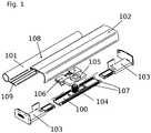
- eine schematische Explosionsdarstellung eines Teils einer Tür nach einer Ausführungsform der Erfindung mit einem Befestigungsprofil und einem Abdeckprofil;
- Fig. 2
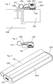
- eine schematische Schnittansicht eines Ausschnitts einer Tür nach einer Ausführungsform der Erfindung mit einem Türflügel, an dem der Teil aus
Fig. 1 befestigt ist; - Fig. 3
- eine schematische Schnittansicht des Teils aus
Fig. 1 ; - Fig. 4
- eine schematische perspektivische Darstellung des Teils aus
Fig. 1 ; - Fig. 5
- eine schematische Schnittdarstellung einer alternativen Ausführungsform der Erfindung, bei der das Abdeckprofil direkt über einen Abstandsverstellungsmechanismus am Befestigungsprofil befestigt ist;
- Fig. 6
- eine schematische Schnittansicht des Abdeckprofils aus
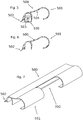
Fig. 5 ; und - Fig. 7
- eine schematische perspektivische Ansicht des Abdeckprofils aus
Fig. 5 mit einem herausgebrochenen Teilbereich.
- Fig. 1
- a schematic exploded view of part of a door according to an embodiment of the invention with a fastening profile and a cover profile;
- Fig. 2
- a schematic sectional view of a section of a door according to an embodiment of the invention with a door leaf on which the part from
Fig. 1 is attached; - Fig. 3
- a schematic sectional view of the part from FIG
Fig. 1 ; - Fig. 4
- a schematic perspective view of the part from
Fig. 1 ; - Fig. 5
- a schematic sectional view of an alternative embodiment of the invention, in which the cover profile is attached directly to the fastening profile via a distance adjustment mechanism;
- Fig. 6
- a schematic sectional view of the cover profile
Fig. 5 ; and - Fig. 7
- a schematic perspective view of the cover profile from
Fig. 5 with a broken out section.
Die Tür umfasst ein Befestigungsprofil 100, ein Abdeckprofil 101, ein Deckelprofil 102, zwei Endkappen 103, ein erstes Befestigungselement 104 mit einem Außengewinde, ein zweites Befestigungselement 105 mit einem Innengewinde und ein Verbindungselement 106. Das Befestigungsprofil 100 weist an seinen Seiten jeweils eine Schiene 107 auf, deren Längsachsen sich in Längsrichtung des Befestigungsprofils 100 erstrecken. Das Abdeckprofil 101 weist einen Bandabschnitt 108 und einen Verbindungsabschnitt 109 auf.The door comprises a
Das Befestigungsprofil 100 ist an einem Türflügel 202 befestigt, der über das Türband 200 schwenkbar an einer Türzarge 201 befestigt ist. Dies ist jedoch lediglich beispielhaft. Es ist auch eine Befestigung des Befestigungsprofils 100 an der Türzarge 201 möglich. Die Endkappen sind am Befestigungsprofil 100 befestigt, indem sie zwischen den Schienen 107 eingeschoben sind. Das erste Befestigungselement 104 ist ebenfalls zwischen den Schienen eingeschoben und so am Befestigungsprofil 100 befestigt. Das zweite Befestigungselement 105 ist mit dem Verbindungselement 106 verbunden, beispielsweise stoffschlüssig. Es ist auch möglich, dass das zweite Befestigungselement 105 und das Verbindungselement 106 einstückig und/oder einteilig ausgebildet sind.The
Das Verbindungselement 106 weist eine Stützfläche auf, mit der es am Befestigungsprofil 100 abgestützt ist. So wird einer Kippbewegung des Verbindungselements 106 während einer Öffnungsbewegung des Türflügels 202 entgegengewirkt.The connecting
Das zweite Befestigungselement 105 ist auf dem ersten Befestigungselement 104 aufgeschraubt. Der Verbindungsabschnitt 109 des Abdeckprofils 101 ist zwischen zwei Schenkeln des Verbindungselements 106 angeordnet und befestigt. Je nach dem, wie weit das zweite Befestigungselement 105 auf das erste Befestigungselement 104 aufgeschraubt wird, lässt sich somit ein Abstand des Abdeckprofils 101 vom Türflügel 202 in einer Richtung senkrecht zu einer der Hauptoberflächen des Türflügels 202 einstellen. Die Kombination aus dem ersten Befestigungselement 104 und dem zweiten Befestigungselement 105 kann daher auch als Abstandsverstellungsmechanismus bezeichnet werden.The
Der Bandabschnitt 108 weist eine kreisförmige Querschnittsfläche auf, deren Durchmesser an einen Durchmesser des Türbands 200 angepasst ist.The
Das Deckelprofil 102 ist am Befestigungsprofil 100 und/oder an den Endkappen 103 befestigt. Es deckt das Befestigungsprofil 100, einen ersten Teil des Verbindungsabschnitts 109, den Abstandsverstellungsmechanismus 104 und 105 und das Verbindungselement 106 ab. Das Deckelprofil 102 begrenzt zusammen mit den Endkappen 103 und dem Befestigungsprofil 100 einen Innenraum, in dem der Abstandsverstellungsmechanismus 104 und 105 und das Verbindungselement 106 angeordnet sind.The
Ein zweiter Teil des Verbindungsabschnitts 109 und der Bandabschnitt 108 ragen seitlich aus dem Innenraum heraus. Dabei ragt der zweite Teil des Verbindungsabschnitt 109 durch eine Öffnung zwischen dem Befestigungsprofil 100 und dem Deckelprofil 102.A second part of the connecting
Im am Türflügel 202 befestigten Zustand des Befestigungsprofils 100 ist der Abstand des Abdeckprofils 101 in senkrechter Richtung zu den Hauptoberflächen des Türflügels 202 so eingestellt, dass der Bandabschnitt 108 mit dem Türband 200 fluchtet. Ein Spalt zwischen der Türzarge 201 und dem Türblatt wird somit durch das Abdeckprofil 101 zumindest teilweise abgedeckt, sodass ein menschlicher Finger, beispielsweise ein Finger eines Kindes, nicht in diesen bandseitigen Spalt gesteckt werden kann. Da das Abdeckprofil 101 zudem in den Innenraum hineinragt und mit dem Befestigungsprofil 100 verbunden ist, wird auch aus einer seitlichen Richtung ein zuverlässiger Fingerschutz erreicht.When the
Die Position des Abdeckprofils 101 kann außerdem auch durch eine Wahl der Befestigungsposition des Befestigungsprofils 100 am Türflügel 202 sowohl in einer horizontalen Richtung parallel zu den Hauptoberflächen des Türflügels 202 und in vertikaler Richtung an die Position des Türbands 200 angepasst werden.The position of the
Außerdem kann das Verbindungselement 106 innerhalb der Schienen 107 in vertikaler Richtung frei verschoben werden. Dies beeinflusst auch die vertikale Position des Abdeckprofils 101. Dies ist insbesondere vorteilhaft, um für eine Befestigung des Befestigungsprofils 100 am Türflügel 202 benötigte Befestigungsbereich so anordnen zu können, dass sie bei der Montage nicht mit Befestigungsbereichen für das Türband 200 am Türflügel 202 kollidieren. Wenn beispielsweise sowohl das Türband 200 als auch das Befestigungsprofil 100 mit einer Schraubverbindung am Türflügel 202 befestigt werden, können die jeweiligen Schrauben im und am Türflügel 202 sich nicht kreuzen.In addition, the connecting
Im am Türflügel 202 oder an der Türzarge 201 montierten Zustand ist der komplette im Querschnitt kreisförmige Bandabschnitt 108 in einer horizontalen Richtung parallel zu den Hauptoberflächen des Türblatts 202 vom Befestigungsprofil 100 beabstandet. Dies hat insbesondere den Vorteil, dass der Fingerschutzmechanismus besonders flach ausgestaltet werden kann. Außerdem kann das Befestigungsprofil 100 beispielsweise am Türflügel 202 befestigt werden, auch wenn das Türband 200 in der horizontalen Richtung parallel zu den Hauptoberflächen des Türflügels 202 vom Türflügel 202 beabstandet ist.In the mounted state on the
Es ist möglich, dass ein Kabel aus dem Innenraum herausragt. Das Kabel kann beispielsweise seitlich rausragen und durch eine Ausnehmung im Bandabschnitt 108 in einen vom Bandabschnitt 108 umgebenen Raum geführt sein. Dieses Kabel kann beispielsweise genutzt werden, um ein elektrisch betriebenes Gerät im Innenraum mit elektrischem Strom zu versorgen und/oder um Sensordaten von einem im Innenraum angeordneten Sensor zu leiten.It is possible that a cable protrudes from the interior. The cable can, for example, protrude laterally and be guided through a recess in the
Bei der in
Das Abdeckprofil 500 weist außerdem eine Spaltabdeckung 502 auf, die auf einer vom Bandabschnitt 501 weg gerichteten Seite des Befestigungsprofils 100 angeordnet ist. Die Spaltabdeckung 502 ist elastisch verformbar und drückt gegen den Türflügel 202, wenn das Befestigungsprofil 100 am Türflügel 202 befestigt ist. Wenn das Befestigungsprofil 100 an der Türzarge 201 befestigt ist, drückt die Spaltabdeckung 502 gegen die Türzarge 201. Die Spaltabdeckung 502 erstreckt sich über die gesamte Länge des Abdeckprofils 501. Die Spaltabdeckung 502 begrenzt gemeinsam mit dem sich daran anschließenden Abschnitt des Abdeckprofils 500 und dem Befestigungsprofil 100 den Innenraum, in dem der Abstandsverstellungsmechanismus 503 angeordnet ist. Die Spaltabdeckung 502 deckt einen eventuell in Abhängigkeit vom Abstand des Abdeckprofils 500 vom Befestigungsprofil 100 entstehenden Spalt zwischen dem Abdeckprofil 500 und dem Befestigungsprofil 100 ab.The
Auch mit der Ausführungsform aus den
Das Abdeckprofil 504 weist eine Brechnut 504 auf, deren Längsachse parallel zur Längsachse des Abdeckprofils 500 verläuft. Die Brechnut 504 befindet sich dabei angrenzend zum Bandabschnitt 501.The
Bei der Montage des Abdeckprofils 500 kann somit ein Teilbereich des Bandabschnitts 501 im Bereich des Türbands 200 herausgebrochen werden, der durch die Brechnut 504 und zwei mit einem Schneidwerkzeug eingebrachten Einschnitten definiert ist. Auf diese Weise entsteht ein Freiraum 700, in dem im an der Tür montierten Zustand des Abdeckprofils 500 das Türband 200 angeordnet ist.During the assembly of the
Auch bei der Ausführungsform aus den
Die Ausführungsform der
Claims (15)
Priority Applications (1)
| Application Number | Priority Date | Filing Date | Title |
|---|---|---|---|
| EP20213516.6A EP3783178B1 (en) | 2020-12-11 | 2020-12-11 | Door |
Applications Claiming Priority (1)
| Application Number | Priority Date | Filing Date | Title |
|---|---|---|---|
| EP20213516.6A EP3783178B1 (en) | 2020-12-11 | 2020-12-11 | Door |
Publications (3)
| Publication Number | Publication Date |
|---|---|
| EP3783178A2 true EP3783178A2 (en) | 2021-02-24 |
| EP3783178A3 EP3783178A3 (en) | 2021-06-23 |
| EP3783178B1 EP3783178B1 (en) | 2024-03-20 |
Family
ID=73834344
Family Applications (1)
| Application Number | Title | Priority Date | Filing Date |
|---|---|---|---|
| EP20213516.6A Active EP3783178B1 (en) | 2020-12-11 | 2020-12-11 | Door |
Country Status (1)
| Country | Link |
|---|---|
| EP (1) | EP3783178B1 (en) |
Citations (1)
| Publication number | Priority date | Publication date | Assignee | Title |
|---|---|---|---|---|
| DE202014101362U1 (en) | 2014-03-24 | 2015-06-26 | Athmer Ohg | Device for covering a band-side gap between a door and a door frame |
Family Cites Families (3)
| Publication number | Priority date | Publication date | Assignee | Title |
|---|---|---|---|---|
| DE102017100587A1 (en) * | 2017-01-13 | 2018-07-19 | Athmer Ohg | Attachment of a finger protection roller blind for gap coverage |
| DE102019100645A1 (en) * | 2019-01-11 | 2020-07-16 | Hörmann Kg Ichtershausen | Pinch protection system for fencing and / or building closures, arrangement with pinch protection system, as well as fencing and / or building closures |
| EP3767067A1 (en) * | 2019-07-15 | 2021-01-20 | ASSA ABLOY (Schweiz) AG | Hinge-sided finger protection device |
-
2020
- 2020-12-11 EP EP20213516.6A patent/EP3783178B1/en active Active
Patent Citations (1)
| Publication number | Priority date | Publication date | Assignee | Title |
|---|---|---|---|---|
| DE202014101362U1 (en) | 2014-03-24 | 2015-06-26 | Athmer Ohg | Device for covering a band-side gap between a door and a door frame |
Also Published As
| Publication number | Publication date |
|---|---|
| EP3783178B1 (en) | 2024-03-20 |
| EP3783178A3 (en) | 2021-06-23 |
Similar Documents
| Publication | Publication Date | Title |
|---|---|---|
| DE3532650C2 (en) | ||
| EP1568833B1 (en) | Striker plate for a window or a door | |
| EP0035143B1 (en) | Hinge fitting for all-glass doors | |
| EP1709267B1 (en) | Clip fixing element for rapid assembly of fixture devices such as swivel lever locks, hinge parts in openings in a thin wall | |
| EP3258044B1 (en) | Wing assembly and method for head-on mounting of a fitting element in such a wing assembly | |
| EP3103948A1 (en) | Hinge for a door or a window | |
| EP3425155B1 (en) | Finger guard for a door | |
| EP0478639B1 (en) | Hinge | |
| DE3540766A1 (en) | ADJUSTABLE DOOR OR WINDOW TAPE | |
| DE202016106504U1 (en) | Assembly tool for mounting a cabinet door to a cabinet housing and a corresponding cabinet assembly | |
| DE4313610A1 (en) | Display device for a turn-tilt sash | |
| EP3783178B1 (en) | Door | |
| EP2565351A2 (en) | Handle assembly | |
| EP3875728B1 (en) | Profile connector assembly and frame comprising a profiled connector assembly | |
| EP1777363B1 (en) | Stop device for a door of a housing | |
| EP1560996B1 (en) | Mounting arrangement for glass doors | |
| EP3168394B1 (en) | Block for a door opener or a strike plate | |
| EP2740872B1 (en) | Corner bearing for concealed assembly | |
| DE3922995A1 (en) | Vertically sliding door with horizontal panels | |
| EP1344478B1 (en) | Shower cubicle with at least one glass partition wall | |
| DE3145375C2 (en) | Multi-part frame profile | |
| EP3759303A1 (en) | Mounting bracket for guide rails | |
| DE2460943A1 (en) | FURNITURE HINGE | |
| EP3786405A1 (en) | Furniture drive for moving a movable furniture part | |
| EP3556977B1 (en) | Frame member for a furniture frame and furniture |
Legal Events
| Date | Code | Title | Description |
|---|---|---|---|
| PUAI | Public reference made under article 153(3) epc to a published international application that has entered the european phase |
Free format text: ORIGINAL CODE: 0009012 |
|
| STAA | Information on the status of an ep patent application or granted ep patent |
Free format text: STATUS: THE APPLICATION HAS BEEN PUBLISHED |
|
| AK | Designated contracting states |
Kind code of ref document: A2 Designated state(s): AL AT BE BG CH CY CZ DE DK EE ES FI FR GB GR HR HU IE IS IT LI LT LU LV MC MK MT NL NO PL PT RO RS SE SI SK SM TR |
|
| AX | Request for extension of the european patent |
Extension state: BA ME |
|
| RIN1 | Information on inventor provided before grant (corrected) |
Inventor name: HECKMANN, ANDRE |
|
| PUAL | Search report despatched |
Free format text: ORIGINAL CODE: 0009013 |
|
| AK | Designated contracting states |
Kind code of ref document: A3 Designated state(s): AL AT BE BG CH CY CZ DE DK EE ES FI FR GB GR HR HU IE IS IT LI LT LU LV MC MK MT NL NO PL PT RO RS SE SI SK SM TR |
|
| RIC1 | Information provided on ipc code assigned before grant |
Ipc: E05D 5/04 20060101AFI20210520BHEP Ipc: E05D 11/00 20060101ALI20210520BHEP Ipc: E06B 7/36 20060101ALI20210520BHEP |
|
| STAA | Information on the status of an ep patent application or granted ep patent |
Free format text: STATUS: REQUEST FOR EXAMINATION WAS MADE |
|
| 17P | Request for examination filed |
Effective date: 20211223 |
|
| RBV | Designated contracting states (corrected) |
Designated state(s): AL AT BE BG CH CY CZ DE DK EE ES FI FR GB GR HR HU IE IS IT LI LT LU LV MC MK MT NL NO PL PT RO RS SE SI SK SM TR |
|
| STAA | Information on the status of an ep patent application or granted ep patent |
Free format text: STATUS: EXAMINATION IS IN PROGRESS |
|
| 17Q | First examination report despatched |
Effective date: 20220429 |
|
| GRAP | Despatch of communication of intention to grant a patent |
Free format text: ORIGINAL CODE: EPIDOSNIGR1 |
|
| STAA | Information on the status of an ep patent application or granted ep patent |
Free format text: STATUS: GRANT OF PATENT IS INTENDED |
|
| INTG | Intention to grant announced |
Effective date: 20231006 |
|
| GRAS | Grant fee paid |
Free format text: ORIGINAL CODE: EPIDOSNIGR3 |
|
| GRAA | (expected) grant |
Free format text: ORIGINAL CODE: 0009210 |
|
| STAA | Information on the status of an ep patent application or granted ep patent |
Free format text: STATUS: THE PATENT HAS BEEN GRANTED |
|
| AK | Designated contracting states |
Kind code of ref document: B1 Designated state(s): AL AT BE BG CH CY CZ DE DK EE ES FI FR GB GR HR HU IE IS IT LI LT LU LV MC MK MT NL NO PL PT RO RS SE SI SK SM TR |
|
| REG | Reference to a national code |
Ref country code: GB Ref legal event code: FG4D Free format text: NOT ENGLISH |
|
| REG | Reference to a national code |
Ref country code: CH Ref legal event code: EP |
|
| REG | Reference to a national code |
Ref country code: DE Ref legal event code: R096 Ref document number: 502020007397 Country of ref document: DE |
|
| REG | Reference to a national code |
Ref country code: IE Ref legal event code: FG4D Free format text: LANGUAGE OF EP DOCUMENT: GERMAN |