EP3781820B1 - Strukturierte gashaltende oberflächen - Google Patents
Strukturierte gashaltende oberflächen Download PDFInfo
- Publication number
- EP3781820B1 EP3781820B1 EP19720061.1A EP19720061A EP3781820B1 EP 3781820 B1 EP3781820 B1 EP 3781820B1 EP 19720061 A EP19720061 A EP 19720061A EP 3781820 B1 EP3781820 B1 EP 3781820B1
- Authority
- EP
- European Patent Office
- Prior art keywords
- gas
- liquid
- structured surface
- water
- layer
- Prior art date
- Legal status (The legal status is an assumption and is not a legal conclusion. Google has not performed a legal analysis and makes no representation as to the accuracy of the status listed.)
- Active
Links
Images


Classifications
-
- B—PERFORMING OPERATIONS; TRANSPORTING
- B08—CLEANING
- B08B—CLEANING IN GENERAL; PREVENTION OF FOULING IN GENERAL
- B08B17/00—Methods preventing fouling
- B08B17/02—Preventing deposition of fouling or of dust
- B08B17/06—Preventing deposition of fouling or of dust by giving articles subject to fouling a special shape or arrangement
- B08B17/065—Preventing deposition of fouling or of dust by giving articles subject to fouling a special shape or arrangement the surface having a microscopic surface pattern to achieve the same effect as a lotus flower
-
- B—PERFORMING OPERATIONS; TRANSPORTING
- B63—SHIPS OR OTHER WATERBORNE VESSELS; RELATED EQUIPMENT
- B63B—SHIPS OR OTHER WATERBORNE VESSELS; EQUIPMENT FOR SHIPPING
- B63B1/00—Hydrodynamic or hydrostatic features of hulls or of hydrofoils
- B63B1/32—Other means for varying the inherent hydrodynamic characteristics of hulls
- B63B1/34—Other means for varying the inherent hydrodynamic characteristics of hulls by reducing surface friction
- B63B1/36—Other means for varying the inherent hydrodynamic characteristics of hulls by reducing surface friction using mechanical means
-
- B—PERFORMING OPERATIONS; TRANSPORTING
- B63—SHIPS OR OTHER WATERBORNE VESSELS; RELATED EQUIPMENT
- B63B—SHIPS OR OTHER WATERBORNE VESSELS; EQUIPMENT FOR SHIPPING
- B63B1/00—Hydrodynamic or hydrostatic features of hulls or of hydrofoils
- B63B1/32—Other means for varying the inherent hydrodynamic characteristics of hulls
- B63B1/34—Other means for varying the inherent hydrodynamic characteristics of hulls by reducing surface friction
- B63B1/38—Other means for varying the inherent hydrodynamic characteristics of hulls by reducing surface friction using air bubbles or air layers gas filled volumes
-
- B—PERFORMING OPERATIONS; TRANSPORTING
- B63—SHIPS OR OTHER WATERBORNE VESSELS; RELATED EQUIPMENT
- B63B—SHIPS OR OTHER WATERBORNE VESSELS; EQUIPMENT FOR SHIPPING
- B63B59/00—Hull protection specially adapted for vessels; Cleaning devices specially adapted for vessels
- B63B59/04—Preventing hull fouling
- B63B59/045—Preventing hull fouling by wrapping the submerged hull or part of the hull with an impermeable sheet
-
- F—MECHANICAL ENGINEERING; LIGHTING; HEATING; WEAPONS; BLASTING
- F15—FLUID-PRESSURE ACTUATORS; HYDRAULICS OR PNEUMATICS IN GENERAL
- F15D—FLUID DYNAMICS, i.e. METHODS OR MEANS FOR INFLUENCING THE FLOW OF GASES OR LIQUIDS
- F15D1/00—Influencing flow of fluids
- F15D1/002—Influencing flow of fluids by influencing the boundary layer
- F15D1/0025—Influencing flow of fluids by influencing the boundary layer using passive means, i.e. without external energy supply
- F15D1/003—Influencing flow of fluids by influencing the boundary layer using passive means, i.e. without external energy supply comprising surface features, e.g. indentations or protrusions
- F15D1/0035—Influencing flow of fluids by influencing the boundary layer using passive means, i.e. without external energy supply comprising surface features, e.g. indentations or protrusions in the form of riblets
- F15D1/004—Influencing flow of fluids by influencing the boundary layer using passive means, i.e. without external energy supply comprising surface features, e.g. indentations or protrusions in the form of riblets oriented essentially parallel to the direction of flow
-
- F—MECHANICAL ENGINEERING; LIGHTING; HEATING; WEAPONS; BLASTING
- F15—FLUID-PRESSURE ACTUATORS; HYDRAULICS OR PNEUMATICS IN GENERAL
- F15D—FLUID DYNAMICS, i.e. METHODS OR MEANS FOR INFLUENCING THE FLOW OF GASES OR LIQUIDS
- F15D1/00—Influencing flow of fluids
- F15D1/002—Influencing flow of fluids by influencing the boundary layer
- F15D1/0065—Influencing flow of fluids by influencing the boundary layer using active means, e.g. supplying external energy or injecting fluid
- F15D1/008—Influencing flow of fluids by influencing the boundary layer using active means, e.g. supplying external energy or injecting fluid comprising fluid injection or suction means
-
- F—MECHANICAL ENGINEERING; LIGHTING; HEATING; WEAPONS; BLASTING
- F15—FLUID-PRESSURE ACTUATORS; HYDRAULICS OR PNEUMATICS IN GENERAL
- F15D—FLUID DYNAMICS, i.e. METHODS OR MEANS FOR INFLUENCING THE FLOW OF GASES OR LIQUIDS
- F15D1/00—Influencing flow of fluids
- F15D1/002—Influencing flow of fluids by influencing the boundary layer
- F15D1/0085—Methods of making characteristic surfaces for influencing the boundary layer
-
- Y—GENERAL TAGGING OF NEW TECHNOLOGICAL DEVELOPMENTS; GENERAL TAGGING OF CROSS-SECTIONAL TECHNOLOGIES SPANNING OVER SEVERAL SECTIONS OF THE IPC; TECHNICAL SUBJECTS COVERED BY FORMER USPC CROSS-REFERENCE ART COLLECTIONS [XRACs] AND DIGESTS
- Y02—TECHNOLOGIES OR APPLICATIONS FOR MITIGATION OR ADAPTATION AGAINST CLIMATE CHANGE
- Y02T—CLIMATE CHANGE MITIGATION TECHNOLOGIES RELATED TO TRANSPORTATION
- Y02T70/00—Maritime or waterways transport
- Y02T70/10—Measures concerning design or construction of watercraft hulls
Definitions
- the present invention relates to structured, gas-retaining surfaces for improving the friction-reducing properties of gas layers held under a liquid and for simultaneously suppressing turbulence.
- the present invention further relates to a device comprising this structured, gas-retaining surface and the use of this structured, gas-retaining surface.
- Corrosion - a phenomenon that is also largely related to the fact that the ship is in direct contact with the surrounding sea water with its high salinity.
- Fouling could also be avoided, as the sea plants, animals, algae and larvae would not reach the surface of the ship's hull due to the air layer.
- the air layer would serve as a "lubricating layer" for the ship, as the air layer has a much lower viscosity than water. This can reduce friction with the surrounding water.
- Air Microbubble Technology requires constant, uninterrupted pumping of air by a compressor. Conversely, this fact also makes it tolerant of air loss, which is inherent in this technology anyway.
- suitable measures must first be taken to regenerate the air layer.
- the present invention is therefore based on the object of providing a new approach to further improve the friction-reducing properties of surfaces which are in contact with a liquid or are to be brought into contact with it.
- a structured surface as defined in the appended claim 1 which has, at least in some areas, liquid-repellent structures on a liquid-facing side, which form a gas-retaining layer, wherein the liquid-repellent structures projections or protruding elements, wherein the surface of the gas-retaining layer has, at least in the region of the projections or protruding elements, a liquid-repellent surface which at least temporarily holds or can hold a gas layer under liquid, wherein the gas-retaining layer is divided into a plurality of self-contained compartments by fluid-impermeable partition walls, characterized in that the structured surface additionally has rib structures protruding parallel to the flow direction of the liquid or parallel to the direction of movement of the structured surface relative to the liquid, which are formed on the upper ends facing the liquid on the parts of the compartment walls which are aligned parallel to the flow direction, so that these compartment walls are raised in relation to the other compartment walls which are not aligned parallel to the flow direction and at least temporarily protrude
- the friction with the liquid can be significantly reduced due to the gas-retaining layer, since the viscosity of the retained gas layer is significantly lower than that of the liquid, for example in the form of water.
- the structured surface according to the invention has suitable protruding rib structures in addition to this surface structure, a suppression or reduction of turbulence can also be achieved, which further increases the friction-reducing effect of the surface without losing the anti-fouling effect and the anti-corrosive effect of the gas layer.
- These rib structures which are aligned largely parallel to the flow direction (where flow direction means the direction of relative movement between the surface and the surrounding liquid), are designed similarly to the riblet structures mentioned above and preferably end with a sharp edge, i.e. with an edge whose radius of curvature is significantly smaller than the width and height of the structure, ideally smaller by at least a factor of 10.
- the liquid which is at least partially in contact with the structured surface is any liquid.
- the liquid is preferably water, in particular fresh water or sea water, or an aqueous solution.
- the liquid can also contain alcohols, alkanes, oils, polar and non-polar solvents, without being limited to these. When reference is made to "water” below, this also includes the liquids mentioned above.
- the gas held in the gas-retaining layer may be, for example, air, nitrogen, argon, helium, carbon dioxide or another gas, with air, nitrogen, argon and helium being preferred.
- air when reference is made to "air” below, this also includes the gases mentioned above.
- the gas-retaining layer which is formed by the liquid-repellent structures, is designed in such a way that, when the structured surface according to the invention is used properly, a gas is retained by the gas-retaining layer.
- a body to which the structured surface according to the invention is applied is at least partially, preferably completely, separated from the liquid by the gas.
- the gas, which is retained by the gas-retaining layer, is fixed by the gas-retaining layer in such a way that it advantageously does not rise to the liquid surface or be carried away by a liquid flow.
- the gas-retaining layer may be as described in WO 2013/131618 A2 described gas-retaining surface cover, to which reference is made in full.
- the gas-retaining layer has projections or protruding elements on the side facing the liquid at least in some areas, the surface of the gas-retaining layer having a surface that repels the liquid at least in the area of the projections or protruding elements.
- the distance between the protruding elements is expediently dimensioned such that no liquid drops can arrange themselves between the protruding elements.
- the individual drops of liquid are advantageously carried by a large number of protruding elements, so that the interface between the liquid and the gas located between the protruding elements is essentially formed as an envelope of the protruding elements.
- the distance between two adjacent protruding elements can be about 50 ⁇ m to about 500 ⁇ m, preferably about 100 ⁇ m to about 200 ⁇ m.
- the gas-retaining layer is divided into a plurality of self-contained sub-areas (also called “compartments") by fluid-impermeable partition walls.
- the partition walls are preferably designed to be hydrophilic at least in some areas or completely or are provided with a hydrophilic surface at least in some areas or completely.
- a fluid is understood to mean a gas, a liquid and a mixture thereof. Consequently, the partition wall prevents a liquid flow or a gas flow from forming between adjacent sub-areas.
- the partition walls prevent gas from flowing away from one sub-area to the adjacent sub-area and thereby reducing the flow resistance. is increased locally compared to a contacting liquid and, in contrast, excess gas is released into the liquid from the part into which the gas flows.
- the partition walls can be formed in one piece or integrally together with the other elements of the gas-retaining layer.
- a plurality of hydrophobic protruding elements are located in a two-dimensional arrangement in each of the sub-regions of the gas-retaining layer.
- the projections or protruding elements preferably have a central surface area that is hydrophilic and that is surrounded by a hydrophobic surface area of the projections or protruding elements.
- the interface between the liquid and the gas is localized at the areas that are hydrophilic. This further advantageously prevents gas bubbles from being detached by a flow of the liquid.
- This local fixing of the gas-liquid boundary is also referred to as “pinning", so that the hydrophilic surface areas can also be referred to as "pinning centers”.
- the structured surface according to the invention preferably has the compartments described above in combination with the pinning centers described above.
- the aim of the surface structure according to the invention is therefore to avoid sharp edges and corners within the air-holding compartments and to maximize the radius of curvature, or more precisely, to keep the minimum radius of curvature occurring in the compartments as large as possible.
- this means using radii of curvature that are preferably not less than 10% of the length and 10% of the width of the compartment. This only affects the interior of the compartments and not their upper edge, which should exert as great an attraction on the water as possible (pinning) and for which sharp edges are expressly desired. And this expressly does not affect the rib or ribbed structures, for which a sharp edge at the upper end is also expressly desired, but rather it affects exclusively the air-holding interior of the compartments.
- the gas held in the gas-retaining layer can be, for example, air, nitrogen, argon, helium, carbon dioxide or another gas, with air, nitrogen, argon and helium being preferred.
- the gas is particularly preferably air or an air mixture with nitrogen, argon and/or helium.
- this retained gas layer does not contribute to a reduction in the formation of turbulence or only indirectly via the reduction of the interaction forces for example between the ship and the water. If these were zero, this would also prevent turbulence.
- the mere use of an air layer kept under water is not a direct measure for reducing turbulence.
- the structured surface therefore additionally has rib structures protruding parallel to the flow direction of the liquid or parallel to the direction of movement of the structured surface relative to the liquid to suppress or reduce turbulence, which protrude at least temporarily by 0.1 ⁇ m to 10 mm from the gas layer and into the liquid.
- These additional, protruding rib structures are preferably designed such that they protrude from the gas layer on the micrometer scale, i.e. from 0.1 ⁇ m to 100 ⁇ m, or on the millimeter scale, i.e. from 0.1 mm to 10 mm.
- These rib structures particularly preferably protrude at least 1 ⁇ m, more preferably at least 5 ⁇ m and particularly preferably at least 10 ⁇ m.
- rib structures can be designed in different ways and can, for example, have the cross-section of a rectangle, a triangle or a trapezoid. In any case, it is advantageous if the structures have as large an extension as possible in the longitudinal direction and taper towards the top with a radius of curvature of the edge in the range of 0.1 ⁇ m to 10 ⁇ m, particularly preferably between 1 ⁇ m and 8 ⁇ m.
- the structured surface is combined with a device which generates gas bubbles under liquid which are generated close to the gas layer of the structured surface held under liquid or which, as they rise from the Liquid may come close to or partially into contact with this gas layer.
- This device for generating the gas bubbles is not particularly limited and can be designed in the form of devices known in the prior art.
- This device is preferably designed such that the gas bubbles generated have a diameter of 10 ⁇ m to 10 mm, particularly preferably 10 ⁇ m to 1 mm, in particular 10 ⁇ m to 100 ⁇ m.
- the combination with the "Air Microbubble Technology”, i.e. by generating fine gas or air bubbles, for example under a ship or in the immediate vicinity of the ship's walls, can achieve the friction reduction through the gas or air layer with the additional friction reduction through the water diluted with gas or air bubbles in the immediate vicinity of the surface rubbing with the water.
- the material from which the structured surface is made can be selected depending on the application of the surface according to the invention. Preferably, however, a polymer material is used to manufacture the structured surface.
- the material of the structured surface contains at least one from the list consisting of silicones, silicone-based polymers and acrylic-based polymers.
- the additional protruding rib structures can be made of the same material as the gas-retaining layer of the structured surface itself.
- the protruding rib structures consist of a different material than the structured surface itself. Ceramic materials, oxides, metals or even steel are particularly suitable.
- the rib structures are not rigidly connected to the underlying structured surface. Instead, they are preferably designed to be flexible and movable. At least the protruding rib structures can be elastically connected to the underlying structured surface.
- the structured surface is preferably combined with a device that generates gas bubbles under liquid.
- the structured surface is able to capture the gas from the passing gas bubbles and in this way charge itself with gas or recharge lost gas.
- the structured surface can have additional second structures that protrude from the gas layer and extend into the liquid. These additional second structures can capture the gas from the passing gas bubbles in order to charge the gas layer with gas or to recharge lost gas.
- protruding second structures for the purpose of capturing air from the gas bubbles are present in addition to the actual protruding structures for suppressing or reducing turbulence, which are arranged parallel to the flow direction of the liquid or parallel to the direction of movement of the structured surface relative to the liquid.
- the structured surface is characterized in that the second structures protruding from the gas layer are elastic and stand upright without external forces and, in addition, at least in the part protruding into the liquid, are completely or partially designed by the wettability of their surface in such a way that they have liquid-repellent properties, wherein the elastic properties are adjusted in such a way that the structures can be partially or when the gas layer is completely lost, they stand up on their own and protrude into the liquid, where their liquid-repellent layers allow them to capture gas bubbles that recharge the gas layer, and as soon as a gas layer has formed again, they fold back into the gas layer due to their elastic and liquid-repellent properties.
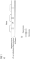
- the second structures protruding from the gas layer are aligned with the flow direction of the liquid or with the direction of movement of the structured surface relative to the liquid in such a way that they point obliquely backwards relative to the flow direction and/or are curved inwards in this direction (see Fig. 3 ).
- the existing underwater air-retaining layer is combined with a generator of gas bubbles (for example a compressor plus an outlet nozzle) and the ideally outward-sloping surface, for example of a ship that gets wider towards the top, comes into direct contact with the rising gas bubbles, which then integrate into the gas layer due to surface tension. This is a process that takes place voluntarily and releases energy in the process.
- a horizontal or almost horizontal surface such as the underside of the ship (depending on the shape of the ship's hull) can also come into direct contact with the gas bubbles generated under the ship's hull. In the latter case in particular, there is no restriction on the size of the gas bubbles.
- the gas bubble dissolves in the air layer as soon as it comes into direct contact with it.
- the capture is carried out by hydrophobic, elastic structures (hairs, nets, ribs) that are erected in air (without any water) and that are integrated into the underwater air-retaining layer and that initially protrude from the structured air-retaining layer due to their length and their angle relative to the surface, which should be flatter than 90°, i.e. flatter than a right angle, as shown schematically in Fig. 3(a) If you now put this layer under water, these hairs, because they are hydrophobic, will try to avoid contact with the water and because they are elastic, they will fold over and integrate into the air layer at a flatter angle, as shown in Fig.
- hydrophobic, elastic structures hairs, nets, ribs
- the advantage here is that if the air layer is charged and sufficiently thick, these air-trapping structures do not protrude into the water and therefore do not contribute to an increase in flow resistance. Only when air is lost, when the air layer becomes too thin, do the hairs fold out and capture air bubbles.
- the thickness of the air layer at which the hair folds out can be adjusted using the elastic properties of the structures (which can be adjusted directly in the case of the hair via shape and thickness).
- the great additional advantage of the combination is that all four effects, i.e. (i) the effect of the gas or air layer under water, (ii) the effect of directed structures to avoid or suppress turbulence near the ship's surface or another surface and (iii) the effect of reducing friction by introducing gas or air bubbles and (iv) the permanent or intermittent generation of gas or air bubbles in combination with structured, gas-retaining surfaces, the structures of which are designed in such a way that they allow gas bubbles to be captured from the water in the event of gas loss, can be achieved.
- the layer can recapture gas or air bubbles, which regenerate the gas or air layer.
- the present invention relates to a device comprising at least one of the surfaces according to the invention, wherein this is arranged between two plates and thereby forms a water layer and an air layer between the plates.
- This can also be done in the form of a stack in which at least two structured surfaces are arranged one above the other, in which gas and liquid layers alternate. This is particularly advantageous when large liquid surfaces are desired, for example to evaporate large amounts of liquid per unit time.
- gas-retaining surfaces under liquid Preferably, however, gas-permeable connections are made between the individual compartments.
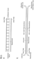
- the liquid itself also forms a layer, as is the case in the Figures 5(a) to 5(c) shown schematically.
- a glass, metal or plastic plate is used as the upper cover, onto which the underwater air-retaining structure is applied, for example with an air layer of between 0.1 mm and 5 mm thick, given by the height of the hydrophobic or superhydrophobic column structures with or without a hydrophilic end, which is located on the underside of the plate.
- another plate ideally of the same size, made of the same or a different material is placed, with the distance between the plates being greater than the thickness of the air-retaining layer, for example 0.1 mm to 30 mm greater, preferably 1 mm to 15 mm greater.
- the plates are now horizontal and the space between the plates is filled with water with no or only slight overpressure or underpressure (typically up to 30 mbar above or below the ambient air pressure), the water does not completely fill the space between the plates: the air-retaining layer remains on the top. Now you can slowly let water flow in and the water enriched with salts (the brine) is drawn off on the other side. At the same time, you pump air through the air-conducting layer above the water.
- not only two parallel, preferably horizontally positioned plates are used, between which there is a water-conducting layer (preferably at the bottom) and an air-conducting layer (preferably at the top), but several such plates are used, one on top of the other.
- the plate stack can be as thick as desired. Two plates are then no longer required per layer. One plate per layer is sufficient, with a contains a structured layer that holds air under water and does not have one on the top. If the distance between adjacent layers in the stack is, for example, 1 cm, then 100 square meters of water surface can be created in a volume of 1 cubic meter. This raises the question of how to transport the heat energy away. This can then no longer be done sufficiently by cooling the surface.
- a very simple variant of the above-mentioned device which is characterized by cost-effective production but very low stability, particularly in the case of fluctuations in water pressure and air pressure, is the use of unstructured or randomly structured plates with any surface. Even for plates that do not have a structured surface that retains air under water, a hydrophilic underside (where the water layer rests) and a hydrophobic or superhydrophobic top side (where contact with the air layer occurs) is an advantageous design of the device.
- the present invention also relates to the use of the structured surface according to the invention on ship surfaces, in plants for desalination of water or in plants for salt enrichment in salt production as well as in cooling systems as compact, high-performance cooling units.
- the structured surface according to the invention can be obtained from ship surfaces in particular (i) to reduce the frictional forces between the ship and the water, (ii) to prevent biofilm growth and fouling, (iii) to prevent corrosion and (iv) to prevent the release of toxic or environmentally harmful substances from the ship's coating into the surrounding water.
- the structured surface or device according to the invention can be used in particular for the production of process water and drinking water.
- the structured surface according to the invention can be used in particular using multi-layer systems of gas and underlying liquid, whereby the liquid evaporates into the gas layer and is discharged from it as a gas enriched or saturated with the molecules of the liquid ("vapor").
- vapor the molecules of the liquid
- the structured surface according to the invention can also be used in cooling systems as compact, high-performance cooling units for evaporating water or another liquid using evaporative cooling. This can preferably be in power plants.
Landscapes
- Engineering & Computer Science (AREA)
- Physics & Mathematics (AREA)
- Fluid Mechanics (AREA)
- Mechanical Engineering (AREA)
- General Engineering & Computer Science (AREA)
- Chemical & Material Sciences (AREA)
- Combustion & Propulsion (AREA)
- Ocean & Marine Engineering (AREA)
- Physical Or Chemical Processes And Apparatus (AREA)
- Laminated Bodies (AREA)
- Absorbent Articles And Supports Therefor (AREA)
Applications Claiming Priority (2)
| Application Number | Priority Date | Filing Date | Title |
|---|---|---|---|
| DE102018003141.2A DE102018003141B4 (de) | 2018-04-17 | 2018-04-17 | Strukturierte Oberfläche sowie Vorrichtung umfassend diese und deren Verwendung |
| PCT/EP2019/059294 WO2019201744A1 (de) | 2018-04-17 | 2019-04-11 | Strukturierte gashaltende oberflächen |
Publications (3)
| Publication Number | Publication Date |
|---|---|
| EP3781820A1 EP3781820A1 (de) | 2021-02-24 |
| EP3781820C0 EP3781820C0 (de) | 2024-10-23 |
| EP3781820B1 true EP3781820B1 (de) | 2024-10-23 |
Family
ID=66323817
Family Applications (1)
| Application Number | Title | Priority Date | Filing Date |
|---|---|---|---|
| EP19720061.1A Active EP3781820B1 (de) | 2018-04-17 | 2019-04-11 | Strukturierte gashaltende oberflächen |
Country Status (8)
| Country | Link |
|---|---|
| US (1) | US12000417B2 (https=) |
| EP (1) | EP3781820B1 (https=) |
| JP (2) | JP7376502B2 (https=) |
| KR (1) | KR102774400B1 (https=) |
| CN (1) | CN111989498B (https=) |
| CA (1) | CA3097076A1 (https=) |
| DE (1) | DE102018003141B4 (https=) |
| WO (1) | WO2019201744A1 (https=) |
Families Citing this family (4)
| Publication number | Priority date | Publication date | Assignee | Title |
|---|---|---|---|---|
| GB2602354B (en) * | 2020-12-24 | 2024-10-02 | Thales Holdings Uk Plc | A barrier component and a method of manufacturing a barrier component |
| US12097932B2 (en) * | 2022-11-22 | 2024-09-24 | Shipglide, Inc. | System and method for reducing drag on hulls of marine crafts thereby increasing fluid dynamic efficiencies |
| US12263914B2 (en) * | 2022-11-22 | 2025-04-01 | Airglide, AI. Inc | System and method for delivering air to a submerged ship surface |
| WO2026057741A1 (en) | 2024-09-12 | 2026-03-19 | Basf Coatings Gmbh | Composite material with a superhydrophobic surface and coating composition for superhydrophobic post-treatment of microstructured surfaces |
Family Cites Families (27)
| Publication number | Priority date | Publication date | Assignee | Title |
|---|---|---|---|---|
| DE3522943A1 (de) * | 1985-06-27 | 1987-01-08 | Messerschmitt Boelkow Blohm | Einrichtung zur verringerung des turbulenten reibungswiderstandes bei luft-, raum- und wasserfahrzeugen |
| DE3534268A1 (de) * | 1985-09-26 | 1987-04-02 | Deutsche Forsch Luft Raumfahrt | Zur vermeidung von stroemungsabloesungen ausgebildete oberflaeche eines umstroemten koerpers |
| GB8706554D0 (en) | 1987-03-19 | 1987-04-23 | Rolls Royce Plc | Boundary layer devices |
| US5090352A (en) * | 1987-02-24 | 1992-02-25 | Corwin R. Horton | Bow foil |
| WO1988007956A1 (en) | 1987-04-16 | 1988-10-20 | Allan Donald Thomas | Microbubble injection device for reducing the fluid frictional resistance against a vessel |
| GB8812494D0 (en) | 1988-05-26 | 1988-06-29 | British Maritime Technology Lt | Improvements in/relating to reduction of drag |
| JP2890340B2 (ja) | 1992-09-29 | 1999-05-10 | 三井造船株式会社 | 没水部分を有する構造物の没水表面に空気膜を形成する方法及び没水表面の膜体構造 |
| JPH1029587A (ja) * | 1996-07-12 | 1998-02-03 | Ishikawajima Harima Heavy Ind Co Ltd | 船舶の摩擦抵抗低減装置 |
| JP2000087921A (ja) * | 1998-09-18 | 2000-03-28 | Agency Of Ind Science & Technol | 流動抵抗低減方法 |
| GB0112857D0 (en) * | 2001-05-25 | 2001-07-18 | Anglia Polytechnic University | A heat exchanger |
| PL204021B1 (pl) * | 2001-11-02 | 2009-12-31 | Cnt Spo & Lstrok Ka Z Ogranicz | Powłoka superhydrofobowa |
| JP2003226867A (ja) | 2002-02-05 | 2003-08-15 | Asti Ltd Advanced Systems Of Technology Incubation | 易滑雪性固体およびその製造方法 |
| JP4257973B2 (ja) | 2003-07-30 | 2009-04-30 | 独立行政法人産業技術総合研究所 | 流動抵抗の低減方法及び装置 |
| US20060251859A1 (en) * | 2005-05-05 | 2006-11-09 | D Urso Brian R | Friction drag-reducing surface |
| CN201159217Y (zh) * | 2008-02-14 | 2008-12-03 | 李冬庆 | 液压通路冲油吸油装置 |
| WO2009122736A1 (ja) | 2008-04-01 | 2009-10-08 | 独立行政法人海上技術安全研究所 | 船舶の摩擦抵抗低減装置 |
| JP2009247949A (ja) | 2008-04-03 | 2009-10-29 | Toshiba Corp | 撥水性コーティング皮膜及び液体輸送配管 |
| US8632843B2 (en) | 2008-11-24 | 2014-01-21 | Promimic Ab | Methods and systems of controlled coating of nanoparticles onto micro-rough implant surfaces and associated implants |
| KR20100076439A (ko) | 2008-12-26 | 2010-07-06 | 부산대학교 산학협력단 | 고체표면에 마이크로 기포 형성방법 |
| US7997221B2 (en) | 2009-03-23 | 2011-08-16 | Dan Nicolaus Costas | Apparatus for reducing drag on a nautical vessel |
| KR101788833B1 (ko) | 2010-06-04 | 2017-10-20 | 삼성전자 주식회사 | 초소수성 그라펜 및 그의 제조방법 |
| KR101906613B1 (ko) | 2010-07-27 | 2018-10-10 | 더 리전트 오브 더 유니버시티 오브 캘리포니아 | 액체에서 초소수성을 회복하고 유지하기 위한 방법 및 장치 |
| DE102011121796A1 (de) | 2010-12-21 | 2012-08-16 | Rheinische Friedrich-Wilhelms-Universität Bonn | Unbenetzbare Oberflächen |
| CA2866082C (en) * | 2012-03-03 | 2021-06-22 | Baden-Wurttemberg Stiftung Ggmbh | Use of a gas-retaining layer which is arranged on a body that is immersible in a liquid or wettable by the liquid |
| KR102378963B1 (ko) * | 2014-07-18 | 2022-03-24 | 더 리전트 오브 더 유니버시티 오브 캘리포니아 | 침수된 표면의 미세 형상 속 기체 유지 장치 및 방법 |
| WO2017115694A1 (ja) | 2015-12-28 | 2017-07-06 | シャープ株式会社 | 光学部材、及び、光学部材の製造方法 |
| DE102018105394A1 (de) | 2018-03-08 | 2019-09-12 | Karlsruher Institut für Technologie | Analysepartikel und Verfahren zur Quantifizierung von porösen Materialien |
-
2018
- 2018-04-17 DE DE102018003141.2A patent/DE102018003141B4/de active Active
-
2019
- 2019-04-11 KR KR1020207029984A patent/KR102774400B1/ko active Active
- 2019-04-11 EP EP19720061.1A patent/EP3781820B1/de active Active
- 2019-04-11 CA CA3097076A patent/CA3097076A1/en active Pending
- 2019-04-11 JP JP2020556767A patent/JP7376502B2/ja active Active
- 2019-04-11 WO PCT/EP2019/059294 patent/WO2019201744A1/de not_active Ceased
- 2019-04-11 US US16/982,321 patent/US12000417B2/en active Active
- 2019-04-11 CN CN201980026256.0A patent/CN111989498B/zh active Active
-
2023
- 2023-10-26 JP JP2023183702A patent/JP7715782B2/ja active Active
Also Published As
| Publication number | Publication date |
|---|---|
| EP3781820C0 (de) | 2024-10-23 |
| CN111989498B (zh) | 2023-01-03 |
| BR112020021199A8 (pt) | 2023-02-07 |
| US20210033119A1 (en) | 2021-02-04 |
| JP2021521390A (ja) | 2021-08-26 |
| JP7376502B2 (ja) | 2023-11-08 |
| WO2019201744A1 (de) | 2019-10-24 |
| EP3781820A1 (de) | 2021-02-24 |
| DE102018003141B4 (de) | 2019-11-07 |
| BR112020021199A2 (pt) | 2021-01-19 |
| KR20210002491A (ko) | 2021-01-08 |
| KR102774400B1 (ko) | 2025-03-04 |
| CA3097076A1 (en) | 2019-10-24 |
| US12000417B2 (en) | 2024-06-04 |
| JP2024012381A (ja) | 2024-01-30 |
| CN111989498A (zh) | 2020-11-24 |
| DE102018003141A1 (de) | 2019-10-17 |
| JP7715782B2 (ja) | 2025-07-30 |
Similar Documents
| Publication | Publication Date | Title |
|---|---|---|
| EP3781820B1 (de) | Strukturierte gashaltende oberflächen | |
| EP2822704B1 (de) | Gashaltende oberflächenabdeckung, anordnung und verwendung | |
| EP3436757B1 (de) | Klimatisierung durch mehrphasen-plattenwärmetauscher | |
| DE3005192C2 (de) | Membran für die thermische Destillation | |
| EP2919966B1 (de) | Verfahren zur herstellung eines formkörpers mit superhydrophober oberfläche | |
| Guo et al. | Surfaces and interfaces of biomimetic superhydrophobic materials | |
| Xiao et al. | Sandwiched copper foam with symmetrical wettability for direction-independent fog collection | |
| Ding et al. | Bionic surfaces for fog collection: A comprehensive review of natural organisms and bioinspired strategies | |
| DE102010034152A1 (de) | Vorrichtung zur Gewinnung von Wasser aus atmosphärischer Luft | |
| WO2023083640A1 (de) | Kapillarsogverdampfungseinrichtung | |
| DE4029071C2 (de) | Vorrichtung zum Verdampfen von flüssigen Produkten, Verfahren zum Betreiben der Vorrichtung sowie Verwendung der Vorrichtung als Dampferzeuger oder Kondensator | |
| EP3912964B1 (de) | Vorrichtung zur entsalzung von meerwasser und ein verfahren zum betrieb der vorrichtung | |
| DE102018129328A1 (de) | Meerwasserentsalzungsanlage und Verfahren zum Gewinnen von Süßwasser aus Meerwasser | |
| DE102011007292A1 (de) | Anlage zur Entsalzung von salzhaltigem Roh- bzw. Brauchwasser | |
| Wei | Passive Atmospheric Water Harvesting: Bioinspired Designs & Thermo-Responsive Hydrogels | |
| DE102012208941A1 (de) | Eisspeicher mit verbessertem Wärmetauscher | |
| DE102009030770A1 (de) | Verfahren und Vorrichtung zur Herstellung von Trinkwasser mit Sonnenenergie und Anwendung eines Membranverfahrens | |
| Abu Draz | PREPARATION OF COPPER OXIDE NANO-ARCHITECTURES FOR FOG HARVESTING APPLICATIONS | |
| DE102016123512A1 (de) | Verdampfervorrichtung | |
| DE1671920C3 (de) | Verfahren und Vorrichtung zur gemeinsamen Abführung von Verlustwärme und Reaktionswasser aus Brennstoffelementen oder Brennstoffbatterien | |
| DE10258912B4 (de) | Wasserstrahlkerze als Luftbefeuchter | |
| DE102021001243A1 (de) | System zur Beeinflussung der Meeresspiegelhöhe | |
| Traverso | Kommunismus–ein Ortstermin. | |
| DE102007024671A1 (de) | Wasseraufbereitungsanlage | |
| WO2006045261A1 (de) | Wärmetauscher zur wassergewinnung |
Legal Events
| Date | Code | Title | Description |
|---|---|---|---|
| STAA | Information on the status of an ep patent application or granted ep patent |
Free format text: STATUS: UNKNOWN |
|
| STAA | Information on the status of an ep patent application or granted ep patent |
Free format text: STATUS: THE INTERNATIONAL PUBLICATION HAS BEEN MADE |
|
| PUAI | Public reference made under article 153(3) epc to a published international application that has entered the european phase |
Free format text: ORIGINAL CODE: 0009012 |
|
| STAA | Information on the status of an ep patent application or granted ep patent |
Free format text: STATUS: REQUEST FOR EXAMINATION WAS MADE |
|
| 17P | Request for examination filed |
Effective date: 20201029 |
|
| AK | Designated contracting states |
Kind code of ref document: A1 Designated state(s): AL AT BE BG CH CY CZ DE DK EE ES FI FR GB GR HR HU IE IS IT LI LT LU LV MC MK MT NL NO PL PT RO RS SE SI SK SM TR |
|
| AX | Request for extension of the european patent |
Extension state: BA ME |
|
| DAV | Request for validation of the european patent (deleted) | ||
| DAX | Request for extension of the european patent (deleted) | ||
| STAA | Information on the status of an ep patent application or granted ep patent |
Free format text: STATUS: EXAMINATION IS IN PROGRESS |
|
| 17Q | First examination report despatched |
Effective date: 20230428 |
|
| GRAP | Despatch of communication of intention to grant a patent |
Free format text: ORIGINAL CODE: EPIDOSNIGR1 |
|
| STAA | Information on the status of an ep patent application or granted ep patent |
Free format text: STATUS: GRANT OF PATENT IS INTENDED |
|
| INTG | Intention to grant announced |
Effective date: 20240516 |
|
| GRAS | Grant fee paid |
Free format text: ORIGINAL CODE: EPIDOSNIGR3 |
|
| GRAA | (expected) grant |
Free format text: ORIGINAL CODE: 0009210 |
|
| STAA | Information on the status of an ep patent application or granted ep patent |
Free format text: STATUS: THE PATENT HAS BEEN GRANTED |
|
| AK | Designated contracting states |
Kind code of ref document: B1 Designated state(s): AL AT BE BG CH CY CZ DE DK EE ES FI FR GB GR HR HU IE IS IT LI LT LU LV MC MK MT NL NO PL PT RO RS SE SI SK SM TR |
|
| REG | Reference to a national code |
Ref country code: GB Ref legal event code: FG4D Free format text: NOT ENGLISH |
|
| REG | Reference to a national code |
Ref country code: CH Ref legal event code: EP |
|
| REG | Reference to a national code |
Ref country code: DE Ref legal event code: R096 Ref document number: 502019012347 Country of ref document: DE |
|
| REG | Reference to a national code |
Ref country code: IE Ref legal event code: FG4D Free format text: LANGUAGE OF EP DOCUMENT: GERMAN |
|
| U01 | Request for unitary effect filed |
Effective date: 20241112 |
|
| U07 | Unitary effect registered |
Designated state(s): AT BE BG DE DK EE FI FR IT LT LU LV MT NL PT RO SE SI Effective date: 20241120 |
|
| PG25 | Lapsed in a contracting state [announced via postgrant information from national office to epo] |
Ref country code: IS Free format text: LAPSE BECAUSE OF FAILURE TO SUBMIT A TRANSLATION OF THE DESCRIPTION OR TO PAY THE FEE WITHIN THE PRESCRIBED TIME-LIMIT Effective date: 20250223 Ref country code: HR Free format text: LAPSE BECAUSE OF FAILURE TO SUBMIT A TRANSLATION OF THE DESCRIPTION OR TO PAY THE FEE WITHIN THE PRESCRIBED TIME-LIMIT Effective date: 20241023 |
|
| PG25 | Lapsed in a contracting state [announced via postgrant information from national office to epo] |
Ref country code: ES Free format text: LAPSE BECAUSE OF FAILURE TO SUBMIT A TRANSLATION OF THE DESCRIPTION OR TO PAY THE FEE WITHIN THE PRESCRIBED TIME-LIMIT Effective date: 20241023 |
|
| PG25 | Lapsed in a contracting state [announced via postgrant information from national office to epo] |
Ref country code: NO Free format text: LAPSE BECAUSE OF FAILURE TO SUBMIT A TRANSLATION OF THE DESCRIPTION OR TO PAY THE FEE WITHIN THE PRESCRIBED TIME-LIMIT Effective date: 20250123 |
|
| PG25 | Lapsed in a contracting state [announced via postgrant information from national office to epo] |
Ref country code: GR Free format text: LAPSE BECAUSE OF FAILURE TO SUBMIT A TRANSLATION OF THE DESCRIPTION OR TO PAY THE FEE WITHIN THE PRESCRIBED TIME-LIMIT Effective date: 20250124 |
|
| PG25 | Lapsed in a contracting state [announced via postgrant information from national office to epo] |
Ref country code: PL Free format text: LAPSE BECAUSE OF FAILURE TO SUBMIT A TRANSLATION OF THE DESCRIPTION OR TO PAY THE FEE WITHIN THE PRESCRIBED TIME-LIMIT Effective date: 20241023 |
|
| PG25 | Lapsed in a contracting state [announced via postgrant information from national office to epo] |
Ref country code: RS Free format text: LAPSE BECAUSE OF FAILURE TO SUBMIT A TRANSLATION OF THE DESCRIPTION OR TO PAY THE FEE WITHIN THE PRESCRIBED TIME-LIMIT Effective date: 20250123 |
|
| U20 | Renewal fee for the european patent with unitary effect paid |
Year of fee payment: 7 Effective date: 20250429 |
|
| PG25 | Lapsed in a contracting state [announced via postgrant information from national office to epo] |
Ref country code: SM Free format text: LAPSE BECAUSE OF FAILURE TO SUBMIT A TRANSLATION OF THE DESCRIPTION OR TO PAY THE FEE WITHIN THE PRESCRIBED TIME-LIMIT Effective date: 20241023 |
|
| PG25 | Lapsed in a contracting state [announced via postgrant information from national office to epo] |
Ref country code: SK Free format text: LAPSE BECAUSE OF FAILURE TO SUBMIT A TRANSLATION OF THE DESCRIPTION OR TO PAY THE FEE WITHIN THE PRESCRIBED TIME-LIMIT Effective date: 20241023 |
|
| PG25 | Lapsed in a contracting state [announced via postgrant information from national office to epo] |
Ref country code: CZ Free format text: LAPSE BECAUSE OF FAILURE TO SUBMIT A TRANSLATION OF THE DESCRIPTION OR TO PAY THE FEE WITHIN THE PRESCRIBED TIME-LIMIT Effective date: 20241023 |
|
| PLBE | No opposition filed within time limit |
Free format text: ORIGINAL CODE: 0009261 |
|
| STAA | Information on the status of an ep patent application or granted ep patent |
Free format text: STATUS: NO OPPOSITION FILED WITHIN TIME LIMIT |
|
| 26N | No opposition filed |
Effective date: 20250724 |
|
| REG | Reference to a national code |
Ref country code: CH Ref legal event code: H13 Free format text: ST27 STATUS EVENT CODE: U-0-0-H10-H13 (AS PROVIDED BY THE NATIONAL OFFICE) Effective date: 20251125 |
|
| PG25 | Lapsed in a contracting state [announced via postgrant information from national office to epo] |
Ref country code: MC Free format text: LAPSE BECAUSE OF FAILURE TO SUBMIT A TRANSLATION OF THE DESCRIPTION OR TO PAY THE FEE WITHIN THE PRESCRIBED TIME-LIMIT Effective date: 20241023 |
|
| GBPC | Gb: european patent ceased through non-payment of renewal fee |
Effective date: 20250411 |
|
| PG25 | Lapsed in a contracting state [announced via postgrant information from national office to epo] |
Ref country code: GB Free format text: LAPSE BECAUSE OF NON-PAYMENT OF DUE FEES Effective date: 20250411 |
|
| PG25 | Lapsed in a contracting state [announced via postgrant information from national office to epo] |
Ref country code: CH Free format text: LAPSE BECAUSE OF NON-PAYMENT OF DUE FEES Effective date: 20250430 |
|
| PG25 | Lapsed in a contracting state [announced via postgrant information from national office to epo] |
Ref country code: IE Free format text: LAPSE BECAUSE OF NON-PAYMENT OF DUE FEES Effective date: 20250411 |