EP3780353B1 - Motorstator, motor und bus - Google Patents
Motorstator, motor und bus Download PDFInfo
- Publication number
- EP3780353B1 EP3780353B1 EP19863129.3A EP19863129A EP3780353B1 EP 3780353 B1 EP3780353 B1 EP 3780353B1 EP 19863129 A EP19863129 A EP 19863129A EP 3780353 B1 EP3780353 B1 EP 3780353B1
- Authority
- EP
- European Patent Office
- Prior art keywords
- tooth
- tooth crest
- stator
- crest part
- motor
- Prior art date
- Legal status (The legal status is an assumption and is not a legal conclusion. Google has not performed a legal analysis and makes no representation as to the accuracy of the status listed.)
- Active
Links
Images




Classifications
-
- H—ELECTRICITY
- H02—GENERATION; CONVERSION OR DISTRIBUTION OF ELECTRIC POWER
- H02K—DYNAMO-ELECTRIC MACHINES
- H02K1/00—Details of the magnetic circuit
- H02K1/06—Details of the magnetic circuit characterised by the shape, form or construction
- H02K1/12—Stationary parts of the magnetic circuit
- H02K1/17—Stator cores with permanent magnets
-
- H—ELECTRICITY
- H02—GENERATION; CONVERSION OR DISTRIBUTION OF ELECTRIC POWER
- H02K—DYNAMO-ELECTRIC MACHINES
- H02K3/00—Details of windings
- H02K3/46—Fastening of windings on the stator or rotor structure
- H02K3/48—Fastening of windings on the stator or rotor structure in slots
- H02K3/487—Slot-closing devices
-
- H—ELECTRICITY
- H02—GENERATION; CONVERSION OR DISTRIBUTION OF ELECTRIC POWER
- H02K—DYNAMO-ELECTRIC MACHINES
- H02K1/00—Details of the magnetic circuit
- H02K1/06—Details of the magnetic circuit characterised by the shape, form or construction
- H02K1/12—Stationary parts of the magnetic circuit
- H02K1/14—Stator cores with salient poles
- H02K1/146—Stator cores with salient poles consisting of a generally annular yoke with salient poles
- H02K1/148—Sectional cores
-
- H—ELECTRICITY
- H02—GENERATION; CONVERSION OR DISTRIBUTION OF ELECTRIC POWER
- H02K—DYNAMO-ELECTRIC MACHINES
- H02K1/00—Details of the magnetic circuit
- H02K1/06—Details of the magnetic circuit characterised by the shape, form or construction
- H02K1/12—Stationary parts of the magnetic circuit
- H02K1/16—Stator cores with slots for windings
- H02K1/165—Shape, form or location of the slots
-
- H—ELECTRICITY
- H02—GENERATION; CONVERSION OR DISTRIBUTION OF ELECTRIC POWER
- H02K—DYNAMO-ELECTRIC MACHINES
- H02K21/00—Synchronous motors having permanent magnets; Synchronous generators having permanent magnets
- H02K21/12—Synchronous motors having permanent magnets; Synchronous generators having permanent magnets with stationary armatures and rotating magnets
- H02K21/22—Synchronous motors having permanent magnets; Synchronous generators having permanent magnets with stationary armatures and rotating magnets with magnets rotating around the armatures, e.g. flywheel magnetos
-
- H—ELECTRICITY
- H02—GENERATION; CONVERSION OR DISTRIBUTION OF ELECTRIC POWER
- H02K—DYNAMO-ELECTRIC MACHINES
- H02K21/00—Synchronous motors having permanent magnets; Synchronous generators having permanent magnets
- H02K21/26—Synchronous motors having permanent magnets; Synchronous generators having permanent magnets with rotating armatures and stationary magnets
-
- H—ELECTRICITY
- H02—GENERATION; CONVERSION OR DISTRIBUTION OF ELECTRIC POWER
- H02K—DYNAMO-ELECTRIC MACHINES
- H02K2201/00—Specific aspects not provided for in the other groups of this subclass relating to the magnetic circuits
- H02K2201/03—Machines characterised by aspects of the air-gap between rotor and stator
-
- H—ELECTRICITY
- H02—GENERATION; CONVERSION OR DISTRIBUTION OF ELECTRIC POWER
- H02K—DYNAMO-ELECTRIC MACHINES
- H02K2213/00—Specific aspects, not otherwise provided for and not covered by codes H02K2201/00 - H02K2211/00
- H02K2213/03—Machines characterised by numerical values, ranges, mathematical expressions or similar information
-
- Y—GENERAL TAGGING OF NEW TECHNOLOGICAL DEVELOPMENTS; GENERAL TAGGING OF CROSS-SECTIONAL TECHNOLOGIES SPANNING OVER SEVERAL SECTIONS OF THE IPC; TECHNICAL SUBJECTS COVERED BY FORMER USPC CROSS-REFERENCE ART COLLECTIONS [XRACs] AND DIGESTS
- Y02—TECHNOLOGIES OR APPLICATIONS FOR MITIGATION OR ADAPTATION AGAINST CLIMATE CHANGE
- Y02T—CLIMATE CHANGE MITIGATION TECHNOLOGIES RELATED TO TRANSPORTATION
- Y02T10/00—Road transport of goods or passengers
- Y02T10/60—Other road transportation technologies with climate change mitigation effect
- Y02T10/64—Electric machine technologies in electromobility
Definitions
- the present disclosure relates to the technical field of motors, and in particular to a motor stator, a motor and a bus.
- Low-speed, high-torque motors apply to various occasions, for example, electric vehicles, high-speed trains, elevators, mines and the like.
- motors have a large number of poles, and corresponding a number of stator slots increased exponentially, causing difficulties of processing and craft.
- a near-polar-slot permanent magnet synchronous motor is an ideal low-speed, large-torque motor, because the number of its stator slots is close to the number of the rotor poles. Therefore, the near-polar-slot permanent magnet synchronous motor is adapted to resolve the foregoing problem.
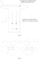
- a tooth crest 1' of a stator of a near-polar-slot permanent magnet synchronous motor is relatively wider, approaching the length of the polar arc of a rotor.
- a considerable part of the flux linkages generated by the permanent magnet directly close when passing the tooth crest 1' of the stator, and passes the magnetic flux leakage path 3' only, but does not pass the main magnetic flux path 2'.
- the part of the flux linkages will not generate effective torque, and therefore reduces the utilization rate of the permanent magnet.
- Magnetic flux leakage at the tooth crest of the stator further enables the tooth crest of the stator to become saturated in an early stage, further weakening the torque output of the motor.
- torque pulsation also increases.
- the magnetic flux leakage at the tooth crest is caused by the tooth crest of the stator closing to the polar arc of the rotor, the magnetic flux leakage of the magnetic field at the tooth crest of the stator just closes when passing the tooth crest, and does not pass the yoke portion Magnetic flux leakage at the tooth crest will result in side effects such as a low utilization rate to the permanent magnet, early saturation to the tooth crest of the motor and large torque pulsation.
- DE102010038764A1 relates to an electrical machine 1 comprising a cylindrical stator 2 with inwardly directed stator teeth 3. At an inboard end of the stator teeth 3, tooth tips 5 are provided. The tooth tip is provided with grooves 14.
- DE102016220823A1 relates to a stator 10 that is provided with stator teeth 32.
- the stator tooth 32 is provided with a slot 36.
- the slot 36 extends from the inner circumference 42 outward toward the outer circumference 40.
- DE202016102217U1 relates to a stator that is provided with tooth bodies 22 and tooth tips.
- the magnetic bridges 38 connect the tooth tips 24 to a unit, so that these together form a closed annular edge.
- DE102010002696A1 relates to a stator 1 that includes stator teeth 14 and tooth tips 5.
- the stator teeth 14 are provided with a slot.
- the end of the tooth tip 5 is insert into the slot.
- each segmented tooth tip portion 42 includes three tooth tips 40.
- the segmented tooth tip portions 42 can include any number of tooth tips 40.
- the tooth tips 40 in each of the segmented tooth tip portions 42 are coupled together by a bridge portion 44.
- the segmented tooth tip portions 42 are mounted to the stator teeth 34 following winding of the coils.
- the segmented tooth tip portions 42 are mounted to the stator teeth 34 by any suitable means.
- CN202978459U relates to a motor comprising a stator and a rotor.
- the stator is located at the periphery of the rotor.
- the stator is formed by splicing tooth blocks in the tooth slots.
- the top of one tooth block is provided with an adjustment slot.
- the rotor is formed by 20 pieces of magnetic steel alternately bonded on the yoke by the yoke and NS pole.
- the technical problem to be resolved by the present disclosure is to provide a motor stator, a motor and a bus, which can reduce magnetic flux leakage, and enhance the utilization rate of a permanent magnet and output torque.
- the present disclosure provides a motor stator, including a stator tooth, wherein the stator tooth includes a tooth root and a tooth crest; the tooth crest is provided on the tooth root; the tooth crest includes a first tooth crest part and a second tooth crest part; the first tooth crest part and the second tooth crest part are provided on two sides of the tooth root along the circumference of the motor stator, respectively, and a tooth crest air gap is formed between the first tooth crest part and the second tooth crest part.
- the tooth crest air gap radially penetrates through the first tooth crest part and the second tooth crest part, and separates the first tooth crest part from the second tooth crest part.
- the tooth crest air gap radially extends from ends, close to the tooth root, of the first tooth crest part and the second tooth crest part, and the first tooth crest part and the second tooth crest part abut at ends away from the tooth root, so as to close the tooth crest air gap.
- first tooth crest part and the second tooth crest part are integrally molded.
- the first tooth crest part of the stator tooth abuts the second tooth crest part of an adjoining stator tooth to form a closed slot.
- first tooth crest part of the stator tooth and the second tooth crest part of the adjoining stator tooth are integrally molded.
- the first tooth crest part and the second tooth crest part are in a clamped fixation with the tooth root.
- the tooth root is provided with a first clamping slot which extends along an axis direction of the motor stator, and the first tooth crest part is clamped in the first clamping slot; and/or, the tooth root is provided with a second clamping slot which extends along the axis direction of the motor stator, and the second tooth crest part is clamped in the second clamping slot.
- the cross section of the first clamping slot and/or the second clamping slot is trapezoidal, -shaped or major arc shaped.
- a length of the tooth crest air gap is L 1 , 0.2 ⁇ L T ⁇ L 1 ⁇ 0.4 ⁇ L T ;
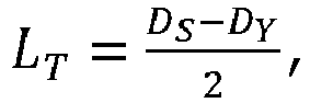
- L T D S ⁇ D Y 2 wherein D S is an outer diagram of the stator, and Dy is a bottom diameter of the slot of the stator.
- the tooth crest is made of an oriented silicon steel sheet.
- a motor including a motor stator, where the motor stator is the forgoing motor stator.
- a bus including the foregoing motor stator.
- the motor stator provided by the present disclosure includes the stator tooth; the stator tooth includes the tooth root and the tooth crest; the tooth crest is provided on the tooth root; the tooth crest includes the first tooth crest part and the second tooth crest part; the first tooth crest part and the second tooth crest part are provided on two sides of the tooth root along the circumference of the motor stator, respectively, and the tooth crest air gap is formed between the first tooth crest part and the second tooth crest part .
- the tooth crest of the stator tooth is treated, such that the tooth crest is divided into the first tooth crest part and the second tooth crest part, and that the first tooth crest part and the second tooth crest part form the tooth crest air gap there-between.
- the magnetic resistance of the tooth crest air gap is far greater than that of a stator core, the magnetic field generated by a permanent magnet on a rotor bypasses the tooth crest air gap when passing a stator tooth, and returns to the permanent magnet via a stator yoke portion, forming a closed circuit.
- the magnetic flux leakage to be closed by a magnetic flux leakage path is changed into the main magnetic flux to be closed by a main magnetic flux path, fulfilling the purposes of reducing magnetic flux leakage and enhancing the utilization rate of the permanent magnet and the output torque.
- the present disclosure lowers the saturation degree of the tooth crest of the stator tooth, and enhances the working performance of the motor.
- Magnetic flux leakage referring to a magnetic field in the motor closed, but not pass through the main magnetic flux path, will not generate effective torque but result in that a part of a core where the magnetic flux leakage passes becomes saturated.
- Main magnetic flux path a magnetic field generated by a permanent magnet of a rotor passes an air gap, a stator tooth portion, a stator yoke portion, a stator tooth portion and an air gap, and then returns to the rotor and closes.
- the aforementioned magnetic channel is the main magnetic flux path, and is a path of magnetic field closing in the normal operating state of the motor.
- Magnetic flux leakage path a magnetic flux path to which a magnetic field does not pass the main magnetic flux path, but directly closes.
- a motor stator includes a stator tooth 1; the stator tooth 1 includes a tooth root 2 and a tooth crest 3; the tooth crest 3 is provided on the tooth root 2; the tooth crest 3 includes a first tooth crest part 4 and a second tooth crest part 5; the first tooth crest part 4 and the second tooth crest part 5 are provided on two sides of the tooth root 2 along the circumference of the motor stator, respectively, and a tooth crest air gap 6 is formed between the first tooth crest part 4 and the second tooth crest part 5.
- the tooth crest air gap 6 forms an air gap between the first tooth crest part 4 and the second tooth crest part 5, is adapt to separate at least part of the first tooth crest part 4 and the second tooth crest part 5.
- the tooth crest 3 of the stator tooth 1 is treated, such that the tooth crest 3 is divided into the first tooth crest part 4 and the second tooth crest part 5, and that the first tooth crest part 4 and the second tooth crest part 5 form the tooth crest air gap 6 there-between. Since the magnetic resistance of the tooth crest air gap 6 is far greater than that of a stator core, the magnetic field generated by a permanent magnet on a rotor bypasses the tooth crest air gap 6 when passing a stator tooth 1, and returns to the permanent magnet via a stator yoke portion, forming a closed circuit.
- the magnetic flux leakage to be closed by a magnetic flux leakage path is changed into the main magnetic flux to be closed by a main magnetic flux path, fulfilling the purposes of reducing magnetic flux leakage and enhancing the utilization rate of the permanent magnet and the output torque.
- the present disclosure lowers the saturation degree of the tooth crest of the stator tooth, and enhances the working performance of the motor.
- the foregoing motor stator is for example a stator of a near-polar-slot permanently magnetic synchronous motor.
- the tooth crest of the stator of the near-polar-slot permanent magnet synchronous motor is halved such that each of the stator teeth has two smaller tooth crest parts. Decreasing the width of the tooth crest is equal to increasing the tangential (magnetic flux leakage direction) magnetic resistance of the tooth crest, while increasing the magnetic resistance is adapted to effectively bring a decline in the magnetic flux leakage to this part.
- the tooth crest air gap 6 is designed between the two tooth crest parts, and the magnetic resistance of the tooth crest air gap 6 is higher, so as to lead a smaller magnetic flux leakage at the tooth crest furtherly.
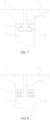
- the tooth crest air gap 6 radially penetrates through the first tooth crest part 4 and the second tooth crest part 5 and separates the first tooth crest part 4 from the second tooth crest part 5, as shown in FIG. 3 and FIG. 4 .
- the first tooth crest part 4 and the second tooth crest part 5 are completely separated by the tooth crest air gap 6; the tooth crest air gap 6 is adopted to entirely block the magnetic flux leakage at the tooth crest, further to enhance the utilization rate of the permanent magnet and the output torque.
- the tooth crest air gap 6 radially extends from ends, close to the tooth root 2, of the first tooth crest part 4 and the second tooth crest part 5, and the first tooth crest part 4 and the second tooth crest part 5 abut at ends away from the tooth root 2, so as to close the tooth crest air gap 6, as shown in FIG. 6 .
- the top portion of the first tooth crest part 4 extends to form a protrusion towards the second tooth crest part 5; the top portion of the second tooth crest part 5 extends to form a protrusion towards the first tooth crest part 4; the two protrusions abut to close a top opening of the tooth crest air gap 6, so as to forme a closed tooth crest air gap 6.
- stator surface achieves a surface without slot opening, thereby resulting in smoother change of the magnetic resistance at the air gap between the rotor and the stator and bringing a smaller torque pulsation.
- first tooth crest part 4 and the second tooth crest part 5 are integrally molded to generate higher structure performance.
- the first tooth crest part 4 and the second tooth crest part 5 are also suitable for fixedly connecting as a whole by means of splicing.
- the first tooth crest part 4 of the stator tooth 1 abuts the second tooth crest part 5 of an adjoining stator tooth 1 to form a closed slot, as shown in FIG. 5 and FIG. 6 .
- the tops of two half stator teeth between two adjacent stator teeth 1 are jointed, which means that the first tooth crest part 4 of one stator tooth 1 is jointed with the second tooth crest part 5 of the other stator tooth 1, thereby forming a combined tooth crest part of stator.
- the combined tooth crest part of stator is in a fastened connection with the tooth root 2 by snap-fit to form the stator tooth crest of a near-polar-slot permanently magnetic synchronous motor.
- the jointed stator tooth crest seals the slot opening of the stator to form a closed slot.
- the connection by snap-fit allows the operation of inserting a coil first and then sealing off the tooth crest for the motor, thereby resolving the problem that it is difficult to insert a coil in the closed slot.
- the stator undergoing the jointing treatment has the closed slot, and combining with the halving treatment decreases the saturation degree of of the tooth crest of the stator, such that the magnetic resistance at the air gap between the stator and the rotor changes smoothly, thereby optimizing the magnetic intensity waveform at the air gap and obviously reducing the torque pulse, as shown in FIG. 13 .
- the first tooth crest part 4 of the stator tooth 1 and the second tooth crest part 5 of an adjoining stator tooth 1 are integrally molded.
- the first tooth crest part 4 and the second tooth crest part 5 are in separate clamped fixations with the tooth root 2, the fitting difficultyof the first tooth crest part 4 and the second tooth crest part 5 with the tooth root 2 is reduced, and the processing cost is reduced.
- the tooth root 2 is provided with a first clamping slot 7 which extends along an axis direction of the motor stator, and the first tooth crest part 4 is clamped in the first clamping slot 7; and/or, the tooth root 2 is provided with a second clamping slot 8 which extends along the axis direction of the motor stator, and the second tooth crest part 5 is clamped in the second clamping slot 8.
- the first clamping slot 7 and the second clamping slot 8 have the same structure to improve the structural symmetry between the first tooth crest part 4 and the second tooth crest part 5.
- the first tooth crest part 4 and the second tooth crest part 5 on the tooth root 2 are symmetrically arranged with regard to the axial plane of the tooth root 2, and the first clamping slot 7 and the second clamping slot 8 are also symmetric to the plane, thereby reducing the processing difficutly and cost of the first tooth crest part 4 and the second tooth crest part 5, reducing the number of molds, and lowering the cost of mold opening.
- the cross section of the first clamping slot 7 and/or the second clamping slot 8 is trapezoidal, or major arc shaped.
- the cross section of the first clamping slot 7 and/or the second clamping slot 8 is of another shape, for example a dovetail or sector shape.
- a length of the tooth crest air gap 6 is L 1 , 0.2 ⁇ L T ⁇ L 1 ⁇ 0.4 ⁇ L T ;
- L T D S ⁇ D Y 2 wherein D S is the outer diagram of the stator, and D Y is a bottom diameter of the slot of the stator.
- the tooth crest 3 is made of oriented silicon steel sheets.
- the motor includes a motor stator, and the motor stator is the forgoing motor stator.
- the motor stator is optionally a stator of a near-polar-slot permanently magnetic synchronous motor.
- a bus includes the forgoing motor stator.
Landscapes
- Engineering & Computer Science (AREA)
- Power Engineering (AREA)
- Iron Core Of Rotating Electric Machines (AREA)
Claims (11)
- Motorständer, der einen Ständerzahn (1) aufweist, wobei der Ständerzahn (1) einen Zahnfuß (2) und eine Zahnspitze (3) aufweist; die Zahnspitze (3) an dem Zahnfuß (2) bereitgestellt ist; die Zahnspitze (3) einen ersten Zahnspitzenteil (4) und einen zweiten Zahnspitzenteil (5) aufweist; der erste Zahnspitzenteil (4) und der zweite Zahnspitzenteil (5) jeweilig an zwei Seiten des Zahnfußes (2) am Umfang des Motorständers entlang bereitgestellt sind und ein Zahnspitzenluftspalt (6) zwischen dem ersten Zahnspitzenteil (4) und dem zweiten Zahnspitzenteil gebildet ist,wobei der Zahnspitzenluftspalt (6) den ersten Zahnspitzenteil (4) und den zweiten Zahnspitzenteil (5) radial durchdringt und den ersten Zahnspitzenteil (4) vom zweiten Zahnspitzenteil (5) trennt; undder erste Zahnspitzenteil (4) des Ständerzahns (1) und der zweite Zahnspitzenteil (5) des angrenzenden Ständerzahns (1) integral geformt sind;dadurch gekennzeichnet, dassder erste Zahnspitzenteil (4) und der zweite Zahnspitzenteil (5) sich in separaten geklemmten Befestigungen mit dem Zahnfuß (2) befinden.
- Motorständer nach Anspruch 1, wobei der Zahnspitzenluftspalt (6) sich radial von Enden, nahe an dem Zahnfuß (2), des ersten Zahnspitzenteils (4) und des zweiten Zahnspitzenteils (5) erstreckt und der erste Zahnspitzenteil (4) und der zweite Zahnspitzenteil (5) an von dem Zahnfuß (2) entfernten Enden aneinanderstoßen, um den Zahnspitzenluftspalt (6) zu schließen.
- Motorständer nach Anspruch 2, wobei der erste Zahnspitzenteil (4) und der zweite Zahnspitzenteil (5) integral geformt sind.
- Motorständer nach Anspruch 1, wobei der erste Zahnspitzenteil (4) des Ständerzahns (1) am zweiten Zahnspitzenteil (5) eines angrenzenden Ständerzahns (1) in Anlage ist, so dass ein geschlossener Schlitz gebildet wird.
- Motorständer nach einem der Ansprüche 1 bis 4, wobei der Zahnfuß (2) mit einer ersten Einspannnut (7) versehen ist, die sich entlang einer Achsrichtung des Motorständers erstreckt, und der erste Zahnspitzenteil (4) in der ersten Einspannnut (7) eingespannt ist; und/oder der Zahnfuß (2) mit einer zweiten Einspannnut (8) versehen ist, die sich entlang der Achsrichtung des Motorständers erstreckt, und der zweite Zahnspitzenteil (5) in der zweiten Einspannnut (8) eingeklemmt ist.
- Motorständer nach Anspruch 5, wobei der Querschnitt der ersten Einspannnut (7) und/oder der zweiten Einspannnut (8) trapezförmig ist oder die Form eines Kreisbogens von mehr als 180° hat.
- Motorständer nach einem der Ansprüche 1 bis 4, wobei in einem Querschnitt, der senkrecht zu einer Mittelachse des Motorständers verläuft, eine Breite des Zahnspitzenluftspaltes (6) W1 ist,


- Motorständer nach einem der Ansprüche 1 bis 4, wobei in einem Querschnitt, der senkrecht zu einer Mittelachse des Motorständers verläuft, eine Länge des Zahnspitzenluftspaltes (6) L1 ist,

- Motorständer nach einem der Ansprüche 1 bis 4, wobei die Zahnspitze (3) aus kornorientiertem Siliziumstahlblech hergestellt ist.
- Motor, der den Motorständer nach einem der Ansprüche 1 bis 9 aufweist.
- Bus, der den Motorständer nach einem der Ansprüche 1 bis 9 aufweist.
Applications Claiming Priority (2)
| Application Number | Priority Date | Filing Date | Title |
|---|---|---|---|
| CN201811090914.6A CN109120080B (zh) | 2018-09-19 | 2018-09-19 | 电机定子、电机和大巴 |
| PCT/CN2019/070659 WO2020057018A1 (zh) | 2018-09-19 | 2019-01-07 | 电机定子、电机和大巴 |
Publications (3)
| Publication Number | Publication Date |
|---|---|
| EP3780353A1 EP3780353A1 (de) | 2021-02-17 |
| EP3780353A4 EP3780353A4 (de) | 2021-08-18 |
| EP3780353B1 true EP3780353B1 (de) | 2024-10-30 |
Family
ID=64859736
Family Applications (1)
| Application Number | Title | Priority Date | Filing Date |
|---|---|---|---|
| EP19863129.3A Active EP3780353B1 (de) | 2018-09-19 | 2019-01-07 | Motorstator, motor und bus |
Country Status (4)
| Country | Link |
|---|---|
| US (1) | US11575290B2 (de) |
| EP (1) | EP3780353B1 (de) |
| CN (1) | CN109120080B (de) |
| WO (1) | WO2020057018A1 (de) |
Families Citing this family (2)
| Publication number | Priority date | Publication date | Assignee | Title |
|---|---|---|---|---|
| CN109120080B (zh) * | 2018-09-19 | 2024-09-20 | 珠海格力电器股份有限公司 | 电机定子、电机和大巴 |
| CN111478462A (zh) * | 2019-01-24 | 2020-07-31 | 福特全球技术公司 | 用于电机的定子及其制造方法 |
Family Cites Families (20)
| Publication number | Priority date | Publication date | Assignee | Title |
|---|---|---|---|---|
| JPH08126273A (ja) * | 1994-08-30 | 1996-05-17 | Honda Motor Co Ltd | リラクタンスモータ |
| JP2000023397A (ja) * | 1998-07-07 | 2000-01-21 | Shibaura Mechatronics Corp | モータの固定子コア及びそれを用いるモータの製造方法 |
| US6091168A (en) * | 1998-12-22 | 2000-07-18 | Hamilton Sundstrand Corporation | Rotor for a dynamoelectric machine |
| JP2006060894A (ja) * | 2004-08-18 | 2006-03-02 | Sumitomo Electric Ind Ltd | 圧粉磁心部品およびその製造方法、圧粉磁心およびその製造方法、ならびに成形型 |
| FR2931317B1 (fr) * | 2008-05-19 | 2010-09-17 | Jeumont Electric | Rotor d'une machine electrique synchrone multipolaire a poles saillants |
| DE102008042100A1 (de) * | 2008-09-15 | 2010-03-18 | Brose Fahrzeugteile GmbH & Co. Kommanditgesellschaft, Würzburg | Permanentmagnet-Synchronmotor und elektrische Servolenkung |
| DE102010002696A1 (de) * | 2009-09-03 | 2011-03-10 | Robert Bosch Gmbh | Stator mit separat gefertigten Zahnköpfen |
| US8410656B2 (en) * | 2009-10-30 | 2013-04-02 | General Electric Company | Segmented stator assembly |
| DE102010038764A1 (de) * | 2010-08-02 | 2012-02-02 | Robert Bosch Gmbh | Wicklungszahn und Komponente für eine elektrische Maschine zur Reduzierung von Wirbelströmen |
| WO2012032591A1 (ja) * | 2010-09-06 | 2012-03-15 | 三菱電機株式会社 | 永久磁石型回転電機及びそれを用いた電動パワーステアリング装置 |
| KR101514487B1 (ko) * | 2011-09-22 | 2015-04-22 | 삼성전기주식회사 | 스테이터 코어 및 이를 구비하는 스핀들 모터 |
| CN202978459U (zh) * | 2012-11-05 | 2013-06-05 | 贵州航天林泉电机有限公司 | 一种无刷力矩电机的定位转矩调试结构 |
| CN203225602U (zh) * | 2013-04-08 | 2013-10-02 | 上海日立电器有限公司 | 一种拼接式定子铁芯 |
| CN104600879A (zh) | 2015-02-06 | 2015-05-06 | 沈阳工业大学 | 基于有取向硅钢片的低速近极槽永磁电机的定子结构 |
| DE202016102217U1 (de) * | 2015-05-08 | 2016-07-22 | Johnson Electric S.A. | Einphasiger Außenläufermotor und Ständer desselben |
| CN204721115U (zh) * | 2015-07-06 | 2015-10-21 | 中国矿业大学 | 一种双转子径向磁场永磁电机的定子结构 |
| CN105322669A (zh) | 2015-11-17 | 2016-02-10 | 天津市天发重型水电设备制造有限公司 | 一种发电机定子铁心端部冲片的齿部开沟槽的改进结构 |
| DE102016220823A1 (de) * | 2016-10-24 | 2018-04-26 | Robert Bosch Gmbh | Stator mit in den Endbereichen verminderten Wirbelströmen |
| CN109120080B (zh) * | 2018-09-19 | 2024-09-20 | 珠海格力电器股份有限公司 | 电机定子、电机和大巴 |
| CN208835846U (zh) * | 2018-09-19 | 2019-05-07 | 珠海格力电器股份有限公司 | 电机定子、电机和大巴 |
-
2018
- 2018-09-19 CN CN201811090914.6A patent/CN109120080B/zh active Active
-
2019
- 2019-01-07 WO PCT/CN2019/070659 patent/WO2020057018A1/zh not_active Ceased
- 2019-01-07 EP EP19863129.3A patent/EP3780353B1/de active Active
- 2019-01-07 US US17/054,799 patent/US11575290B2/en active Active
Also Published As
| Publication number | Publication date |
|---|---|
| WO2020057018A1 (zh) | 2020-03-26 |
| US20210242742A1 (en) | 2021-08-05 |
| EP3780353A1 (de) | 2021-02-17 |
| EP3780353A4 (de) | 2021-08-18 |
| CN109120080B (zh) | 2024-09-20 |
| US11575290B2 (en) | 2023-02-07 |
| CN109120080A (zh) | 2019-01-01 |
Similar Documents
| Publication | Publication Date | Title |
|---|---|---|
| US10644550B2 (en) | Rotor for rotating electric machine | |
| EP3136559B1 (de) | Permanentmagnetsynchronmotor und rotor dafür | |
| US6847144B1 (en) | Permanent magnet rotor assembly for interior permanent magnet electric motor | |
| US20090261679A1 (en) | Rotating electrical machine | |
| JP2006014457A (ja) | 同期電動機 | |
| CN103026586A (zh) | 电动机用转子 | |
| US20170324311A1 (en) | Switched reluctance motor | |
| US10680475B2 (en) | Rotor for rotary electric machine | |
| EP3683932B1 (de) | Motorläufer | |
| WO2023240970A1 (zh) | 电机转子、电机和电动汽车 | |
| EP1643618A2 (de) | Rotor für rotierende elektrische Maschine | |
| CN110212666A (zh) | 转子冲片结构、定子冲片和电机结构 | |
| JP6507956B2 (ja) | 永久磁石式回転電機 | |
| US11575290B2 (en) | Motor stator with tooth crest air gap, motor and bus | |
| CN209358302U (zh) | 一种分段气隙的永磁无刷直流电机定转子冲片结构 | |
| CN110957830B (zh) | 电机转子、磁阻电机和电动汽车 | |
| CN112653274B (zh) | 转子冲片及永磁电机转子 | |
| JP7615913B2 (ja) | 回転電機 | |
| CN111711291B (zh) | 转子结构、电机及压缩机 | |
| JP2013066339A (ja) | 埋め込み磁石型回転電機 | |
| JP2000333390A (ja) | 永久磁石電動機 | |
| CN210123912U (zh) | 转子冲片结构、定子冲片和电机结构 | |
| JP2007097290A (ja) | 永久磁石型リラクタンス回転電機 | |
| CN208835846U (zh) | 电机定子、电机和大巴 | |
| CN205377493U (zh) | 新能源汽车用非对称型永磁电机 |
Legal Events
| Date | Code | Title | Description |
|---|---|---|---|
| STAA | Information on the status of an ep patent application or granted ep patent |
Free format text: STATUS: THE INTERNATIONAL PUBLICATION HAS BEEN MADE |
|
| PUAI | Public reference made under article 153(3) epc to a published international application that has entered the european phase |
Free format text: ORIGINAL CODE: 0009012 |
|
| STAA | Information on the status of an ep patent application or granted ep patent |
Free format text: STATUS: REQUEST FOR EXAMINATION WAS MADE |
|
| 17P | Request for examination filed |
Effective date: 20201103 |
|
| AK | Designated contracting states |
Kind code of ref document: A1 Designated state(s): AL AT BE BG CH CY CZ DE DK EE ES FI FR GB GR HR HU IE IS IT LI LT LU LV MC MK MT NL NO PL PT RO RS SE SI SK SM TR |
|
| AX | Request for extension of the european patent |
Extension state: BA ME |
|
| A4 | Supplementary search report drawn up and despatched |
Effective date: 20210719 |
|
| RIC1 | Information provided on ipc code assigned before grant |
Ipc: H02K 1/27 20060101AFI20210713BHEP Ipc: H02K 21/26 20060101ALI20210713BHEP Ipc: H02K 1/16 20060101ALI20210713BHEP Ipc: H02K 1/14 20060101ALI20210713BHEP |
|
| DAV | Request for validation of the european patent (deleted) | ||
| DAX | Request for extension of the european patent (deleted) | ||
| P01 | Opt-out of the competence of the unified patent court (upc) registered |
Effective date: 20230530 |
|
| GRAP | Despatch of communication of intention to grant a patent |
Free format text: ORIGINAL CODE: EPIDOSNIGR1 |
|
| STAA | Information on the status of an ep patent application or granted ep patent |
Free format text: STATUS: GRANT OF PATENT IS INTENDED |
|
| INTG | Intention to grant announced |
Effective date: 20240708 |
|
| GRAS | Grant fee paid |
Free format text: ORIGINAL CODE: EPIDOSNIGR3 |
|
| GRAA | (expected) grant |
Free format text: ORIGINAL CODE: 0009210 |
|
| STAA | Information on the status of an ep patent application or granted ep patent |
Free format text: STATUS: THE PATENT HAS BEEN GRANTED |
|
| AK | Designated contracting states |
Kind code of ref document: B1 Designated state(s): AL AT BE BG CH CY CZ DE DK EE ES FI FR GB GR HR HU IE IS IT LI LT LU LV MC MK MT NL NO PL PT RO RS SE SI SK SM TR |
|
| REG | Reference to a national code |
Ref country code: GB Ref legal event code: FG4D |
|
| REG | Reference to a national code |
Ref country code: CH Ref legal event code: EP |
|
| REG | Reference to a national code |
Ref country code: IE Ref legal event code: FG4D |
|
| REG | Reference to a national code |
Ref country code: DE Ref legal event code: R096 Ref document number: 602019061283 Country of ref document: DE |
|
| REG | Reference to a national code |
Ref country code: LT Ref legal event code: MG9D |
|
| REG | Reference to a national code |
Ref country code: NL Ref legal event code: MP Effective date: 20241030 |
|
| PG25 | Lapsed in a contracting state [announced via postgrant information from national office to epo] |
Ref country code: PT Free format text: LAPSE BECAUSE OF FAILURE TO SUBMIT A TRANSLATION OF THE DESCRIPTION OR TO PAY THE FEE WITHIN THE PRESCRIBED TIME-LIMIT Effective date: 20250228 Ref country code: IS Free format text: LAPSE BECAUSE OF FAILURE TO SUBMIT A TRANSLATION OF THE DESCRIPTION OR TO PAY THE FEE WITHIN THE PRESCRIBED TIME-LIMIT Effective date: 20250228 Ref country code: HR Free format text: LAPSE BECAUSE OF FAILURE TO SUBMIT A TRANSLATION OF THE DESCRIPTION OR TO PAY THE FEE WITHIN THE PRESCRIBED TIME-LIMIT Effective date: 20241030 |
|
| PG25 | Lapsed in a contracting state [announced via postgrant information from national office to epo] |
Ref country code: FI Free format text: LAPSE BECAUSE OF FAILURE TO SUBMIT A TRANSLATION OF THE DESCRIPTION OR TO PAY THE FEE WITHIN THE PRESCRIBED TIME-LIMIT Effective date: 20241030 Ref country code: NL Free format text: LAPSE BECAUSE OF FAILURE TO SUBMIT A TRANSLATION OF THE DESCRIPTION OR TO PAY THE FEE WITHIN THE PRESCRIBED TIME-LIMIT Effective date: 20241030 |
|
| REG | Reference to a national code |
Ref country code: AT Ref legal event code: MK05 Ref document number: 1737895 Country of ref document: AT Kind code of ref document: T Effective date: 20241030 |
|
| PG25 | Lapsed in a contracting state [announced via postgrant information from national office to epo] |
Ref country code: BG Free format text: LAPSE BECAUSE OF FAILURE TO SUBMIT A TRANSLATION OF THE DESCRIPTION OR TO PAY THE FEE WITHIN THE PRESCRIBED TIME-LIMIT Effective date: 20241030 |
|
| PG25 | Lapsed in a contracting state [announced via postgrant information from national office to epo] |
Ref country code: ES Free format text: LAPSE BECAUSE OF FAILURE TO SUBMIT A TRANSLATION OF THE DESCRIPTION OR TO PAY THE FEE WITHIN THE PRESCRIBED TIME-LIMIT Effective date: 20241030 |
|
| PG25 | Lapsed in a contracting state [announced via postgrant information from national office to epo] |
Ref country code: NO Free format text: LAPSE BECAUSE OF FAILURE TO SUBMIT A TRANSLATION OF THE DESCRIPTION OR TO PAY THE FEE WITHIN THE PRESCRIBED TIME-LIMIT Effective date: 20250130 |
|
| PG25 | Lapsed in a contracting state [announced via postgrant information from national office to epo] |
Ref country code: LV Free format text: LAPSE BECAUSE OF FAILURE TO SUBMIT A TRANSLATION OF THE DESCRIPTION OR TO PAY THE FEE WITHIN THE PRESCRIBED TIME-LIMIT Effective date: 20241030 Ref country code: AT Free format text: LAPSE BECAUSE OF FAILURE TO SUBMIT A TRANSLATION OF THE DESCRIPTION OR TO PAY THE FEE WITHIN THE PRESCRIBED TIME-LIMIT Effective date: 20241030 Ref country code: GR Free format text: LAPSE BECAUSE OF FAILURE TO SUBMIT A TRANSLATION OF THE DESCRIPTION OR TO PAY THE FEE WITHIN THE PRESCRIBED TIME-LIMIT Effective date: 20250131 |
|
| PG25 | Lapsed in a contracting state [announced via postgrant information from national office to epo] |
Ref country code: PL Free format text: LAPSE BECAUSE OF FAILURE TO SUBMIT A TRANSLATION OF THE DESCRIPTION OR TO PAY THE FEE WITHIN THE PRESCRIBED TIME-LIMIT Effective date: 20241030 |
|
| PG25 | Lapsed in a contracting state [announced via postgrant information from national office to epo] |
Ref country code: RS Free format text: LAPSE BECAUSE OF FAILURE TO SUBMIT A TRANSLATION OF THE DESCRIPTION OR TO PAY THE FEE WITHIN THE PRESCRIBED TIME-LIMIT Effective date: 20250130 |
|
| PG25 | Lapsed in a contracting state [announced via postgrant information from national office to epo] |
Ref country code: SM Free format text: LAPSE BECAUSE OF FAILURE TO SUBMIT A TRANSLATION OF THE DESCRIPTION OR TO PAY THE FEE WITHIN THE PRESCRIBED TIME-LIMIT Effective date: 20241030 |
|
| PG25 | Lapsed in a contracting state [announced via postgrant information from national office to epo] |
Ref country code: DK Free format text: LAPSE BECAUSE OF FAILURE TO SUBMIT A TRANSLATION OF THE DESCRIPTION OR TO PAY THE FEE WITHIN THE PRESCRIBED TIME-LIMIT Effective date: 20241030 |
|
| PG25 | Lapsed in a contracting state [announced via postgrant information from national office to epo] |
Ref country code: EE Free format text: LAPSE BECAUSE OF FAILURE TO SUBMIT A TRANSLATION OF THE DESCRIPTION OR TO PAY THE FEE WITHIN THE PRESCRIBED TIME-LIMIT Effective date: 20241030 |
|
| PG25 | Lapsed in a contracting state [announced via postgrant information from national office to epo] |
Ref country code: RO Free format text: LAPSE BECAUSE OF FAILURE TO SUBMIT A TRANSLATION OF THE DESCRIPTION OR TO PAY THE FEE WITHIN THE PRESCRIBED TIME-LIMIT Effective date: 20241030 |
|
| PG25 | Lapsed in a contracting state [announced via postgrant information from national office to epo] |
Ref country code: SK Free format text: LAPSE BECAUSE OF FAILURE TO SUBMIT A TRANSLATION OF THE DESCRIPTION OR TO PAY THE FEE WITHIN THE PRESCRIBED TIME-LIMIT Effective date: 20241030 |
|
| PG25 | Lapsed in a contracting state [announced via postgrant information from national office to epo] |
Ref country code: CZ Free format text: LAPSE BECAUSE OF FAILURE TO SUBMIT A TRANSLATION OF THE DESCRIPTION OR TO PAY THE FEE WITHIN THE PRESCRIBED TIME-LIMIT Effective date: 20241030 |
|
| PG25 | Lapsed in a contracting state [announced via postgrant information from national office to epo] |
Ref country code: IT Free format text: LAPSE BECAUSE OF FAILURE TO SUBMIT A TRANSLATION OF THE DESCRIPTION OR TO PAY THE FEE WITHIN THE PRESCRIBED TIME-LIMIT Effective date: 20241030 |
|
| REG | Reference to a national code |
Ref country code: DE Ref legal event code: R097 Ref document number: 602019061283 Country of ref document: DE |
|
| REG | Reference to a national code |
Ref country code: CH Ref legal event code: PL |
|
| PLBE | No opposition filed within time limit |
Free format text: ORIGINAL CODE: 0009261 |
|
| STAA | Information on the status of an ep patent application or granted ep patent |
Free format text: STATUS: NO OPPOSITION FILED WITHIN TIME LIMIT |
|
| PG25 | Lapsed in a contracting state [announced via postgrant information from national office to epo] |
Ref country code: SE Free format text: LAPSE BECAUSE OF FAILURE TO SUBMIT A TRANSLATION OF THE DESCRIPTION OR TO PAY THE FEE WITHIN THE PRESCRIBED TIME-LIMIT Effective date: 20241030 |
|
| PG25 | Lapsed in a contracting state [announced via postgrant information from national office to epo] |
Ref country code: MC Free format text: LAPSE BECAUSE OF FAILURE TO SUBMIT A TRANSLATION OF THE DESCRIPTION OR TO PAY THE FEE WITHIN THE PRESCRIBED TIME-LIMIT Effective date: 20241030 Ref country code: LU Free format text: LAPSE BECAUSE OF NON-PAYMENT OF DUE FEES Effective date: 20250107 |
|
| 26N | No opposition filed |
Effective date: 20250731 |
|
| PG25 | Lapsed in a contracting state [announced via postgrant information from national office to epo] |
Ref country code: BE Free format text: LAPSE BECAUSE OF NON-PAYMENT OF DUE FEES Effective date: 20250131 |
|
| PG25 | Lapsed in a contracting state [announced via postgrant information from national office to epo] |
Ref country code: CH Free format text: LAPSE BECAUSE OF NON-PAYMENT OF DUE FEES Effective date: 20250131 |
|
| REG | Reference to a national code |
Ref country code: BE Ref legal event code: MM Effective date: 20250131 |
|
| PGFP | Annual fee paid to national office [announced via postgrant information from national office to epo] |
Ref country code: GB Payment date: 20251215 Year of fee payment: 8 |
|
| PGFP | Annual fee paid to national office [announced via postgrant information from national office to epo] |
Ref country code: FR Payment date: 20251215 Year of fee payment: 8 |
|
| PG25 | Lapsed in a contracting state [announced via postgrant information from national office to epo] |
Ref country code: IE Free format text: LAPSE BECAUSE OF NON-PAYMENT OF DUE FEES Effective date: 20250107 |
|
| PGFP | Annual fee paid to national office [announced via postgrant information from national office to epo] |
Ref country code: DE Payment date: 20260120 Year of fee payment: 8 |