EP3136559B1 - Permanentmagnetsynchronmotor und rotor dafür - Google Patents
Permanentmagnetsynchronmotor und rotor dafür Download PDFInfo
- Publication number
- EP3136559B1 EP3136559B1 EP14889998.2A EP14889998A EP3136559B1 EP 3136559 B1 EP3136559 B1 EP 3136559B1 EP 14889998 A EP14889998 A EP 14889998A EP 3136559 B1 EP3136559 B1 EP 3136559B1
- Authority
- EP
- European Patent Office
- Prior art keywords
- permanent magnet
- axis
- synchronous motor
- magnet synchronous
- pole
- Prior art date
- Legal status (The legal status is an assumption and is not a legal conclusion. Google has not performed a legal analysis and makes no representation as to the accuracy of the status listed.)
- Active
Links
Images


Classifications
-
- H—ELECTRICITY
- H02—GENERATION; CONVERSION OR DISTRIBUTION OF ELECTRIC POWER
- H02K—DYNAMO-ELECTRIC MACHINES
- H02K1/00—Details of the magnetic circuit
- H02K1/06—Details of the magnetic circuit characterised by the shape, form or construction
- H02K1/22—Rotating parts of the magnetic circuit
- H02K1/27—Rotor cores with permanent magnets
- H02K1/2706—Inner rotors
- H02K1/272—Inner rotors the magnetisation axis of the magnets being perpendicular to the rotor axis
- H02K1/274—Inner rotors the magnetisation axis of the magnets being perpendicular to the rotor axis the rotor consisting of two or more circumferentially positioned magnets
- H02K1/2753—Inner rotors the magnetisation axis of the magnets being perpendicular to the rotor axis the rotor consisting of two or more circumferentially positioned magnets the rotor consisting of magnets or groups of magnets arranged with alternating polarity
-
- H—ELECTRICITY
- H02—GENERATION; CONVERSION OR DISTRIBUTION OF ELECTRIC POWER
- H02K—DYNAMO-ELECTRIC MACHINES
- H02K29/00—Motors or generators having non-mechanical commutating devices, e.g. discharge tubes or semiconductor devices
- H02K29/03—Motors or generators having non-mechanical commutating devices, e.g. discharge tubes or semiconductor devices with a magnetic circuit specially adapted for avoiding torque ripples or self-starting problems
-
- H—ELECTRICITY
- H02—GENERATION; CONVERSION OR DISTRIBUTION OF ELECTRIC POWER
- H02K—DYNAMO-ELECTRIC MACHINES
- H02K1/00—Details of the magnetic circuit
- H02K1/06—Details of the magnetic circuit characterised by the shape, form or construction
- H02K1/22—Rotating parts of the magnetic circuit
- H02K1/26—Rotor cores with slots for windings
-
- H—ELECTRICITY
- H02—GENERATION; CONVERSION OR DISTRIBUTION OF ELECTRIC POWER
- H02K—DYNAMO-ELECTRIC MACHINES
- H02K21/00—Synchronous motors having permanent magnets; Synchronous generators having permanent magnets
- H02K21/02—Details
-
- H—ELECTRICITY
- H02—GENERATION; CONVERSION OR DISTRIBUTION OF ELECTRIC POWER
- H02K—DYNAMO-ELECTRIC MACHINES
- H02K21/00—Synchronous motors having permanent magnets; Synchronous generators having permanent magnets
- H02K21/12—Synchronous motors having permanent magnets; Synchronous generators having permanent magnets with stationary armatures and rotating magnets
- H02K21/14—Synchronous motors having permanent magnets; Synchronous generators having permanent magnets with stationary armatures and rotating magnets with magnets rotating within the armatures
-
- H—ELECTRICITY
- H02—GENERATION; CONVERSION OR DISTRIBUTION OF ELECTRIC POWER
- H02K—DYNAMO-ELECTRIC MACHINES
- H02K1/00—Details of the magnetic circuit
- H02K1/06—Details of the magnetic circuit characterised by the shape, form or construction
- H02K1/22—Rotating parts of the magnetic circuit
- H02K1/27—Rotor cores with permanent magnets
- H02K1/2706—Inner rotors
- H02K1/272—Inner rotors the magnetisation axis of the magnets being perpendicular to the rotor axis
- H02K1/274—Inner rotors the magnetisation axis of the magnets being perpendicular to the rotor axis the rotor consisting of two or more circumferentially positioned magnets
- H02K1/2753—Inner rotors the magnetisation axis of the magnets being perpendicular to the rotor axis the rotor consisting of two or more circumferentially positioned magnets the rotor consisting of magnets or groups of magnets arranged with alternating polarity
- H02K1/276—Magnets embedded in the magnetic core, e.g. interior permanent magnets [IPM]
-
- H—ELECTRICITY
- H02—GENERATION; CONVERSION OR DISTRIBUTION OF ELECTRIC POWER
- H02K—DYNAMO-ELECTRIC MACHINES
- H02K21/00—Synchronous motors having permanent magnets; Synchronous generators having permanent magnets
- H02K21/12—Synchronous motors having permanent magnets; Synchronous generators having permanent magnets with stationary armatures and rotating magnets
- H02K21/14—Synchronous motors having permanent magnets; Synchronous generators having permanent magnets with stationary armatures and rotating magnets with magnets rotating within the armatures
- H02K21/16—Synchronous motors having permanent magnets; Synchronous generators having permanent magnets with stationary armatures and rotating magnets with magnets rotating within the armatures having annular armature cores with salient poles
-
- H—ELECTRICITY
- H02—GENERATION; CONVERSION OR DISTRIBUTION OF ELECTRIC POWER
- H02K—DYNAMO-ELECTRIC MACHINES
- H02K2213/00—Specific aspects, not otherwise provided for and not covered by codes H02K2201/00 - H02K2211/00
- H02K2213/03—Machines characterised by numerical values, ranges, mathematical expressions or similar information
Definitions
- the present invention relates to a motor, and relates in particular to a permanent magnet synchronous motor and a rotor thereof.
- a permanent magnet synchronous motor features high torque density, high power density, and a wide high efficiency area, and is a first choice of driving motors for new energy vehicles as hybrid, pure electric and fuel cell cars.
- a permanent magnet synchronous motor with an interior permanent magnet reluctance torque due to saliency effects of the rotor can be made use of to further increase its toque and expand its speed adjustable range, so as to increase its rotating speed.
- a permanent magnet rotor comes with it cogging torque, and in addition to the effects of nonlinear magnetic circuits due to magnetic saturation, it has rich back EMF harmonic content, thus its torque ripple under load condition is more serious than a common asynchronous motor or a permanent magnet motor with surface permanent magnet. All these further result in NVH (noise, vibration, harshness), which is a discomfort for passengers to be solved.
- NVH noise, vibration, harshness
- a solution of prior art in diminishing torque ripple by effectively reducing back EMF harmonic wave and cogging torque is to select a reasonable pole and slot combination.
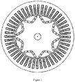
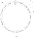
- majority of driving motors for vehicles as represented by Toyota Prius adopt a plan with 48 slots for the stator and 8 poles for the rotor
- ISG motors represented by Hyundai IMA adopt a plan of concentrated winding with a slot-pole ratio of 3:2.
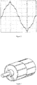
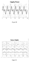
- Figure 1 shows a permanent magnet synchronous motor with 48 slots and 8 poles for the Toyota Prius, which exhibits rich harmonic content in its back EMF waveform since neither the stator nor the rotor is skewed, as is shown on Figure 2 , resulting not only in increased iron loss, in precision error in determination of the rotor angle during calibration, but also in apparent accompanied cogging torque and torque ripple.
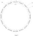
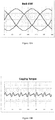
- a permanent magnet synchronous motor with rotor step skewing employed for the Nissan LEAF is shown on Figure 3 , which substantially improves back EMF waveform, reduces both cogging torque and torque ripple.
- the motor's peak capacity is wakened, and manufacturing of the rotor get more complex.
- the technical problem the present invention aims to solve is to provide a permanent magnet synchronous motor and a rotor thereof for reducing cogging torque and torque ripple in low torque area, which has a simple structure and low cost and is easy to manufacture.
- the present invention provides a permanent magnet synchronous motor comprising a rotor according to claim 1.
- a q-axis surface groove is arranged on an outer surface along the axis of the iron core in the middle in-between the pair of the adjacent S pole magnet plate and the N pole magnet plate.
- a stator of the fractional slot concentrated winding permanent magnet synchronous motor has 24 stator teeth and around the axis of the iron core are internally arranged 8 S pole magnet plates and 8 N pole magnet plates alternatively and evenly.
- an open width of the d-axis surface groove is 50% to 150% of a width of a tooth shoe of the stator tooth of the permanent magnet synchronous motor
- a depth of the d-axis surface groove is 20% to 80% of an air gap
- the inter-axis distance of the two d-axis surface grooves of each magnet plates is 90%, 100% or 110% of the tooth tip span of the stator tooth of the permanent magnet synchronous motor.
- the d-axis surface groove is in a minor arc shape.
- the permanent magnet synchronous motor of the present invention increases fundamental component percentage in a cycle of air gap flux density, reduces back EMF harmonic content in the flux density waveform, that is to say, the air gap flux density has a low sinusoidal distortion.
- the magnetic field of the motor without power supply is provided solely by the magnet plates with the torque generated by the rotor being related only to the flux density magnitude and the magnetic permeability, thus cogging torque is diminished if the flux density waveform is sinusoidal in a linear condition.
- the permanent magnet synchronous motor of the present invention reduces cogging torque resulting from air gap flux density waveform distortion due to stator slotting, thus reduces level of torque ripple of the motor under load, particularly for the torque ripple in a low torque area.
- the permanent magnet synchronous motor of the present invention has a simple rotor structure and low cost and is easy to manufacture.
- Cogging torque results from a tangential component of an uneven interacting force between a permanent magnet body of the permanent magnet synchronous motor and the stator teeth of a slotted stator.
- each magnet plate on the surface of the rotor iron core of each magnet plate are arranged two d-axis surface grooves 14, wherein the inter-axis distance of the two d-axis surface grooves 14 of each magnet plates is approximately equal to the tooth tip span w of the stator tooth of the permanent magnet synchronous motor.
- the permanent magnet synchronous motor of example one increases fundamental component percentage in a cycle of air gap flux density, reduces back EMF harmonic content in the flux density waveform, that is to say, the air gap flux density has a low sinusoidal distortion.
- the magnetic field of the motor without power supply is provided solely by the magnet plates with the torque generated by the rotor being related only to the flux density magnitude and the magnetic permeability, thus cogging torque is diminished if the flux density waveform is sinusoidal in a linear condition.
- the permanent magnet synchronous motor of example one reduces cogging torque resulting from air gap flux density waveform distortion due to stator slotting, thus reducing level of torque ripple of the motor under load.
- the permanent magnet synchronous motor of example one has a simple rotor structure and low cost, and is easy to manufacture.
- the open width of the d-axis surface groove 14 is 50% to 150% (for example, 50%, 100%, or 150%) of the width L of the tooth shoe 21 of the stator tooth 2 of the permanent magnet synchronous motor, the depth of the d-axis surface groove 14 is 20% to 80% (for example, 20%, 50%, or 80%) of the air gap F.
- the air gap flux density comprises a constant component, a fundamental component, and a harmonic component, with the fundamental component solely contributing to the performance of the motor.
- the d-axis surface groove 14 is in a minor arc shape.
- the d-axis surface grooves 14 in a minor arc shape will further mitigate drastic change of the air gap flux density due to stator slotting, thus reducing drastic change in air gap flux density magnitude.
- such axial surface grooves affect mechanical strength of the rotor in a minor manner, and thus the rotor is easier to manufacture.
- Example two is based on the permanent magnet synchronous motor of example one, the permanent magnet synchronous motor being a fractional slot motor, as is shown on Figure 5 , with a q-axis surface groove 12 being arranged on an outer surface along the axis of the iron core in the middle (that is, the locus of the q axis) in-between the pair of the adjacent S pole magnet plate and the N pole magnet plate.
- the torque T of the permanent magnet synchronous motor is constituted principally of two parts, a synchronous torque generated by the permanent magnet flux (caused by excitation magnetic field of the permanent magnet material and the d-axis current), and a reluctance torque induced by inequality between the d-axis inductance Ld and the q-axis inductance Lq due to asymmetry of a d-axis magnetic circuit with a q-axis magnetic circuit, with the reluctance torque being capable of increasing the torque/current density of the permanent magnet motor on one hand and substantially increasing torque ripple on the other hand.
- the reluctance torque induced by inequality between the d-axis inductance Ld and the q-axis inductance Lq due to asymmetry of a d-axis magnetic circuit with a q-axis magnetic circuit only constitutes a small percentage, it is generally possible to substantially reduce the torque ripple by means of altering the shape of the q-axis magnetic circuit, with a total torque unchanged.
- the permanent magnet synchronous motor of example two is a fractional slot motor with d-axis surface grooves and q-axis surface grooves arranged on the surface of the rotor iron core.
- the permanent magnet synchronous motor is a fractional slot concentrated winding permanent magnet synchronous motor, with a slot number per pole per phase greater than or equal to 1/4 and less than or equal to 1/2.
- the embodiment is based on the permanent magnet synchronous motor of example two, as is shown on Figure 6 , and shows that a permanent magnet synchronous motor according to the invention is arranged with an internal hole 13 further arranged at the middle (that is, the locus of the q axis) in-between the adjacent S pole magnet plate and the N pole magnet plate of the iron core 1 internally along the axis thereof.
- Opening a hole internally on the q axis of the iron core not only reduces torque ripple due to saliency effect of the motor, but is also tantamount to a narrowed q-axis magnetic bridge, thus increasing magnetic field saturation at the locus, decreasing pole-pole leakage, and is equivalent to increasing the flux of the permanent magnet, that is, increasing magnet steel efficiency of the motor; moreover, opening a hole on the q axis of the iron core increases magnetoresistance of the q-axis magnetic circuit, and strengthens the anti-demagnetization of the magnetic steel, since a d-axis flux weakening reversed field entering the magnet steel is weakened under a same stator current.
- opening a hole on the q axis of the iron core, and with two d-axis surface grooves 14 arranged symmetric to the d axis on the surface of the rotor core of each magnet plate, reduces torque ripple due to saliency effect of the motor; it further curtails pole-pole leakage and increases magnet steel efficiency; it strengthens the anti-demagnetization of the magnetic steel, since a d-axis flux weakening reversed field entering the magnet steel is weakened under a same stator current; it reduces cogging torque and torque ripple in the whole area under an operating load, and achieves effect of step skewing.
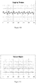
- FIG. 8A The back EMF of a permanent magnet synchronous motor with an untreated rotor not forming part of the invention is shown on Figure 8A
- the cogging torque of the permanent magnet synchronous motor with an untreated rotor is shown on Figure 8B
- the torque ripple of the permanent magnet synchronous motor with an untreated rotor is shown on Figure 8C .
Landscapes
- Engineering & Computer Science (AREA)
- Power Engineering (AREA)
- Permanent Magnet Type Synchronous Machine (AREA)
- Permanent Field Magnets Of Synchronous Machinery (AREA)
- Iron Core Of Rotating Electric Machines (AREA)
Claims (5)
- Permanentmagnet-Synchronmotor, umfassend einen Rotor, wobei der Rotor einen Eisenkern (1) in zylindrischer Form mit p S-Pol-Permanentmagnetplatten und p N-Pol-Permanentmagnetplatten (11) umfasst, die in dem Eisenkern um eine Achse davon angeordnet sind, wobei p eine positive ganze Zahl ist, und wobei die p S-Pol-Permanentmagnetplatten (11) und die p N-Pol-Permanentmagnetplatten (11) mit wechselnder Polarität in der Umfangsrichtung angeordnet sind; wobei auf einer Oberfläche eines Rotoreisenkerns entsprechend jeder Permanentmagnetplatte (11) zwei axiale d-Achsen-Oberflächennuten (14) angeordnet sind; wobei die zwei axialen d-Achsen-Oberflächennuten, entsprechend jeder Permanentmagnetplatte (11), auf zwei Seiten einer axialen Mittellinie der Permanentmagnetplatte liegen; wobei ein Umfangsabstand der zwei d-Achsen-Oberflächennuten jeder Permanentmagnetplatte (11) 90 % bis 110 % einer Zahnspitzenspannweite (W) eines Stator-Zahns (2) des Permanentmagnet-Synchronmotors beträgt, gekennzeichnet dadurch, dass
ein inneres Loch (13) innen entlang der Achse des Eisenkerns zwischen jedem Paar der benachbarten S-Pol-Magnetplatte und der N-Pol-Magnetplatte angeordnet ist,
wobei der Permanentmagnet-Synchronmotor ein Permanentmagnet-Synchronmotor mit bruchlochkonzentrierter Wicklung ist, wobei eine Lochanzahl pro Pol pro Phase größer oder gleich 1/4 ist und kleiner oder gleich 1/2 ist. - Permanentmagnet-Synchronmotor nach Anspruch 1, wobei in dem Rotor an einer äußeren Oberfläche entlang der Achse des Eisenkerns (1) in der Mitte zwischen dem Paar der benachbarten S-Pol-Permanentmagnetplatte und der N-Pol-Permanentmagnetplatte eine axiale q-Achsen-Oberflächennut (12) angeordnet ist.
- Permanentmagnet-Synchronmotor nach Anspruch 1, wobei der Motor 24 Stator-Zähne aufweist und wobei um die Achse des Eisenkerns (1) intern 8 S-Pol- und 8 N-Pol-Permanentmagnetplatten (11) abwechselnd und gleichmäßig angeordnet sind.
- Permanentmagnet-Synchronmotor nach Anspruch 1, wobei eine offene Breite der d-Achsen-Oberflächennut 50 % bis 150 % einer Breite eines Zahn-Schuhs (21) des Stator-Zahns (2) des Permanentmagnet-Synchronmotors beträgt, eine Tiefe der d-Achsen-Oberflächennut 20 % bis 80 % eines Luftspalts beträgt, und der Abstand zwischen den Achsen der zwei axialen d-Achsen-Oberflächennuten (14) von jeder Permanentmagnetplatte (11) 90 %, 100 % oder 110 % der Zahnspitzenspannweite (W) des Stator-Zahns des Permanentmagnet-Synchronmotors beträgt.
- Permanentmagnet-Synchronmotor nach Anspruch 1, wobei die axiale d-Achsen-Oberflächennut (14) eine geringfügige Bogenform hat.
Applications Claiming Priority (2)
| Application Number | Priority Date | Filing Date | Title |
|---|---|---|---|
| CN201410168537.9A CN103956872B (zh) | 2014-04-25 | 2014-04-25 | 永磁同步电机及其转子 |
| PCT/CN2014/095792 WO2015161668A1 (zh) | 2014-04-25 | 2014-12-31 | 永磁同步电机及其转子 |
Publications (3)
| Publication Number | Publication Date |
|---|---|
| EP3136559A1 EP3136559A1 (de) | 2017-03-01 |
| EP3136559A4 EP3136559A4 (de) | 2018-01-24 |
| EP3136559B1 true EP3136559B1 (de) | 2021-10-06 |
Family
ID=51334116
Family Applications (1)
| Application Number | Title | Priority Date | Filing Date |
|---|---|---|---|
| EP14889998.2A Active EP3136559B1 (de) | 2014-04-25 | 2014-12-31 | Permanentmagnetsynchronmotor und rotor dafür |
Country Status (6)
| Country | Link |
|---|---|
| US (1) | US20170047799A1 (de) |
| EP (1) | EP3136559B1 (de) |
| JP (1) | JP2017514453A (de) |
| KR (1) | KR20160149259A (de) |
| CN (1) | CN103956872B (de) |
| WO (1) | WO2015161668A1 (de) |
Families Citing this family (28)
| Publication number | Priority date | Publication date | Assignee | Title |
|---|---|---|---|---|
| CN103956872B (zh) * | 2014-04-25 | 2018-07-20 | 联合汽车电子有限公司 | 永磁同步电机及其转子 |
| CN103956874A (zh) * | 2014-04-25 | 2014-07-30 | 联合汽车电子有限公司 | 永磁同步电机及其转子 |
| CN105048746A (zh) * | 2015-08-11 | 2015-11-11 | 东菱技术有限公司 | 一种智能电网断路器用同步电机 |
| US10749391B2 (en) * | 2017-03-06 | 2020-08-18 | Ford Global Technologies, Llc | Electric machine rotor |
| CN106972667A (zh) * | 2017-05-24 | 2017-07-21 | 乐视汽车(北京)有限公司 | 一种电机的转子及其制造方法 |
| CN107086744B (zh) * | 2017-06-05 | 2023-06-06 | 河北双灿机械科技有限公司 | 转子理想正弦波气隙磁场永磁同步电机 |
| DE102017213653A1 (de) * | 2017-08-07 | 2019-02-07 | Magna powertrain gmbh & co kg | Antriebsvorrichtung |
| CN107846089A (zh) * | 2017-12-12 | 2018-03-27 | 盛瑞传动股份有限公司 | 一种变速箱用电机 |
| CN108110927A (zh) * | 2017-12-29 | 2018-06-01 | 上海崇林汽车电子有限公司 | 一种电动汽车永磁电机转子冲片 |
| CN208589826U (zh) * | 2018-06-11 | 2019-03-08 | 宝龙电子集团有限公司 | 一种驱动马达 |
| CN109167501B (zh) * | 2018-09-21 | 2023-10-31 | 沈阳工业大学 | 一种混合转子外转子同步电机 |
| CN109245468B (zh) * | 2018-09-21 | 2023-11-28 | 沈阳工业大学 | 一种采用永磁辅助笼障转子的双转子同步电机 |
| CN109660099B (zh) * | 2018-12-10 | 2024-07-12 | 陕西法士特齿轮有限责任公司 | 一种混合励磁同步电机 |
| CN109412301A (zh) * | 2018-12-25 | 2019-03-01 | 南京埃斯顿自动化股份有限公司 | 一种低惯量内置Flat型永磁伺服电机 |
| CN114598076A (zh) * | 2019-09-26 | 2022-06-07 | 广东威灵电机制造有限公司 | 电机和家用电器 |
| CN110661352A (zh) * | 2019-09-27 | 2020-01-07 | 西安佳中电子技术有限公司 | 转子及永磁发电机 |
| CN110601486A (zh) * | 2019-11-01 | 2019-12-20 | 哈尔滨理工大学 | 一种高效扩速的内置式永磁同步电机结构 |
| CN112671192B (zh) * | 2020-12-31 | 2022-03-25 | 山东理工大学 | 一种汽车用磁齿轮永磁电机 |
| CN113162356A (zh) * | 2021-03-04 | 2021-07-23 | 北京航空航天大学 | 一种高空无人机用高功率密度驱动器 |
| US11632021B2 (en) * | 2021-04-05 | 2023-04-18 | Raytheon Company | Dynamo-electric machine |
| CN113178967B (zh) * | 2021-04-30 | 2023-04-07 | 哈尔滨工业大学 | 大功率高速永磁同步电机转子 |
| KR20230022603A (ko) * | 2021-08-09 | 2023-02-16 | 엘지이노텍 주식회사 | 모터 |
| CN114142648B (zh) * | 2021-12-07 | 2023-09-15 | 江苏集萃智能制造技术研究所有限公司 | 一种无框力矩电机及其测试方法 |
| CN114665630B (zh) * | 2022-03-16 | 2023-02-03 | 华为电动技术有限公司 | 一种电机转子、电机、动力总成以及电动车 |
| CN114915070B (zh) * | 2022-05-09 | 2024-01-09 | 山东大学 | 基于双v形永磁体的转子及高速轴向磁通永磁电机 |
| CN115347698B (zh) * | 2022-07-04 | 2024-06-28 | 北京航空航天大学 | 一种Halbach磁极阵列结构、内转子及永磁同步电机 |
| CN115149765B (zh) * | 2022-07-05 | 2024-06-28 | 北京航空航天大学 | 一种六相容错永磁同步电机 |
| CN115776185B (zh) * | 2022-10-17 | 2025-08-15 | 珠海凌达压缩机有限公司 | 转子铁芯、电机及压缩机 |
Citations (1)
| Publication number | Priority date | Publication date | Assignee | Title |
|---|---|---|---|---|
| JP2011239609A (ja) * | 2010-05-12 | 2011-11-24 | Toshiba Corp | 永久磁石式回転電機 |
Family Cites Families (22)
| Publication number | Priority date | Publication date | Assignee | Title |
|---|---|---|---|---|
| JP2000295805A (ja) * | 1999-04-07 | 2000-10-20 | Toyota Motor Corp | 永久磁石回転電機 |
| TW538578B (en) * | 2000-09-13 | 2003-06-21 | Sanyo Electric Co | Synchronous motor with built-in type permanent magnet |
| US6727623B2 (en) * | 2002-08-28 | 2004-04-27 | Emerson Electric Co. | Reduced impedance interior permanent magnet machine |
| US6946766B2 (en) * | 2002-08-28 | 2005-09-20 | Emerson Electric Co. | Permanent magnet machine |
| KR101092321B1 (ko) * | 2005-12-21 | 2011-12-09 | 주식회사 동서전자 | Lspm 동기모터의 로터 |
| JP4135018B2 (ja) * | 2006-04-24 | 2008-08-20 | 株式会社富士通ゼネラル | 磁石埋め込み型回転子、この回転子を用いた電動機及びこの電動機を用いた圧縮機 |
| US7932658B2 (en) * | 2007-03-15 | 2011-04-26 | A.O. Smith Corporation | Interior permanent magnet motor including rotor with flux barriers |
| JP4900069B2 (ja) * | 2007-06-13 | 2012-03-21 | トヨタ自動車株式会社 | 回転電機 |
| CN101981783B (zh) * | 2008-03-27 | 2014-01-01 | 松下电器产业株式会社 | 永久磁铁埋入式转子以及使用它的电动机及电气设备 |
| WO2010013444A1 (ja) * | 2008-07-28 | 2010-02-04 | 株式会社日立製作所 | 永久磁石同期電動機 |
| JP5260563B2 (ja) * | 2010-01-07 | 2013-08-14 | 株式会社日立製作所 | 永久磁石式発電機またはモータ |
| WO2013026088A1 (en) * | 2011-08-19 | 2013-02-28 | Newsouth Innovations Pty Limited | Interior permanent magnet machine |
| CN102355071A (zh) * | 2011-09-28 | 2012-02-15 | 苏州和鑫电气股份有限公司 | 内置式永磁电机转子和包含该转子的电机 |
| CN202260721U (zh) * | 2011-10-31 | 2012-05-30 | 上海中科深江电动车辆有限公司 | 永磁电机内置式转子结构 |
| JP2013099193A (ja) * | 2011-11-04 | 2013-05-20 | Suzuki Motor Corp | 電動回転機 |
| JP2013162556A (ja) * | 2012-02-01 | 2013-08-19 | Suzuki Motor Corp | 電動回転機 |
| JP5966409B2 (ja) * | 2012-02-15 | 2016-08-10 | 日産自動車株式会社 | 回転電動機 |
| US20130320798A1 (en) * | 2012-05-30 | 2013-12-05 | Steering Solutions Ip Holding Corporation | System and method for reducing cogging torque in an interior permanent magnet motor |
| WO2014027631A1 (ja) * | 2012-08-16 | 2014-02-20 | 株式会社ミツバ | ブラシレスモータ及びブラシレスモータ用ロータ |
| JP2014050211A (ja) * | 2012-08-31 | 2014-03-17 | Hitachi Automotive Systems Ltd | 永久磁石回転電機 |
| CN203896152U (zh) * | 2014-04-25 | 2014-10-22 | 联合汽车电子有限公司 | 永磁同步电机及其转子 |
| CN103956872B (zh) * | 2014-04-25 | 2018-07-20 | 联合汽车电子有限公司 | 永磁同步电机及其转子 |
-
2014
- 2014-04-25 CN CN201410168537.9A patent/CN103956872B/zh active Active
- 2014-12-31 US US15/306,568 patent/US20170047799A1/en not_active Abandoned
- 2014-12-31 KR KR1020167033132A patent/KR20160149259A/ko not_active Withdrawn
- 2014-12-31 EP EP14889998.2A patent/EP3136559B1/de active Active
- 2014-12-31 JP JP2017507051A patent/JP2017514453A/ja active Pending
- 2014-12-31 WO PCT/CN2014/095792 patent/WO2015161668A1/zh not_active Ceased
Patent Citations (1)
| Publication number | Priority date | Publication date | Assignee | Title |
|---|---|---|---|---|
| JP2011239609A (ja) * | 2010-05-12 | 2011-11-24 | Toshiba Corp | 永久磁石式回転電機 |
Also Published As
| Publication number | Publication date |
|---|---|
| JP2017514453A (ja) | 2017-06-01 |
| US20170047799A1 (en) | 2017-02-16 |
| WO2015161668A1 (zh) | 2015-10-29 |
| EP3136559A1 (de) | 2017-03-01 |
| KR20160149259A (ko) | 2016-12-27 |
| CN103956872B (zh) | 2018-07-20 |
| EP3136559A4 (de) | 2018-01-24 |
| CN103956872A (zh) | 2014-07-30 |
Similar Documents
| Publication | Publication Date | Title |
|---|---|---|
| EP3136559B1 (de) | Permanentmagnetsynchronmotor und rotor dafür | |
| JP4680442B2 (ja) | モータの回転子 | |
| KR101736369B1 (ko) | 디텐트 토크가 낮은 3상 전기 모터 | |
| US9252634B2 (en) | Synchronous motor | |
| CN104221261B (zh) | 永磁铁马达 | |
| EP3329577B1 (de) | Synchroner permanentmagnetmotor | |
| CN104253499B (zh) | 电动汽车用直轴磁场增强型宽调速永磁无刷电机 | |
| EP2056431A1 (de) | Rotor einer elektrischen dreheinrichtung des permanentmagneten | |
| JP5565170B2 (ja) | 永久磁石式回転機 | |
| CN101785168A (zh) | 一种特别地用于汽车驱动的电流激发同步电动机 | |
| Dajaku et al. | New methods for reducing the cogging torque and torque ripples of PMSM | |
| KR20140094516A (ko) | 회전 전기 기계의 회전자, 및 회전자를 포함하는 회전 전기 기계 | |
| JPWO2014038062A1 (ja) | 永久磁石埋込型電動機 | |
| JP2017055560A (ja) | 永久磁石式回転電機 | |
| EP1713163A1 (de) | Elektrische ipm-drehmaschine | |
| CN203896152U (zh) | 永磁同步电机及其转子 | |
| JP5041415B2 (ja) | アキシャルギャップ型モータ | |
| CN108141076B (zh) | 磁铁式转子、具备磁铁式转子的旋转电机以及具备旋转电机的电动汽车 | |
| JP5805046B2 (ja) | 車両用電動機および車両用発電機 | |
| JP7507840B2 (ja) | 回転電機、回転電動機駆動システム、並びに電動車両 | |
| CN103956873A (zh) | 永磁同步电机及其转子 | |
| CN103956874A (zh) | 永磁同步电机及其转子 | |
| JP2008206351A (ja) | Pmシンクロナスモータ | |
| JP2011083114A (ja) | 電動機 | |
| Zhu | Design, analysis and implementation of a spoke-type motor with high-performance ferrite magnets for electric vehicle applications |
Legal Events
| Date | Code | Title | Description |
|---|---|---|---|
| STAA | Information on the status of an ep patent application or granted ep patent |
Free format text: STATUS: THE INTERNATIONAL PUBLICATION HAS BEEN MADE |
|
| PUAI | Public reference made under article 153(3) epc to a published international application that has entered the european phase |
Free format text: ORIGINAL CODE: 0009012 |
|
| STAA | Information on the status of an ep patent application or granted ep patent |
Free format text: STATUS: REQUEST FOR EXAMINATION WAS MADE |
|
| 17P | Request for examination filed |
Effective date: 20161123 |
|
| AK | Designated contracting states |
Kind code of ref document: A1 Designated state(s): AL AT BE BG CH CY CZ DE DK EE ES FI FR GB GR HR HU IE IS IT LI LT LU LV MC MK MT NL NO PL PT RO RS SE SI SK SM TR |
|
| AX | Request for extension of the european patent |
Extension state: BA ME |
|
| DAX | Request for extension of the european patent (deleted) | ||
| A4 | Supplementary search report drawn up and despatched |
Effective date: 20171221 |
|
| RIC1 | Information provided on ipc code assigned before grant |
Ipc: H02K 29/03 20060101AFI20171215BHEP Ipc: H02K 1/27 20060101ALN20171215BHEP Ipc: H02K 21/16 20060101ALN20171215BHEP |
|
| STAA | Information on the status of an ep patent application or granted ep patent |
Free format text: STATUS: EXAMINATION IS IN PROGRESS |
|
| 17Q | First examination report despatched |
Effective date: 20190409 |
|
| RIC1 | Information provided on ipc code assigned before grant |
Ipc: H02K 29/03 20060101AFI20210312BHEP Ipc: H02K 21/16 20060101ALN20210312BHEP Ipc: H02K 1/27 20060101ALN20210312BHEP |
|
| REG | Reference to a national code |
Ref country code: DE Ref legal event code: R079 Ref document number: 602014080573 Country of ref document: DE Free format text: PREVIOUS MAIN CLASS: H02K0021020000 Ipc: H02K0029030000 |
|
| RIC1 | Information provided on ipc code assigned before grant |
Ipc: H02K 29/03 20060101AFI20210319BHEP Ipc: H02K 21/16 20060101ALN20210319BHEP Ipc: H02K 1/27 20060101ALN20210319BHEP |
|
| GRAJ | Information related to disapproval of communication of intention to grant by the applicant or resumption of examination proceedings by the epo deleted |
Free format text: ORIGINAL CODE: EPIDOSDIGR1 |
|
| STAA | Information on the status of an ep patent application or granted ep patent |
Free format text: STATUS: GRANT OF PATENT IS INTENDED |
|
| RIC1 | Information provided on ipc code assigned before grant |
Ipc: H02K 29/03 20060101AFI20210401BHEP Ipc: H02K 21/16 20060101ALN20210401BHEP Ipc: H02K 1/27 20060101ALN20210401BHEP |
|
| GRAP | Despatch of communication of intention to grant a patent |
Free format text: ORIGINAL CODE: EPIDOSNIGR1 |
|
| RIC1 | Information provided on ipc code assigned before grant |
Ipc: H02K 29/03 20060101AFI20210422BHEP Ipc: H02K 21/16 20060101ALN20210422BHEP Ipc: H02K 1/27 20060101ALN20210422BHEP |
|
| RIC1 | Information provided on ipc code assigned before grant |
Ipc: H02K 29/03 20060101AFI20210426BHEP Ipc: H02K 21/16 20060101ALN20210426BHEP Ipc: H02K 1/27 20060101ALN20210426BHEP |
|
| INTG | Intention to grant announced |
Effective date: 20210514 |
|
| GRAS | Grant fee paid |
Free format text: ORIGINAL CODE: EPIDOSNIGR3 |
|
| GRAA | (expected) grant |
Free format text: ORIGINAL CODE: 0009210 |
|
| STAA | Information on the status of an ep patent application or granted ep patent |
Free format text: STATUS: THE PATENT HAS BEEN GRANTED |
|
| AK | Designated contracting states |
Kind code of ref document: B1 Designated state(s): AL AT BE BG CH CY CZ DE DK EE ES FI FR GB GR HR HU IE IS IT LI LT LU LV MC MK MT NL NO PL PT RO RS SE SI SK SM TR |
|
| REG | Reference to a national code |
Ref country code: GB Ref legal event code: FG4D |
|
| REG | Reference to a national code |
Ref country code: CH Ref legal event code: EP Ref country code: AT Ref legal event code: REF Ref document number: 1437046 Country of ref document: AT Kind code of ref document: T Effective date: 20211015 |
|
| REG | Reference to a national code |
Ref country code: IE Ref legal event code: FG4D |
|
| REG | Reference to a national code |
Ref country code: DE Ref legal event code: R096 Ref document number: 602014080573 Country of ref document: DE |
|
| REG | Reference to a national code |
Ref country code: LT Ref legal event code: MG9D |
|
| REG | Reference to a national code |
Ref country code: NL Ref legal event code: MP Effective date: 20211006 |
|
| REG | Reference to a national code |
Ref country code: AT Ref legal event code: MK05 Ref document number: 1437046 Country of ref document: AT Kind code of ref document: T Effective date: 20211006 |
|
| PG25 | Lapsed in a contracting state [announced via postgrant information from national office to epo] |
Ref country code: RS Free format text: LAPSE BECAUSE OF FAILURE TO SUBMIT A TRANSLATION OF THE DESCRIPTION OR TO PAY THE FEE WITHIN THE PRESCRIBED TIME-LIMIT Effective date: 20211006 Ref country code: LT Free format text: LAPSE BECAUSE OF FAILURE TO SUBMIT A TRANSLATION OF THE DESCRIPTION OR TO PAY THE FEE WITHIN THE PRESCRIBED TIME-LIMIT Effective date: 20211006 Ref country code: FI Free format text: LAPSE BECAUSE OF FAILURE TO SUBMIT A TRANSLATION OF THE DESCRIPTION OR TO PAY THE FEE WITHIN THE PRESCRIBED TIME-LIMIT Effective date: 20211006 Ref country code: BG Free format text: LAPSE BECAUSE OF FAILURE TO SUBMIT A TRANSLATION OF THE DESCRIPTION OR TO PAY THE FEE WITHIN THE PRESCRIBED TIME-LIMIT Effective date: 20220106 Ref country code: AT Free format text: LAPSE BECAUSE OF FAILURE TO SUBMIT A TRANSLATION OF THE DESCRIPTION OR TO PAY THE FEE WITHIN THE PRESCRIBED TIME-LIMIT Effective date: 20211006 |
|
| PG25 | Lapsed in a contracting state [announced via postgrant information from national office to epo] |
Ref country code: IS Free format text: LAPSE BECAUSE OF FAILURE TO SUBMIT A TRANSLATION OF THE DESCRIPTION OR TO PAY THE FEE WITHIN THE PRESCRIBED TIME-LIMIT Effective date: 20220206 Ref country code: SE Free format text: LAPSE BECAUSE OF FAILURE TO SUBMIT A TRANSLATION OF THE DESCRIPTION OR TO PAY THE FEE WITHIN THE PRESCRIBED TIME-LIMIT Effective date: 20211006 Ref country code: PT Free format text: LAPSE BECAUSE OF FAILURE TO SUBMIT A TRANSLATION OF THE DESCRIPTION OR TO PAY THE FEE WITHIN THE PRESCRIBED TIME-LIMIT Effective date: 20220207 Ref country code: PL Free format text: LAPSE BECAUSE OF FAILURE TO SUBMIT A TRANSLATION OF THE DESCRIPTION OR TO PAY THE FEE WITHIN THE PRESCRIBED TIME-LIMIT Effective date: 20211006 Ref country code: NO Free format text: LAPSE BECAUSE OF FAILURE TO SUBMIT A TRANSLATION OF THE DESCRIPTION OR TO PAY THE FEE WITHIN THE PRESCRIBED TIME-LIMIT Effective date: 20220106 Ref country code: NL Free format text: LAPSE BECAUSE OF FAILURE TO SUBMIT A TRANSLATION OF THE DESCRIPTION OR TO PAY THE FEE WITHIN THE PRESCRIBED TIME-LIMIT Effective date: 20211006 Ref country code: LV Free format text: LAPSE BECAUSE OF FAILURE TO SUBMIT A TRANSLATION OF THE DESCRIPTION OR TO PAY THE FEE WITHIN THE PRESCRIBED TIME-LIMIT Effective date: 20211006 Ref country code: HR Free format text: LAPSE BECAUSE OF FAILURE TO SUBMIT A TRANSLATION OF THE DESCRIPTION OR TO PAY THE FEE WITHIN THE PRESCRIBED TIME-LIMIT Effective date: 20211006 Ref country code: GR Free format text: LAPSE BECAUSE OF FAILURE TO SUBMIT A TRANSLATION OF THE DESCRIPTION OR TO PAY THE FEE WITHIN THE PRESCRIBED TIME-LIMIT Effective date: 20220107 Ref country code: ES Free format text: LAPSE BECAUSE OF FAILURE TO SUBMIT A TRANSLATION OF THE DESCRIPTION OR TO PAY THE FEE WITHIN THE PRESCRIBED TIME-LIMIT Effective date: 20211006 |
|
| REG | Reference to a national code |
Ref country code: DE Ref legal event code: R097 Ref document number: 602014080573 Country of ref document: DE |
|
| PG25 | Lapsed in a contracting state [announced via postgrant information from national office to epo] |
Ref country code: SM Free format text: LAPSE BECAUSE OF FAILURE TO SUBMIT A TRANSLATION OF THE DESCRIPTION OR TO PAY THE FEE WITHIN THE PRESCRIBED TIME-LIMIT Effective date: 20211006 Ref country code: SK Free format text: LAPSE BECAUSE OF FAILURE TO SUBMIT A TRANSLATION OF THE DESCRIPTION OR TO PAY THE FEE WITHIN THE PRESCRIBED TIME-LIMIT Effective date: 20211006 Ref country code: RO Free format text: LAPSE BECAUSE OF FAILURE TO SUBMIT A TRANSLATION OF THE DESCRIPTION OR TO PAY THE FEE WITHIN THE PRESCRIBED TIME-LIMIT Effective date: 20211006 Ref country code: MC Free format text: LAPSE BECAUSE OF FAILURE TO SUBMIT A TRANSLATION OF THE DESCRIPTION OR TO PAY THE FEE WITHIN THE PRESCRIBED TIME-LIMIT Effective date: 20211006 Ref country code: EE Free format text: LAPSE BECAUSE OF FAILURE TO SUBMIT A TRANSLATION OF THE DESCRIPTION OR TO PAY THE FEE WITHIN THE PRESCRIBED TIME-LIMIT Effective date: 20211006 Ref country code: DK Free format text: LAPSE BECAUSE OF FAILURE TO SUBMIT A TRANSLATION OF THE DESCRIPTION OR TO PAY THE FEE WITHIN THE PRESCRIBED TIME-LIMIT Effective date: 20211006 Ref country code: CZ Free format text: LAPSE BECAUSE OF FAILURE TO SUBMIT A TRANSLATION OF THE DESCRIPTION OR TO PAY THE FEE WITHIN THE PRESCRIBED TIME-LIMIT Effective date: 20211006 |
|
| REG | Reference to a national code |
Ref country code: CH Ref legal event code: PL |
|
| PLBE | No opposition filed within time limit |
Free format text: ORIGINAL CODE: 0009261 |
|
| STAA | Information on the status of an ep patent application or granted ep patent |
Free format text: STATUS: NO OPPOSITION FILED WITHIN TIME LIMIT |
|
| 26N | No opposition filed |
Effective date: 20220707 |
|
| REG | Reference to a national code |
Ref country code: BE Ref legal event code: MM Effective date: 20211231 |
|
| PG25 | Lapsed in a contracting state [announced via postgrant information from national office to epo] |
Ref country code: LU Free format text: LAPSE BECAUSE OF NON-PAYMENT OF DUE FEES Effective date: 20211231 Ref country code: IE Free format text: LAPSE BECAUSE OF NON-PAYMENT OF DUE FEES Effective date: 20211231 Ref country code: AL Free format text: LAPSE BECAUSE OF FAILURE TO SUBMIT A TRANSLATION OF THE DESCRIPTION OR TO PAY THE FEE WITHIN THE PRESCRIBED TIME-LIMIT Effective date: 20211006 |
|
| PG25 | Lapsed in a contracting state [announced via postgrant information from national office to epo] |
Ref country code: SI Free format text: LAPSE BECAUSE OF FAILURE TO SUBMIT A TRANSLATION OF THE DESCRIPTION OR TO PAY THE FEE WITHIN THE PRESCRIBED TIME-LIMIT Effective date: 20211006 Ref country code: FR Free format text: LAPSE BECAUSE OF NON-PAYMENT OF DUE FEES Effective date: 20211231 Ref country code: BE Free format text: LAPSE BECAUSE OF NON-PAYMENT OF DUE FEES Effective date: 20211231 |
|
| PG25 | Lapsed in a contracting state [announced via postgrant information from national office to epo] |
Ref country code: LI Free format text: LAPSE BECAUSE OF NON-PAYMENT OF DUE FEES Effective date: 20211231 Ref country code: CH Free format text: LAPSE BECAUSE OF NON-PAYMENT OF DUE FEES Effective date: 20211231 |
|
| PG25 | Lapsed in a contracting state [announced via postgrant information from national office to epo] |
Ref country code: IT Free format text: LAPSE BECAUSE OF FAILURE TO SUBMIT A TRANSLATION OF THE DESCRIPTION OR TO PAY THE FEE WITHIN THE PRESCRIBED TIME-LIMIT Effective date: 20211006 Ref country code: HU Free format text: LAPSE BECAUSE OF FAILURE TO SUBMIT A TRANSLATION OF THE DESCRIPTION OR TO PAY THE FEE WITHIN THE PRESCRIBED TIME-LIMIT; INVALID AB INITIO Effective date: 20141231 |
|
| PG25 | Lapsed in a contracting state [announced via postgrant information from national office to epo] |
Ref country code: CY Free format text: LAPSE BECAUSE OF FAILURE TO SUBMIT A TRANSLATION OF THE DESCRIPTION OR TO PAY THE FEE WITHIN THE PRESCRIBED TIME-LIMIT Effective date: 20211006 |
|
| PG25 | Lapsed in a contracting state [announced via postgrant information from national office to epo] |
Ref country code: MK Free format text: LAPSE BECAUSE OF FAILURE TO SUBMIT A TRANSLATION OF THE DESCRIPTION OR TO PAY THE FEE WITHIN THE PRESCRIBED TIME-LIMIT Effective date: 20211006 |
|
| PG25 | Lapsed in a contracting state [announced via postgrant information from national office to epo] |
Ref country code: MT Free format text: LAPSE BECAUSE OF FAILURE TO SUBMIT A TRANSLATION OF THE DESCRIPTION OR TO PAY THE FEE WITHIN THE PRESCRIBED TIME-LIMIT Effective date: 20211006 |
|
| PGFP | Annual fee paid to national office [announced via postgrant information from national office to epo] |
Ref country code: DE Payment date: 20241216 Year of fee payment: 11 |
|
| PGFP | Annual fee paid to national office [announced via postgrant information from national office to epo] |
Ref country code: GB Payment date: 20241217 Year of fee payment: 11 |
|
| PG25 | Lapsed in a contracting state [announced via postgrant information from national office to epo] |
Ref country code: TR Free format text: LAPSE BECAUSE OF FAILURE TO SUBMIT A TRANSLATION OF THE DESCRIPTION OR TO PAY THE FEE WITHIN THE PRESCRIBED TIME-LIMIT Effective date: 20211006 |