EP3779922B1 - Verfahren zur schätzung eines fahrwegs und fahrwegschätzsystem - Google Patents
Verfahren zur schätzung eines fahrwegs und fahrwegschätzsystem Download PDFInfo
- Publication number
- EP3779922B1 EP3779922B1 EP19803310.2A EP19803310A EP3779922B1 EP 3779922 B1 EP3779922 B1 EP 3779922B1 EP 19803310 A EP19803310 A EP 19803310A EP 3779922 B1 EP3779922 B1 EP 3779922B1
- Authority
- EP
- European Patent Office
- Prior art keywords
- target
- probability value
- track point
- moving object
- vehicle
- Prior art date
- Legal status (The legal status is an assumption and is not a legal conclusion. Google has not performed a legal analysis and makes no representation as to the accuracy of the status listed.)
- Active
Links
Images


Classifications
-
- G—PHYSICS
- G08—SIGNALLING
- G08G—TRAFFIC CONTROL SYSTEMS
- G08G1/00—Traffic control systems for road vehicles
- G08G1/16—Anti-collision systems
- G08G1/167—Driving aids for lane monitoring, lane changing, e.g. blind spot detection
-
- B—PERFORMING OPERATIONS; TRANSPORTING
- B60—VEHICLES IN GENERAL
- B60W—CONJOINT CONTROL OF VEHICLE SUB-UNITS OF DIFFERENT TYPE OR DIFFERENT FUNCTION; CONTROL SYSTEMS SPECIALLY ADAPTED FOR HYBRID VEHICLES; ROAD VEHICLE DRIVE CONTROL SYSTEMS FOR PURPOSES NOT RELATED TO THE CONTROL OF A PARTICULAR SUB-UNIT
- B60W60/00—Drive control systems specially adapted for autonomous road vehicles
- B60W60/001—Planning or execution of driving tasks
- B60W60/0011—Planning or execution of driving tasks involving control alternatives for a single driving scenario, e.g. planning several paths to avoid obstacles
-
- G—PHYSICS
- G01—MEASURING; TESTING
- G01C—MEASURING DISTANCES, LEVELS OR BEARINGS; SURVEYING; NAVIGATION; GYROSCOPIC INSTRUMENTS; PHOTOGRAMMETRY OR VIDEOGRAMMETRY
- G01C21/00—Navigation; Navigational instruments not provided for in groups G01C1/00 - G01C19/00
- G01C21/26—Navigation; Navigational instruments not provided for in groups G01C1/00 - G01C19/00 specially adapted for navigation in a road network
- G01C21/34—Route searching; Route guidance
- G01C21/3407—Route searching; Route guidance specially adapted for specific applications
- G01C21/343—Calculating itineraries
-
- B—PERFORMING OPERATIONS; TRANSPORTING
- B60—VEHICLES IN GENERAL
- B60W—CONJOINT CONTROL OF VEHICLE SUB-UNITS OF DIFFERENT TYPE OR DIFFERENT FUNCTION; CONTROL SYSTEMS SPECIALLY ADAPTED FOR HYBRID VEHICLES; ROAD VEHICLE DRIVE CONTROL SYSTEMS FOR PURPOSES NOT RELATED TO THE CONTROL OF A PARTICULAR SUB-UNIT
- B60W2554/00—Input parameters relating to objects
- B60W2554/40—Dynamic objects, e.g. animals, windblown objects
- B60W2554/404—Characteristics
- B60W2554/4049—Relationship among other objects, e.g. converging dynamic objects
Definitions
- This application relates to the field of autonomous vehicle driving, and in particular, to a method for predicting a road occupancy map of a target moving object and a system for predicting a road occupancy map of a target moving object.
- the prior art provides an automatic vehicle following system.
- the automatic vehicle following system tracks a vehicle ahead based on vehicle-mounted radar and a vehicle-mounted camera, to control a velocity of a vehicle, so that the vehicle keeps a specific safe distance from the vehicle ahead.
- US 2010/063735 A1 provides a method, an apparatus, and a program of predicting an obstacle course, capable of appropriately predicting a course of an obstacle even under a complicated traffic environment.
- Embodiments of the present invention provide a driving road estimation method and a driving road estimation system that can improve safe driving.
- a first aspect of the embodiments of the present invention provides a method for predicting a road occupancy map of a target moving object according to appended claim 1.
- the vehicle needs to obtain only the target status information of the target moving object at the current moment; and in a process of obtaining the target status information, the vehicle can estimate, based on the target status information, the road region in which the vehicle travels at the subsequent moment, without relying on a surrounding environment. Because the region in which the vehicle travels at the subsequent moment and the region in which the target moving object travels at the subsequent moment that are determined by the vehicle do not overlap, the vehicle can safely travel in the estimated road region. This effectively improves driving safety and reliability of the vehicle.
- step B specifically includes the following steps.
- Step B1 The vehicle sets that the target status information satisfies a target Gaussian distribution N a x 1 ⁇ a x 1 2 .
- An expectation of the target Gaussian distribution is the lateral acceleration a x1 , a variance of the target Gaussian distribution is ⁇ a x 1 2 , and the variance ⁇ a x 1 2 represents a discrete degree of the target Gaussian distribution N a x 1 ⁇ a x 1 2 ; and the target status information satisfying the target Gaussian distribution N a x 1 ⁇ a x 1 2 is discretized into 2( k +1) intervals, where k is a preset discretization coefficient.
- k in this embodiment may be inversely proportional to resolution f of a map stored in the vehicle, that is, k ⁇ 1/f, and the resolution f of the map is measured by using meters.
- Step B2 The vehicle performs sampling in a target interval to obtain a target discrete value.
- the target interval is any interval included in the 2( k +1) intervals formed by a bell-shaped region that is obtained after the target status information is discretized.
- Step B3 The vehicle obtains a target probability value corresponding to the target discrete value.
- the target probability value that is corresponding to the target discrete value and that is obtained by the vehicle is equal to an area of the target interval.
- Step B4 The vehicle sets the target probability value in the parameter sequence.
- the probability value obtained by the vehicle is corresponding to the target discrete value and the target discrete value.
- the vehicle may perform discretization processing on the lateral acceleration of the moving object in a probability discretization processing manner that is based on the Gaussian distribution, to obtain the parameter sequence including a plurality of discrete values, so as to effectively reduce calculation difficulty in estimating the parameter sequence by the vehicle, and increase a speed of calculating the target probability value.
- This effectively improves efficiency of estimating, by the vehicle, the road region in which the target moving object travels at the subsequent moment.
- a specific execution process of step B3 includes the following step.
- Step B31 The vehicle determines, according to a first formula, the target probability value P i corresponding to the target discrete value.
- the target status information further includes the longitudinal acceleration a y1 of the target moving object, and the target interval is an i th interval in the 2( k +1) intervals.
- step B3 the specific execution process of step B3 includes step B32: The vehicle determines, according to a second formula, the target probability value P i corresponding to the target discrete value.
- step B3 the specific execution process of step B3 includes step B33: The vehicle determines, according to a third formula, the target probability value P i corresponding to the target discrete value.
- step B34 The vehicle determines, according to a fourth formula, the target probability value P i corresponding to the target discrete value.
- the vehicle can accurately calculate the target probability value corresponding to the target discrete value, so that based on the accurate target probability value, the vehicle can effectively improve accuracy of estimating, by the vehicle, the road region in which the target moving object travels at the subsequent moment.
- step C specifically includes the following steps.
- Step C1 The vehicle determines, according to a fifth formula, coordinates ( x t 0 +n ⁇ t , y t 0 +n ⁇ t ) of a target track point included in the target movement track.
- the vehicle may determine, according to the fifth formula, the coordinates ( x t 0 +n ⁇ t , y t 0 +n ⁇ t ) of the target track point included in the target movement track, where the target track point is an n th track point in a plurality of track points included in the target movement track, t 0 is the current moment, ⁇ t is a predicted time step, and n is a positive integer greater than or equal to 0;
- the vehicle when the vehicle can accurately predict coordinates of any track point included in the target movement track, the vehicle can predict the target movement track, so as to effectively improve accuracy and efficiency of estimating, by the vehicle, the road region in which the target moving object travels at the subsequent moment.
- a specific execution process of step D includes the following steps.
- Step D1 The vehicle obtains a target probability value corresponding to each target track point included in the target movement track.
- the target probability value corresponding to the target track point is equal to the target probability value corresponding to the target discrete value.
- Step D2 The vehicle obtains a target track point that satisfies a regression fitting condition.
- the target track point that satisfies the regression fitting condition and that is obtained by the vehicle is a track point corresponding to a target probability value greater than or equal to a preset probability value.
- the vehicle determines the target probability value corresponding to the target track point included in the target movement track, if the target probability value is larger, it indicates that the target track point is more likely to belong to the road region of the target moving object at the subsequent moment; and if the target probability value is smaller, it indicates that the target track point is less likely to belong to the road region of the target moving object at the subsequent moment.
- the vehicle may perform, by using step D2, filtering on each track point included in the target movement track. In this way, a track point that is more likely to belong to the road region is reserved.
- Step D3 The vehicle performs regression fitting based on the target track point that satisfies the regression fitting condition, to obtain the road region in which the target moving object travels at the subsequent moment.
- the track point that is less likely to belong to the road region is effectively removed, to improve the reliability of the road region in which the vehicle travels at the subsequent moment and that is estimated by the vehicle. In this way, accuracy of the road region predicted by the vehicle is improved.
- step D1 specifically includes the following steps.
- Step D11 The vehicle performs, according to a sixth formula, attenuation processing on a target probability value P i corresponding to the target track point ( xt 0 + n ⁇ t , y t 0 + n ⁇ t ).
- a target probability value obtained after the vehicle performs the attenuation processing is a target probability value P (x t 0 + n ⁇ t ,y t 0 + n ⁇ t ).
- Step D12 The vehicle determines that the target probability value corresponding to the target track point is the target probability value p(x t 0 +n ⁇ t , y t 0 +n ⁇ t ) obtained after the attenuation processing.
- Accuracy of a track point included in the target movement track that is obtained by the vehicle by performing prediction on the target moving object is gradually reduced with time. If the accuracy of the track point estimated by the vehicle is higher, it indicates that a probability that the track point belongs to the road region in which the target moving object travels at the subsequent moment is higher. If the accuracy of the track point estimated by the vehicle is lower, it indicates that a probability that the track point belongs to the road region in which the target moving object travels at the subsequent moment is lower. Therefore, according to this implementation, the vehicle may perform attenuation processing on the target probability value as time goes by, so that accuracy of the track point can be improved by using a target probability value obtained after the attenuation processing.
- step D may further include the following steps.
- Step D13 The vehicle obtains a plurality of probability values corresponding to the target track point.
- the vehicle obtains the plurality of probability values corresponding to the target track point, where the first preset condition is that the target track point is located in different movement tracks.
- Step D14 The vehicle determines, as the target probability value corresponding to the target track point, a maximum value of probability values that are corresponding to the target track point in the different movement tracks.
- the vehicle predicts a movement track of the moving object at the subsequent moment, there is the target track point that satisfies the first preset condition, that is, the target track point is located in the different movement tracks when there is an overlap between spatial positions in the different movement tracks.
- the vehicle determines, as the target probability value, the maximum value of the probability values that are corresponding to the target track point in the different movement tracks, so that the accuracy of the track point can be improved by using the target probability value obtained after the attenuation processing.
- step D may further include the following steps.
- Step D15 The vehicle obtains a historical movement track that has been predicted for the target moving object at a historical moment.
- the historical moment is a previous moment of the current moment.
- Step D16 The vehicle obtains a first probability value and a second probability value that are corresponding to the target track point.
- the first probability value and the second probability value that are corresponding to the target track point are obtained, where the second preset condition is that the target track point is located in both the target movement track and the historical movement track, the first probability value is a probability value that is corresponding to the target track point and that is obtained by performing prediction on the target moving object at the current moment, and the second probability value is a probability value that is corresponding to the target track point and that is obtained by performing prediction on the target moving object at the historical moment.
- Step D17 The vehicle determines the larger of the first probability value and the second probability value as the target probability value corresponding to the target track point.
- the vehicle may obtain the target movement track by performing prediction on the target moving object at the current moment.
- the historical movement track and the target movement track intersect at an intersection point, and the intersection point is the target track point that satisfies the second preset condition.
- the vehicle determines the larger of the first probability value and the second probability value as the target probability value corresponding to the target track point.
- a second aspect of the embodiments of the present invention provides a driving road estimation system for predicting a road occupancy map of a target moving object according to appended claim 8.
- the processing unit includes:
- the second obtaining module when the target status information further includes the longitudinal acceleration a y1 of the target moving object, and the target interval is an i th interval in the 2( k +1) intervals, the second obtaining module specifically includes:
- the prediction unit is specifically configured to: determine, according to a fifth formula, coordinates ( x t 0 +n ⁇ t , y t 0 +n ⁇ t ) of a target track point included in the target movement track, where the target track point is an n th track point in a plurality of track points included in the target movement track, t 0 is the current moment, ⁇ t is a predicted time step, and n is a positive integer greater than or equal to 0;
- the determining unit includes:
- the first determining module includes:
- the first determining module includes:
- the first determining module includes:
- a fourth aspect of the embodiments of the present invention provides a computer-readable storage medium according to appended claim 15.
- the vehicle when obtaining the target status information of the surrounding target moving object, the vehicle may perform discretization processing on the target status information to obtain the parameter sequence, so that the vehicle can perform prediction based on the target status information and the target discrete value that is included in the parameter sequence, to obtain the target movement track.
- the vehicle can determine, based on the target movement track, the road region in which the target moving object travels at the subsequent moment, and then the vehicle can determine the region in which the vehicle travels at the subsequent moment, so that the region in which the vehicle travels at the subsequent moment does not overlap the region in which the target moving object travels at the subsequent moment.
- the vehicle needs to obtain only the target status information of the target moving object at the current moment, to estimate the road region in which the vehicle travels at the subsequent moment, without relying on a surrounding environment. In this way, the vehicle can safely travel in the estimated road region, thereby effectively improving driving safety and reliability of the vehicle.
- This application provides a driving road estimation method and a driving road estimation system.
- a specific hardware structure of a driving road estimation system to which the driving road estimation method is applied is first described with reference to FIG. 1 by using an example.
- the driving road estimation system in this application not only can be applied to driving of a vehicle, but also can be applied to driving of an airplane or a ship, so that the airplane or the ship can also travel on a traveling path.
- an example in which the driving road estimation system is applied to driving of a vehicle is used for description.
- the driving road estimation system in this embodiment is applied to a vehicle 100 is used for description.
- the driving road estimation system may alternatively run on a separate computing device.
- the computing device on which the driving road estimation system runs may be installed on the vehicle, so that the vehicle can perform the driving road estimation method in this application.
- the driving road estimation system in this embodiment may include a sensor layer 11, a data processing layer 12, and a vehicle control layer 13.
- the sensor layer 11 includes a camera 111, radar 112, a global positioning system (global positioning system, GPS) receiver 113, and the like.
- the camera 111 is responsible for acquiring a road scenario image.
- a specific device type of the camera 111 is not limited in this embodiment, provided that the camera 111 can acquire a scenario image of a road on which the vehicle exists.
- the camera 111 may be a monocular camera.
- the camera 111 may be a binocular camera.
- the radar 112 is responsible for data acquisition of a dynamic obstacle and data acquisition of a static obstacle to generate obstacle status data.
- the obstacle status data may be a position, a movement velocity, a movement direction, or the like of an obstacle.
- the radar 112 in this embodiment may be laser radar, millimeter-wave radar, or the like.
- the GPS receiver 113 is configured to receive a GPS signal and provide an initialized reference position for vehicle positioning.
- the GPS receiver 113 is an instrument for receiving a GPS satellite signal and determining a ground space position, where a navigation and positioning signal sent by a GPS satellite is an information resource that can be shared by a large quantity of users.
- Vast users on land and sea and in space have receiving devices capable of receiving, tracking, converting, and measuring GPS signals, and the GPS receiver 113 may obtain a positioning result with rough precision (precision ranging from several meters to tens of meters) by performing calculation on a received GPS signal.
- the data processing layer 12 includes an image processor 121, a central processing unit (central processing unit, CPU) 122, and a memory 133.
- the memory 133 stores a computer-readable program, and the CPU 122 may run the computer-readable program.
- the CPU 122 obtains, by running the computer-readable program, the road scenario image acquired by the camera 101 and the obstacle status data acquired by the radar 112, and sends the obtained road scenario image and obstacle status data to the image processor 121.
- the image processor 121 is configured to perform operations such as lane line recognition, road edge recognition, vehicle recognition, non-motor vehicle recognition, and pedestrian recognition on the road scenario image and the obstacle status data, to generate recognition result data, where the recognition result data is used to indicate a lane line, a road edge, a vehicle, a non-motor vehicle, a pedestrian, and the like that have been recognized by the image processor 121.
- the image processor 121 sends the recognition result data to the CPU 122, so that the CPU 122 can perform road prediction, road merging, road extraction, and the like based on the recognition result data and the obstacle status data that is acquired by the radar 112, to generate a control signal.
- the CPU 122 is configured to control the vehicle based on the control information, so that the vehicle travels according to a planned track.
- the vehicle control layer 13 includes a controller 131.
- the controller 131 is configured to receive the control signal sent by the CPU 122, and implement lateral and/or longitudinal control on the vehicle based on the control signal.
- a specific position of each of the foregoing components on the vehicle is not limited in this embodiment, provided that a corresponding function of the component can be implemented.
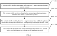
- Step 301 The vehicle obtains target status information of a target moving object at a current moment.
- the vehicle may directly perform step 301 in a traveling process to perform the step of obtaining, by the vehicle, target status information of a target moving object at a current moment; or when determining that a target condition is satisfied, the vehicle may perform the step of obtaining, by the vehicle, target status information of a target moving object at a current moment.
- the target condition in this embodiment may be that the vehicle fails to obtain road information of a current road, where the current road is a road on which the vehicle is currently located.
- the road information is used to indicate a driving status of the current road, for example, a geometric structure of the current road, a type and a position of a lane line, and a type and a position of a traffic light.
- a reason why the vehicle fails to obtain the road information may be that the vehicle fails to query a high-precision map and fails to obtain the road information.
- the high-precision electronic map provides map data with higher precision (centimeter-level precision) that is used for autonomous driving.
- a reason why the vehicle fails to obtain the road information may be that the vehicle cannot detect the road information based on the sensor layer due to a poor driving environment of the vehicle.
- the poor driving environment in this embodiment may be a case in which the vehicle travels in a night scenario, a case in which there is no lane line on the current road, or the like.
- a reason why the vehicle fails to obtain the road information may alternatively be that the vehicle fails in positioning, for example, the vehicle fails to obtain GPS positioning data.
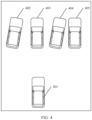
- FIG. 4 For a scenario in which the vehicle fails to obtain the road information of the current road, refer to FIG. 4 .
- a vehicle 402, a vehicle 403, a vehicle 404, and a vehicle 405 that are ahead of a vehicle 401 block lane lines of the current road, and therefore the vehicle 401 fails to obtain the road information of the current road.
- the vehicle 401 can determine a target moving object on which driving road estimation needs to be performed.
- the following describes a specific process in which the vehicle determines the target moving object.
- the target moving object is described first.
- the target moving object in this embodiment is any one of at least one moving object around the vehicle 401.
- the moving object may be an object that can affect a traveling track of the vehicle, such as a vehicle, a non-motor vehicle, or a pedestrian.
- the vehicle 401 may determine that the target moving object is a moving object ahead of the vehicle 401.
- target moving objects may be the vehicle 402, the vehicle 403, the vehicle 404, and the vehicle 405.
- the vehicle may determine target status information of the target moving object at a current moment.
- the following describes specific content included in the target status information.
- the target status information determined by the vehicle may be attribute information of the target moving object.
- the attribute information of the target moving object is used to indicate a type of the target moving object.
- the type of the target moving object in this embodiment may be a vehicle, a non-motor vehicle, a pedestrian, or the like.
- the target status information may be position information of the target moving object.
- the position information of the target moving object is position information of the target moving object in a GPS coordinate system.
- the target status information may be movement velocities of the target moving object.
- the movement velocities of the target moving object may include a lateral movement velocity Vx along an X-axis and a longitudinal movement velocity Vy along a Y-axis that are of the target moving object in the GPS coordinate system.
- the target status information may be accelerations of the target moving object.
- the accelerations of the target moving object may include a lateral acceleration ax along the X-axis and a longitudinal acceleration ay along the Y-axis that are of the target moving object in the GPS coordinate system.
- the target status information may be a movement direction ⁇ of the target moving object in the GPS coordinate system.
- status information that is corresponding to the vehicle 402 and that is obtained by the vehicle 401 may be ⁇ attribute information (type): vehicle, position information (position): (x 1 , y 1 ), movement velocity (velocity): (V x1 , V y1 ), acceleration (acceleration): (a x1 , a y1 ), movement direction (heading): ⁇ 1 ⁇ .
- type vehicle, position information (position): (x 1 , y 1 ), movement velocity (velocity): (V x1 , V y1 ), acceleration (acceleration): (a x1 , a y1 ), movement direction (heading): ⁇ 1 ⁇ .
- status information that is corresponding to the vehicle 403 and that may be obtained by the vehicle 401 is ⁇ type: vehicle, position: (x 2 , y 2 ), velocity: (V x2 , V y2 ), acceleration: (a x2 , a y2 ), heading: ⁇ 2 ⁇ ;
- status information that is corresponding to the vehicle 404 and that may be obtained by the vehicle 401 is ⁇ type: vehicle, position: (x 3 , y 3 ), velocity: (V x3 , V y3 ), acceleration: (a x3 , a y3 ), heading: ⁇ 3 ⁇ ;
- status information that is corresponding to the vehicle 405 and that may be obtained by the vehicle 401 is ⁇ type: vehicle, position: (x 4 , y 4 ), velocity: (V x4 , V y4 ), acceleration: (a x4 , a y4 ), heading: ⁇ 4 ⁇ .
- Step 302 The vehicle performs discretization processing on the target status information to obtain a parameter sequence.
- the vehicle needs to estimate the movement direction of the target moving object, and can predict a movement track of the vehicle at a subsequent moment based on the estimated movement direction of the target moving object.
- the following describes a manner in which the vehicle estimates the movement direction of the target moving object.
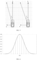
- FIG. 5 is a grid graph drawn for a vehicle for a current road on which the vehicle is located.
- radar included in the vehicle is laser radar is used for description. Because precision of the laser radar is 5 centimeters, a size of each grid of the grid graph drawn for the vehicle is 5 ⁇ 5 centimeters.
- a lateral acceleration a x and a longitudinal acceleration a y of a vehicle shown on a left side of FIG. 5 are respectively different from those of a vehicle shown on a right side of FIG. 5 . Consequently, a movement direction ⁇ i of the vehicle shown on the left side of FIG. 5 is different from a movement direction ⁇ j of the vehicle shown on the right side of FIG. 5 .
- a manner in which the vehicle performs discretization processing on the lateral acceleration of the moving object is not limited in this embodiment, provided that the lateral acceleration of the moving object that is presented as continuous data can be discretized into discrete data.
- an example in which the vehicle performs discretization processing on the lateral acceleration of the moving object in a probability discretization processing manner that is based on Gaussian distribution (gaussian distribution) is used for description.
- the vehicle may set that a lateral acceleration of the vehicle 402 satisfies a target Gaussian distribution N a x 1 ⁇ a x 1 2 shown in FIG. 6 .
- the lateral acceleration a x1 in the target Gaussian distribution is discretized into a bell-shaped region
- an expectation of the target Gaussian distribution is the lateral acceleration a x1 of the vehicle 402
- a variance of the target Gaussian distribution is ⁇ a x 1 2
- the variance ⁇ a x 1 2 represents a discrete degree of the target Gaussian distribution N a x 1 ⁇ a x 1 2
- the bell-shaped region presented by the lateral acceleration a x1 satisfying the target Gaussian distribution N a x 1 ⁇ a x 1 2 is discretized into 2( k +1) intervals shown in FIG. 6 , where k is a preset discretization coefficient.
- a specific value range of k is not limited in this embodiment.
- k in this embodiment may be inversely proportional to resolution f of a map stored in the vehicle, that is, k ⁇ 1/f, and the resolution f of the map is measured by using meters.
- a coordinate point at a central position of the bell-shaped region is C1, and a value of C1 is the lateral acceleration a x1 of the vehicle 402.
- the bell-shaped region is symmetrically distributed by using the horizontal coordinate C1 as a center, a left side of the horizontal coordinate C1 is a negative direction of the bell-shaped region, and a right side of the horizontal coordinate C 1 is a positive direction of the bell-shaped region.
- an interval P-k obtained after the lateral acceleration a x1 is discretized indicates k intervals that are on the left side of the horizontal coordinate C1 and that are in the 2( k +1) intervals obtained after the lateral acceleration a x1 is discretized; and an interval Pi obtained after the lateral acceleration a x1 is discretized indicates i intervals that are on the right side of the horizontal coordinate C1 and that are in the 2( k +1) intervals obtained after the lateral acceleration a x1 is discretized.
- the vehicle can perform sampling in a target interval to obtain a target discrete value, where the target interval is any interval included in the 2( k +1) intervals formed by the bell-shaped region that is obtained after the lateral acceleration of the vehicle 402 is discretized.
- the vehicle creates a parameter sequence based on a sampled value obtained by performing sampling in any one of the 2( k +1) intervals, where the parameter sequence includes a discrete value obtained by performing sampling in any one of the 2( k +1) intervals that are obtained after the lateral acceleration of the vehicle 402 is discretized.
- Step 303 The vehicle predicts, based on a target discrete value and the target status information, a target movement track corresponding to the target discrete value.
- the target discrete value is any one of a plurality of discrete values included in the parameter sequence.
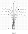
- the following describes a specific process in which the vehicle predicts the target movement track T i based on the target discrete value.
- the target movement track Ti in this embodiment includes a series of track points.
- ⁇ t represents a current moment
- ⁇ t is a predicted time step
- n ⁇ t represents a total time for the vehicle to perform forward prediction.
- a specific value of ⁇ t is not limited in this embodiment. In this embodiment, an example in which ⁇ t is any value from 3 seconds to 5 seconds is used for description.
- n is a positive integer greater than or equal to 0. Coordinates of a target track point included in the target motion track T i are ( x t 0 + n ⁇ t , y t 0 + n ⁇ t ).
- the target track point is an n th track point in a plurality of track points included in the target movement track T i . It can be learned that when the vehicle has determined coordinates of all the track points included in the target track point T i , the vehicle can determine the target movement track T i .
- the vehicle may determine the target movement track according to a fifth formula.
- the vehicle can predict any one of the 2( k +1) movement tracks, as shown in FIG. 7 .
- Step 304 The vehicle determines, based on the target movement track, a road region in which the target moving object travels at a subsequent moment.
- FIG. 8 shows a target movement track predicted by the vehicle by performing estimation on a target moving object 801.
- the vehicle can determine a road occupancy map of the target moving object 801 at the subsequent moment based on the target movement track, where the subsequent moment is a next moment of the current moment.
- an optional manner in which the vehicle determines the road occupancy map of the target moving object 801 at the subsequent moment is as follows.
- the vehicle may obtain target status information of the target moving object 801.
- the target status information in this embodiment may further include a vehicle width L of the target moving object 801.
- the vehicle may perform first preset processing on a horizontal coordinate of any track point included in the target movement track to obtain a first track point. All first track points determined by the vehicle may form a left lane boundary line of the target moving object 801 at the subsequent moment.
- the vehicle may further perform second preset processing on a vertical coordinate of any track point included in the target movement track to obtain a second track point. All second track points determined by the vehicle may form a right lane boundary line of the target moving object 801 at the subsequent moment.
- all the first track points may form a left lane boundary line 901 of the target moving object 801 at the subsequent moment.
- the left lane boundary line 901 of the target moving object 801 at the subsequent moment is x t 0 ⁇ L ⁇ sin ⁇ 1 / 2 , y t 0 + L ⁇ cos ⁇ 1 / 2 , x t 0 + ⁇ t ⁇ L ⁇ sin ⁇ 2 / 2 , y t 0 + ⁇ t + L ⁇ cos ⁇ 2 / 2 , ... , x t 0 + n ⁇ t ⁇ L ⁇ sin ⁇ n / 2 , y t 0 + n ⁇ t + L ⁇ cos ⁇ n / 2 .
- all the second track points may form a right lane boundary line 902 of the target moving object 801 at the subsequent moment.
- the right lane boundary line 902 of the target moving object 801 at the subsequent moment is x t 0 ⁇ L ⁇ sin ⁇ 1 / 2 , y t 0 ⁇ L ⁇ cos ⁇ 1 / 2 , x t 0 + ⁇ t + L ⁇ sin ⁇ 2 / 2 , y t 0 + ⁇ t ⁇ L ⁇ cos ⁇ 2 / 2 , ...
- the vehicle may form the road occupancy map of the target moving object 801 at the subsequent moment based on the determined left lane boundary line and right lane boundary line.
- the vehicle determines that the target movement track is a lane central axis of the road occupancy map of the target moving object 801 at the subsequent moment. In this case, when the vehicle has determined the lane central axis of the road occupancy map of the target moving object 801 at the subsequent moment, the vehicle can determine the road occupancy map of the target moving object 801 at the subsequent moment.
- the vehicle may determine road occupancy maps of all moving objects ahead of the vehicle at the subsequent moment, and in this case, the vehicle can estimate the road region in which the target moving object travels at the subsequent moment.
- a specific extension direction of the road region is not limited in this embodiment.
- the vehicle may obtain road regions in which the target moving object 402, the target moving object 403, the target moving object 404, and the target moving object 405 travel at the subsequent moment.
- the vehicle can estimate a road region in which the vehicle travels at the subsequent moment.
- the road region in which the vehicle travels at the subsequent moment is not limited in this embodiment, provided that the road region in which the vehicle travels at the subsequent moment does not overlap the estimated road region in which the target moving object travels at the subsequent moment.
- the road region in which the vehicle travels at the subsequent moment does not overlap the road region in which the target moving object 402 travels at the subsequent moment, the road region in which the target moving object 403 travels at the subsequent moment, the road region in which the target moving object 404 travels at the subsequent moment, and the road region in which the target moving object 405 travels at the subsequent moment.
- This ensures that the vehicle does not collide with the target moving object 402, the target moving object 403, the target moving object 404, and the target moving object 405 in a traveling scenario at the subsequent moment, thereby implementing safe driving.
- the vehicle obtains the target status information of the target moving object at the current moment; the vehicle directly performs, without relying on a current driving environment, discretization processing on the target status information to obtain the parameter sequence, and then can obtain the target movement track based on the parameter sequence; and the vehicle can estimate, by performing calculation on the target movement track, the road region in which the vehicle travels at the subsequent moment. In a process of obtaining the road region, the vehicle does not need to rely on a driving environment.
- the vehicle can accurately estimate the road region in which the vehicle travels, without tracking the target moving object, thereby improving accuracy and robustness of estimating the road region in which the vehicle travels at the subsequent moment. This provides a safety assurance for autonomous driving.
- the vehicle may predict, based on the embodiment in FIG. 3 , a road occupancy map of each target moving object at a subsequent moment.
- a road occupancy map of each target moving object may be predicted, based on the embodiment in FIG. 3 .
- FIG. 10 the following describes a specific process of improving accuracy of a road region, predicted by a vehicle, at a subsequent moment.
- Step 1001 The vehicle obtains target status information of a target moving object at a current moment.
- step 301 shown in FIG. 3 For details about a specific execution process of step 1001 in this embodiment, refer to step 301 shown in FIG. 3 . The details are not described in this embodiment again.
- Step 1002 The vehicle performs discretization processing on the target status information to obtain a parameter sequence.
- the parameter sequence includes a target discrete value obtained by performing sampling in any one of 2( k +1) intervals obtained after a lateral acceleration of the target moving object is discretized.
- the parameter sequence in this embodiment further includes a target probability value corresponding to the target discrete value.
- a specific process is as follows.
- a target probability value corresponding to the target discrete value obtained by the vehicle through sampling in the target interval is equal to a target probability value corresponding to the target interval. It can be learned that when determining the target probability value corresponding to the target interval, the vehicle can determine the target probability value that is corresponding to the target discrete value and that is equal to the target probability value corresponding to the target interval.
- the following describes, by using an example, a specific process in which the vehicle obtains the target probability value corresponding to the target interval.
- the vehicle may calculate, by calculating the area of the target interval, the target probability value corresponding to the target interval.
- a specific process in which the vehicle calculates the area of the target interval is as follows.
- the vehicle can determine that the target probability value corresponding to the target discrete value obtained by sampling in the target interval is also P i .
- the vehicle can create a parameter sequence, where the parameter sequence includes a discrete value obtained by performing sampling in any one of 2( k +1) intervals obtained after a lateral acceleration of the vehicle 402 is discretized and a corresponding target probability value.
- Step 1003 The vehicle predicts, based on the target discrete value and the target status information, a target movement track corresponding to the target discrete value.
- step 1003 For details about a specific execution process of step 1003 in this embodiment, refer to step 303 shown in FIG. 3 . The specific execution process is not described again in this embodiment.
- Step 1004 The vehicle performs, according to a sixth formula, attenuation processing on a target probability value corresponding to the target track point, to obtain a target probability value after the attenuation processing.
- FIG. 8 is used as an example. Accuracy of a track point included in the target movement track that is obtained by the vehicle by performing prediction on the target moving object is gradually reduced with time. If the accuracy of the track point estimated by the vehicle is higher, it indicates that a probability that the track point belongs to a road region in which the target moving object travels at the subsequent moment is higher. If the accuracy of the track point estimated by the vehicle is lower, it indicates that a probability that the track point belongs to the road region in which the target moving object travels at the subsequent moment is lower.
- accuracy of estimating a track point ( x t0+n ⁇ t , y t 0 +n ⁇ t ) by the vehicle is lower than accuracy of estimating a track point ( x t 0 +n ⁇ t , y t 0 +n ⁇ t ) by the vehicle.
- the vehicle may perform attenuation processing on the target track point included in the predicted target movement track.
- the following describes in detail a specific process of performing attenuation processing on the target track point by the vehicle.
- the vehicle may first query the parameter sequence for a target probability value corresponding to the target track point. Specifically, the vehicle may obtain a target movement track to which the target track point belongs, so as to determine a target probability value P, that is corresponding to the target movement track and that is in the parameter sequence.
- the vehicle can perform, according to the sixth formula, attenuation processing on the target probability value P, corresponding to the target track point ( x t 0 + n ⁇ t , y t 0 +n ⁇ t ) to obtain a target probability value P ( x t 0 +n ⁇ t , y t 0 +n ⁇ t ) after the attenuation processing.
- a specific value of A is not limited in this embodiment. Specifically, to perform attenuation for a track point included in a target track line, A in this embodiment may be any value from 0 to 1.
- the vehicle may determine that the target probability value corresponding to the target track point is the target probability value P(x t 0 +n ⁇ t , y t 0 +n ⁇ t ) obtained after the attenuation processing.
- the vehicle can perform attenuation processing on a target probability value corresponding to coordinates of each track point included in the target movement track of the target moving object.
- the vehicle performs attenuation processing on a probability of any track point included in the target movement track, to effectively improve accuracy of the any track point included in the target movement track.
- the track point predicted by the vehicle can more accurately reflect a movement track of the target moving object at the subsequent moment.
- the vehicle predicts the movement track of the moving object at the subsequent moment, there is a target track point that satisfies a first preset condition.
- a target track point that satisfies the first preset condition.
- the vehicle may obtain a first probability value and a second probability value that are corresponding to the intersection point 1105. If the vehicle has performed attenuation processing on the first target movement track 1103 based on the foregoing description, the first probability value is a target probability value that is corresponding to the intersection point 1105 in the first target movement track 1103 and that is obtained after the vehicle performs attenuation processing on the first target movement track 1103.
- the second probability value is a target probability value that is corresponding to the intersection point 1105 in the second target movement track 1104 and that is obtained after the vehicle performs attenuation processing on the second target movement track 1104.
- the first probability value is a target probability value corresponding to the first target movement track 1103 of the vehicle
- the second probability value is a target probability value corresponding to the second target movement track 1104 of the vehicle.
- the vehicle may determine the first probability value P i ( x t 0 +n1 ⁇ t , y t 0 +n1 ⁇ t ) and the second probability value P j (x t 0 +n2 ⁇ t , y t 0 + n 2 ⁇ t ) that are corresponding to the intersection point 1105.
- P (x, y) max(( P i ( x t 0 +n1 ⁇ t ,y t 0 +n1 ⁇ t ), P j ( x t
- the target track point is an intersection point between two movement tracks.
- the target track point may alternatively be an intersection point among more than two movement tracks, provided that the vehicle can determine a probability value corresponding to the target track point in each of the plurality of movement tracks to determine a maximum value among a plurality of probability values as the target probability value.
- the vehicle may correct, based on a historical movement track, a target probability value of a track point included in the target movement track, to improve accuracy of an obtained target probability value.
- the vehicle may perform a process of correcting, based on the historical movement track, the target probability value of the track point included in the target movement track.
- FIG. 7 is a schematic diagram of distribution of 2( k +1) movement tracks obtained by the vehicle by performing prediction on the target moving object at the current moment, and the vehicle further has stored 2( k +1) historical movement tracks obtained by performing prediction on the target moving object at a historical moment, where the historical moment is a previous moment of the current moment.
- the vehicle can perform overlay processing on a probability value of any track point included in the target movement track predicted at the current moment and the historical movement track predicted at the historical moment, to obtain the target probability value corresponding to the target track point, so as to improve accuracy of the target probability value corresponding to the target track point predicted by the vehicle.
- Step 1005 The vehicle obtains a target track point that satisfies a regression fitting condition.
- the vehicle may determine, by using step 1004, a target probability value corresponding to any track point (target track point) included in the target movement track. If the target probability value is larger, it indicates that the target track point is more likely to belong to the road region of the target moving object at the subsequent moment; and if the target probability value is smaller, it indicates that the target track point is less likely to belong to the road region of the target moving object at the subsequent moment.
- the vehicle may perform filtering on each track point included in the target movement track. In this way, a track point that is more likely to belong to the road region is reserved.
- the following describes a manner in which the vehicle performs filtering on each track point included in the target movement track.
- the vehicle When the vehicle obtains a target probability value corresponding to a target track point, and if the target probability value is greater than or equal to a preset probability value, the vehicle determines that the target track point satisfies the regression fitting condition, where the target track point that satisfies the regression fitting condition is used to estimate the road region in which the target moving object travels at the subsequent moment; or if the target probability value is less than a preset probability value, the vehicle may determine that the target track point does not satisfy the regression fitting condition, so that the target track point that does not satisfy the regression fitting condition is not used to estimate the road region in which the target moving object travels at the subsequent moment.
- a specific value of the preset probability value P threshold is not limited in this embodiment, provided that the target track point corresponding to the target probability value belongs to the road region when the target probability value is greater than or equal to the preset probability value P threshold .
- coordinates of the target track point are (x, y).
- the target probability value corresponding to the target track point satisfies P(x, y) ⁇ P threshold
- the target track point (x, y) satisfies the regression fitting condition
- the target track point (x, y) does not satisfy the regression fitting condition.
- Step 1006 The vehicle performs regression fitting based on the target track point that satisfies the regression fitting condition, to obtain the road region in which the target moving object travels at the subsequent moment.
- a target movement track obtained after the filtering may be as follows.
- T i ⁇ (x sample 1 ,y sample 1 ),(x sample2 ,y sample 2 ),...,(x samplek ,y samplek ),...,(x samplen ,y samplen ) ⁇ where 1 ⁇ k ⁇ n , a track point ( x sample 1 , y sample1 ), a track point (x sample2 ,y sample2 ) , ..., and a track point ( x samplen ,y samplen ) included in the target movement track all satisfy the regression fitting condition. It can be learned that the track points included in the target movement track obtained after the vehicle performs filtering on the target movement track are relatively dispersedly distributed.
- the vehicle cannot estimate, based on the scattered target track points included in the target movement track, a road region in which the vehicle can travel. Therefore, to improve accuracy of the road region in which the vehicle can travel and that is estimated by the vehicle, the vehicle may process, by using a regression fitting method, the track points that are included in the target movement track and that satisfy the regression fitting condition.
- the following describes, by using an example, a manner in which the vehicle performs regression fitting on the track points that are included in the target movement track and that satisfy the regression fitting condition.
- a specific regression fitting manner is not limited in this embodiment, provided that the vehicle can predict a target reference line based on the target movement track, making the vehicle predict, based on the target reference line, the road region in which the target moving object travels at the subsequent moment.
- a generalized regression neural network general regression neural network, GRNN
- regression fitting is performed, by using the GRNN, on the scattered track points included in the target movement track to form the target reference line.
- the vehicle may train, based on a GRNN network structure shown in FIG. 13 , the track points that are included in the target movement track and that satisfy the regression fitting condition, to obtain the target reference line.
- the GRNN in this embodiment uses, as learning samples, the track points that are included in the target movement track and that satisfy the regression fitting condition. Because the GRNN has a quite strong nonlinear mapping capability, a regression effect is still quite good when there is a small amount of sample data. Therefore, accuracy of a predicted movement track of the target moving object at the subsequent moment can be improved by using the GRNN.
- the GRNN network structure in this embodiment includes four layers of networks.
- a first layer of network is an input layer 1301, a second layer of network is a pattern layer 1302, a third layer of network is a summation layer 1303, and a fourth layer of network is an output layer 1304.
- the vehicle may generate an input vector.
- An element included in the input vector in this embodiment is a horizontal coordinate x sample k of a target track point included in the target movement track, and a dimension of the input vector is 1.
- the pattern layer 1302 includes a plurality of pattern layer neurons, and a quantity of pattern layer neurons included at the pattern layer 1302 is equal to a quantity of track points included in the target movement track.
- the target movement track in this embodiment includes n track points, and in this case, the pattern layer 1302 also includes n pattern layer neurons.
- the vehicle creates a correspondence between different pattern layer neurons and different track points included in the target movement track, so that the input layer 1301 can input any element included in the input vector to a corresponding pattern layer neuron.
- the vehicle may input any element x sample k included in the input vector to a k th pattern layer neuron included at the pattern layer 1302, and the k th pattern layer neuron performs calculation on x sample k by using a pattern neuron transfer function, to obtain a pattern neuron output parameter p k .
- x i with different values may be selected for the pattern neuron transfer function for different pattern layer neurons in this embodiment.
- the vehicle may input, to both a first summation neuron and a second summation neuron, a pattern neuron output parameter that is output by any pattern layer neuron included at the pattern layer 1302.
- the second summation neuron in this embodiment may perform weighted summation on the output parameters p k output by all the pattern layer neurons, where M2 is a connection weight between the second summation neuron and each pattern layer neuron.
- M2 is a connection weight between the second summation neuron and each pattern layer neuron.
- the connection weighted value M2 of the second summation neuron is a vertical coordinate of each track point included in the target movement track is used for description.
- a coordinate point sequence may be output, where the coordinate point sequence includes a plurality of coordinate points (x 1 , y 1 ), (x 2 , y 2 ), ..., and (x n , y n ).
- the vehicle can determine that a track line formed by the coordinate point sequence is the target reference line, so that the vehicle can determine, based on the target reference line, the road region in which the target moving object travels at the subsequent moment.
- the vehicle obtains the target status information of the target moving object at the current moment; the vehicle directly performs, without relying on a current driving environment, discretization processing on the target status information to obtain the parameter sequence, and then can obtain the target movement track based on the parameter sequence; and the vehicle can estimate, by performing calculation on the target movement track, the road region in which the vehicle travels at the subsequent moment.
- each target probability value is multiplied by a corresponding time attenuation factor ⁇ , so as to obtain a relatively accurate road region of the target moving object at the subsequent moment.
- the vehicle performs estimation based on the road region of the target moving object at the subsequent moment, to accurately obtain the road region of the vehicle at the subsequent moment, thereby improving accuracy and robustness of estimating the road region in which the vehicle travels at the subsequent moment. This provides a safety assurance for autonomous driving.
- the driving road estimation system includes an obtaining unit 141, a processing unit 142, a prediction unit 143, and a determining unit 144.
- the obtaining unit 141 is configured to obtain target status information of a target moving object at a current moment, where the target moving object is any one of at least one moving object around the vehicle, and the target status information includes a lateral acceleration of the target moving object.
- the processing unit 142 is configured to perform discretization processing on the target status information to obtain a parameter sequence, where the parameter sequence includes a plurality of discrete values.
- the processing unit 142 includes:
- the prediction unit 143 is configured to predict, based on the target discrete value and the target status information, a target movement track corresponding to the target discrete value, where the target discrete value is any one of the plurality of discrete values included in the parameter sequence.
- the determining unit 144 is configured to determine, based on the target movement track, a road region in which the target moving object travels at a subsequent moment.
- the driving road estimation system can predict a road occupancy map of each target moving object at the subsequent moment.
- the following describes a specific process in which the driving road estimation system improves accuracy of a road region, predicted by the driving road estimation system, at a subsequent moment.
- the driving road estimation system includes an obtaining unit 151, a processing unit 152, a prediction unit 153, and a determining unit 154.
- the obtaining unit 151 is configured to obtain target status information of a target moving object at a current moment, where the target moving object is any one of at least one moving object around a vehicle, and the target status information includes a lateral acceleration of the target moving object.
- the processing unit 152 is configured to perform discretization processing on the target status information to obtain a parameter sequence, where the parameter sequence includes a plurality of discrete values.
- the processing unit 152 includes a first obtaining module 1521, a sampling module 1522, a second obtaining module1523, and a setting module 1524.
- the first obtaining module 1521 is configured to set that the target status information satisfies a target Gaussian distribution N a x1 ⁇ a x1 2 , where an expectation of the target Gaussian distribution is the lateral acceleration a x1 , a variance of the target Gaussian distribution is ⁇ a x1 2 , and the variance ⁇ a x1 2 represents a discrete degree of the target Gaussian distribution N a x1 ⁇ a x1 2 ; and the target status information satisfying the target Gaussian distribution N a x1 ⁇ a x1 2 is discretized into 2( k +1) intervals, where k is a preset discretization coefficient.
- the sampling module 1522 is configured to perform sampling in a target interval to obtain a target discrete value, where the target interval is any one of the 2( k +1) intervals obtained after discretization.
- the second obtaining module 1523 is configured to obtain a target probability value corresponding to the target discrete value, where the target probability value corresponding to the target discrete value is equal to an area of the target interval.
- the second obtaining module 1523 specifically includes:
- the setting module 1524 is configured to set the target discrete value and the target probability value corresponding to the target discrete value in the parameter sequence.
- the prediction unit 153 is configured to predict, based on the target discrete value and the target status information, a target movement track corresponding to the target discrete value, where the target discrete value is any one of the plurality of discrete values included in the parameter sequence.
- the prediction unit 143 is specifically configured to: determine, according to a fifth formula, coordinates ( x t 0 + n ⁇ t ,y t 0 + n ⁇ t ) of a target track point included in the target movement track, where the target track point is an n th track point in a plurality of track points included in the target movement track, t 0 is the current moment, ⁇ t is a predicted time step, and n is a positive integer greater than or equal to 0;
- the determining unit 154 is configured to determine, based on the target movement track, a road region in which the target moving object travels at a subsequent moment.
- the determining unit 154 includes a first determining module 1541, a second determining module 1542, and a third determining module 1543.
- the first determining module 1541 is configured to obtain a target probability value corresponding to the target track point included in the target movement track, where the target probability value corresponding to the target track point is equal to the target probability value corresponding to the target discrete value.
- the first determining module 1541 specifically includes:
- the first determining module 1541 specifically includes:
- the first determining module 1541 further includes:
- the second determining module 1542 is configured to obtain a target track point that satisfies a regression fitting condition, where the target track point that satisfies the regression fitting condition is a track point corresponding to a target probability value greater than or equal to a preset probability value.
- the third determining module 1543 is configured to perform regression fitting based on the target track point that satisfies the regression fitting condition, to obtain the road region in which the target moving object travels at the subsequent moment.
- the computer-readable storage medium includes an instruction.
- the central processing unit When the instruction is run on the central processing unit shown in FIG. 2 , the central processing unit is enabled to perform the methods shown in FIG. 3 and FIG. 10 . Specific execution processes are not described again.
- This application further provides a computer program product including an instruction.
- the central processing unit shown in FIG. 2
- the central processing unit is enabled to perform the methods shown in FIG. 3 and FIG. 10 . Specific execution processes are not described again.
- the disclosed system, apparatus, and method may be implemented in other manners.
- the described apparatus embodiment is merely an example.
- the unit division is merely logical function division and may be other division in actual implementation.
- a plurality of units or components may be combined or integrated into another system, or some features may be ignored or not performed.
- the displayed or discussed mutual couplings or direct couplings or communication connections may be implemented by using some interfaces.
- the indirect couplings or communication connections between the apparatuses or units may be implemented in electronic, mechanical, or other forms.
- the units described as separate parts may or may not be physically separate, and parts displayed as units may or may not be physical units, may be located in one position, or may be distributed on a plurality of network units. Some or all of the units may be selected based on actual requirements to achieve the objectives of the solutions of the embodiments.
- functional units in the embodiments of the present invention may be integrated into one processing unit, or each of the units may exist alone physically, or two or more units are integrated into one unit.
- the integrated unit may be implemented in a form of hardware, or may be implemented in a form of a software functional unit.
- the integrated unit When the integrated unit is implemented in the form of a software functional unit and sold or used as an independent product, the integrated unit may be stored in a computer-readable storage medium. Based on such an understanding, the technical solutions of the present invention essentially, or the part contributing to the prior art, or all or some of the technical solutions may be implemented in the form of a software product.
- the software product is stored in a storage medium and includes several instructions for instructing a computer device (which may be a personal computer, a server, or a network device) to perform all or some of the steps of the methods described in the embodiments of the present invention.
- the foregoing storage medium includes: any medium that can store program code, such as a USB flash drive, a removable hard disk, a read-only memory (Read-Only Memory, ROM), a random access memory (Random Access Memory, RAM), a magnetic disk, or an optical disc.
- program code such as a USB flash drive, a removable hard disk, a read-only memory (Read-Only Memory, ROM), a random access memory (Random Access Memory, RAM), a magnetic disk, or an optical disc.
Landscapes
- Engineering & Computer Science (AREA)
- Radar, Positioning & Navigation (AREA)
- Remote Sensing (AREA)
- Automation & Control Theory (AREA)
- Physics & Mathematics (AREA)
- General Physics & Mathematics (AREA)
- Human Computer Interaction (AREA)
- Transportation (AREA)
- Mechanical Engineering (AREA)
- Traffic Control Systems (AREA)
- Control Of Driving Devices And Active Controlling Of Vehicle (AREA)
Claims (15)
- Verfahren zum Vorhersagen einer Wegbelegungskarte eines sich bewegenden Zielobjektes, umfassend:Erlangen (301) von Zielstatusinformationen des sich bewegenden Zielobjektes zu einem aktuellen Zeitpunkt, wobei das sich bewegende Zielobjekt ein beliebiges von mindestens einem sich bewegenden Objekt um ein Fahrzeug herum ist und die Zielstatusinformationen eine Querbeschleunigung des sich bewegenden Zielobjektes umfassen;Durchführen (302) einer Diskretisierungsverarbeitung an den Zielstatusinformationen, um eine Parameterfolge zu erlangen, wobei die Parameterfolge eine Vielzahl von diskreten Werten umfasst;Vorhersagen (303), basierend auf einem diskreten Zielwert und den Zielstatusinformationen, einer Zielbewegungsspur, die dem diskreten Zielwert entspricht, wobei der diskrete Zielwert ein beliebiger der Vielzahl von diskreten Werten ist, die in der Parametersequenz enthalten sind, und die Zielbewegungsspur eine Vielzahl von Zielspurpunkten umfasst;Bestimmen (304), basierend auf der Zielbewegungsspur, eines Wegbereiches, in dem sich das sich bewegende Zielobjekt zu einem nachfolgenden Zeitpunkt bewegt, wobei der nachfolgende Zeitpunkt ein Zeitpunkt nach dem aktuellen Zeitpunkt ist;dadurch gekennzeichnet, dass das Bestimmen Folgendes umfasst:Erlangen eines Zielwahrscheinlichkeitswertes, der jedem in der Zielbewegungsspur enthaltenen Zielspurpunkt entspricht, wobei der Zielwahrscheinlichkeitswert, der dem Zielspurpunkt entspricht, gleich dem Zielwahrscheinlichkeitswert ist, der dem diskreten Zielwert entspricht;Erlangen eines Zielspurpunkts, der eine Regressionsanpassungsbedingung erfüllt, wobei der Zielspurpunkt, der die Regressionsanpassungsbedingung erfüllt, ein Spurpunkt ist, der einem Zielwahrscheinlichkeitswert entspricht, welcher größer als oder gleich einem zuvor festgelegten Wahrscheinlichkeitswert ist; undDurchführen einer Regressionsanpassung basierend auf dem Zielspurpunkt, der die Regressionsanpassungsbedingung erfüllt, um den Wegbereich zu erlangen, in dem sich das sich bewegende Zielobjekt zu dem nächsten Zeitpunkt bewegt.
- Verfahren nach Anspruch 1, wobei das Durchführen einer Diskretisierungsverarbeitung an den Zielstatusinformationen, um eine Parameterfolge zu erlangen, Folgendes umfasst:Festlegen, dass die Zielstatusinformationen eine Zielnormalverteilung


 Durchführen einer Abtastung in einem Zielintervall, um den diskreten Zielwert zu erlangen, wobei das Zielintervall ein beliebiges der 2(k+1) Intervalle ist, die nach der Diskretisierung erlangt werden;Erlangen eines Zielwahrscheinlichkeitswertes, der dem diskreten Zielwert entspricht, wobei der Zielwahrscheinlichkeitswert, der dem diskreten Zielwert entspricht, gleich einer Fläche des Zielintervalls ist; undFestlegen des diskreten Zielwertes und des Zielwahrscheinlichkeitswertes, der dem diskreten Zielwert in der Parametersequenz entspricht.
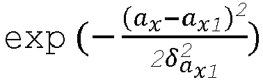
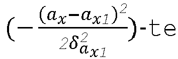
 - Schätzverfahren nach Anspruch 2, wobei, wenn die Zielstatusinformationen ferner eine Längsbeschleunigung ay1 des sich bewegenden Zielobjektes umfassen und das Zielintervall ein i-tes Intervall in den 2(k+1) Intervallen ist, das Erlangen eines Zielwahrscheinlichkeitswertes, der dem diskreten Zielwert entspricht, Folgendes umfasst:wenn i eine beliebige ganze Zahl größer als 0 und kleiner als oder gleich k ist, Bestimmen des Zielwahrscheinlichkeitswertes Pi, der dem diskreten Zielwert entspricht, gemäß einer ersten Formel, wobei die erste Formel folgendermaßen lautet:

x1 , ax1 +(i-1)*δax1 ] ist, eine Integralvariable ax ist, ein Integrand
 wenn i eine beliebige ganze Zahl größer als -k und kleiner als 0 ist, Bestimmen des Zielwahrscheinlichkeitswertes Pi , der dem diskreten Zielwert entspricht, gemäß einer zweiten Formel, wobei die zweite Formel folgendermaßen lautet:

x1 , ax1 +i*δax1 ] ist, eine Integralvariable ax ist, ein Integrand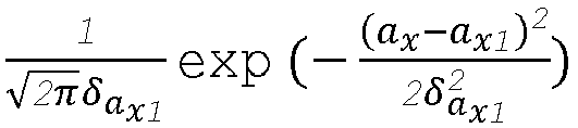

 wenn i gleich -k-1 ist, Bestimmen des Zielwahrscheinlichkeitswertes Pi, der dem diskreten Zielwert entspricht, gemäß einer dritten Formel, wobei die dritte Formel folgendermaßen lautet:


x1 , a xmin] ist, eine Integralvariable ax ist, ein Integrand

 wenn i gleich k+1 ist, Bestimmen des Zielwahrscheinlichkeitswertes Pi, der dem diskreten Zielwert entspricht, gemäß einer vierten Formel, wobei die vierte Formel folgendermaßen lautet:


x1 ] ist, eine Integralvariable ax ist, ein Integrand

- Verfahren nach einem der Ansprüche 1 bis 3, wobei, wenn die Zielstatusinformationen ferner eine Quergeschwindigkeit vx1 des sich bewegenden Zielobjektes und eine Längsgeschwindigkeit vy1 des sich bewegenden Zielobjektes umfassen, das Vorhersagen, basierend auf einem diskreten Zielwert und den Zielstatusinformationen, einer Zielbewegungsspur, die dem diskreten Zielwert entspricht, Folgendes umfasst:Bestimmen von Koordinaten (x t
0 +nΔ t,y t0 +nΔt ) eines in der Zielbewegungsspur enthaltenen Zielspurpunkts gemäß der fünften Formel, wobei der Zielspurpunkt ein n-ter Spurpunkt in einer Vielzahl von in der Zielbewegungsspur enthaltenen Spurpunkten ist, t0 der aktuelle Zeitpunkt ist, Δt ein vorhergesagter Zeitschritt ist und n eine positive ganze Zahl größer als oder gleich 0 ist;wobei die fünfte Formel
 ay1 die in den Zielstatusinformationen enthaltene Längsbeschleunigung des sich bewegenden Zielobjektes ist, und ax_Abtastung [i] der diskrete Zielwert ist.
 - Verfahren nach Anspruch 1, wobei das Erlangen eines Zielwahrscheinlichkeitswertes, der dem in der Zielbewegungsspur enthaltenen Zielspurpunkt entspricht, ferner Folgendes umfasst:Durchführen einer Dämpfungsverarbeitung an einem Zielwahrscheinlichkeitswert Pi, der dem Zielspurpunkt (x t
0 +nΔ t,y t0 +nΔt ) entspricht, gemäß einer sechsten Formel, um nach der Dämpfungsverarbeitung einen Zielwahrscheinlichkeitswert P(x t0 +nΔt,y t0 +nΔt ) zu erlangen, wobei die sechste Formel P(x t0 +nΔ t,y t0 +nΔt ) = λn * Pi lautet und λ ein zuvor festgelegter Wert ist; undBestimmen, dass der Zielwahrscheinlichkeitswert, der dem Zielspurpunkt entspricht, der Zielwahrscheinlichkeitswert P(x t0 +nΔ t,y t0 +nΔt ) ist, der nach der Dämpfungsverarbeitung erlangt wird. - Verfahren nach Anspruch 1, wobei das Erlangen eines Zielwahrscheinlichkeitswertes, der dem in der Zielbewegungsspur enthaltenen Zielspurpunkt entspricht, ferner Folgendes umfasst:wenn der Zielspurpunkt, der eine erste zuvor festgelegte Bedingung erfüllt, erlangt wird, Erlangen einer Vielzahl von Wahrscheinlichkeitswerten, die dem Zielspurpunkt entsprechen, wobei die erste zuvor festgelegte Bedingung darin besteht, dass sich der Zielspurpunkt in unterschiedlichen Bewegungsspuren befindet; undBestimmen eines maximalen Wertes von Wahrscheinlichkeitswerten, die dem Zielspurpunkt in den unterschiedlichen Bewegungsspuren entsprechen, als den Zielwahrscheinlichkeitswert, der dem Zielspurpunkt entspricht.
- Verfahren nach Anspruch 1, wobei das Erlangen eines Zielwahrscheinlichkeitswertes, der dem in der Zielbewegungsspur enthaltenen Zielspurpunkt entspricht, ferner Folgendes umfasst:Erlangen einer historischen Bewegungsspur, die für das sich bewegende Zielobjekt zu einem historischen Zeitpunkt vorhergesagt wurde, wobei der historische Zeitpunkt ein Zeitpunkt vor dem aktuellen Zeitpunkt ist;wenn der Zielspurpunkt, der eine zweite zuvor festgelegte Bedingung erfüllt, erlangt wird, Erlangen eines ersten Wahrscheinlichkeitswertes und eines zweiten Wahrscheinlichkeitswertes, die dem Zielspurpunkt entsprechen, wobei die zweite zuvor festgelegte Bedingung darin besteht, dass sich der Zielspurpunkt sowohl in der Zielbewegungsspur als auch in der historischen Bewegungsspur befindet, der erste Wahrscheinlichkeitswert ein Wahrscheinlichkeitswert ist, der dem Zielspurpunkt entspricht und der durch Durchführen einer Vorhersage an dem sich bewegenden Zielobjekt zu dem aktuellen Zeitpunkt erlangt wird, und der zweite Wahrscheinlichkeitswert ein Wahrscheinlichkeitswert ist, der dem Zielspurpunkt entspricht und der durch Durchführen einer Vorhersage an dem sich bewegenden Zielobjekt zu dem historischen Zeitpunkt erlangt wird; undBestimmen des größeren von dem ersten Wahrscheinlichkeitswert und dem zweiten Wahrscheinlichkeitswert als den Zielwahrscheinlichkeitswert, der dem Zielspurpunkt entspricht.
- System zum Vorhersagen einer Wegbelegungskarte eines sich bewegenden Zielobjektes, umfassend:eine Erlangungseinheit (141), die dazu konfiguriert ist, Zielstatusinformationen des sich bewegenden Zielobjektes zu einem aktuellen Zeitpunkt zu erlangen, wobei das sich bewegende Zielobjekt ein beliebiges von mindestens einem sich bewegenden Objekt um ein Fahrzeug herum ist und die Zielstatusinformationen eine Querbeschleunigung des sich bewegenden Zielobjektes umfassen;eine Durchführungseinheit (142), die dazu konfiguriert ist, eine Diskretisierungsverarbeitung an den Zielstatusinformationen durchzuführen, um eine Parameterfolge zu erlangen, wobei die Parameterfolge eine Vielzahl von diskreten Werten umfasst;eine Vorhersageeinheit (143), die dazu konfiguriert ist, basierend auf einem diskreten Zielwert und den Zielstatusinformationen eine Zielbewegungsspur vorherzusagen, die dem diskreten Zielwert entspricht, wobei der diskrete Zielwert ein beliebiger der Vielzahl von diskreten Werten ist, die in der Parametersequenz enthalten sind, und die Zielbewegungsspur eine Vielzahl von Zielspuren umfasst;eine Bestimmungseinheit (144), die dazu konfiguriert ist, basierend auf der Zielbewegungsspur einen Wegbereich zu bestimmen, in dem sich das sich bewegende Zielobjekt zu einem nachfolgenden Zeitpunkt bewegt, wobei der nachfolgende Zeitpunkt ein Zeitpunkt nach dem aktuellen Zeitpunkt ist;dadurch gekennzeichnet, dass die Bestimmungseinheit Folgendes umfasst:ein erstes Bestimmungsmodul, das dazu konfiguriert ist, einen Zielwahrscheinlichkeitswert zu erlangen, der jedem in der Zielbewegungsspur enthaltenen Zielspurpunkt entspricht, wobei der Zielwahrscheinlichkeitswert, der dem Zielspurpunkt entspricht, gleich dem Zielwahrscheinlichkeitswert ist, der dem diskreten Zielwert entspricht;ein zweites Bestimmungsmodul, das dazu konfiguriert ist, einen Zielspurpunkt zu erlangen, der eine Regressionsanpassungsbedingung erfüllt, wobei der Zielspurpunkt, der die Regressionsanpassungsbedingung erfüllt, ein Spurpunkt ist, der einem Zielwahrscheinlichkeitswert entspricht, welcher größer als oder gleich einem zuvor festgelegten Wahrscheinlichkeitswert ist; undein drittes Bestimmungsmodul, das dazu konfiguriert ist, eine Regressionsanpassung basierend auf dem Zielspurpunkt, der die Regressionsanpassungsbedingung erfüllt, durchzuführen, um den Wegbereich zu erlangen, in dem sich das sich bewegende Zielobjekt zu dem nächsten Zeitpunkt bewegt.
- Fahrwegschätzsystem nach Anspruch 8, wobei die Verarbeitungseinheit Folgendes umfasst:ein erstes Erlangungsmodul, das dazu konfiguriert ist, festzulegen, dass die Zielstatusinformationen eine Zielnormalverteilung


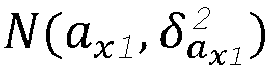
 ein Abtastmodul, das dazu konfiguriert ist, eine Abtastung in einem Zielintervall durchzuführen, um den diskreten Zielwert zu erlangen, wobei das Zielintervall ein beliebiges der 2(k+1) Intervalle ist, die nach der Diskretisierung erlangt werden;ein zweites Erlangungsmodul, das dazu konfiguriert ist, einen Zielwahrscheinlichkeitswert zu erlangen, der dem diskreten Zielwert entspricht, wobei der Zielwahrscheinlichkeitswert, der dem diskreten Zielwert entspricht, gleich einer Fläche des Zielintervalls ist; undein Festlegungsmodul, das dazu konfiguriert ist, den diskreten Zielwert und den Zielwahrscheinlichkeitswert, der dem diskreten Zielwert in der Parametersequenz entspricht, festzulegen.
 - Fahrwegschätzsystem nach Anspruch 9, wobei, wenn die Zielstatusinformationen ferner die Längsbeschleunigung ay1 des sich bewegenden Zielobjektes umfassen und das Zielintervall ein i-tes Intervall in den 2(k+1) Intervallen ist, das zweite Erlangungsmodul spezifisch Folgendes umfasst:ein erstes Berechnungsuntermodul, das zu Folgendem konfiguriert ist: wenn i eine beliebige ganze Zahl größer als 0 und kleiner als oder gleich k ist, Bestimmen des Zielwahrscheinlichkeitswertes Pi, der dem diskreten Zielwert entspricht, gemäß einer ersten Formel, wobei die erste Formel folgendermaßen lautet:

x1 , ax1 + (i - 1) *δax1 ] ist, eine Integralvariable ax ist, ein Integrand

 ein zweites Berechnungsuntermodul, das zu Folgendem konfiguriert ist: wenn i eine beliebige ganze Zahl größer als -k und kleiner als 0 ist, Bestimmen des Zielwahrscheinlichkeitswertes Pi , der dem diskreten Zielwert entspricht, gemäß einer zweiten Formel, wobei die zweite Formel folgendermaßen lautet:

x1 , ax1 + i *δax1 ] ist, eine Integralvariable ax ist, ein Integrand

 ein drittes Berechnungsuntermodul, das zu Folgendem konfiguriert ist: wenn i gleich -k-1 ist, Bestimmen des Zielwahrscheinlichkeitswertes Pi, der dem diskreten Zielwert entspricht, gemäß einer dritten Formel, wobei die dritte Formel folgendermaßen lautet:

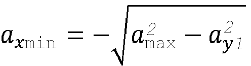
x1 , a xmin] ist, eine Integralvariable ax ist, ein Integrand

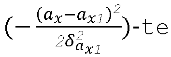 ein viertes Berechnungsuntermodul, das zu Folgendem konfiguriert ist: wenn i gleich k+1 ist, Bestimmen des Zielwahrscheinlichkeitswertes Pi, der dem diskreten Zielwert entspricht, gemäß einer vierten Formel, wobei die vierte Formel folgendermaßen lautet:


x1 ] ist, eine Integralvariable ax ist, ein Integrand

- Fahrwegschätzsystem nach Anspruch 8, wobei, wenn die Zielstatusinformationen ferner eine Quergeschwindigkeit vx1 des sich bewegenden Zielobjektes und eine Längsgeschwindigkeit vy1 des sich bewegenden Zielobjektes umfassen, die Vorhersageeinheit spezifisch zu Folgendem konfiguriert ist: Bestimmen von Koordinaten (x t
0 + nΔt,y t0 +nΔt ) eines in der Zielbewegungsspur enthaltenen Zielspurpunkts gemäß einer fünften Formel, wobei der Zielspurpunkt ein n-ter Spurpunkt in einer Vielzahl von in der Zielbewegungsspur enthaltenen Spurpunkten ist, t0 der aktuelle Zeitpunkt ist, Δt ein vorhergesagter Zeitschritt ist und n eine positive ganze Zahl größer als oder gleich 0 ist;wobei die fünfte Formel
 ay1 die in den Zielstatusinformationen enthaltene Längsbeschleunigung des sich bewegenden Zielobjektes ist, und ax_Abtastung [i] der diskrete Zielwert ist.
 - Fahrwegschätzsystem nach Anspruch 8, wobei das erste Bestimmungsmodul Folgendes umfasst:ein erstes Bestimmungsuntermodul, das dazu konfiguriert ist, eine Dämpfungsverarbeitung an einem Zielwahrscheinlichkeitswert Pi , der dem Zielspurpunkt (x t
0 + nΔt,y t0 +nΔt ) entspricht, gemäß einer sechsten Formel durchzuführen, um nach der Dämpfungsverarbeitung einen Zielwahrscheinlichkeitswert P(x t0 + nΔt,y t0 +nΔt ) zu erlangen, wobei die sechste Formel P(x t0 + nΔt,y t0 +nΔt ) = λn * Pi lautet und λ ein zuvor festgelegter Wert ist; undein zweites Bestimmungsmodul, das dazu konfiguriert ist, zu bestimmen, dass der Zielwahrscheinlichkeitswert, der dem Zielspurpunkt entspricht, der Zielwahrscheinlichkeitswert P(x t0 + nΔt,y t0 +nΔt ) ist, der nach der Dämpfungsverarbeitung erlangt wird. - Fahrwegschätzsystem nach Anspruch 8, wobei das erste Bestimmungsmodul Folgendes umfasst:ein drittes Bestimmungsuntermodul, das zu Folgendem konfiguriert ist: wenn der Zielspurpunkt, der eine erste zuvor festgelegte Bedingung erfüllt, erlangt wird, Erlangen einer Vielzahl von Wahrscheinlichkeitswerten, die dem Zielspurpunkt entsprechen, wobei die erste zuvor festgelegte Bedingung darin besteht, dass sich der Zielspurpunkt in unterschiedlichen Bewegungsspuren befindet; undein viertes Bestimmungsuntermodul, das dazu konfiguriert ist, einen maximalen Wert von Wahrscheinlichkeitswerten, die dem Zielspurpunkt in den unterschiedlichen Bewegungsspuren entsprechen, als den Zielwahrscheinlichkeitswert zu bestimmen, der dem Zielspurpunkt entspricht.
- Fahrwegschätzsystem nach Anspruch 8, wobei das erste Bestimmungsmodul Folgendes umfasst:ein fünftes Bestimmungsuntermodul, das dazu konfiguriert ist, eine historische Bewegungsspur zu erlangen, die für das sich bewegende Zielobjekt zu einem historischen Zeitpunkt vorhergesagt wurde, wobei der historische Zeitpunkt ein Zeitpunkt vor dem aktuellen Zeitpunkt ist;ein sechstes Bestimmungsuntermodul, das zu Folgendem konfiguriert ist: wenn der Zielspurpunkt, der eine zweite zuvor festgelegte Bedingung erfüllt, erlangt wird, Erlangen eines ersten Wahrscheinlichkeitswertes und eines zweiten Wahrscheinlichkeitswertes, die dem Zielspurpunkt entsprechen, wobei die zweite zuvor festgelegte Bedingung darin besteht, dass sich der Zielspurpunkt sowohl in der Zielbewegungsspur als auch in der historischen Bewegungsspur befindet, der erste Wahrscheinlichkeitswert ein Wahrscheinlichkeitswert ist, der dem Zielspurpunkt entspricht und der durch Durchführen einer Vorhersage an dem sich bewegenden Zielobjekt zu dem aktuellen Zeitpunkt erlangt wird, und der zweite Wahrscheinlichkeitswert ein Wahrscheinlichkeitswert ist, der dem Zielspurpunkt entspricht und der durch Durchführen einer Vorhersage an dem sich bewegenden Zielobjekt zu dem historischen Zeitpunkt erlangt wird; undein siebtes Bestimmungsuntermodul, das dazu konfiguriert ist, den größeren von dem ersten Wahrscheinlichkeitswert und dem zweiten Wahrscheinlichkeitswert als den Zielwahrscheinlichkeitswert, der dem Zielspurpunkt entspricht, zu bestimmen.
- Computerlesbares Speichermedium, umfassend eine Anweisung, wobei, wenn die Anweisung auf einem Prozessor ausgeführt wird, der Prozessor in die Lage versetzt wird, das Verfahren nach einem der Ansprüche 1 bis 7 durchzuführen.
Applications Claiming Priority (2)
| Application Number | Priority Date | Filing Date | Title |
|---|---|---|---|
| CN201810458047.0A CN110487288B (zh) | 2018-05-14 | 2018-05-14 | 一种行车道路的估计方法以及行车道路估计系统 |
| PCT/CN2019/084747 WO2019218861A1 (zh) | 2018-05-14 | 2019-04-28 | 一种行车道路的估计方法以及行车道路估计系统 |
Publications (3)
| Publication Number | Publication Date |
|---|---|
| EP3779922A1 EP3779922A1 (de) | 2021-02-17 |
| EP3779922A4 EP3779922A4 (de) | 2021-06-09 |
| EP3779922B1 true EP3779922B1 (de) | 2024-09-11 |
Family
ID=68539401
Family Applications (1)
| Application Number | Title | Priority Date | Filing Date |
|---|---|---|---|
| EP19803310.2A Active EP3779922B1 (de) | 2018-05-14 | 2019-04-28 | Verfahren zur schätzung eines fahrwegs und fahrwegschätzsystem |
Country Status (4)
| Country | Link |
|---|---|
| EP (1) | EP3779922B1 (de) |
| CN (1) | CN110487288B (de) |
| MX (1) | MX2020012153A (de) |
| WO (1) | WO2019218861A1 (de) |
Families Citing this family (22)
| Publication number | Priority date | Publication date | Assignee | Title |
|---|---|---|---|---|
| CN111191697B (zh) * | 2019-12-21 | 2023-04-28 | 武汉光庭信息技术股份有限公司 | 基于传感器融合的adas道路测试验证优化方法和装置 |
| WO2021134742A1 (zh) | 2020-01-02 | 2021-07-08 | 华为技术有限公司 | 一种处理预测运动轨迹的方法、显示约束屏障的方法以及装置 |
| CN113460042B (zh) * | 2020-03-31 | 2022-12-30 | 华为技术有限公司 | 车辆驾驶行为的识别方法以及识别装置 |
| CN115087573B (zh) * | 2020-03-31 | 2023-05-05 | 华为技术有限公司 | 一种关键目标选取方法、装置及系统 |
| CN111583715B (zh) * | 2020-04-29 | 2022-06-03 | 宁波吉利汽车研究开发有限公司 | 一种车辆轨迹预测方法、车辆碰撞预警方法、装置及存储介质 |
| CN113701746B (zh) * | 2020-05-21 | 2025-02-25 | 深圳引望智能技术有限公司 | 目标朝向确定方法和装置 |
| CN114067556B (zh) * | 2020-08-05 | 2023-03-14 | 北京万集科技股份有限公司 | 环境感知方法、装置、服务器和可读存储介质 |
| CN111994085A (zh) * | 2020-08-25 | 2020-11-27 | 吉林大学 | 复杂路况下车辆行驶稳定区域的估计方法 |
| CN111951144B (zh) * | 2020-08-26 | 2022-08-30 | 腾讯科技(深圳)有限公司 | 一种违章路段的确定方法、设备及计算机可读存储介质 |
| CN112596514B (zh) * | 2020-11-18 | 2024-05-31 | 广州文远知行科技有限公司 | 控制操作调整方法、装置、可移动载体及存储介质 |
| CN114945959B (zh) * | 2020-11-23 | 2023-06-20 | 深圳元戎启行科技有限公司 | 行驶轨迹确定方法、装置、计算机设备和存储介质 |
| CN114792148B (zh) * | 2021-01-25 | 2025-09-19 | 魔门塔(苏州)科技有限公司 | 一种运动轨迹的预测方法及装置 |
| CN112884837B (zh) * | 2021-03-16 | 2023-06-20 | 百度在线网络技术(北京)有限公司 | 道路定位方法、装置、设备及存储介质 |
| CN115201804B (zh) * | 2021-04-12 | 2025-08-08 | 武汉智行者科技有限公司 | 目标速度估计方法、装置以及存储介质 |
| CN113963537A (zh) * | 2021-10-19 | 2022-01-21 | 东软睿驰汽车技术(上海)有限公司 | 一种针对路口的车辆轨迹预测方法和相关装置 |
| CN114187578B (zh) * | 2021-12-13 | 2025-09-12 | 北京百度网讯科技有限公司 | 道路连接状态的识别方法及装置、电子设备和介质 |
| WO2023122915A1 (zh) * | 2021-12-27 | 2023-07-06 | 华为技术有限公司 | 一种车辆变道的预警方法及装置 |
| CN114578401B (zh) * | 2022-04-29 | 2022-08-30 | 泽景(西安)汽车电子有限责任公司 | 一种车道航迹点的生成方法、装置、电子设备及存储介质 |
| CN115187637B (zh) * | 2022-09-13 | 2022-11-22 | 北京控制工程研究所 | 目标运动参数实时辨识方法、轨迹预估方法及装置 |
| CN115683116B (zh) * | 2022-11-02 | 2024-11-01 | 联创汽车电子有限公司 | 前车轨迹生成方法及模块 |
| CN117351705A (zh) * | 2023-09-28 | 2024-01-05 | 智慧互通科技股份有限公司 | 一种车道通行能力预测方法及系统 |
| CN118211853B (zh) * | 2024-05-17 | 2024-07-19 | 四川国蓝中天环境科技集团有限公司 | 一种基于跨时空聚类的运渣车活跃点位计算方法 |
Family Cites Families (6)
| Publication number | Priority date | Publication date | Assignee | Title |
|---|---|---|---|---|
| WO2004008648A2 (en) * | 2002-07-15 | 2004-01-22 | Automotive Systems Laboratory, Inc. | Road curvature estimation and automotive target state estimation system |
| JP4062353B1 (ja) * | 2006-11-10 | 2008-03-19 | トヨタ自動車株式会社 | 障害物進路予測方法、装置、およびプログラム |
| EP2352664A4 (de) * | 2008-11-06 | 2014-04-23 | Volvo Technology Corp | Verfahren und system zur bestimmung von strassendaten |
| JP6321532B2 (ja) * | 2014-11-28 | 2018-05-09 | 株式会社デンソー | 車両の走行制御装置 |
| US9784592B2 (en) * | 2015-07-17 | 2017-10-10 | Honda Motor Co., Ltd. | Turn predictions |
| CN105667518B (zh) * | 2016-02-25 | 2018-07-24 | 福州华鹰重工机械有限公司 | 车道检测的方法及装置 |
-
2018
- 2018-05-14 CN CN201810458047.0A patent/CN110487288B/zh active Active
-
2019
- 2019-04-28 MX MX2020012153A patent/MX2020012153A/es unknown
- 2019-04-28 EP EP19803310.2A patent/EP3779922B1/de active Active
- 2019-04-28 WO PCT/CN2019/084747 patent/WO2019218861A1/zh not_active Ceased
Also Published As
| Publication number | Publication date |
|---|---|
| CN110487288A (zh) | 2019-11-22 |
| EP3779922A4 (de) | 2021-06-09 |
| WO2019218861A1 (zh) | 2019-11-21 |
| EP3779922A1 (de) | 2021-02-17 |
| MX2020012153A (es) | 2021-01-29 |
| CN110487288B (zh) | 2024-03-01 |
Similar Documents
| Publication | Publication Date | Title |
|---|---|---|
| EP3779922B1 (de) | Verfahren zur schätzung eines fahrwegs und fahrwegschätzsystem | |
| US11796344B2 (en) | Map information system | |
| CN109927719B (zh) | 一种基于障碍物轨迹预测的辅助驾驶方法和系统 | |
| US7034742B2 (en) | Road curvature estimation and automotive target state estimation system | |
| US10845814B2 (en) | Host vehicle position confidence degree calculation device | |
| EP3715204A1 (de) | Fahrzeugsteuerungsvorrichtung | |
| CN114442101A (zh) | 基于成像毫米波雷达的车辆导航方法、装置、设备及介质 | |
| RU2750243C2 (ru) | Способ и система для формирования траектории для беспилотного автомобиля (sdc) | |
| US20050225477A1 (en) | Road curvature estimation system | |
| CN111583715A (zh) | 一种车辆轨迹预测方法、车辆碰撞预警方法、装置及存储介质 | |
| EP4242998B1 (de) | Verfahren und vorrichtung zur bestimmung von verkehrsstrominformationen, elektronische vorrichtung und speichermedium | |
| KR20200133122A (ko) | 차량 충돌 방지 장치 및 방법 | |
| CN106257242A (zh) | 用于调节道路边界的单元和方法 | |
| RU2751734C2 (ru) | Способы и процессоры для управления рулением беспилотным автомобилем | |
| CN114670851B (zh) | 基于寻优跟踪算法的辅助驾驶系统、方法、终端及介质 | |
| KR101503473B1 (ko) | 차량의 주행 상황 판단 시스템 및 방법 | |
| Chae et al. | Design and vehicle implementation of autonomous lane change algorithm based on probabilistic prediction | |
| US11353595B2 (en) | Sidelobe subtraction method in automotive radar signal processing | |
| CN113227831A (zh) | 基于多传感器数据融合的护栏估计方法和车载设备 | |
| US12485887B2 (en) | Collision aware path planning systems and methods | |
| Li et al. | An overview of factors influencing the mass adoption of self-driving vehicles | |
| CN114148344A (zh) | 一种车辆行为预测方法、装置及车辆 | |
| CN117826797A (zh) | 车队异步避障方法、装置及电子设备 | |
| US20260057233A1 (en) | Training machine learning models to perform vehicle prediction tasks | |
| Cai et al. | Research on optimization of distance ranging method and application of car-following under slope roads |
Legal Events
| Date | Code | Title | Description |
|---|---|---|---|
| STAA | Information on the status of an ep patent application or granted ep patent |
Free format text: STATUS: THE INTERNATIONAL PUBLICATION HAS BEEN MADE |
|
| PUAI | Public reference made under article 153(3) epc to a published international application that has entered the european phase |
Free format text: ORIGINAL CODE: 0009012 |
|
| STAA | Information on the status of an ep patent application or granted ep patent |
Free format text: STATUS: REQUEST FOR EXAMINATION WAS MADE |
|
| 17P | Request for examination filed |
Effective date: 20201027 |
|
| AK | Designated contracting states |
Kind code of ref document: A1 Designated state(s): AL AT BE BG CH CY CZ DE DK EE ES FI FR GB GR HR HU IE IS IT LI LT LU LV MC MK MT NL NO PL PT RO RS SE SI SK SM TR |
|
| AX | Request for extension of the european patent |
Extension state: BA ME |
|
| A4 | Supplementary search report drawn up and despatched |
Effective date: 20210512 |
|
| RIC1 | Information provided on ipc code assigned before grant |
Ipc: G08G 1/16 20060101AFI20210506BHEP Ipc: B60W 40/072 20120101ALI20210506BHEP |
|
| DAV | Request for validation of the european patent (deleted) | ||
| DAX | Request for extension of the european patent (deleted) | ||
| GRAP | Despatch of communication of intention to grant a patent |
Free format text: ORIGINAL CODE: EPIDOSNIGR1 |
|
| STAA | Information on the status of an ep patent application or granted ep patent |
Free format text: STATUS: GRANT OF PATENT IS INTENDED |
|
| INTG | Intention to grant announced |
Effective date: 20240405 |
|
| GRAS | Grant fee paid |
Free format text: ORIGINAL CODE: EPIDOSNIGR3 |
|
| GRAA | (expected) grant |
Free format text: ORIGINAL CODE: 0009210 |
|
| STAA | Information on the status of an ep patent application or granted ep patent |
Free format text: STATUS: THE PATENT HAS BEEN GRANTED |
|
| AK | Designated contracting states |
Kind code of ref document: B1 Designated state(s): AL AT BE BG CH CY CZ DE DK EE ES FI FR GB GR HR HU IE IS IT LI LT LU LV MC MK MT NL NO PL PT RO RS SE SI SK SM TR |
|
| REG | Reference to a national code |
Ref country code: GB Ref legal event code: FG4D |
|
| REG | Reference to a national code |
Ref country code: CH Ref legal event code: EP |
|
| P01 | Opt-out of the competence of the unified patent court (upc) registered |
Free format text: CASE NUMBER: APP_48746/2024 Effective date: 20240827 |
|
| REG | Reference to a national code |
Ref country code: DE Ref legal event code: R096 Ref document number: 602019058782 Country of ref document: DE |
|
| REG | Reference to a national code |
Ref country code: IE Ref legal event code: FG4D |
|
| REG | Reference to a national code |
Ref country code: DE Ref legal event code: R081 Ref document number: 602019058782 Country of ref document: DE Owner name: SHENZHEN YINWANG INTELLIGENT TECHNOLOGIES CO.,, CN Free format text: FORMER OWNER: HUAWEI TECHNOLOGIES CO., LTD., SHENZHEN, GUANGDONG, CN |
|
| RAP2 | Party data changed (patent owner data changed or rights of a patent transferred) |
Owner name: SHENZHEN YINWANG INTELLIGENTTECHNOLOGIES CO., LTD. |
|
| REG | Reference to a national code |
Ref country code: LT Ref legal event code: MG9D |
|
| PG25 | Lapsed in a contracting state [announced via postgrant information from national office to epo] |
Ref country code: NO Free format text: LAPSE BECAUSE OF FAILURE TO SUBMIT A TRANSLATION OF THE DESCRIPTION OR TO PAY THE FEE WITHIN THE PRESCRIBED TIME-LIMIT Effective date: 20241211 |
|
| REG | Reference to a national code |
Ref country code: NL Ref legal event code: MP Effective date: 20240911 |
|
| PG25 | Lapsed in a contracting state [announced via postgrant information from national office to epo] |
Ref country code: GR Free format text: LAPSE BECAUSE OF FAILURE TO SUBMIT A TRANSLATION OF THE DESCRIPTION OR TO PAY THE FEE WITHIN THE PRESCRIBED TIME-LIMIT Effective date: 20241212 Ref country code: FI Free format text: LAPSE BECAUSE OF FAILURE TO SUBMIT A TRANSLATION OF THE DESCRIPTION OR TO PAY THE FEE WITHIN THE PRESCRIBED TIME-LIMIT Effective date: 20240911 |
|
| PG25 | Lapsed in a contracting state [announced via postgrant information from national office to epo] |
Ref country code: BG Free format text: LAPSE BECAUSE OF FAILURE TO SUBMIT A TRANSLATION OF THE DESCRIPTION OR TO PAY THE FEE WITHIN THE PRESCRIBED TIME-LIMIT Effective date: 20240911 |
|
| PG25 | Lapsed in a contracting state [announced via postgrant information from national office to epo] |
Ref country code: LV Free format text: LAPSE BECAUSE OF FAILURE TO SUBMIT A TRANSLATION OF THE DESCRIPTION OR TO PAY THE FEE WITHIN THE PRESCRIBED TIME-LIMIT Effective date: 20240911 |
|
| PG25 | Lapsed in a contracting state [announced via postgrant information from national office to epo] |
Ref country code: HR Free format text: LAPSE BECAUSE OF FAILURE TO SUBMIT A TRANSLATION OF THE DESCRIPTION OR TO PAY THE FEE WITHIN THE PRESCRIBED TIME-LIMIT Effective date: 20240911 |
|
| PG25 | Lapsed in a contracting state [announced via postgrant information from national office to epo] |
Ref country code: RS Free format text: LAPSE BECAUSE OF FAILURE TO SUBMIT A TRANSLATION OF THE DESCRIPTION OR TO PAY THE FEE WITHIN THE PRESCRIBED TIME-LIMIT Effective date: 20241211 Ref country code: ES Free format text: LAPSE BECAUSE OF FAILURE TO SUBMIT A TRANSLATION OF THE DESCRIPTION OR TO PAY THE FEE WITHIN THE PRESCRIBED TIME-LIMIT Effective date: 20240911 |
|
| PG25 | Lapsed in a contracting state [announced via postgrant information from national office to epo] |
Ref country code: RS Free format text: LAPSE BECAUSE OF FAILURE TO SUBMIT A TRANSLATION OF THE DESCRIPTION OR TO PAY THE FEE WITHIN THE PRESCRIBED TIME-LIMIT Effective date: 20241211 Ref country code: NO Free format text: LAPSE BECAUSE OF FAILURE TO SUBMIT A TRANSLATION OF THE DESCRIPTION OR TO PAY THE FEE WITHIN THE PRESCRIBED TIME-LIMIT Effective date: 20241211 Ref country code: LV Free format text: LAPSE BECAUSE OF FAILURE TO SUBMIT A TRANSLATION OF THE DESCRIPTION OR TO PAY THE FEE WITHIN THE PRESCRIBED TIME-LIMIT Effective date: 20240911 Ref country code: HR Free format text: LAPSE BECAUSE OF FAILURE TO SUBMIT A TRANSLATION OF THE DESCRIPTION OR TO PAY THE FEE WITHIN THE PRESCRIBED TIME-LIMIT Effective date: 20240911 Ref country code: GR Free format text: LAPSE BECAUSE OF FAILURE TO SUBMIT A TRANSLATION OF THE DESCRIPTION OR TO PAY THE FEE WITHIN THE PRESCRIBED TIME-LIMIT Effective date: 20241212 Ref country code: FI Free format text: LAPSE BECAUSE OF FAILURE TO SUBMIT A TRANSLATION OF THE DESCRIPTION OR TO PAY THE FEE WITHIN THE PRESCRIBED TIME-LIMIT Effective date: 20240911 Ref country code: ES Free format text: LAPSE BECAUSE OF FAILURE TO SUBMIT A TRANSLATION OF THE DESCRIPTION OR TO PAY THE FEE WITHIN THE PRESCRIBED TIME-LIMIT Effective date: 20240911 Ref country code: BG Free format text: LAPSE BECAUSE OF FAILURE TO SUBMIT A TRANSLATION OF THE DESCRIPTION OR TO PAY THE FEE WITHIN THE PRESCRIBED TIME-LIMIT Effective date: 20240911 |
|
| REG | Reference to a national code |
Ref country code: AT Ref legal event code: MK05 Ref document number: 1723406 Country of ref document: AT Kind code of ref document: T Effective date: 20240911 |
|
| PG25 | Lapsed in a contracting state [announced via postgrant information from national office to epo] |
Ref country code: NL Free format text: LAPSE BECAUSE OF FAILURE TO SUBMIT A TRANSLATION OF THE DESCRIPTION OR TO PAY THE FEE WITHIN THE PRESCRIBED TIME-LIMIT Effective date: 20240911 |
|
| PG25 | Lapsed in a contracting state [announced via postgrant information from national office to epo] |
Ref country code: PT Free format text: LAPSE BECAUSE OF FAILURE TO SUBMIT A TRANSLATION OF THE DESCRIPTION OR TO PAY THE FEE WITHIN THE PRESCRIBED TIME-LIMIT Effective date: 20250113 Ref country code: IS Free format text: LAPSE BECAUSE OF FAILURE TO SUBMIT A TRANSLATION OF THE DESCRIPTION OR TO PAY THE FEE WITHIN THE PRESCRIBED TIME-LIMIT Effective date: 20250111 |
|
| PG25 | Lapsed in a contracting state [announced via postgrant information from national office to epo] |
Ref country code: SM Free format text: LAPSE BECAUSE OF FAILURE TO SUBMIT A TRANSLATION OF THE DESCRIPTION OR TO PAY THE FEE WITHIN THE PRESCRIBED TIME-LIMIT Effective date: 20240911 Ref country code: RO Free format text: LAPSE BECAUSE OF FAILURE TO SUBMIT A TRANSLATION OF THE DESCRIPTION OR TO PAY THE FEE WITHIN THE PRESCRIBED TIME-LIMIT Effective date: 20240911 |
|
| PG25 | Lapsed in a contracting state [announced via postgrant information from national office to epo] |
Ref country code: AT Free format text: LAPSE BECAUSE OF FAILURE TO SUBMIT A TRANSLATION OF THE DESCRIPTION OR TO PAY THE FEE WITHIN THE PRESCRIBED TIME-LIMIT Effective date: 20240911 Ref country code: EE Free format text: LAPSE BECAUSE OF FAILURE TO SUBMIT A TRANSLATION OF THE DESCRIPTION OR TO PAY THE FEE WITHIN THE PRESCRIBED TIME-LIMIT Effective date: 20240911 |
|
| PG25 | Lapsed in a contracting state [announced via postgrant information from national office to epo] |
Ref country code: CZ Free format text: LAPSE BECAUSE OF FAILURE TO SUBMIT A TRANSLATION OF THE DESCRIPTION OR TO PAY THE FEE WITHIN THE PRESCRIBED TIME-LIMIT Effective date: 20240911 Ref country code: PL Free format text: LAPSE BECAUSE OF FAILURE TO SUBMIT A TRANSLATION OF THE DESCRIPTION OR TO PAY THE FEE WITHIN THE PRESCRIBED TIME-LIMIT Effective date: 20240911 |
|
| PG25 | Lapsed in a contracting state [announced via postgrant information from national office to epo] |
Ref country code: IT Free format text: LAPSE BECAUSE OF FAILURE TO SUBMIT A TRANSLATION OF THE DESCRIPTION OR TO PAY THE FEE WITHIN THE PRESCRIBED TIME-LIMIT Effective date: 20240911 Ref country code: SK Free format text: LAPSE BECAUSE OF FAILURE TO SUBMIT A TRANSLATION OF THE DESCRIPTION OR TO PAY THE FEE WITHIN THE PRESCRIBED TIME-LIMIT Effective date: 20240911 |
|
| REG | Reference to a national code |
Ref country code: DE Ref legal event code: R097 Ref document number: 602019058782 Country of ref document: DE |
|
| PGFP | Annual fee paid to national office [announced via postgrant information from national office to epo] |
Ref country code: DE Payment date: 20250305 Year of fee payment: 7 |
|
| PG25 | Lapsed in a contracting state [announced via postgrant information from national office to epo] |
Ref country code: DK Free format text: LAPSE BECAUSE OF FAILURE TO SUBMIT A TRANSLATION OF THE DESCRIPTION OR TO PAY THE FEE WITHIN THE PRESCRIBED TIME-LIMIT Effective date: 20240911 |
|
| PLBE | No opposition filed within time limit |
Free format text: ORIGINAL CODE: 0009261 |
|
| STAA | Information on the status of an ep patent application or granted ep patent |
Free format text: STATUS: NO OPPOSITION FILED WITHIN TIME LIMIT |
|
| 26N | No opposition filed |
Effective date: 20250612 |
|
| PG25 | Lapsed in a contracting state [announced via postgrant information from national office to epo] |
Ref country code: SE Free format text: LAPSE BECAUSE OF FAILURE TO SUBMIT A TRANSLATION OF THE DESCRIPTION OR TO PAY THE FEE WITHIN THE PRESCRIBED TIME-LIMIT Effective date: 20240911 |
|
| REG | Reference to a national code |
Ref country code: CH Ref legal event code: H13 Free format text: ST27 STATUS EVENT CODE: U-0-0-H10-H13 (AS PROVIDED BY THE NATIONAL OFFICE) Effective date: 20251125 |
|
| PG25 | Lapsed in a contracting state [announced via postgrant information from national office to epo] |
Ref country code: LU Free format text: LAPSE BECAUSE OF NON-PAYMENT OF DUE FEES Effective date: 20250428 |
|
| PG25 | Lapsed in a contracting state [announced via postgrant information from national office to epo] |
Ref country code: MC Free format text: LAPSE BECAUSE OF FAILURE TO SUBMIT A TRANSLATION OF THE DESCRIPTION OR TO PAY THE FEE WITHIN THE PRESCRIBED TIME-LIMIT Effective date: 20240911 |
|
| GBPC | Gb: european patent ceased through non-payment of renewal fee |
Effective date: 20250428 |
|
| REG | Reference to a national code |
Ref country code: BE Ref legal event code: MM Effective date: 20250430 |
|
| PG25 | Lapsed in a contracting state [announced via postgrant information from national office to epo] |
Ref country code: GB Free format text: LAPSE BECAUSE OF NON-PAYMENT OF DUE FEES Effective date: 20250428 |
|
| PG25 | Lapsed in a contracting state [announced via postgrant information from national office to epo] |
Ref country code: FR Free format text: LAPSE BECAUSE OF NON-PAYMENT OF DUE FEES Effective date: 20250430 |
|
| PG25 | Lapsed in a contracting state [announced via postgrant information from national office to epo] |
Ref country code: BE Free format text: LAPSE BECAUSE OF NON-PAYMENT OF DUE FEES Effective date: 20250430 |
|
| PG25 | Lapsed in a contracting state [announced via postgrant information from national office to epo] |
Ref country code: CH Free format text: LAPSE BECAUSE OF NON-PAYMENT OF DUE FEES Effective date: 20250430 |
|
| PG25 | Lapsed in a contracting state [announced via postgrant information from national office to epo] |
Ref country code: IE Free format text: LAPSE BECAUSE OF NON-PAYMENT OF DUE FEES Effective date: 20250428 |