EP3778364B1 - Verschlussvorrichtung zum verbinden eines behälters z.b. an einem fahrrad - Google Patents
Verschlussvorrichtung zum verbinden eines behälters z.b. an einem fahrrad Download PDFInfo
- Publication number
- EP3778364B1 EP3778364B1 EP20196134.9A EP20196134A EP3778364B1 EP 3778364 B1 EP3778364 B1 EP 3778364B1 EP 20196134 A EP20196134 A EP 20196134A EP 3778364 B1 EP3778364 B1 EP 3778364B1
- Authority
- EP
- European Patent Office
- Prior art keywords
- closure
- container
- closure part
- closing direction
- closure device
- Prior art date
- Legal status (The legal status is an assumption and is not a legal conclusion. Google has not performed a legal analysis and makes no representation as to the accuracy of the status listed.)
- Active
Links
Images


Classifications
-
- F—MECHANICAL ENGINEERING; LIGHTING; HEATING; WEAPONS; BLASTING
- F16—ENGINEERING ELEMENTS AND UNITS; GENERAL MEASURES FOR PRODUCING AND MAINTAINING EFFECTIVE FUNCTIONING OF MACHINES OR INSTALLATIONS; THERMAL INSULATION IN GENERAL
- F16M—FRAMES, CASINGS OR BEDS OF ENGINES, MACHINES OR APPARATUS, NOT SPECIFIC TO ENGINES, MACHINES OR APPARATUS PROVIDED FOR ELSEWHERE; STANDS; SUPPORTS
- F16M13/00—Other supports for positioning apparatus or articles; Means for steadying hand-held apparatus or articles
- F16M13/02—Other supports for positioning apparatus or articles; Means for steadying hand-held apparatus or articles for supporting on, or attaching to, an object, e.g. tree, gate, window-frame, cycle
-
- B—PERFORMING OPERATIONS; TRANSPORTING
- B62—LAND VEHICLES FOR TRAVELLING OTHERWISE THAN ON RAILS
- B62J—CYCLE SADDLES OR SEATS; AUXILIARY DEVICES OR ACCESSORIES SPECIALLY ADAPTED TO CYCLES AND NOT OTHERWISE PROVIDED FOR, e.g. ARTICLE CARRIERS OR CYCLE PROTECTORS
- B62J11/00—Supporting arrangements specially adapted for fastening specific devices to cycles, e.g. supports for attaching maps
- B62J11/04—Supporting arrangements specially adapted for fastening specific devices to cycles, e.g. supports for attaching maps for bottles
-
- F—MECHANICAL ENGINEERING; LIGHTING; HEATING; WEAPONS; BLASTING
- F16—ENGINEERING ELEMENTS AND UNITS; GENERAL MEASURES FOR PRODUCING AND MAINTAINING EFFECTIVE FUNCTIONING OF MACHINES OR INSTALLATIONS; THERMAL INSULATION IN GENERAL
- F16B—DEVICES FOR FASTENING OR SECURING CONSTRUCTIONAL ELEMENTS OR MACHINE PARTS TOGETHER, e.g. NAILS, BOLTS, CIRCLIPS, CLAMPS, CLIPS OR WEDGES; JOINTS OR JOINTING
- F16B1/00—Devices for securing together, or preventing relative movement between, constructional elements or machine parts
-
- F—MECHANICAL ENGINEERING; LIGHTING; HEATING; WEAPONS; BLASTING
- F16—ENGINEERING ELEMENTS AND UNITS; GENERAL MEASURES FOR PRODUCING AND MAINTAINING EFFECTIVE FUNCTIONING OF MACHINES OR INSTALLATIONS; THERMAL INSULATION IN GENERAL
- F16M—FRAMES, CASINGS OR BEDS OF ENGINES, MACHINES OR APPARATUS, NOT SPECIFIC TO ENGINES, MACHINES OR APPARATUS PROVIDED FOR ELSEWHERE; STANDS; SUPPORTS
- F16M11/00—Stands or trestles as supports for apparatus or articles placed thereon ; Stands for scientific apparatus such as gravitational force meters
- F16M11/02—Heads
- F16M11/04—Means for attachment of apparatus; Means allowing adjustment of the apparatus relatively to the stand
- F16M11/041—Allowing quick release of the apparatus
-
- F—MECHANICAL ENGINEERING; LIGHTING; HEATING; WEAPONS; BLASTING
- F16—ENGINEERING ELEMENTS AND UNITS; GENERAL MEASURES FOR PRODUCING AND MAINTAINING EFFECTIVE FUNCTIONING OF MACHINES OR INSTALLATIONS; THERMAL INSULATION IN GENERAL
- F16B—DEVICES FOR FASTENING OR SECURING CONSTRUCTIONAL ELEMENTS OR MACHINE PARTS TOGETHER, e.g. NAILS, BOLTS, CIRCLIPS, CLAMPS, CLIPS OR WEDGES; JOINTS OR JOINTING
- F16B2200/00—Constructional details of connections not covered for in other groups of this subclass
- F16B2200/83—Use of a magnetic material
-
- H—ELECTRICITY
- H01—ELECTRIC ELEMENTS
- H01F—MAGNETS; INDUCTANCES; TRANSFORMERS; SELECTION OF MATERIALS FOR THEIR MAGNETIC PROPERTIES
- H01F7/00—Magnets
- H01F7/02—Permanent magnets [PM]
- H01F7/0231—Magnetic circuits with PM for power or force generation
- H01F7/0252—PM holding devices
- H01F7/0263—Closures, bags, bands, engagement devices with male and female parts
Definitions
- the invention relates to a locking device for connecting a container to a frame of a vehicle, in particular a bicycle or tricycle.
- Such a closure device comprises a first closure part, which is to be arranged on the frame and has a first magnetic element, and a second closure part, which is assigned to the container and has a second magnetic element, wherein the second closure part can be attached to the first closure part in a closing direction and in a closed position is mechanically latched to the first closure part.
- Such a closure device can be used, for example, to attach a container in the form of a drinking bottle to the frame of a bicycle.
- a clamping bracket is attached to a frame and has magnetic elements that interact with a magnetically active ring of the drinking bottle to attach a drinking bottle to the frame.
- connection It is also known to fasten containers in the form of drinking bottles to a frame of a vehicle in a latching manner, in which connection it has also been considered to use magnetic elements to secure the connection.
- a locking device with which a container for example a drinking bottle
- a container for example a drinking bottle
- the container should be able to be accommodated on the vehicle in a space-saving manner, with only limited space being available in a frame opening of a bicycle frame, for example.
- the closure device In the open position, the closure device should have a small installation space both on the vehicle and on the container, so that the closure parts of the closure device do not interfere. It is also desirable to design the closure device in a cost-effective manner, with particular consideration being given to the fact that Containers, for example in the form of drinking bottles, have to be replaced after a limited period of use.
- a fastening device for a bicycle bottle on a bicycle in which a closure part to which a bicycle bottle can be attached is attached to a bicycle frame.
- the bicycle bottle has a magnet, via which the bicycle bottle is held in the attached position on the closure part.
- the object of the present invention is to provide a closure device that is easy to handle, enables a container to be reliably fastened to the frame of a vehicle and can also be used in a variety of ways.
- the second closure part can be releasably connected to the container.
- the present closure device can be used in a modular manner together with very different containers. Since the second closure part can be detachably connected to the container, the closure device can be used to connect different containers to the frame of a vehicle, in particular to the frame of a bicycle. In particular, the detachable connection of the second closure part to the container makes it possible to exchange the container and replace it with another container, which can be of the same type or of a completely different type.
- the second closure part can in particular be connectable to an adapter part of the container in a form-fitting manner. To release the connection of the second closure part with the container, the positive connection can be canceled so that the second closure part the adapter part and thus can be separated from the container.
- the adapter part is in this case firmly connected to the container, for example welded to the container or fixed to the container in some other way, or also integrated into the container in one piece.
- the second closure part has a body and an adjustable (in particular rotatable) fastening element arranged on the body.
- the fastening element serves to connect the second closure part to the container in a first position--when the second closure part is attached to the container.
- the fastening element can be moved out of this first position in order to release the connection between the container and the second closure part, so that by adjusting the fastening element, in particular by twisting the fastening element, the second closure part can be easily separated from the container in order to to connect the second closure part, for example, to another container.
- Containers for example in the form of drinking bottles, are generally available at low cost and have to be replaced regularly after prolonged use. Because the second closure part is detachably connected to the container, replacing the container does not mean that the closure device also has to be replaced. Rather, the closure device can continue to be used by connecting the second closure part to another container.
- the fastening element can easily be adjusted by hand or using a simple tool, for example a screwdriver or a coin or the like.
- the fastener may have a slot that can be engaged with a coin to twist the fastener.
- the fastening element can have a locking web, for example, which can be positively engaged with at least one locking element on the side of the adapter part of the container by adjusting, in particular twisting.
- the closure parts of the closure device can be attached to one another in the closing direction in order to close the closure device and to connect the closure parts to one another.
- the closing of the closure device is supported magnetically by the magnetic elements of the closure parts, so that when the closure parts are placed against one another, the closure parts are magnetically drawn towards one another and thus reach their closed position.
- closure parts In the closed position, the closure parts are mechanically latched to one another, so that the closure parts are held together in a load-bearing and form-fitting manner.
- one of the closure parts has a locking piece and the other of the closure parts has a locking element, which engage in one another in the closed position such that the second closure part is fixed to the first closure part counter to the closing direction.
- the blocking piece can be designed, for example, as a protruding locking pin
- the locking element can be designed, for example, as an elastically resilient component transverse to the closing direction.
- a latching projection of the locking piece can thus run up against a latching projection of the locking element and in this way push the locking element aside in an elastically resilient manner until the locking piece snaps positively into engagement with the locking element.
- the latching projections of the blocking piece and the locking element are then in engagement with one another, so that the closure parts are held together in a form-fitting manner.
- the locking element can be ring-shaped, for example, with the locking element being opened, for example, at a peripheral location by an opening through which the locking piece can be moved to open the closure device.
- the locking element thus implements a C-ring, which in the closed position at least partially encompasses the blocking piece and thereby holds it in a form-fitting manner.
- the locking piece can be moved through the opening formed at a peripheral location of the locking member, so that the locking piece can be disengaged from the locking member and thereby released from the locking member.
- the closure device can be opened in order to release the closure parts from one another by moving the second closure part towards the first closure part in an opening direction that differs from the closing direction.
- the latching between the closure parts can be canceled by the movement in the opening direction, so that the closure parts can be released from one another and the container assigned to the second closure part can thus be removed from the frame of the vehicle.
- the fact that the opening direction differs from the closing direction is to be understood here as meaning that the opening direction is in a different direction than that Closing direction has and in particular is not directed against the closing direction.
- the opening direction can, for example, lie in a plane extending transversely to the closing direction and can be realized, for example, by a direction of rotation directed around the closing direction.
- the closure device can thus be closed in that the closure parts are attached to one another in the closing direction.
- the closure device is then opened by the closure parts being rotated relative to one another about the closing direction in order in this way to cancel the latching between the closure parts.
- one of the closure parts can, for example, have a pivot pin which, in the closed position, engages in a rotary opening of the other closure part and supports the closure parts rotatably on one another along the opening direction (directed around the closing direction).
- the closure parts can thus be rotated relative to one another about the pivot pin, so that the opening movement is guided.
- canting of the closure parts relative to each other when opening can be avoided in this way.
- the pivot pin can be formed, for example, on the first closure part and protrude from a body of the first closure part along the closing direction.
- the rotary opening can be formed, for example, on the second closure part, for example in the fastening element arranged on the second closure part, via which the second closure part is detachably connected to the container.
- the first closure part and the second closure part each have two magnetic elements, which are formed by permanent magnets.
- the magnetic elements of each closure part are spaced apart from one another transversely to the closing direction, the magnetic elements of the first closure part interacting magnetically with the magnetic elements of the second closure part when closing and thus magnetically supporting the closing of the closure device.
- closure parts are thus automatically drawn towards one another when they are attached, so that the closing of the closure device, in an advantageous embodiment, can take place at least largely automatically.
- the magnetic elements of each closure part point with opposite magnetic poles towards the respective other closure part.
- the two magnetic elements of the first closure part thus point towards the second closure part with different magnetic poles, namely a north pole and a south pole.
- the magnetic elements of the second closure part with opposite magnetic poles namely a south pole and a north pole, point towards the first closure part.
- a container for use on a bicycle can be designed, for example, as a bottle, bag or other container.
- the container can, for example, be a drinking bottle, a tool container or a container for a battery.
- the container can in particular be designed as a rigid structure (with a rigid body) or as a flexible fabric (for example as a bag with a flexibly deformable body).
- the locking device of the type described above can be used in particular on a bicycle, in which case such a bicycle can be driven by human pedal power or else electrically.
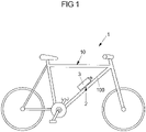
- FIG. 1 1 shows a schematic view of a vehicle 1 in the form of a bicycle, which has a frame 10 with a frame rod 100 to which a container 3, for example in the form of a water bottle or another container, for example a bag, is attached via a closure device 2.
- a container 3 for example in the form of a water bottle or another container, for example a bag
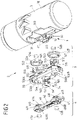
- FIGS 2 to 6A , 6B show an embodiment of a closure device 2, which is used to connect a container 3 to the frame 10 of a vehicle 1.
- the closure device 2 has a first closure part 4 which is to be firmly connected to a frame rod 100 of the frame 10 of the vehicle 1, for example to be screwed.
- a second closure part 5 can be attached to the first closure part 4, which is to be firmly connected to the container 3 (but is detachable, as will be explained below).
- the first closure part 4 has a body 40 from which two locking pieces 41A, 41B project.
- the locking pieces 41A, 41B each have a shank 411, at the end of which is remote from the body 40 a latching projection 410 is formed which runs around the shank 411 and projects radially from the shank 411 to the outside.
- the body 40 On the side facing away from the locking pieces 41A, 41B, the body 40 has receiving openings 400A, 400B at the location of the locking pieces 41A, 41B, into which magnetic elements 43A, 43B are inserted and firmly connected to the body 40.
- the second closure part 5 has a body 50 in which two closure openings 500A, 500B are formed, in each of which a locking element 51A, 51B is accommodated via a fastening plate 52A, 52B.
- the locking elements 51A, 51B are accommodated and fastened in fastening grooves 520 of the fastening plates 52A, 52B and enclose magnet receptacles 521 which are designed as raised sections and in which a magnet element 53A, 53B is arranged in each case.
- the locking elements 51A, 51B are ring-shaped, but open circumferentially via an opening 511 each, so that the locking elements 51A, 51B represent C-rings.
- Each locking element 51A, 51B is fixed to the associated fastening plate 52A, 52B in such a way that the locking element 51A, 51B is elastically resilient and, in particular, can be spread radially to prevent the locking pieces 41A, 41B of the first closure part 4 from engaging in the locking elements 51A, 51B of the second closure part 5 to allow.
- Each locking element 51A, 51B has an inner peripheral locking projection 510 (possibly interrupted in sections), which projects radially inward from an annular body 512 of the locking element 51A, 51B.
- the latching projections 510 of the locking elements 51A, 51B are in latching engagement with the latching projections 410 of the locking pieces 41A, 41B of the first closure part 4, so that the closure parts 4, 5 are held together in a form-fitting manner.
- the locking elements 51A, 51B In the mounted position, the locking elements 51A, 51B, held by the fastening plates 52A, 52B, lie in the closure openings 500A, 500B of the body 50 of the second closure part 5.
- the second closure part 5 can be moved in a closing direction X, as shown in FIG 4 shown, are attached to the first closure part 4, as a result of which the locking pieces 41A, 41B of the first closure part 4 dip into the closure openings 500A, 500B and thus into the locking elements 51A, 51B of the second closure part 5, and in the process the locking elements 51A, 51B are engaged by the latching projections 410, 510 expand towards one another until the locking pieces 41A, 41B snap into positive engagement with the locking elements 51A, 51B and the second closure part 5 is thereby fixed to the first closure part 4.
- the closing process is magnetically assisted by the magnetic elements 43A, 43B, 53A, 53B, which are magnetically attracted to one another, so that the closure device 2 can be closed largely automatically by approaching the second closure part 5 to the first closure part 4 .
- the closure device 2 While the closure device 2 is closed by applying the second closure part 5 to the first closure part 4 in the closing direction X, the closure device 2 can be rotated about the closing direction X by rotating the second closure part 5 connected to the container 3 relative to the first closure part 4 opening direction Y ( 4 ) to be reopened.
- Locking pieces 41A, 41B are moved through the openings 511 of the locking elements 51A, 51B and pass out of the area of the locking openings 500A, 500B through the locking openings 500A, 500B laterally opening side openings 502A, 502B.
- the form-fitting engagement between the closure parts 4, 5 is thus eliminated, so that the second closure part 5 can be removed from the first closure part 4.
- a pivot pin 42 protruding from the body 40 of the first closure part 4 engages a rotary opening 542 on a fastening element 54 on the body 50 of the second closure part 5, via which the second closure part 5 is rotatably mounted on the first closure part 4 in the opening direction Y.
- the opening movement of the second closure part 5 is guided relative to the first closure part 4, which simplifies handling and in particular prevents the closure parts 4, 5 from tilting when opening.
- the magnetic elements 43A, 43B, 53A, 53B of each closure part 4, 5 have different poles N, S to the respective other closure part 5, 4.
- the magnetic elements 43A, 43B of the first closure part 4 have a north pole N ( Magnetic element 43A) and on the other hand with a south pole S (magnetic element 43B) towards the second closure part 5.
- the magnetic elements 53A, 53B of the second closure part 5 point on the one hand with a south pole S (magnetic element 43A) and on the other hand with a north pole N (magnetic element 53B) towards the first closure part 4.
- This opposite polarization means that the closure parts 4, 5 can only be attached to one another in exactly one position, which ensures that the closure device is closed when the locking pieces 41A, 41B are fully engaged with the locking elements 51A, 51B can be done reliably.
- the magnetic elements 53A, 53B of the second closure part 5 are also moved relative to the magnetic elements 43A, 43B of the first closure part 4, so that the magnetic attraction between the magnetic elements 43A, 43B, 53A, 53B is weakened and the closure parts 4, 5 can thus be easily removed from each other.
- the second closure part 5 is fixed to the container 3, for example a drinking bottle, so that the second closure part 5 can be used to fasten the container 3 to the first closure part 4 and thus to the frame 10 of the vehicle 1.
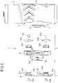
- the connection of the second closure part 5 to the container 3 can be released here (when the closure device 2 is open) by connecting the second closure part 5 with its body 50 in a receiving recess 31 is inserted on a body 30 of the container 3 and connected to an adapter part 6 of the container 3 via the fastening element 54 .
- the fastener 54 is rotatably received in an opening 501 of the body 50 of the second closure part 5 .
- the fastening element 54 has a head 540 from which a shank 543 with a locking web 544 arranged thereon protrudes.
- a tool engagement in the form of a slot 541 is formed in the head 540 so that the fastening element 54 can be twisted, for example by using a coin in the opening 501 of the body 50 of the second closure part 5 .
- the adapter part 6 is firmly connected to the body 30 of the container 3 .
- the adapter part 6 is received via a plate element 60 on a fastening surface 310 in the receiving recess 31 and, for example, is welded or glued to the body 30 .
- Projecting from the plate member 60 are locking members 61 spaced apart by an engagement slot 62 and each having a recess 610 formed therein.
- the fastening element 54 is inserted into the Figures 6A, 6B shown position to the body 50 of the second closure part 5, so that the locking web 544 on the shaft 543 of the fastening element 54 can dip into the engagement slot 62 between the locking elements 61 of the adapter part 6 when the second closure part 5 is inserted into the receiving recess 31.
- the fastening element 54 comes into contact with a section of the adapter part 6 via a pivot point 545, as shown in FIG Figure 6B is evident.
- the fastener 54 By twisting the fastener 54 (e.g. using a coin that engages in the slot 541 on the head 540 of the fastener 50), the fastener 54 is then twisted in the opening 501 of the body 50 of the second closure part 5, so that the locking bar 544 positively engages passes with the recesses 610 within the locking elements 61 of the adapter part 6, as this Figures 5A and 5B is evident.
- the second closure part 5 is thus firmly but detachably fixed to the adapter part 6 of the container 3 .
- the container 3 is also fixed to the frame 10 via this.
- the container 3 can be designed as a drinking bottle, as a storage container for tools or other objects, e.g. for a battery. However, the container 3 can also be implemented as a bag or the like.
- the closure device 2 can be used to connect a container 3 to a frame 10 of a vehicle 1, in particular a bicycle or a tricycle, wherein the vehicle 1 can be powered by human power or else electrically. Because the second closure part 5 is detachably fixed to the container 3, the container 3 can be exchanged, which enables the use of a closure device 2 with very different containers 3. Thus, if the container 3 is to be replaced by another container, the second closure part 5 can easily be detached from the previous container 3 in order to connect the second closure part 5 to another container and thus use the closure device 2 again.
- the container 3 can be closed by directly attaching the closure parts 4, 5 to one another and can be opened again by rotating the container 3, comparatively little space is required on the vehicle 1 for handling the container 3 (compared to to known containers, for example in the form of drinking bottles, which are to be moved tangentially along the frame rod 100 for attachment or detachment).
- the closure device 2 also reliably holds the container 3 on the frame 10 and is in particular also insensitive to mechanical shocks when the vehicle 1 is in use.
Landscapes
- Engineering & Computer Science (AREA)
- General Engineering & Computer Science (AREA)
- Mechanical Engineering (AREA)
- Passenger Equipment (AREA)
- Closures For Containers (AREA)
- Fittings On The Vehicle Exterior For Carrying Loads, And Devices For Holding Or Mounting Articles (AREA)
- Auxiliary Devices For And Details Of Packaging Control (AREA)
- Motorcycle And Bicycle Frame (AREA)
- Automatic Cycles, And Cycles In General (AREA)
- Cooling, Air Intake And Gas Exhaust, And Fuel Tank Arrangements In Propulsion Units (AREA)
- Lock And Its Accessories (AREA)
- Vehicle Step Arrangements And Article Storage (AREA)
Applications Claiming Priority (3)
| Application Number | Priority Date | Filing Date | Title |
|---|---|---|---|
| DE102016216422.8A DE102016216422A1 (de) | 2016-08-31 | 2016-08-31 | Verschlussvorrichtung zum Verbinden eines Behälters z.B. an einem Fahrrad |
| EP17765357.3A EP3507176B1 (de) | 2016-08-31 | 2017-08-24 | Verschlussvorrichtung zum verbinden eines behälters z.b. an einem fahrrad |
| PCT/EP2017/071349 WO2018041716A1 (de) | 2016-08-31 | 2017-08-24 | Verschlussvorrichtung zum verbinden eines behälters z.b. an einem fahrrad |
Related Parent Applications (2)
| Application Number | Title | Priority Date | Filing Date |
|---|---|---|---|
| EP17765357.3A Division EP3507176B1 (de) | 2016-08-31 | 2017-08-24 | Verschlussvorrichtung zum verbinden eines behälters z.b. an einem fahrrad |
| EP17765357.3A Division-Into EP3507176B1 (de) | 2016-08-31 | 2017-08-24 | Verschlussvorrichtung zum verbinden eines behälters z.b. an einem fahrrad |
Publications (2)
| Publication Number | Publication Date |
|---|---|
| EP3778364A1 EP3778364A1 (de) | 2021-02-17 |
| EP3778364B1 true EP3778364B1 (de) | 2022-11-23 |
Family
ID=59858679
Family Applications (2)
| Application Number | Title | Priority Date | Filing Date |
|---|---|---|---|
| EP20196134.9A Active EP3778364B1 (de) | 2016-08-31 | 2017-08-24 | Verschlussvorrichtung zum verbinden eines behälters z.b. an einem fahrrad |
| EP17765357.3A Active EP3507176B1 (de) | 2016-08-31 | 2017-08-24 | Verschlussvorrichtung zum verbinden eines behälters z.b. an einem fahrrad |
Family Applications After (1)
| Application Number | Title | Priority Date | Filing Date |
|---|---|---|---|
| EP17765357.3A Active EP3507176B1 (de) | 2016-08-31 | 2017-08-24 | Verschlussvorrichtung zum verbinden eines behälters z.b. an einem fahrrad |
Country Status (13)
| Country | Link |
|---|---|
| US (1) | US10703429B2 (enExample) |
| EP (2) | EP3778364B1 (enExample) |
| JP (1) | JP6920438B2 (enExample) |
| KR (1) | KR102370398B1 (enExample) |
| CN (2) | CN113371108B (enExample) |
| BR (1) | BR112019003571B1 (enExample) |
| CA (1) | CA3036615A1 (enExample) |
| DE (1) | DE102016216422A1 (enExample) |
| DK (2) | DK3507176T3 (enExample) |
| ES (2) | ES2936335T3 (enExample) |
| PL (2) | PL3507176T3 (enExample) |
| PT (2) | PT3778364T (enExample) |
| WO (1) | WO2018041716A1 (enExample) |
Families Citing this family (22)
| Publication number | Priority date | Publication date | Assignee | Title |
|---|---|---|---|---|
| BR112017000968A2 (pt) * | 2014-07-18 | 2018-01-16 | Ferno-Washington, Inc. | mecanismo de fixação de bolsa magnética, método para utilizar um conjunto de bolsas, e, kit de adaptação de bolsa. |
| DE102016216422A1 (de) * | 2016-08-31 | 2018-03-01 | Fidlock Gmbh | Verschlussvorrichtung zum Verbinden eines Behälters z.B. an einem Fahrrad |
| DE102017201917B4 (de) | 2017-02-07 | 2022-12-15 | Fidlock Gmbh | Verschlusssystem zum Verbinden einer ersten Baugruppe mit einer zweiten Baugruppe |
| US10874178B2 (en) | 2017-12-07 | 2020-12-29 | Wonderland Switzerland Ag | Magnetic buckling assembly |
| CN209573440U (zh) | 2018-09-20 | 2019-11-05 | 明门(中国)幼童用品有限公司 | 预防意外释锁的扣具 |
| DE102019206054A1 (de) * | 2019-04-26 | 2020-10-29 | Fidlock Gmbh | Verschlussvorrichtung zum Verbinden von zwei Baugruppen miteinander |
| CN112237315B (zh) | 2019-07-17 | 2023-09-29 | 明门瑞士股份有限公司 | 扣具 |
| CN117016924A (zh) | 2019-07-17 | 2023-11-10 | 明门瑞士股份有限公司 | 扣具 |
| DE102019215277A1 (de) * | 2019-10-02 | 2021-04-08 | Fidlock Gmbh | Verschlussvorrichtung mit aneinander ansetzbaren Verschlussteilen |
| IT202000001495U1 (it) | 2020-04-07 | 2021-10-07 | Texa Spa | Sistema di ancoraggio per sensori di allineamento di un veicolo rispetto ad un pannello per la calibrazione dei componenti adas |
| US11897567B2 (en) * | 2020-05-28 | 2024-02-13 | Sram, Llc | Mounting interfaces, devices therewith, accessories therefor, and methods of manufacture and use thereof |
| US12287175B2 (en) * | 2020-08-21 | 2025-04-29 | Magne-Tech, Llc | Accessory mounts |
| NL2029080B1 (en) * | 2021-08-30 | 2023-03-15 | Invented Here B V | Mounting device for a bicycle accessory, mounting system, and method of mounting |
| US11952066B2 (en) * | 2021-09-15 | 2024-04-09 | Trevor Ycas | Magnetic bottle holder |
| WO2023081116A1 (en) | 2021-11-02 | 2023-05-11 | Oakley, Inc. | Adjustable shield for helmet |
| US11878758B2 (en) * | 2022-01-03 | 2024-01-23 | Yuan-Hung WEN | Bottle holder |
| US11878759B2 (en) * | 2022-01-31 | 2024-01-23 | Ara Ohanian | Aerodynamic water bottle |
| IT202200002825A1 (it) * | 2022-02-16 | 2023-08-16 | Wen Yuan Hung | "portaborraccia" |
| DE102022104735B3 (de) * | 2022-02-28 | 2023-06-07 | Fidlock Gmbh | Verschlussvorrichtung zum Verbinden zweier Baugruppen |
| DE102022104734B3 (de) * | 2022-02-28 | 2023-06-01 | Fidlock Gmbh | Verschlussvorrichtung zum Verbinden zweier Baugruppen |
| US12084264B2 (en) | 2022-10-28 | 2024-09-10 | Specialized Bicycle Components, Inc. | Packaging system for a bicycle |
| US20240418308A1 (en) * | 2023-06-19 | 2024-12-19 | Ollin, Inc. | Magnetic stand mount |
Citations (1)
| Publication number | Priority date | Publication date | Assignee | Title |
|---|---|---|---|---|
| DE102008019063A1 (de) * | 2008-04-15 | 2009-10-29 | Fidlock Gmbh | Mechanisch-magnetische Verbindungskonstruktion |
Family Cites Families (41)
| Publication number | Priority date | Publication date | Assignee | Title |
|---|---|---|---|---|
| GB8503064D0 (en) * | 1985-02-07 | 1985-03-13 | Duracell Int | Cycle accessories |
| DE4008209A1 (de) * | 1989-08-17 | 1991-09-19 | Rixen & Kaul Gmbh | Befestigung fuer fahrradzubehoer |
| US5285933A (en) * | 1991-09-30 | 1994-02-15 | Giro Sports Design, Inc. | Pressure holding liquid bottle for mounting on a bicycle |
| DE29502746U1 (de) | 1995-02-08 | 1995-04-20 | BBJ SERVIS gGmbH für Jugendhilfe, 10555 Berlin | Mehrteiliger Behälter zur Befestigung an Fahrzeugen, insbesondere Fahrrädern |
| DE29819331U1 (de) * | 1998-10-29 | 1999-01-28 | Chun Yeh Enterprise Co., Ltd., Tiee Shang, Taichung | Befestigungsvorrichtung für einen Aufbewahrungsbehälter |
| TW385005U (en) * | 1999-04-06 | 2000-03-11 | Huang Chuen Mu | Radio reception distance indicator |
| TW495463B (en) * | 2000-02-11 | 2002-07-21 | Shimano Kk | Apparatus for mounting a signal element to a bicycle wheel |
| DE10104833A1 (de) * | 2001-02-01 | 2002-08-08 | Giraldez Jose Humberto Sanchez | Magnetverschluss |
| ITPD20020027U1 (it) * | 2002-04-04 | 2003-10-06 | Zampieri Piercarlo | Borraccia con dispositivo di fissaggio reversibile al telaio di una bicicletta e simili |
| CN2571651Y (zh) | 2002-09-27 | 2003-09-10 | 财荣压铸股份有限公司 | 可旋转的水壶架连结座结构 |
| US20040173719A1 (en) | 2003-03-05 | 2004-09-09 | Mitchell Jed D. | Magnetized beverage container holder |
| US7150382B2 (en) * | 2003-12-09 | 2006-12-19 | Zickefoose Mark S | Attachment to motorcycle to safely transport musical instruments |
| DE102004046533A1 (de) * | 2004-09-24 | 2006-03-30 | ABUS August Bremicker Söhne KG | Halterung zur Befestigung eines Zubehörteils an einem Zweirad |
| GB2447614B (en) * | 2007-03-22 | 2011-08-10 | Stax Ltd | Lockable mounting unit for bicycle accessories |
| US20100237120A1 (en) * | 2007-09-21 | 2010-09-23 | Muhlberger GmbH | Coupling device releasably attaching accessories to a bicycle |
| DE102007058188A1 (de) | 2007-12-04 | 2009-06-10 | Fidlock Gmbh | Magnetische Kopplungsvorrichtung |
| DE102008033546A1 (de) * | 2008-07-17 | 2010-02-11 | Fidlock Gmbh | Abgeschirmter Magnetsteckverschluß |
| ES2637269T3 (es) * | 2009-01-23 | 2017-10-11 | Fidlock Gmbh | Dispositivo de cierre para conectar dos partes |
| CN101823527B (zh) * | 2009-03-03 | 2012-02-22 | 浮力森林设计有限公司 | 自行车用扣具 |
| US20110147424A1 (en) | 2009-12-22 | 2011-06-23 | Brown Gregory M | System for removably attaching objects to vehicles negating the effects of gravitational forces, vibration and shock loading |
| DE102010003641A1 (de) * | 2010-04-01 | 2011-10-06 | Sergej Sauer | Befestigungsvorrichtung für einen Motorradhelm |
| EP2704942A4 (en) | 2011-05-02 | 2015-06-03 | Anthony R Goldman | MAGNET BOTTLE SYSTEM AND USE METHOD THEREFOR |
| US8708151B2 (en) * | 2012-01-12 | 2014-04-29 | Rokform Llc | Case and mount system for handheld electronic device |
| DE102013102009B4 (de) * | 2012-03-08 | 2021-05-06 | FAHRER Berlin GmbH | Schlosshalter |
| DE102012011750B4 (de) * | 2012-06-12 | 2025-04-30 | Volkswagen Aktiengesellschaft | Befestigungsanordnung |
| US9611881B2 (en) * | 2013-03-15 | 2017-04-04 | Otter Products, Llc | Releasable mount apparatus and system |
| US20140308062A1 (en) | 2013-04-10 | 2014-10-16 | Pacific Cycle, Llc | Modular accessory connector |
| DE202013005336U1 (de) * | 2013-06-12 | 2014-07-14 | Böllhoff Verbindungstechnik GmbH | Steckkupplung mit einem elastisch verformbaren Kupplungsteil |
| US10912360B2 (en) * | 2014-02-11 | 2021-02-09 | Ferno-Washington, Inc. | Magnetic pouch attachment mechanism with crash stable locking teeth |
| DE202014010491U1 (de) * | 2014-05-26 | 2015-10-08 | Fidlock Gmbh | Fahrradsattelanordnung |
| EP3220781B1 (de) * | 2014-11-21 | 2018-09-26 | Fidlock GmbH | Verschlussvorrichtung zum befestigen eines elektronischen geräts an einer halteeinrichtung |
| US9729185B2 (en) * | 2015-03-06 | 2017-08-08 | Wood Brothers Steel Stamping Company | Self-centering and adjustable mount |
| US9800283B2 (en) * | 2015-06-17 | 2017-10-24 | Airo Collective, Inc. | Mobile device holder |
| US9397719B1 (en) * | 2015-06-17 | 2016-07-19 | Airo Collective, Inc. | Mobile device holder |
| DE202015105902U1 (de) * | 2015-11-05 | 2015-12-08 | tubus carrier systems GmbH | Verriegelungsanordnung zur Verriegelung eines Zubehörs an einem Fahrrad-Gepäckträger |
| US10167030B1 (en) * | 2016-04-20 | 2019-01-01 | Cindy Smith | Mountable magnetic retractable tethered puck for two wheeled vehicles |
| DE102016216422A1 (de) * | 2016-08-31 | 2018-03-01 | Fidlock Gmbh | Verschlussvorrichtung zum Verbinden eines Behälters z.B. an einem Fahrrad |
| US10292514B1 (en) * | 2016-09-16 | 2019-05-21 | Todd Kuhn | Rotating and self aligning magnetic retention system |
| DE102017201917B4 (de) * | 2017-02-07 | 2022-12-15 | Fidlock Gmbh | Verschlusssystem zum Verbinden einer ersten Baugruppe mit einer zweiten Baugruppe |
| DE102017210140A1 (de) * | 2017-06-16 | 2018-12-20 | Fidlock Gmbh | Verschlussvorrichtung zum lösbaren Verbinden zweier Teile |
| US10583891B2 (en) * | 2017-11-22 | 2020-03-10 | Kevin Reed Jentzsch | Clipless pedal system |
-
2016
- 2016-08-31 DE DE102016216422.8A patent/DE102016216422A1/de not_active Withdrawn
-
2017
- 2017-08-24 DK DK17765357.3T patent/DK3507176T3/da active
- 2017-08-24 ES ES20196134T patent/ES2936335T3/es active Active
- 2017-08-24 KR KR1020197009170A patent/KR102370398B1/ko active Active
- 2017-08-24 BR BR112019003571-0A patent/BR112019003571B1/pt active IP Right Grant
- 2017-08-24 CA CA3036615A patent/CA3036615A1/en active Pending
- 2017-08-24 PL PL17765357.3T patent/PL3507176T3/pl unknown
- 2017-08-24 ES ES17765357T patent/ES2925700T3/es active Active
- 2017-08-24 PL PL20196134.9T patent/PL3778364T3/pl unknown
- 2017-08-24 DK DK20196134.9T patent/DK3778364T3/da active
- 2017-08-24 PT PT201961349T patent/PT3778364T/pt unknown
- 2017-08-24 WO PCT/EP2017/071349 patent/WO2018041716A1/de not_active Ceased
- 2017-08-24 CN CN202110672141.8A patent/CN113371108B/zh active Active
- 2017-08-24 EP EP20196134.9A patent/EP3778364B1/de active Active
- 2017-08-24 JP JP2019532181A patent/JP6920438B2/ja active Active
- 2017-08-24 EP EP17765357.3A patent/EP3507176B1/de active Active
- 2017-08-24 PT PT177653573T patent/PT3507176T/pt unknown
- 2017-08-24 CN CN201780052761.3A patent/CN109641629B/zh active Active
- 2017-08-24 US US16/327,999 patent/US10703429B2/en active Active
Patent Citations (1)
| Publication number | Priority date | Publication date | Assignee | Title |
|---|---|---|---|---|
| DE102008019063A1 (de) * | 2008-04-15 | 2009-10-29 | Fidlock Gmbh | Mechanisch-magnetische Verbindungskonstruktion |
Also Published As
| Publication number | Publication date |
|---|---|
| WO2018041716A1 (de) | 2018-03-08 |
| ES2925700T3 (es) | 2022-10-19 |
| DK3778364T3 (da) | 2023-02-20 |
| BR112019003571A2 (pt) | 2019-05-21 |
| BR112019003571B1 (pt) | 2022-12-06 |
| CN113371108A (zh) | 2021-09-10 |
| CN113371108B (zh) | 2023-09-29 |
| CN109641629A (zh) | 2019-04-16 |
| US10703429B2 (en) | 2020-07-07 |
| EP3778364A1 (de) | 2021-02-17 |
| EP3507176B1 (de) | 2022-07-13 |
| US20190308684A1 (en) | 2019-10-10 |
| KR20190040347A (ko) | 2019-04-17 |
| KR102370398B1 (ko) | 2022-03-03 |
| PT3778364T (pt) | 2023-02-10 |
| ES2936335T3 (es) | 2023-03-16 |
| PL3778364T3 (pl) | 2023-03-06 |
| JP2019526497A (ja) | 2019-09-19 |
| CA3036615A1 (en) | 2018-03-08 |
| JP6920438B2 (ja) | 2021-08-18 |
| DE102016216422A1 (de) | 2018-03-01 |
| EP3507176A1 (de) | 2019-07-10 |
| CN109641629B (zh) | 2021-09-24 |
| PL3507176T3 (pl) | 2022-11-21 |
| DK3507176T3 (da) | 2022-09-05 |
| PT3507176T (pt) | 2022-09-20 |
Similar Documents
| Publication | Publication Date | Title |
|---|---|---|
| EP3778364B1 (de) | Verschlussvorrichtung zum verbinden eines behälters z.b. an einem fahrrad | |
| DE102017201917B4 (de) | Verschlusssystem zum Verbinden einer ersten Baugruppe mit einer zweiten Baugruppe | |
| EP3943762B1 (de) | Verbindungsvorrichtung zum lösbaren verbinden zweier baugruppen | |
| EP3707397B1 (de) | Verbindungsvorrichtung zum lösbaren verbinden zweier baugruppen | |
| EP4008914B1 (de) | Verschlussvorrichtung zum verbinden von zwei baugruppen miteinander | |
| WO2011023661A1 (de) | Mechanischer verschluss mit einer verriegelungsvorrichtung | |
| EP2891601A1 (de) | Fahrradderailleur mit Reibungsdämpfung | |
| DE102015206622B4 (de) | Werkzeugvorsatz für eine Handwerkzeugmaschine | |
| DE102010016694A1 (de) | Werkzeuganordnung mit einer Koaxial-/Universal-Kupplung | |
| WO2017220338A1 (de) | Rotativ antreibbare drehwerkzeugeinrichtung | |
| DE202006003411U1 (de) | Geräteträger mti biegbarem austauschbarem Tragarm | |
| EP3800360B1 (de) | Verschlussvorrichtung mit aneinander ansetzbaren verschlussteilen | |
| DE202016008996U1 (de) | Kupplung | |
| DE102014208494A1 (de) | Handwerkzeugmaschine mit einer Befestigungsschnittstelle zur form- und kraft-schlüssigen Anbindung eines Werkzeugvorsatzes | |
| CH710984A1 (de) | Anordnung für Pulverpressen. | |
| EP1853781B1 (de) | Mit einer zu sichernden vorrichtung zusammenwirkende sicherungseinrichtung | |
| DE102022104734B3 (de) | Verschlussvorrichtung zum Verbinden zweier Baugruppen | |
| EP4124257B1 (de) | Magnetisch-mechanische verschlussvorrichtung zum befestigen an einer zugeordneten baugruppe | |
| EP4196688A1 (de) | Verbindungsvorrichtung zum lösbaren verbinden zweier baugruppen | |
| EP3153823B1 (de) | Befestigungseinheit | |
| DE102022104735B3 (de) | Verschlussvorrichtung zum Verbinden zweier Baugruppen | |
| DE102019001188B4 (de) | Motorrad-Schwingentaschenbefestigung | |
| DE3701369A1 (de) | Kupplungsanordnung | |
| DE202019005390U1 (de) | Verschlussvorrichtung zum Verbinden von zwei Baugruppen miteinander | |
| CH710408A2 (de) | Abfallbehälter. |
Legal Events
| Date | Code | Title | Description |
|---|---|---|---|
| PUAI | Public reference made under article 153(3) epc to a published international application that has entered the european phase |
Free format text: ORIGINAL CODE: 0009012 |
|
| STAA | Information on the status of an ep patent application or granted ep patent |
Free format text: STATUS: THE APPLICATION HAS BEEN PUBLISHED |
|
| STAA | Information on the status of an ep patent application or granted ep patent |
Free format text: STATUS: REQUEST FOR EXAMINATION WAS MADE |
|
| AC | Divisional application: reference to earlier application |
Ref document number: 3507176 Country of ref document: EP Kind code of ref document: P |
|
| AK | Designated contracting states |
Kind code of ref document: A1 Designated state(s): AL AT BE BG CH CY CZ DE DK EE ES FI FR GB GR HR HU IE IS IT LI LT LU LV MC MK MT NL NO PL PT RO RS SE SI SK SM TR |
|
| 17P | Request for examination filed |
Effective date: 20210208 |
|
| RBV | Designated contracting states (corrected) |
Designated state(s): AL AT BE BG CH CY CZ DE DK EE ES FI FR GB GR HR HU IE IS IT LI LT LU LV MC MK MT NL NO PL PT RO RS SE SI SK SM TR |
|
| STAA | Information on the status of an ep patent application or granted ep patent |
Free format text: STATUS: EXAMINATION IS IN PROGRESS |
|
| 17Q | First examination report despatched |
Effective date: 20210330 |
|
| REG | Reference to a national code |
Ref country code: HK Ref legal event code: DE Ref document number: 40043072 Country of ref document: HK |
|
| RIC1 | Information provided on ipc code assigned before grant |
Ipc: B62J 11/04 20200101ALI20211130BHEP Ipc: F16M 13/02 20060101ALI20211130BHEP Ipc: F16B 1/00 20060101ALI20211130BHEP Ipc: F16M 11/04 20060101ALI20211130BHEP Ipc: B62J 11/00 20200101AFI20211130BHEP |
|
| GRAP | Despatch of communication of intention to grant a patent |
Free format text: ORIGINAL CODE: EPIDOSNIGR1 |
|
| STAA | Information on the status of an ep patent application or granted ep patent |
Free format text: STATUS: GRANT OF PATENT IS INTENDED |
|
| INTG | Intention to grant announced |
Effective date: 20220209 |
|
| GRAJ | Information related to disapproval of communication of intention to grant by the applicant or resumption of examination proceedings by the epo deleted |
Free format text: ORIGINAL CODE: EPIDOSDIGR1 |
|
| STAA | Information on the status of an ep patent application or granted ep patent |
Free format text: STATUS: EXAMINATION IS IN PROGRESS |
|
| INTC | Intention to grant announced (deleted) | ||
| GRAP | Despatch of communication of intention to grant a patent |
Free format text: ORIGINAL CODE: EPIDOSNIGR1 |
|
| STAA | Information on the status of an ep patent application or granted ep patent |
Free format text: STATUS: GRANT OF PATENT IS INTENDED |
|
| INTG | Intention to grant announced |
Effective date: 20220627 |
|
| GRAS | Grant fee paid |
Free format text: ORIGINAL CODE: EPIDOSNIGR3 |
|
| GRAA | (expected) grant |
Free format text: ORIGINAL CODE: 0009210 |
|
| STAA | Information on the status of an ep patent application or granted ep patent |
Free format text: STATUS: THE PATENT HAS BEEN GRANTED |
|
| AC | Divisional application: reference to earlier application |
Ref document number: 3507176 Country of ref document: EP Kind code of ref document: P |
|
| AK | Designated contracting states |
Kind code of ref document: B1 Designated state(s): AL AT BE BG CH CY CZ DE DK EE ES FI FR GB GR HR HU IE IS IT LI LT LU LV MC MK MT NL NO PL PT RO RS SE SI SK SM TR |
|
| REG | Reference to a national code |
Ref country code: GB Ref legal event code: FG4D Free format text: NOT ENGLISH |
|
| REG | Reference to a national code |
Ref country code: CH Ref legal event code: EP |
|
| REG | Reference to a national code |
Ref country code: DE Ref legal event code: R096 Ref document number: 502017014133 Country of ref document: DE |
|
| REG | Reference to a national code |
Ref country code: AT Ref legal event code: REF Ref document number: 1532986 Country of ref document: AT Kind code of ref document: T Effective date: 20221215 |
|
| REG | Reference to a national code |
Ref country code: IE Ref legal event code: FG4D Free format text: LANGUAGE OF EP DOCUMENT: GERMAN |
|
| REG | Reference to a national code |
Ref country code: NL Ref legal event code: FP |
|
| REG | Reference to a national code |
Ref country code: PT Ref legal event code: SC4A Ref document number: 3778364 Country of ref document: PT Date of ref document: 20230210 Kind code of ref document: T Free format text: AVAILABILITY OF NATIONAL TRANSLATION Effective date: 20230206 |
|
| REG | Reference to a national code |
Ref country code: DK Ref legal event code: T3 Effective date: 20230214 |
|
| REG | Reference to a national code |
Ref country code: LT Ref legal event code: MG9D |
|
| REG | Reference to a national code |
Ref country code: SE Ref legal event code: TRGR |
|
| REG | Reference to a national code |
Ref country code: ES Ref legal event code: FG2A Ref document number: 2936335 Country of ref document: ES Kind code of ref document: T3 Effective date: 20230316 |
|
| PG25 | Lapsed in a contracting state [announced via postgrant information from national office to epo] |
Ref country code: NO Free format text: LAPSE BECAUSE OF FAILURE TO SUBMIT A TRANSLATION OF THE DESCRIPTION OR TO PAY THE FEE WITHIN THE PRESCRIBED TIME-LIMIT Effective date: 20230223 Ref country code: LT Free format text: LAPSE BECAUSE OF FAILURE TO SUBMIT A TRANSLATION OF THE DESCRIPTION OR TO PAY THE FEE WITHIN THE PRESCRIBED TIME-LIMIT Effective date: 20221123 Ref country code: FI Free format text: LAPSE BECAUSE OF FAILURE TO SUBMIT A TRANSLATION OF THE DESCRIPTION OR TO PAY THE FEE WITHIN THE PRESCRIBED TIME-LIMIT Effective date: 20221123 |
|
| PG25 | Lapsed in a contracting state [announced via postgrant information from national office to epo] |
Ref country code: RS Free format text: LAPSE BECAUSE OF FAILURE TO SUBMIT A TRANSLATION OF THE DESCRIPTION OR TO PAY THE FEE WITHIN THE PRESCRIBED TIME-LIMIT Effective date: 20221123 Ref country code: LV Free format text: LAPSE BECAUSE OF FAILURE TO SUBMIT A TRANSLATION OF THE DESCRIPTION OR TO PAY THE FEE WITHIN THE PRESCRIBED TIME-LIMIT Effective date: 20221123 Ref country code: IS Free format text: LAPSE BECAUSE OF FAILURE TO SUBMIT A TRANSLATION OF THE DESCRIPTION OR TO PAY THE FEE WITHIN THE PRESCRIBED TIME-LIMIT Effective date: 20230323 Ref country code: HR Free format text: LAPSE BECAUSE OF FAILURE TO SUBMIT A TRANSLATION OF THE DESCRIPTION OR TO PAY THE FEE WITHIN THE PRESCRIBED TIME-LIMIT Effective date: 20221123 Ref country code: GR Free format text: LAPSE BECAUSE OF FAILURE TO SUBMIT A TRANSLATION OF THE DESCRIPTION OR TO PAY THE FEE WITHIN THE PRESCRIBED TIME-LIMIT Effective date: 20230224 |
|
| P01 | Opt-out of the competence of the unified patent court (upc) registered |
Effective date: 20230517 |
|
| PG25 | Lapsed in a contracting state [announced via postgrant information from national office to epo] |
Ref country code: SM Free format text: LAPSE BECAUSE OF FAILURE TO SUBMIT A TRANSLATION OF THE DESCRIPTION OR TO PAY THE FEE WITHIN THE PRESCRIBED TIME-LIMIT Effective date: 20221123 Ref country code: RO Free format text: LAPSE BECAUSE OF FAILURE TO SUBMIT A TRANSLATION OF THE DESCRIPTION OR TO PAY THE FEE WITHIN THE PRESCRIBED TIME-LIMIT Effective date: 20221123 Ref country code: EE Free format text: LAPSE BECAUSE OF FAILURE TO SUBMIT A TRANSLATION OF THE DESCRIPTION OR TO PAY THE FEE WITHIN THE PRESCRIBED TIME-LIMIT Effective date: 20221123 |
|
| REG | Reference to a national code |
Ref country code: DE Ref legal event code: R097 Ref document number: 502017014133 Country of ref document: DE |
|
| PG25 | Lapsed in a contracting state [announced via postgrant information from national office to epo] |
Ref country code: SK Free format text: LAPSE BECAUSE OF FAILURE TO SUBMIT A TRANSLATION OF THE DESCRIPTION OR TO PAY THE FEE WITHIN THE PRESCRIBED TIME-LIMIT Effective date: 20221123 Ref country code: AL Free format text: LAPSE BECAUSE OF FAILURE TO SUBMIT A TRANSLATION OF THE DESCRIPTION OR TO PAY THE FEE WITHIN THE PRESCRIBED TIME-LIMIT Effective date: 20221123 |
|
| PLBE | No opposition filed within time limit |
Free format text: ORIGINAL CODE: 0009261 |
|
| STAA | Information on the status of an ep patent application or granted ep patent |
Free format text: STATUS: NO OPPOSITION FILED WITHIN TIME LIMIT |
|
| 26N | No opposition filed |
Effective date: 20230824 |
|
| PG25 | Lapsed in a contracting state [announced via postgrant information from national office to epo] |
Ref country code: SI Free format text: LAPSE BECAUSE OF FAILURE TO SUBMIT A TRANSLATION OF THE DESCRIPTION OR TO PAY THE FEE WITHIN THE PRESCRIBED TIME-LIMIT Effective date: 20221123 |
|
| PG25 | Lapsed in a contracting state [announced via postgrant information from national office to epo] |
Ref country code: MC Free format text: LAPSE BECAUSE OF FAILURE TO SUBMIT A TRANSLATION OF THE DESCRIPTION OR TO PAY THE FEE WITHIN THE PRESCRIBED TIME-LIMIT Effective date: 20221123 |
|
| REG | Reference to a national code |
Ref country code: CH Ref legal event code: PL |
|
| PG25 | Lapsed in a contracting state [announced via postgrant information from national office to epo] |
Ref country code: MC Free format text: LAPSE BECAUSE OF FAILURE TO SUBMIT A TRANSLATION OF THE DESCRIPTION OR TO PAY THE FEE WITHIN THE PRESCRIBED TIME-LIMIT Effective date: 20221123 |
|
| PG25 | Lapsed in a contracting state [announced via postgrant information from national office to epo] |
Ref country code: LU Free format text: LAPSE BECAUSE OF NON-PAYMENT OF DUE FEES Effective date: 20230824 |
|
| PG25 | Lapsed in a contracting state [announced via postgrant information from national office to epo] |
Ref country code: LU Free format text: LAPSE BECAUSE OF NON-PAYMENT OF DUE FEES Effective date: 20230824 Ref country code: CH Free format text: LAPSE BECAUSE OF NON-PAYMENT OF DUE FEES Effective date: 20230831 |
|
| REG | Reference to a national code |
Ref country code: IE Ref legal event code: MM4A |
|
| PG25 | Lapsed in a contracting state [announced via postgrant information from national office to epo] |
Ref country code: IE Free format text: LAPSE BECAUSE OF NON-PAYMENT OF DUE FEES Effective date: 20230824 |
|
| PG25 | Lapsed in a contracting state [announced via postgrant information from national office to epo] |
Ref country code: IE Free format text: LAPSE BECAUSE OF NON-PAYMENT OF DUE FEES Effective date: 20230824 |
|
| PG25 | Lapsed in a contracting state [announced via postgrant information from national office to epo] |
Ref country code: BG Free format text: LAPSE BECAUSE OF FAILURE TO SUBMIT A TRANSLATION OF THE DESCRIPTION OR TO PAY THE FEE WITHIN THE PRESCRIBED TIME-LIMIT Effective date: 20221123 |
|
| PG25 | Lapsed in a contracting state [announced via postgrant information from national office to epo] |
Ref country code: BG Free format text: LAPSE BECAUSE OF FAILURE TO SUBMIT A TRANSLATION OF THE DESCRIPTION OR TO PAY THE FEE WITHIN THE PRESCRIBED TIME-LIMIT Effective date: 20221123 |
|
| PG25 | Lapsed in a contracting state [announced via postgrant information from national office to epo] |
Ref country code: CY Free format text: LAPSE BECAUSE OF FAILURE TO SUBMIT A TRANSLATION OF THE DESCRIPTION OR TO PAY THE FEE WITHIN THE PRESCRIBED TIME-LIMIT; INVALID AB INITIO Effective date: 20170824 |
|
| PG25 | Lapsed in a contracting state [announced via postgrant information from national office to epo] |
Ref country code: HU Free format text: LAPSE BECAUSE OF FAILURE TO SUBMIT A TRANSLATION OF THE DESCRIPTION OR TO PAY THE FEE WITHIN THE PRESCRIBED TIME-LIMIT; INVALID AB INITIO Effective date: 20170824 |
|
| PGFP | Annual fee paid to national office [announced via postgrant information from national office to epo] |
Ref country code: NL Payment date: 20250821 Year of fee payment: 9 |
|
| PGFP | Annual fee paid to national office [announced via postgrant information from national office to epo] |
Ref country code: ES Payment date: 20250917 Year of fee payment: 9 Ref country code: PT Payment date: 20250814 Year of fee payment: 9 |
|
| PGFP | Annual fee paid to national office [announced via postgrant information from national office to epo] |
Ref country code: DE Payment date: 20250819 Year of fee payment: 9 Ref country code: DK Payment date: 20250821 Year of fee payment: 9 |
|
| PGFP | Annual fee paid to national office [announced via postgrant information from national office to epo] |
Ref country code: TR Payment date: 20250814 Year of fee payment: 9 Ref country code: IT Payment date: 20250829 Year of fee payment: 9 Ref country code: PL Payment date: 20250813 Year of fee payment: 9 |
|
| PGFP | Annual fee paid to national office [announced via postgrant information from national office to epo] |
Ref country code: BE Payment date: 20250820 Year of fee payment: 9 Ref country code: GB Payment date: 20250822 Year of fee payment: 9 |
|
| PGFP | Annual fee paid to national office [announced via postgrant information from national office to epo] |
Ref country code: FR Payment date: 20250821 Year of fee payment: 9 Ref country code: AT Payment date: 20250819 Year of fee payment: 9 |
|
| PGFP | Annual fee paid to national office [announced via postgrant information from national office to epo] |
Ref country code: SE Payment date: 20250821 Year of fee payment: 9 |
|
| PGFP | Annual fee paid to national office [announced via postgrant information from national office to epo] |
Ref country code: CZ Payment date: 20250808 Year of fee payment: 9 |