EP3777735A1 - Plaque de pontage temporaire des fragments d'une fracture - Google Patents
Plaque de pontage temporaire des fragments d'une fracture Download PDFInfo
- Publication number
- EP3777735A1 EP3777735A1 EP19192018.0A EP19192018A EP3777735A1 EP 3777735 A1 EP3777735 A1 EP 3777735A1 EP 19192018 A EP19192018 A EP 19192018A EP 3777735 A1 EP3777735 A1 EP 3777735A1
- Authority
- EP
- European Patent Office
- Prior art keywords
- plate
- proximal
- distal
- section
- bone
- Prior art date
- Legal status (The legal status is an assumption and is not a legal conclusion. Google has not performed a legal analysis and makes no representation as to the accuracy of the status listed.)
- Withdrawn
Links
Images

Classifications
-
- A—HUMAN NECESSITIES
- A61—MEDICAL OR VETERINARY SCIENCE; HYGIENE
- A61B—DIAGNOSIS; SURGERY; IDENTIFICATION
- A61B17/00—Surgical instruments, devices or methods, e.g. tourniquets
- A61B17/56—Surgical instruments or methods for treatment of bones or joints; Devices specially adapted therefor
- A61B17/58—Surgical instruments or methods for treatment of bones or joints; Devices specially adapted therefor for osteosynthesis, e.g. bone plates, screws, setting implements or the like
- A61B17/68—Internal fixation devices, including fasteners and spinal fixators, even if a part thereof projects from the skin
- A61B17/80—Cortical plates, i.e. bone plates; Instruments for holding or positioning cortical plates, or for compressing bones attached to cortical plates
- A61B17/8061—Cortical plates, i.e. bone plates; Instruments for holding or positioning cortical plates, or for compressing bones attached to cortical plates specially adapted for particular bones
-
- A—HUMAN NECESSITIES
- A61—MEDICAL OR VETERINARY SCIENCE; HYGIENE
- A61B—DIAGNOSIS; SURGERY; IDENTIFICATION
- A61B17/00—Surgical instruments, devices or methods, e.g. tourniquets
- A61B17/56—Surgical instruments or methods for treatment of bones or joints; Devices specially adapted therefor
- A61B17/58—Surgical instruments or methods for treatment of bones or joints; Devices specially adapted therefor for osteosynthesis, e.g. bone plates, screws, setting implements or the like
- A61B17/68—Internal fixation devices, including fasteners and spinal fixators, even if a part thereof projects from the skin
- A61B17/80—Cortical plates, i.e. bone plates; Instruments for holding or positioning cortical plates, or for compressing bones attached to cortical plates
- A61B17/808—Instruments for holding or positioning bone plates, or for adjusting screw-to-plate locking mechanisms
-
- A—HUMAN NECESSITIES
- A61—MEDICAL OR VETERINARY SCIENCE; HYGIENE
- A61B—DIAGNOSIS; SURGERY; IDENTIFICATION
- A61B17/00—Surgical instruments, devices or methods, e.g. tourniquets
- A61B17/56—Surgical instruments or methods for treatment of bones or joints; Devices specially adapted therefor
- A61B17/58—Surgical instruments or methods for treatment of bones or joints; Devices specially adapted therefor for osteosynthesis, e.g. bone plates, screws, setting implements or the like
- A61B17/68—Internal fixation devices, including fasteners and spinal fixators, even if a part thereof projects from the skin
- A61B17/84—Fasteners therefor or fasteners being internal fixation devices
Definitions
- the invention relates to a plate for the temporary bridging of fragments of a fracture.
- a surgeon can implant a joint plate.
- One or more bone fastening elements are usually attached to the joint bones at desired locations with the plate.
- the plate is fixed in the desired position so that the bones of the joint have the desired orientations in relation to one another.
- a wrist arthrosis plate which has a widened carpal bone fixing section with through holes which are spaced transversely to the longitudinal direction of the wrist arthrosis plate.
- the wrist arthrosis plate has a material thickness of less than 3mm.
- the carpal bone fixation section is convex, that is, it rises dorsally.
- the section can also be spoon-shaped.
- FIG. 11 shows a wrist fusion plate with a proximal and a distal end, each extending away from a saddle area and each defining a longitudinal axis.
- the longitudinal axis of the distal end is not aligned axially to the longitudinal axis of the proximal end in the medial-lateral direction.
- the object is achieved by a plate for the temporary bridging of fragments of a fracture with the features of the independent claim.
- the plate is preferably used to bridge bone fragments of a mammal, in particular a human.
- the plate has a proximal portion, a distal portion, and an intermediate portion disposed between the proximal portion and the distal portion.
- the proximal section has a proximal attachment zone which is designed to be applied to and attached to a first tubular bone.
- the proximal fastening zone lies in particular in the proximal area of the plate and takes up a maximum of 30% -50% and in particular a maximum of 25% -30% of the total length of the plate.
- the proximal fastening zone is formed by that proximal area of the plate in which there are through holes, the distance between which does not exceed 20 mm. In other words, this means that through holes can also be present in other sections in the proximal area of the plate.
- the fastening zone is only defined by a group of through holes which are sufficiently close to one another.
- the proximal fastening zone can also be regarded as that region of the proximal section which has essentially no curvature.
- the proximal section can define a first longitudinal axis along which it essentially extends.
- the longitudinal axis of a section can be defined by a linear interpolation of centers of gravity of cut surfaces of the plate, the cuts taking place perpendicular to the main direction of propagation of the section.
- the cut surfaces can, for example, have contours which are given by the width and the thickness of the plate in the cutting plane.
- the proximal fastening zone is preferably equipped with through holes into which a fastening element, such as a nail, screw or wire, can be inserted.
- the distal section has a distal attachment zone which is designed to be applied and attached to a second tubular bone.
- the distal fastening zone lies in particular in the distal area of the plate and takes up a maximum of 30% -50% and in particular a maximum of 25% -30% of the total length of the plate.
- the distal fastening zone is formed by that distal area of the plate in which there are through holes, the respective distance from one another of which does not exceed a length of 20 mm.
- the fastening zone is only defined by a group of through holes which are sufficiently close to one another.
- the distal fastening zone can also be regarded as that region of the distal section which has essentially no curvature.
- the distal section can define a second longitudinal axis along which it essentially extends.
- the longitudinal axis can result from a linear interpolation of the cut surface centroids.
- the distal fastening zone is preferably equipped with through holes into which a fastening element, such as a nail, screw or wire, can be inserted.
- the intermediate section is designed to bridge a joint between the first tubular bone and the second tubular bone and thereby at least one further bone.
- the bridging takes place without attachment to the at least one further bone in the bridged area.
- No through hole therefore needs to be arranged in the intermediate section. It can be free of through holes for receiving fasteners.
- the proximal attachment zone can, for example, be designed to be applied and attached to a radius, while the distal attachment zone can be designed to be applied and attached to a metacarpal bone.
- the proximal attachment zone can be designed to be attached to a tibia or talus, and the distal attachment zone to a metatarsal bone.
- the dimensions given below relate to applications on the radius and metacarpal bones, unless otherwise stated.
- the dimensions of the plate must be adapted according to the size relationships.
- the plate has at least one curved area between the proximal fastening zone and the distal fastening zone.
- a curved area is understood to mean an area in which the plate changes its direction at least once, preferably at least twice, with respect to an alignment axis, for example with respect to the first or second longitudinal axis.
- the plate is preferably designed essentially as an elongated, flat body, with a length that is greater than the width, in particular more than 10 times, and a thickness or material thickness that is smaller than the width.
- the width is, for example, between 2 mm and 25 mm, preferably between 5 mm and 15 mm, and the material thickness is, for example, between 1 mm and 5 mm, preferably between 2.8 mm and 3.8 mm, particularly preferably 3.4 mm.
- the plate typically has a total length of 10 cm-30 cm, preferably 15-25 cm, particularly preferably about 20 cm.
- the plate is preferably made of metal, for example titanium or a titanium alloy, or of implant steel.
- metal for example titanium or a titanium alloy, or of implant steel.
- Other biocompatible materials are also conceivable, in particular also carbon, implantable plastics and combinations thereof.
- the plate extends essentially in an orientation which can preferably coincide with the longitudinal direction of one of the long bones, for example the proximal and / or distal long bones.
- the plate preferably has two longitudinal axes corresponding to the longitudinal axes of the proximal and distal sections which include an angle according to the desired joint fixation.
- the longitudinal axes can coincide at least in a lateral view or run parallel to one another.
- a first curved region can be curved in plan view.
- the top view is directed to the side of the plate body on which the length and width can be seen.
- the first curved area is preferably Z-shaped or U-shaped.
- the alignment changes twice in one direction from the proximal end to the distal end; in the case of a U-shaped curvature, there is a change in direction three times with respect to a substantial alignment of the proximal and / or distal section, in particular the respective longitudinal axis.
- the first curved area is preferably designed in such a way that irritation of soft parts is excluded or at least minimized, so that in particular space is provided for an extensor or flexor tendon.
- the tendons are constantly irritated while the wrist is immobilized, this can lead to injury to the tendons and stiffening of the fingers.
- the curved area ensures that the tendons have room and are not affected by the plate.
- An area that is U-shaped in plan view can be used, for example, when a radius is connected to a middle finger bone.
- the curvature leaves room for the finger tendons.
- a region that is curved in a Z-shape in plan view can be used, for example, when a radius is connected to an index finger bone or a ring finger bone.
- the curvature leaves room for the finger tendons.
- the curvature of the first curved area can have a change of direction with an inner radius (Ri1) of 15mm-22mm at the inner edge, in particular 19mm. In particular, all changes in direction have a corresponding inner radius.
- the curvature of the first curved area can alternatively or additionally be designed in such a way that a lateral / lateral offset is created which corresponds to at least half the width of the plate, typically at least approximately 3 mm.
- the first curved area can have straight intermediate sections.
- the first curved area can alternatively or additionally in the direction from the proximal end to the distal end a first change of direction by an angle of 10 ° to 60 °, a second change of direction by an angle of 10 ° to 60 ° and optionally a third change of direction by an angle of 10 ° to 60 °.
- the direction changes in each case in such a way that a Z-shape or a U-shape is formed in plan view.
- the plate is preferably designed in such a way that the first curved region can be positioned at the distal end of the first tubular bone.
- the first curved area can lie in the proximal section and can also have through holes for fastening.
- At least one fastening hole is preferably provided in at least one area in which a change in direction takes place, preferably in the area of the second change in direction.
- the location of the second change in direction of the first curved region, where there is typically a greatest lateral deflection of the plate, is at a distance of between 110 mm and 130 mm, preferably 120 mm, from the proximal end of the plate.
- the plate can be designed so that the location of the second change in direction of the first curved area can be arranged at a distance of between 10 mm to 12 mm, preferably 11 mm, from the distal end of the first tubular bone (1).
- the location of the second change in direction is at a distance of 10 mm to 12 mm, preferably approximately 11 mm, from the proximal end of the intermediate section.
- the second change in direction can be arranged at a distance of 25 mm-45 mm, preferably 30 mm-40 mm, from the first change in direction.
- the plate has a second curved area which is curved in a side view.
- the side view is directed to the side of the plate body on which the length and thickness can be seen.
- the second curved area is preferably curved in a Z-shape or U-shape.
- the second curved area is preferably arranged in the intermediate section.
- the second curved area preferably does not contain any through holes and is therefore not intended to be fixed to a bone.
- the curvature of the second curved area is designed such that the second curved area can be pushed under the soft parts of the joint.
- the plate can then be slidable under the tendons of the joint, for example.
- a plate with a first and a second curved area can thus be guided around the soft tissues and leave this space for movement.
- the second curved area allows the plate to automatically assume the optimal position when it is attached, provided the size of the plate has been selected to suit the patient.
- the plate is designed as a wrist plate, it can be positioned on the distal radius in the extensor tendon compartments.
- the curvature of the second curved area can result in a change of direction with an inner radius (Ri2) of 12mm-18mm on the to Have inner curvature pointing edge of the plate, in particular of 12mm. In particular, all changes in direction have such an inner radius.
- the curvature of the second curved area can alternatively or additionally be selected so that the vertical offset (ie the offset with respect to the plane of the plate) is 1mm-10mm, preferably 3mm-4mm.
- the second curved area can have straight intermediate sections.
- the second curved area can in the direction from the proximal end to the distal end a first change of direction by an angle of 10 ° to 60 °, a second change of direction by an angle of 10 ° to 60 ° and optionally a third change of direction by an angle of 10 ° to 60 °.
- the direction changes in each case in such a way that a Z-shape or a U-shape is formed in a side view.
- the changes in direction are preferably carried out in such a way that after a first, second and, if necessary, third change in direction (in a direction from the proximal end to the distal end), the longitudinal axes of the proximal and distal sections in a side view enclose the angle of the desired joint position, i.e. the angle that the should include long bones to be connected.
- the second curved area has a location of the second change in direction, where the greatest vertical deflection of the plate is typically present.
- This location has, for example, a distance between 50 mm and 70 mm, preferably 61 mm, from the distal end of the plate.
- the plate is designed so that the location of the second change in direction of the second curved area can be arranged at a distance of between 10 mm to 15 mm, preferably 11 mm, from the proximal end of the second long bone.
- the point of the second curved area having the greatest lateral distance from the area of the plate before the first change in direction is between 10 mm and 12 mm, preferably 11 mm, from the proximal end of the distal section.
- the through holes in the proximal fastening zone and / or in the first curved area and / or in the distal fastening zone are designed as at least one screw hole, elongated hole and / or K-wire hole.
- the plate can be pre-fixed using the K-wire hole so that the position can be checked under X-ray control before screwing.
- the longitudinal axis of the proximal section can form an angle of + 45 ° to -45 °, preferably 0 °, with the longitudinal axis of the distal section in plan view.
- a longitudinal axis can be arranged, for example, along the longitudinal axis of the distal tubular bone, which as a rule has a smaller diameter.
- the longitudinal axis of the proximal section can be fixed in plan view State can also be inclined relative to the longitudinal axis of the proximal tubular bone, depending on the bone model.
- a number of attachment holes along the longitudinal axis of the proximal end can be placed on a shorter piece of bone. The plate can therefore be made shorter overall, with the same fastening stability being achieved.
- the longitudinal axis of the proximal section can form an angle of ⁇ 45 ° to + 45 ° with the longitudinal axis of the distal section in a side view.
- the longitudinal axes preferably enclose an angle of 12 ° in a side view.
- the thickness of the plate in the proximal section decreases towards the proximal end and / or the thickness of the plate in the distal section decreases towards the distal end.
- the material thickness of a flat plate becomes smaller towards the ends.
- the plate can then be brought into the joint area more easily and discontinuities in the bending moments are prevented at the transition between plate and bone.
- the object is also achieved by a method for treating a complex joint fracture, the joint being located between two tubular bones of a human patient.
- a plate is provided, preferably as described above, with a proximal section, a distal section and an intermediate section which is arranged between the proximal section and the distal section.
- the proximal section has a proximal attachment zone which is applied to and attached to a first tubular bone.
- the distal section has a distal attachment zone which is applied to and attached to the second tubular bone.
- the intermediate section bridges the joint between the first tubular bone and the second tubular bone and thereby at least one further bone, in particular without attachment to the at least one further bone.
- the plate between the proximal attachment zone and the distal attachment zone has at least one curved area.
- the proximal attachment zone can be created and attached to a radius and the distal attachment zone to a metacarpal bone.
- the proximal attachment zone can be attached to a tibia and the distal attachment zone can be attached to a metatarsal bone.
- Figure 1 shows a plate 10 for the temporary bridging of fragments of a wrist fracture in plan view.
- the plate 10 has a proximal section 11, a distal section 12 and an intermediate section 13 which is arranged between the proximal section 11 and the distal section 12.
- the proximal section 11 has a proximal fastening zone 14 which is designed to be placed on and fastened to a first tubular bone 1, here a radius.
- the distal section 12 has a distal fastening zone 15, which is placed and fastened on a second tubular bone 2, here a middle finger bone.
- the intermediate section 13 bridges the wrist 3 between the radius 1 and the middle finger bone 2 and lies over the carpal bone.
- the intermediate section 13 is not attached to the carpal bone.
- the plate 10 has a first curved region 16 between the proximal fastening zone 14 and the distal fastening zone 15 which is curved in a U-shape.
- the first curved region 16 is positioned at the distal end of the radius 1.
- the plate 10 is therefore designed in such a way that pinching of extensor or flexor tendons (not shown here) can be prevented.
- the curvature of the first curved region 16 has a location 18 of the second change in direction with an inner radius R i1 of 15 mm-22 mm, in particular 19 mm.
- the lateral offset V 1 corresponds approximately to the mean width of the plate and is approximately 10 mm.
- the location 18 of the second change in direction with the greatest lateral deflection with the offset V 1 can have a distance A 1 between 110 mm and 130 mm, preferably 120 mm, from the proximal end 19 of the plate 10.
- the location 18 with the greatest lateral deflection is preferably arranged at a distance D 1 between 10 mm and 12 mm, preferably 11 mm, from the distal end of the radius 1.
- Screw holes 22 are provided in the proximal fastening zone 14, in the first curved region 16 and in the distal fastening zone 15.
- an elongated hole 23 is provided in each of the proximal fastening zone 14 and in the distal fastening zone 15.
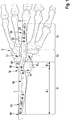
- Figure 2 shows the plate 10 in a side view
- the plate 10 has a second curved area 17 between the proximal attachment zone 14 and the distal attachment zone 15, which is curved in a U-shape in a side view.
- the second curved area 17 can be pushed under the soft parts of the joint, which are not shown in the figure.
- the location 20 of the second change in direction of the second curved area 17, where the greatest vertical deflection with an offset V 2 is typically present, can have an inner radius R i2 of 12 mm-18 mm, in particular 12 mm.
- the vertical offset V 2 is approximately 3 mm.
- the location 20 with the greatest vertical deflection can have a distance A 2 between 50 mm and 70 mm, preferably 61 mm, from the distal end 21 of the plate 10.
- the location 20 of the second change in direction of the second curved region 17 can be arranged at a distance D 2 between 10 mm to 12 mm, preferably 11 mm, from the proximal end 25 of the middle finger bone.
- the longitudinal axis 26 of the proximal section 11 encloses an angle ⁇ of approximately 12 ° with a longitudinal axis 27 of the distal section 12 in a side view.
- the thickness of the plate 10 decreases towards the ends 19, 21 of the plate.
- Hand big Hand medium Hand small Length (mm) 230 200 170 width (mm) 12 10 8th Thickness (mm) 5 3.5 2 D 1 (mm) 13 11 9 A 1 (mm) 105 120 135 D 2 (mm) 12 11 10 A 2 (mm) 60 55 45 R i1 (mm) 25th 19th 5 R i2 (mm) 20th 12 2 ⁇ (°) 12 12 12 V 1 (mm) 8th 5 3 V 2 (mm) 7th 5 3
Landscapes
- Health & Medical Sciences (AREA)
- Orthopedic Medicine & Surgery (AREA)
- Surgery (AREA)
- Life Sciences & Earth Sciences (AREA)
- Heart & Thoracic Surgery (AREA)
- Nuclear Medicine, Radiotherapy & Molecular Imaging (AREA)
- Engineering & Computer Science (AREA)
- Biomedical Technology (AREA)
- Neurology (AREA)
- Medical Informatics (AREA)
- Molecular Biology (AREA)
- Animal Behavior & Ethology (AREA)
- General Health & Medical Sciences (AREA)
- Public Health (AREA)
- Veterinary Medicine (AREA)
- Surgical Instruments (AREA)
Priority Applications (9)
| Application Number | Priority Date | Filing Date | Title |
|---|---|---|---|
| EP19192018.0A EP3777735A1 (fr) | 2019-08-16 | 2019-08-16 | Plaque de pontage temporaire des fragments d'une fracture |
| AU2020334184A AU2020334184A1 (en) | 2019-08-16 | 2020-08-12 | Plate for temporarily bridging fragments of a fracture |
| US17/634,297 US20220280211A1 (en) | 2019-08-16 | 2020-08-12 | Plate for temporarily bridging fragments of a fracture |
| PCT/EP2020/072657 WO2021032571A1 (fr) | 2019-08-16 | 2020-08-12 | Plaque de pontage temporaire de fragments d'une fracture |
| EP20756846.0A EP4013322A1 (fr) | 2019-08-16 | 2020-08-12 | Plaque de pontage temporaire de fragments d'une fracture |
| JP2022509725A JP2022544614A (ja) | 2019-08-16 | 2020-08-12 | 骨折の破片の一時的なブリッジのためのプレート |
| CN202080057321.9A CN114222538A (zh) | 2019-08-16 | 2020-08-12 | 用于临时桥接骨折碎片的板 |
| MX2022001931A MX2022001931A (es) | 2019-08-16 | 2020-08-12 | Placa para unir temporalmente los fragmentos de una fractura. |
| BR112022001306A BR112022001306A2 (pt) | 2019-08-16 | 2020-08-12 | Placa para a cobertura temporária de fragmentos de uma fratura |
Applications Claiming Priority (1)
| Application Number | Priority Date | Filing Date | Title |
|---|---|---|---|
| EP19192018.0A EP3777735A1 (fr) | 2019-08-16 | 2019-08-16 | Plaque de pontage temporaire des fragments d'une fracture |
Publications (1)
| Publication Number | Publication Date |
|---|---|
| EP3777735A1 true EP3777735A1 (fr) | 2021-02-17 |
Family
ID=67659049
Family Applications (2)
| Application Number | Title | Priority Date | Filing Date |
|---|---|---|---|
| EP19192018.0A Withdrawn EP3777735A1 (fr) | 2019-08-16 | 2019-08-16 | Plaque de pontage temporaire des fragments d'une fracture |
| EP20756846.0A Pending EP4013322A1 (fr) | 2019-08-16 | 2020-08-12 | Plaque de pontage temporaire de fragments d'une fracture |
Family Applications After (1)
| Application Number | Title | Priority Date | Filing Date |
|---|---|---|---|
| EP20756846.0A Pending EP4013322A1 (fr) | 2019-08-16 | 2020-08-12 | Plaque de pontage temporaire de fragments d'une fracture |
Country Status (8)
| Country | Link |
|---|---|
| US (1) | US20220280211A1 (fr) |
| EP (2) | EP3777735A1 (fr) |
| JP (1) | JP2022544614A (fr) |
| CN (1) | CN114222538A (fr) |
| AU (1) | AU2020334184A1 (fr) |
| BR (1) | BR112022001306A2 (fr) |
| MX (1) | MX2022001931A (fr) |
| WO (1) | WO2021032571A1 (fr) |
Citations (7)
| Publication number | Priority date | Publication date | Assignee | Title |
|---|---|---|---|---|
| US5853413A (en) | 1997-04-18 | 1998-12-29 | Bristol-Myers Squibb Company | Wrist fusion plate |
| US20040102777A1 (en) * | 2002-11-19 | 2004-05-27 | Huebner Randall J. | Deformable bone plates |
| US20090248084A1 (en) * | 2008-03-27 | 2009-10-01 | Beat Hintermann | Systems and methods for performing ankle arthrodesis in a human patient |
| DE102008039693A1 (de) | 2008-08-26 | 2010-03-11 | Normed Medizin-Technik Vertriebs-Gmbh | Handgelenkarthrodeseplatte sowie Sortiment |
| US20100131013A1 (en) * | 2008-11-24 | 2010-05-27 | Ralph James D | Clavicle plate and screws |
| US20100217327A1 (en) * | 2009-02-24 | 2010-08-26 | Vancelette David W | Plate and system for lateral treatment of a fracture of the calcaneus |
| EP2606843A1 (fr) | 2011-12-22 | 2013-06-26 | Stryker Trauma SA | Plaque de fusion pour le poignet |
Family Cites Families (2)
| Publication number | Priority date | Publication date | Assignee | Title |
|---|---|---|---|---|
| US7250053B2 (en) * | 2003-03-27 | 2007-07-31 | Depuy Products, Inc. | Low profile distal radius fracture fixation plate |
| ES2525129T3 (es) * | 2009-12-30 | 2014-12-17 | Medartis Ag | Placa de osteosíntesis para el tratamiento de fracturas próximas a una articulación u osteotomías |
-
2019
- 2019-08-16 EP EP19192018.0A patent/EP3777735A1/fr not_active Withdrawn
-
2020
- 2020-08-12 MX MX2022001931A patent/MX2022001931A/es unknown
- 2020-08-12 WO PCT/EP2020/072657 patent/WO2021032571A1/fr unknown
- 2020-08-12 AU AU2020334184A patent/AU2020334184A1/en active Pending
- 2020-08-12 JP JP2022509725A patent/JP2022544614A/ja active Pending
- 2020-08-12 EP EP20756846.0A patent/EP4013322A1/fr active Pending
- 2020-08-12 CN CN202080057321.9A patent/CN114222538A/zh active Pending
- 2020-08-12 US US17/634,297 patent/US20220280211A1/en active Pending
- 2020-08-12 BR BR112022001306A patent/BR112022001306A2/pt unknown
Patent Citations (7)
| Publication number | Priority date | Publication date | Assignee | Title |
|---|---|---|---|---|
| US5853413A (en) | 1997-04-18 | 1998-12-29 | Bristol-Myers Squibb Company | Wrist fusion plate |
| US20040102777A1 (en) * | 2002-11-19 | 2004-05-27 | Huebner Randall J. | Deformable bone plates |
| US20090248084A1 (en) * | 2008-03-27 | 2009-10-01 | Beat Hintermann | Systems and methods for performing ankle arthrodesis in a human patient |
| DE102008039693A1 (de) | 2008-08-26 | 2010-03-11 | Normed Medizin-Technik Vertriebs-Gmbh | Handgelenkarthrodeseplatte sowie Sortiment |
| US20100131013A1 (en) * | 2008-11-24 | 2010-05-27 | Ralph James D | Clavicle plate and screws |
| US20100217327A1 (en) * | 2009-02-24 | 2010-08-26 | Vancelette David W | Plate and system for lateral treatment of a fracture of the calcaneus |
| EP2606843A1 (fr) | 2011-12-22 | 2013-06-26 | Stryker Trauma SA | Plaque de fusion pour le poignet |
Also Published As
| Publication number | Publication date |
|---|---|
| BR112022001306A2 (pt) | 2022-06-07 |
| MX2022001931A (es) | 2022-03-11 |
| CN114222538A (zh) | 2022-03-22 |
| EP4013322A1 (fr) | 2022-06-22 |
| WO2021032571A1 (fr) | 2021-02-25 |
| US20220280211A1 (en) | 2022-09-08 |
| AU2020334184A1 (en) | 2022-02-24 |
| JP2022544614A (ja) | 2022-10-19 |
Similar Documents
| Publication | Publication Date | Title |
|---|---|---|
| DE69918534T2 (de) | Orthopädischer monolateraler aussenfixateur | |
| EP2340777B1 (fr) | Plaque d'ostéosynthèse destinée au traitement de fractures proches d'une articulation ou d'ostéotomies | |
| EP1682020B1 (fr) | Dispositif de fixation osseuse | |
| DE60202037T2 (de) | Befestigungsplatte für Knochen eines Gelenks, insbesondere für ein Metatarsophalangealgelenk | |
| EP0515828B1 (fr) | Dispositif de stabilisation du trochanter | |
| DE69725567T2 (de) | Haltetransplantat | |
| EP1684651A1 (fr) | Plaque pour stabiliser des fractures distales de rayons | |
| DE202005019277U1 (de) | Knochenplatte mit wenigstens zwei Langlöchern und Knochenplattensystem | |
| EP1927322B1 (fr) | Dispositif de positionnement des os tubulaires | |
| DE10125092A1 (de) | Osteoxyntheseplatte (Titan) zur inneren Schienung von Knochenbrüchen am körperfernen Ende der menschlichen Speiche zur Anlage an der Streckseite des Knochens - genannt: Y-Platte | |
| EP0425625B1 (fr) | Eclisse pour doigts | |
| EP0423280B1 (fr) | Systeme de fixation pour fractures d'os tubulaires | |
| EP2158864A2 (fr) | Plaque d'arthrodèse du poignet et assortiment | |
| EP3232962B1 (fr) | Plaque d'ostéosynthèse, ensembles chirurgicaux et ensembles de reconstruction | |
| EP3777735A1 (fr) | Plaque de pontage temporaire des fragments d'une fracture | |
| EP1679044B1 (fr) | Set pour la création d'un implant d'ostéosynthèse | |
| DE102013210638B4 (de) | Fingergelenkprothese mit selbstjustierenden Verankerungsleisten | |
| DE102017101882A1 (de) | Arbeitsmittel zur Stabilisierung von Knochenbrüchen | |
| EP2934355B1 (fr) | Clou intramedullaire à verrouillage comprenant des trous pour un fil de guidage | |
| EP2194896B1 (fr) | Dispositif d'ostéosynthèse à la suite de fractures et de luxations de l'humérus | |
| DE102014119011A1 (de) | Positionierungsvorrichtung für die Anbringung von Befestigungselementen in Knochen | |
| DE102022128396A1 (de) | Orthopädietechnische Einrichtung mit pivotierender Drehachse | |
| EP3530224A1 (fr) | Plaque d'arthrodèse du poignet | |
| DE202013002564U1 (de) | Befestigungsplatte mit Gleitloch | |
| DE102014203314A1 (de) | Chirurgisches Implantat zur Stabilisierung von Halswirbelknochen |
Legal Events
| Date | Code | Title | Description |
|---|---|---|---|
| PUAI | Public reference made under article 153(3) epc to a published international application that has entered the european phase |
Free format text: ORIGINAL CODE: 0009012 |
|
| STAA | Information on the status of an ep patent application or granted ep patent |
Free format text: STATUS: THE APPLICATION HAS BEEN PUBLISHED |
|
| AK | Designated contracting states |
Kind code of ref document: A1 Designated state(s): AL AT BE BG CH CY CZ DE DK EE ES FI FR GB GR HR HU IE IS IT LI LT LU LV MC MK MT NL NO PL PT RO RS SE SI SK SM TR |
|
| AX | Request for extension of the european patent |
Extension state: BA ME |
|
| STAA | Information on the status of an ep patent application or granted ep patent |
Free format text: STATUS: THE APPLICATION IS DEEMED TO BE WITHDRAWN |
|
| 18D | Application deemed to be withdrawn |
Effective date: 20210818 |