EP3777735A1 - Plate for temporary bridging of fragments of a fracture - Google Patents
Plate for temporary bridging of fragments of a fracture Download PDFInfo
- Publication number
- EP3777735A1 EP3777735A1 EP19192018.0A EP19192018A EP3777735A1 EP 3777735 A1 EP3777735 A1 EP 3777735A1 EP 19192018 A EP19192018 A EP 19192018A EP 3777735 A1 EP3777735 A1 EP 3777735A1
- Authority
- EP
- European Patent Office
- Prior art keywords
- plate
- proximal
- distal
- section
- bone
- Prior art date
- Legal status (The legal status is an assumption and is not a legal conclusion. Google has not performed a legal analysis and makes no representation as to the accuracy of the status listed.)
- Withdrawn
Links
Images

Classifications
-
- A—HUMAN NECESSITIES
- A61—MEDICAL OR VETERINARY SCIENCE; HYGIENE
- A61B—DIAGNOSIS; SURGERY; IDENTIFICATION
- A61B17/00—Surgical instruments, devices or methods, e.g. tourniquets
- A61B17/56—Surgical instruments or methods for treatment of bones or joints; Devices specially adapted therefor
- A61B17/58—Surgical instruments or methods for treatment of bones or joints; Devices specially adapted therefor for osteosynthesis, e.g. bone plates, screws, setting implements or the like
- A61B17/68—Internal fixation devices, including fasteners and spinal fixators, even if a part thereof projects from the skin
- A61B17/80—Cortical plates, i.e. bone plates; Instruments for holding or positioning cortical plates, or for compressing bones attached to cortical plates
- A61B17/8061—Cortical plates, i.e. bone plates; Instruments for holding or positioning cortical plates, or for compressing bones attached to cortical plates specially adapted for particular bones
-
- A—HUMAN NECESSITIES
- A61—MEDICAL OR VETERINARY SCIENCE; HYGIENE
- A61B—DIAGNOSIS; SURGERY; IDENTIFICATION
- A61B17/00—Surgical instruments, devices or methods, e.g. tourniquets
- A61B17/56—Surgical instruments or methods for treatment of bones or joints; Devices specially adapted therefor
- A61B17/58—Surgical instruments or methods for treatment of bones or joints; Devices specially adapted therefor for osteosynthesis, e.g. bone plates, screws, setting implements or the like
- A61B17/68—Internal fixation devices, including fasteners and spinal fixators, even if a part thereof projects from the skin
- A61B17/80—Cortical plates, i.e. bone plates; Instruments for holding or positioning cortical plates, or for compressing bones attached to cortical plates
- A61B17/808—Instruments for holding or positioning bone plates, or for adjusting screw-to-plate locking mechanisms
-
- A—HUMAN NECESSITIES
- A61—MEDICAL OR VETERINARY SCIENCE; HYGIENE
- A61B—DIAGNOSIS; SURGERY; IDENTIFICATION
- A61B17/00—Surgical instruments, devices or methods, e.g. tourniquets
- A61B17/56—Surgical instruments or methods for treatment of bones or joints; Devices specially adapted therefor
- A61B17/58—Surgical instruments or methods for treatment of bones or joints; Devices specially adapted therefor for osteosynthesis, e.g. bone plates, screws, setting implements or the like
- A61B17/68—Internal fixation devices, including fasteners and spinal fixators, even if a part thereof projects from the skin
- A61B17/84—Fasteners therefor or fasteners being internal fixation devices
Definitions
- the invention relates to a plate for the temporary bridging of fragments of a fracture.
- a surgeon can implant a joint plate.
- One or more bone fastening elements are usually attached to the joint bones at desired locations with the plate.
- the plate is fixed in the desired position so that the bones of the joint have the desired orientations in relation to one another.
- a wrist arthrosis plate which has a widened carpal bone fixing section with through holes which are spaced transversely to the longitudinal direction of the wrist arthrosis plate.
- the wrist arthrosis plate has a material thickness of less than 3mm.
- the carpal bone fixation section is convex, that is, it rises dorsally.
- the section can also be spoon-shaped.
- FIG. 11 shows a wrist fusion plate with a proximal and a distal end, each extending away from a saddle area and each defining a longitudinal axis.
- the longitudinal axis of the distal end is not aligned axially to the longitudinal axis of the proximal end in the medial-lateral direction.
- the object is achieved by a plate for the temporary bridging of fragments of a fracture with the features of the independent claim.
- the plate is preferably used to bridge bone fragments of a mammal, in particular a human.
- the plate has a proximal portion, a distal portion, and an intermediate portion disposed between the proximal portion and the distal portion.
- the proximal section has a proximal attachment zone which is designed to be applied to and attached to a first tubular bone.
- the proximal fastening zone lies in particular in the proximal area of the plate and takes up a maximum of 30% -50% and in particular a maximum of 25% -30% of the total length of the plate.
- the proximal fastening zone is formed by that proximal area of the plate in which there are through holes, the distance between which does not exceed 20 mm. In other words, this means that through holes can also be present in other sections in the proximal area of the plate.
- the fastening zone is only defined by a group of through holes which are sufficiently close to one another.
- the proximal fastening zone can also be regarded as that region of the proximal section which has essentially no curvature.
- the proximal section can define a first longitudinal axis along which it essentially extends.
- the longitudinal axis of a section can be defined by a linear interpolation of centers of gravity of cut surfaces of the plate, the cuts taking place perpendicular to the main direction of propagation of the section.
- the cut surfaces can, for example, have contours which are given by the width and the thickness of the plate in the cutting plane.
- the proximal fastening zone is preferably equipped with through holes into which a fastening element, such as a nail, screw or wire, can be inserted.
- the distal section has a distal attachment zone which is designed to be applied and attached to a second tubular bone.
- the distal fastening zone lies in particular in the distal area of the plate and takes up a maximum of 30% -50% and in particular a maximum of 25% -30% of the total length of the plate.
- the distal fastening zone is formed by that distal area of the plate in which there are through holes, the respective distance from one another of which does not exceed a length of 20 mm.
- the fastening zone is only defined by a group of through holes which are sufficiently close to one another.
- the distal fastening zone can also be regarded as that region of the distal section which has essentially no curvature.
- the distal section can define a second longitudinal axis along which it essentially extends.
- the longitudinal axis can result from a linear interpolation of the cut surface centroids.
- the distal fastening zone is preferably equipped with through holes into which a fastening element, such as a nail, screw or wire, can be inserted.
- the intermediate section is designed to bridge a joint between the first tubular bone and the second tubular bone and thereby at least one further bone.
- the bridging takes place without attachment to the at least one further bone in the bridged area.
- No through hole therefore needs to be arranged in the intermediate section. It can be free of through holes for receiving fasteners.
- the proximal attachment zone can, for example, be designed to be applied and attached to a radius, while the distal attachment zone can be designed to be applied and attached to a metacarpal bone.
- the proximal attachment zone can be designed to be attached to a tibia or talus, and the distal attachment zone to a metatarsal bone.
- the dimensions given below relate to applications on the radius and metacarpal bones, unless otherwise stated.
- the dimensions of the plate must be adapted according to the size relationships.
- the plate has at least one curved area between the proximal fastening zone and the distal fastening zone.
- a curved area is understood to mean an area in which the plate changes its direction at least once, preferably at least twice, with respect to an alignment axis, for example with respect to the first or second longitudinal axis.
- the plate is preferably designed essentially as an elongated, flat body, with a length that is greater than the width, in particular more than 10 times, and a thickness or material thickness that is smaller than the width.
- the width is, for example, between 2 mm and 25 mm, preferably between 5 mm and 15 mm, and the material thickness is, for example, between 1 mm and 5 mm, preferably between 2.8 mm and 3.8 mm, particularly preferably 3.4 mm.
- the plate typically has a total length of 10 cm-30 cm, preferably 15-25 cm, particularly preferably about 20 cm.
- the plate is preferably made of metal, for example titanium or a titanium alloy, or of implant steel.
- metal for example titanium or a titanium alloy, or of implant steel.
- Other biocompatible materials are also conceivable, in particular also carbon, implantable plastics and combinations thereof.
- the plate extends essentially in an orientation which can preferably coincide with the longitudinal direction of one of the long bones, for example the proximal and / or distal long bones.
- the plate preferably has two longitudinal axes corresponding to the longitudinal axes of the proximal and distal sections which include an angle according to the desired joint fixation.
- the longitudinal axes can coincide at least in a lateral view or run parallel to one another.
- a first curved region can be curved in plan view.
- the top view is directed to the side of the plate body on which the length and width can be seen.
- the first curved area is preferably Z-shaped or U-shaped.
- the alignment changes twice in one direction from the proximal end to the distal end; in the case of a U-shaped curvature, there is a change in direction three times with respect to a substantial alignment of the proximal and / or distal section, in particular the respective longitudinal axis.
- the first curved area is preferably designed in such a way that irritation of soft parts is excluded or at least minimized, so that in particular space is provided for an extensor or flexor tendon.
- the tendons are constantly irritated while the wrist is immobilized, this can lead to injury to the tendons and stiffening of the fingers.
- the curved area ensures that the tendons have room and are not affected by the plate.
- An area that is U-shaped in plan view can be used, for example, when a radius is connected to a middle finger bone.
- the curvature leaves room for the finger tendons.
- a region that is curved in a Z-shape in plan view can be used, for example, when a radius is connected to an index finger bone or a ring finger bone.
- the curvature leaves room for the finger tendons.
- the curvature of the first curved area can have a change of direction with an inner radius (Ri1) of 15mm-22mm at the inner edge, in particular 19mm. In particular, all changes in direction have a corresponding inner radius.
- the curvature of the first curved area can alternatively or additionally be designed in such a way that a lateral / lateral offset is created which corresponds to at least half the width of the plate, typically at least approximately 3 mm.
- the first curved area can have straight intermediate sections.
- the first curved area can alternatively or additionally in the direction from the proximal end to the distal end a first change of direction by an angle of 10 ° to 60 °, a second change of direction by an angle of 10 ° to 60 ° and optionally a third change of direction by an angle of 10 ° to 60 °.
- the direction changes in each case in such a way that a Z-shape or a U-shape is formed in plan view.
- the plate is preferably designed in such a way that the first curved region can be positioned at the distal end of the first tubular bone.
- the first curved area can lie in the proximal section and can also have through holes for fastening.
- At least one fastening hole is preferably provided in at least one area in which a change in direction takes place, preferably in the area of the second change in direction.
- the location of the second change in direction of the first curved region, where there is typically a greatest lateral deflection of the plate, is at a distance of between 110 mm and 130 mm, preferably 120 mm, from the proximal end of the plate.
- the plate can be designed so that the location of the second change in direction of the first curved area can be arranged at a distance of between 10 mm to 12 mm, preferably 11 mm, from the distal end of the first tubular bone (1).
- the location of the second change in direction is at a distance of 10 mm to 12 mm, preferably approximately 11 mm, from the proximal end of the intermediate section.
- the second change in direction can be arranged at a distance of 25 mm-45 mm, preferably 30 mm-40 mm, from the first change in direction.
- the plate has a second curved area which is curved in a side view.
- the side view is directed to the side of the plate body on which the length and thickness can be seen.
- the second curved area is preferably curved in a Z-shape or U-shape.
- the second curved area is preferably arranged in the intermediate section.
- the second curved area preferably does not contain any through holes and is therefore not intended to be fixed to a bone.
- the curvature of the second curved area is designed such that the second curved area can be pushed under the soft parts of the joint.
- the plate can then be slidable under the tendons of the joint, for example.
- a plate with a first and a second curved area can thus be guided around the soft tissues and leave this space for movement.
- the second curved area allows the plate to automatically assume the optimal position when it is attached, provided the size of the plate has been selected to suit the patient.
- the plate is designed as a wrist plate, it can be positioned on the distal radius in the extensor tendon compartments.
- the curvature of the second curved area can result in a change of direction with an inner radius (Ri2) of 12mm-18mm on the to Have inner curvature pointing edge of the plate, in particular of 12mm. In particular, all changes in direction have such an inner radius.
- the curvature of the second curved area can alternatively or additionally be selected so that the vertical offset (ie the offset with respect to the plane of the plate) is 1mm-10mm, preferably 3mm-4mm.
- the second curved area can have straight intermediate sections.
- the second curved area can in the direction from the proximal end to the distal end a first change of direction by an angle of 10 ° to 60 °, a second change of direction by an angle of 10 ° to 60 ° and optionally a third change of direction by an angle of 10 ° to 60 °.
- the direction changes in each case in such a way that a Z-shape or a U-shape is formed in a side view.
- the changes in direction are preferably carried out in such a way that after a first, second and, if necessary, third change in direction (in a direction from the proximal end to the distal end), the longitudinal axes of the proximal and distal sections in a side view enclose the angle of the desired joint position, i.e. the angle that the should include long bones to be connected.
- the second curved area has a location of the second change in direction, where the greatest vertical deflection of the plate is typically present.
- This location has, for example, a distance between 50 mm and 70 mm, preferably 61 mm, from the distal end of the plate.
- the plate is designed so that the location of the second change in direction of the second curved area can be arranged at a distance of between 10 mm to 15 mm, preferably 11 mm, from the proximal end of the second long bone.
- the point of the second curved area having the greatest lateral distance from the area of the plate before the first change in direction is between 10 mm and 12 mm, preferably 11 mm, from the proximal end of the distal section.
- the through holes in the proximal fastening zone and / or in the first curved area and / or in the distal fastening zone are designed as at least one screw hole, elongated hole and / or K-wire hole.
- the plate can be pre-fixed using the K-wire hole so that the position can be checked under X-ray control before screwing.
- the longitudinal axis of the proximal section can form an angle of + 45 ° to -45 °, preferably 0 °, with the longitudinal axis of the distal section in plan view.
- a longitudinal axis can be arranged, for example, along the longitudinal axis of the distal tubular bone, which as a rule has a smaller diameter.
- the longitudinal axis of the proximal section can be fixed in plan view State can also be inclined relative to the longitudinal axis of the proximal tubular bone, depending on the bone model.
- a number of attachment holes along the longitudinal axis of the proximal end can be placed on a shorter piece of bone. The plate can therefore be made shorter overall, with the same fastening stability being achieved.
- the longitudinal axis of the proximal section can form an angle of ⁇ 45 ° to + 45 ° with the longitudinal axis of the distal section in a side view.
- the longitudinal axes preferably enclose an angle of 12 ° in a side view.
- the thickness of the plate in the proximal section decreases towards the proximal end and / or the thickness of the plate in the distal section decreases towards the distal end.
- the material thickness of a flat plate becomes smaller towards the ends.
- the plate can then be brought into the joint area more easily and discontinuities in the bending moments are prevented at the transition between plate and bone.
- the object is also achieved by a method for treating a complex joint fracture, the joint being located between two tubular bones of a human patient.
- a plate is provided, preferably as described above, with a proximal section, a distal section and an intermediate section which is arranged between the proximal section and the distal section.
- the proximal section has a proximal attachment zone which is applied to and attached to a first tubular bone.
- the distal section has a distal attachment zone which is applied to and attached to the second tubular bone.
- the intermediate section bridges the joint between the first tubular bone and the second tubular bone and thereby at least one further bone, in particular without attachment to the at least one further bone.
- the plate between the proximal attachment zone and the distal attachment zone has at least one curved area.
- the proximal attachment zone can be created and attached to a radius and the distal attachment zone to a metacarpal bone.
- the proximal attachment zone can be attached to a tibia and the distal attachment zone can be attached to a metatarsal bone.
- Figure 1 shows a plate 10 for the temporary bridging of fragments of a wrist fracture in plan view.
- the plate 10 has a proximal section 11, a distal section 12 and an intermediate section 13 which is arranged between the proximal section 11 and the distal section 12.
- the proximal section 11 has a proximal fastening zone 14 which is designed to be placed on and fastened to a first tubular bone 1, here a radius.
- the distal section 12 has a distal fastening zone 15, which is placed and fastened on a second tubular bone 2, here a middle finger bone.
- the intermediate section 13 bridges the wrist 3 between the radius 1 and the middle finger bone 2 and lies over the carpal bone.
- the intermediate section 13 is not attached to the carpal bone.
- the plate 10 has a first curved region 16 between the proximal fastening zone 14 and the distal fastening zone 15 which is curved in a U-shape.
- the first curved region 16 is positioned at the distal end of the radius 1.
- the plate 10 is therefore designed in such a way that pinching of extensor or flexor tendons (not shown here) can be prevented.
- the curvature of the first curved region 16 has a location 18 of the second change in direction with an inner radius R i1 of 15 mm-22 mm, in particular 19 mm.
- the lateral offset V 1 corresponds approximately to the mean width of the plate and is approximately 10 mm.
- the location 18 of the second change in direction with the greatest lateral deflection with the offset V 1 can have a distance A 1 between 110 mm and 130 mm, preferably 120 mm, from the proximal end 19 of the plate 10.
- the location 18 with the greatest lateral deflection is preferably arranged at a distance D 1 between 10 mm and 12 mm, preferably 11 mm, from the distal end of the radius 1.
- Screw holes 22 are provided in the proximal fastening zone 14, in the first curved region 16 and in the distal fastening zone 15.
- an elongated hole 23 is provided in each of the proximal fastening zone 14 and in the distal fastening zone 15.
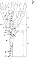
- Figure 2 shows the plate 10 in a side view
- the plate 10 has a second curved area 17 between the proximal attachment zone 14 and the distal attachment zone 15, which is curved in a U-shape in a side view.
- the second curved area 17 can be pushed under the soft parts of the joint, which are not shown in the figure.
- the location 20 of the second change in direction of the second curved area 17, where the greatest vertical deflection with an offset V 2 is typically present, can have an inner radius R i2 of 12 mm-18 mm, in particular 12 mm.
- the vertical offset V 2 is approximately 3 mm.
- the location 20 with the greatest vertical deflection can have a distance A 2 between 50 mm and 70 mm, preferably 61 mm, from the distal end 21 of the plate 10.
- the location 20 of the second change in direction of the second curved region 17 can be arranged at a distance D 2 between 10 mm to 12 mm, preferably 11 mm, from the proximal end 25 of the middle finger bone.
- the longitudinal axis 26 of the proximal section 11 encloses an angle ⁇ of approximately 12 ° with a longitudinal axis 27 of the distal section 12 in a side view.
- the thickness of the plate 10 decreases towards the ends 19, 21 of the plate.
- Hand big Hand medium Hand small Length (mm) 230 200 170 width (mm) 12 10 8th Thickness (mm) 5 3.5 2 D 1 (mm) 13 11 9 A 1 (mm) 105 120 135 D 2 (mm) 12 11 10 A 2 (mm) 60 55 45 R i1 (mm) 25th 19th 5 R i2 (mm) 20th 12 2 ⁇ (°) 12 12 12 V 1 (mm) 8th 5 3 V 2 (mm) 7th 5 3
Abstract
Die Erfindung betrifft eine Platte zur temporären Überbrückung von Fragmenten einer Fraktur mit einem proximalen Abschnitt (11), einem distalen Abschnitt (12) und einem Zwischenabschnitt (13), der zwischen dem proximalen Abschnitt (11) und dem distalen Abschnitt (12) angeordnet ist. Der proximale Abschnitt (11) weist eine proximale Befestigungszone (14) auf, die dazu ausgebildet ist, an einem ersten Röhrenknochen (1) angelegt und befestigt zu werden. Der distale Abschnitt (12) weist eine distale Befestigungszone (15) auf, die dazu ausgebildet ist, an einem zweiten Röhrenknochen (2) angelegt und befestigt zu werden. Der Zwischenabschnitt (13) ist dazu ausgebildet, ein Gelenk (3) zwischen dem ersten Röhrenknochen (1) und dem zweiten Röhrenknochen (2) und dabei mindestens einen weiteren Knochen, insbesondere ohne Befestigung an dem mindestens einen weiteren Knochen, zu überbrücken. Die Platte (10) weist zwischen der proximalen Befestigungszone (14) und der distalen Befestigungszone (15) mindestens einen gebogenen Bereich (16, 17) auf.The invention relates to a plate for temporarily bridging fragments of a fracture with a proximal section (11), a distal section (12) and an intermediate section (13) which is arranged between the proximal section (11) and the distal section (12) . The proximal section (11) has a proximal fastening zone (14) which is designed to be placed on and fastened to a first tubular bone (1). The distal section (12) has a distal fastening zone (15) which is designed to be placed on and fastened to a second tubular bone (2). The intermediate section (13) is designed to bridge a joint (3) between the first tubular bone (1) and the second tubular bone (2) and at least one additional bone, in particular without attachment to the at least one additional bone. The plate (10) has at least one curved area (16, 17) between the proximal fastening zone (14) and the distal fastening zone (15).
Description
Die Erfindung betrifft eine Platte zur temporären Überbrückung von Fragmenten einer Fraktur.The invention relates to a plate for the temporary bridging of fragments of a fracture.
Auf dem Gebiet der Behandlung von Gelenksstörungen, zum Beispiel nach chirurgischen Eingriffen zum Wiederausrichten von falsch ausgerichteten oder deformierten Handgelenksknochen, kann ein Chirurg eine Gelenksplatte implantieren. Mit der Platte werden in der Regel ein oder mehrere Knochenbefestigungselemente an gewünschten Stellen der Gelenksknochen angebracht. Die Platte wird in der gewünschten Position fixiert, so dass die Knochen des Gelenks die gewünschten Ausrichtungen in Bezug aufeinander haben.In the field of treating joint disorders, for example after surgery to realign misaligned or deformed wrist bones, a surgeon can implant a joint plate. One or more bone fastening elements are usually attached to the joint bones at desired locations with the plate. The plate is fixed in the desired position so that the bones of the joint have the desired orientations in relation to one another.
Das komplizierte Netzwerk von Sehnen, Muskeln und Nervenenden im Gelenk kann eine ordnungsgemäße Fixierung erschweren. Der Chirurg muss beim Fixieren der Gelenkplatte so gut wie möglich darauf achten, das umliegende Gewebe nicht zu beschädigen.The intricate network of tendons, muscles, and nerve endings in the joint can make proper fixation difficult. When fixing the joint plate, the surgeon must be careful not to damage the surrounding tissue.
Aus der
In der
Die
Bei grossräumigen komplexen Frakturen (Polytrauma) kann entschieden werden, die Fragmente gar nicht detailliert zu versorgen, sondern nur temporär zu überbrücken, da man den Patienten nicht noch mehr belasten möchte. Durch äussere Reposition wird versucht, die einzelnen Knochenstücke in ihre ursprüngliche Lage zu bringen (Ligamentotaxis). Sie heilen dann dort mehr oder weniger gut aus. Zur Überbrückung dieser Trümmerzone kommen sogenannte Spannplatten zum Einsatz. Am Handgelenk wird beispielweise der Radiusschaft mit der Mittelhand verbunden, wobei die Finger beweglich bleiben können.In the case of large-scale complex fractures (multiple trauma), a decision can be made not to treat the fragments in detail at all, but only to bridge them temporarily, as one does not want to burden the patient any further. External repositioning attempts to bring the individual pieces of bone into their original position (ligamentotaxis). They then heal more or less well there. So-called clamping plates are used to bridge this rubble zone. On the wrist, for example, the radial shaft is connected to the metacarpal, whereby the fingers can remain mobile.
Für die temporäre Überbrückung eines Handgelenks werden zumeist einfach geformte, sich in einer Längsrichtung erstreckende Platten verwendet.For the temporary bridging of a wrist, simply shaped plates that extend in a longitudinal direction are mostly used.
Es ist die Aufgabe der Erfindung, eine Platte zur temporären Überbrückung von Fragmenten einer Fraktur vorzustellen, welche die Nachteile des Bekannten vermeidet und welche insbesondere dafür sorgt, dass Irritationen von Weichteilen ausgeschlossen oder zumindest minimiert werden.It is the object of the invention to present a plate for the temporary bridging of fragments of a fracture which avoids the disadvantages of the known and which in particular ensures that irritation of soft tissues is excluded or at least minimized.
Die Aufgabe wird gelöst durch eine Platte zur temporären Überbrückung von Fragmenten einer Fraktur mit den Merkmalen des unabhängigen Anspruchs.The object is achieved by a plate for the temporary bridging of fragments of a fracture with the features of the independent claim.
Die Platte dient bevorzugt zum Überbrücken von Knochenfragmenten eines Säugetiers, insbesondere eines Menschen.The plate is preferably used to bridge bone fragments of a mammal, in particular a human.
Die Platte weist einen proximalen Abschnitt, einen distalen Abschnitt und einen Zwischenabschnitt auf, der zwischen dem proximalen Abschnitt und dem distalen Abschnitt angeordnet ist.The plate has a proximal portion, a distal portion, and an intermediate portion disposed between the proximal portion and the distal portion.
Der proximale Abschnitt besitzt eine proximale Befestigungszone, die dazu ausgebildet ist, an einem ersten Röhrenknochen angelegt und befestigt zu werden.The proximal section has a proximal attachment zone which is designed to be applied to and attached to a first tubular bone.
Die proximale Befestigungszone liegt insbesondere im proximalen Bereich der Platte und nimmt maximal 30%-50% und insbesondere maximal 25%-30% der Gesamtlänge der Platte ein.The proximal fastening zone lies in particular in the proximal area of the plate and takes up a maximum of 30% -50% and in particular a maximum of 25% -30% of the total length of the plate.
Alternativ oder zusätzlich ist die proximale Befestigungszone durch denjenigen proximalen Bereich der Platte gebildet, in dem sich Durchgangslöcher befinden, deren jeweiliger Abstand zueinander die Länge von 20mm nicht überschreitet. Mit anderen Worten heisst dies, dass im proximalen Bereich der Platte auch in anderen Abschnitten Durchgangslöcher vorhanden sein können. Die Befestigungszone wird aber nur durch eine Gruppe von Durchgangslöchern definiert, welche ausreichend nah beieinander liegen.Alternatively or additionally, the proximal fastening zone is formed by that proximal area of the plate in which there are through holes, the distance between which does not exceed 20 mm. In other words, this means that through holes can also be present in other sections in the proximal area of the plate. The fastening zone is only defined by a group of through holes which are sufficiently close to one another.
Die proximale Befestigungszone kann auch als derjenige Bereich des proximalen Abschnitts betrachtet werden, welcher im Wesentlichen keine Krümmung aufweist.The proximal fastening zone can also be regarded as that region of the proximal section which has essentially no curvature.
Der proximale Abschnitt kann in Draufsicht und/oder in seitlicher Ansicht eine erste Längsachse definieren, entlang derer er sich im Wesentlichen erstreckt.In plan view and / or in side view, the proximal section can define a first longitudinal axis along which it essentially extends.
Die Längsachse eines Abschnitts kann durch eine lineare Interpolation von Schwerpunkten von Schnittflächen der Platte definiert werden, wobei die Schnitte senkrecht zur wesentlichen Ausbreitungsrichtung des Abschnitts erfolgen. Die Schnittflächen können beispielsweise Konturen aufweisen, welche durch die Breite und die Dicke der Platte in der Schnittebene gegeben sind.The longitudinal axis of a section can be defined by a linear interpolation of centers of gravity of cut surfaces of the plate, the cuts taking place perpendicular to the main direction of propagation of the section. The cut surfaces can, for example, have contours which are given by the width and the thickness of the plate in the cutting plane.
Die proximale Befestigungszone ist bevorzugt mit Durchgangslöchern ausgestattet, in welche ein Befestigungselement, wie ein Nagel, eine Schraube oder Draht, eingeführt werden kann.The proximal fastening zone is preferably equipped with through holes into which a fastening element, such as a nail, screw or wire, can be inserted.
Der distale Abschnitt weist eine distale Befestigungszone auf, die dazu ausgebildet ist, an einem zweiten Röhrenknochen angelegt und befestigt zu werden.The distal section has a distal attachment zone which is designed to be applied and attached to a second tubular bone.
Die distale Befestigungszone liegt insbesondere im distalen Bereich der Platte und nimmt maximal 30%-50% und insbesondere maximal 25%-30% der Gesamtlänge der Platte ein.The distal fastening zone lies in particular in the distal area of the plate and takes up a maximum of 30% -50% and in particular a maximum of 25% -30% of the total length of the plate.
Alternativ oder zusätzlich ist die distale Befestigungszone durch denjenigen distalen Bereich der Platte gebildet, in dem sich Durchgangslöcher befinden, deren jeweiliger Abstand zueinander die Länge von 20mm nicht überschreitet. Mit anderen Worten heisst dies, dass im distalen Bereich der Platte auch in anderen Abschnitten Durchgangslöcher vorhanden sein können. Die Befestigungszone wird aber nur durch eine Gruppe von Durchgangslöchern definiert, welche ausreichend nah beieinander liegen.As an alternative or in addition, the distal fastening zone is formed by that distal area of the plate in which there are through holes, the respective distance from one another of which does not exceed a length of 20 mm. In other words, this means that through holes can also be present in other sections in the distal area of the plate. The fastening zone is only defined by a group of through holes which are sufficiently close to one another.
Die distale Befestigungszone kann auch als derjenige Bereich des distalen Abschnitts betrachtet werden, welcher im Wesentlichen keine Krümmung aufweist.The distal fastening zone can also be regarded as that region of the distal section which has essentially no curvature.
Der distale Abschnitt kann in Draufsicht und/oder in seitlicher Ansicht eine zweite Längsachse definieren, entlang derer er sich im Wesentlichen erstreckt. Die Längsachse kann sich durch eine lineare Interpolation der Schnittflächenschwerpunkte ergeben.In plan view and / or in side view, the distal section can define a second longitudinal axis along which it essentially extends. The longitudinal axis can result from a linear interpolation of the cut surface centroids.
Die distale Befestigungszone ist bevorzugt mit Durchgangslöchern ausgestattet, in welche ein Befestigungselement, wie ein Nagel, eine Schraube oder Draht, eingeführt werden kann.The distal fastening zone is preferably equipped with through holes into which a fastening element, such as a nail, screw or wire, can be inserted.
Der Zwischenabschnitt ist dazu ausgebildet, ein Gelenk zwischen dem ersten Röhrenknochen und dem zweiten Röhrenknochen und dabei mindestens einen weiteren Knochen zu überbrücken.The intermediate section is designed to bridge a joint between the first tubular bone and the second tubular bone and thereby at least one further bone.
Insbesondere erfolgt die Überbrückung ohne Befestigung an dem mindestens einen weiteren Knochen im überbrückten Bereich. In dem Zwischenabschnitt braucht also kein Durchgangsloch angeordnet sein. Er kann frei von Durchgangslöchern zur Aufnahme von Befestigungselementen sein.In particular, the bridging takes place without attachment to the at least one further bone in the bridged area. No through hole therefore needs to be arranged in the intermediate section. It can be free of through holes for receiving fasteners.
Die proximale Befestigungszone kann beispielsweise dazu ausgebildet sein, an einem Radius angelegt und befestigt zu werden, während die distale Befestigungszone dazu ausgebildet sein kann, an einem Mittelhandknochen angelegt und befestigt zu werden.The proximal attachment zone can, for example, be designed to be applied and attached to a radius, while the distal attachment zone can be designed to be applied and attached to a metacarpal bone.
Alternativ kann die proximale Befestigungszone dazu ausgebildet sein, an einer Tibia oder einem Talus, und die distale Befestigungszone an einem Mittelfussknochen befestigt zu werden. Die nachfolgend angegebenen Dimensionen beziehen sich, sofern nichts anderes angegeben ist, auf Anwendungen am Radius und an Mittelhandknochen. Für Anwendungen an Tibia bzw. Talus und Mittelfussknochen sind die Dimensionen der Platte entsprechend den Grössenverhältnissen anzupassen.Alternatively, the proximal attachment zone can be designed to be attached to a tibia or talus, and the distal attachment zone to a metatarsal bone. The dimensions given below relate to applications on the radius and metacarpal bones, unless otherwise stated. For applications on the tibia or talus and metatarsal bones, the dimensions of the plate must be adapted according to the size relationships.
Die Platte weist erfindungsgemäss zwischen der proximalen Befestigungszone und der distalen Befestigungszone mindestens einen gebogenen Bereich auf.According to the invention, the plate has at least one curved area between the proximal fastening zone and the distal fastening zone.
Unter einem gebogenen Bereich wird ein Bereich verstanden, in dem die Platte mindestens einmal, bevorzugt mindestens zweimal ihre Richtung bezüglich einer Ausrichtungsachse ändert, zum Beispiel bezüglich der ersten oder zweiten Längsachse.A curved area is understood to mean an area in which the plate changes its direction at least once, preferably at least twice, with respect to an alignment axis, for example with respect to the first or second longitudinal axis.
Die Platte ist vorzugsweise im Wesentlichen als länglicher, flächiger Körper ausgebildet, mit einer Länge, die grösser als die Breite ist, insbesondere mehr als 10 mal, und einer Dicke oder Materialstärke, die kleiner als die Breite ist. Die Breite liegt zum Beispiel zwischen 2mm und 25 mm, bevorzugt zwischen 5 mm und 15 mm, und die Materialstärke liegt zum Beispiel zwischen 1mm und 5mmm, bevorzugt zwischen 2.8mm und 3.8mm, besonders bevorzugt 3.4mm.The plate is preferably designed essentially as an elongated, flat body, with a length that is greater than the width, in particular more than 10 times, and a thickness or material thickness that is smaller than the width. The width is, for example, between 2 mm and 25 mm, preferably between 5 mm and 15 mm, and the material thickness is, for example, between 1 mm and 5 mm, preferably between 2.8 mm and 3.8 mm, particularly preferably 3.4 mm.
Die Platte weist typischerweise eine Gesamtlänge von 10cm-30cm, bevorzugt 15-25cm, besonders bevorzugt von etwa 20cm auf.The plate typically has a total length of 10 cm-30 cm, preferably 15-25 cm, particularly preferably about 20 cm.
Die Platte ist bevorzugt aus Metall, zum Beispiel Titan oder einer Titanlegierung oder aus Implantatstahl gefertigt. Denkbar sind auch andere biokompatible Werkstoffe, insbesondere auch Karbon, implantierbare Kunststoffe und Kombination davon.The plate is preferably made of metal, for example titanium or a titanium alloy, or of implant steel. Other biocompatible materials are also conceivable, in particular also carbon, implantable plastics and combinations thereof.
Die Platte erstreckt sich in Draufsicht im Wesentlichen in einer Ausrichtung, die bevorzugt mit der Längsrichtung eines der Röhrenknochen zusammenfallen kann, zum Beispiel des proximalen und/oder distalen Röhrenknochens.In plan view, the plate extends essentially in an orientation which can preferably coincide with the longitudinal direction of one of the long bones, for example the proximal and / or distal long bones.
In seitlicher Sicht weist die Platte bevorzugt zwei Längsachsen entsprechend den Längsachsen des proximalen und distalen Abschnitts auf, die einen Winkel gemäss der gewünschten Gelenkfixierung einschliessen.In a lateral view, the plate preferably has two longitudinal axes corresponding to the longitudinal axes of the proximal and distal sections which include an angle according to the desired joint fixation.
Bei einem geradlinig zu fixierenden Gelenk können die Längsachsen zumindest in seitlicher Sicht zusammenfallen oder parallel zueinander verlaufen.In the case of a joint that is to be fixed in a straight line, the longitudinal axes can coincide at least in a lateral view or run parallel to one another.
Ein erster gebogener Bereich kann in Draufsicht gekrümmt sein.A first curved region can be curved in plan view.
Die Draufsicht ist auf die Seite des Plattenkörpers gerichtet, auf welcher die Länge und die Breite ersichtlich sind.The top view is directed to the side of the plate body on which the length and width can be seen.
Bevorzugt ist der erste gebogene Bereich Z-förmig oder U-förmig.The first curved area is preferably Z-shaped or U-shaped.
Bei einer Z-förmigen Krümmung ändert sich die Ausrichtung zweimal in einer Richtung vom proximalen Ende zum distalen Ende , bei einer U-förmigen Krümmung erfolgt dreimal eine Richtungsänderung bezüglich einer wesentlichen Ausrichtung des proximalen und/oder distalen Abschnitts, insbesondere der jeweiligen Längsachse.In the case of a Z-shaped curvature, the alignment changes twice in one direction from the proximal end to the distal end; in the case of a U-shaped curvature, there is a change in direction three times with respect to a substantial alignment of the proximal and / or distal section, in particular the respective longitudinal axis.
Der erste gebogene Bereich ist bevorzugt derart ausgebildet, dass Irritationen von Weichteilen ausgeschlossen oder zumindest minimiert werden, dass insbesondere Platz für eine Streck- oder Beugesehne bereitgestellt wird.The first curved area is preferably designed in such a way that irritation of soft parts is excluded or at least minimized, so that in particular space is provided for an extensor or flexor tendon.
Werden die Sehnen während der Ruhigstellung des Handgelenkes ständig gereizt, so kann dies zu einer Verletzung der Sehnen und Versteifung der Finger führen. Der gebogene Bereich sorgt dafür, dass die Sehnen Platz haben und nicht durch die Platte beeinträchtigt werden.If the tendons are constantly irritated while the wrist is immobilized, this can lead to injury to the tendons and stiffening of the fingers. The curved area ensures that the tendons have room and are not affected by the plate.
Ein in Draufsicht U-förmiger Bereich kann zum Beispiel eingesetzt werden, wenn ein Radius mit einem Mittelfingerknochen verbunden wird. Die Krümmung lässt Spielraum für die Fingersehnen.An area that is U-shaped in plan view can be used, for example, when a radius is connected to a middle finger bone. The curvature leaves room for the finger tendons.
Ein in Draufsicht Z-förmig gekrümmter Bereich kann zum Beispiel eingesetzt werden, wenn ein Radius mit einem Zeigefingerknochen oder einem Ringfingerknochen verbunden wird. Die Krümmung lässt Spielraum für die Fingersehnen.A region that is curved in a Z-shape in plan view can be used, for example, when a radius is connected to an index finger bone or a ring finger bone. The curvature leaves room for the finger tendons.
Die Krümmung des ersten gebogenen Bereichs kann eine Richtungsänderung mit einem Innenradius (Ri1) von 15mm-22mm an der Innenkante aufweisen, insbesondere von 19mm. Insbesondere weisen alle Richtungsänderungen einen entsprechenden Innenradius auf.The curvature of the first curved area can have a change of direction with an inner radius (Ri1) of 15mm-22mm at the inner edge, in particular 19mm. In particular, all changes in direction have a corresponding inner radius.
Die Krümmung des ersten gebogenen Bereichs kann alternativ oder zusätzlich so gestaltet werden, dass ein lateraler/seitlicher Versatz entsteht, der mindestens der halben Breite der Platte entspricht, typischerweise mindestens etwa 3mm beträgt.The curvature of the first curved area can alternatively or additionally be designed in such a way that a lateral / lateral offset is created which corresponds to at least half the width of the plate, typically at least approximately 3 mm.
Der erste gebogene Bereich kann geradlinig verlaufende Zwischenabschnitte aufweisen.The first curved area can have straight intermediate sections.
Der erste gebogene Bereich kann alternativ oder zusätzlich in Richtung vom proximalen Ende zum distalen Ende eine erste Richtungsänderung um einen Winkelbetrag von 10° bis 60°, eine zweite Richtungsänderung um einen Winkelbetrag von 10° bis 60° und gegebenenfalls eine dritte Richtungsänderung um einen Winkelbetrag von 10° bis 60° aufweisen. Typischerweise ändert sich die Richtung jeweils derart, sodass sich in Draufsicht eine Z-Form oder eine U-Form bildet.The first curved area can alternatively or additionally in the direction from the proximal end to the distal end a first change of direction by an angle of 10 ° to 60 °, a second change of direction by an angle of 10 ° to 60 ° and optionally a third change of direction by an angle of 10 ° to 60 °. Typically, the direction changes in each case in such a way that a Z-shape or a U-shape is formed in plan view.
Die Platte ist bevorzugt derart ausgebildet, dass der erste gebogene Bereich an dem distalen Ende des ersten Röhrenknochens positionierbar ist.The plate is preferably designed in such a way that the first curved region can be positioned at the distal end of the first tubular bone.
Der erste gebogene Bereich kann im proximalen Abschnitt liegen und kann auch Durchgangslöcher für die Befestigung aufweisen.The first curved area can lie in the proximal section and can also have through holes for fastening.
Bevorzugt ist mindestens ein Befestigungsloch in mindestens einem Bereich vorgesehen, in dem eine Richtungsänderung stattfindet, bevorzugt im Bereich der zweiten Richtungsänderung.At least one fastening hole is preferably provided in at least one area in which a change in direction takes place, preferably in the area of the second change in direction.
Der Ort der zweiten Richtungsänderung des ersten gebogenen Bereichs, wo typischerweise eine grösste laterale Auslenkung der Platte vorliegt, weist einen Abstand zwischen 110mm bis 130 mm, bevorzugt von 120mm vom proximalen Ende der Platte auf.The location of the second change in direction of the first curved region, where there is typically a greatest lateral deflection of the plate, is at a distance of between 110 mm and 130 mm, preferably 120 mm, from the proximal end of the plate.
Alternativ oder zusätzlich kann die Platte so ausgebildet sein, dass der Ort der zweiten Richtungsänderung des ersten gebogenen Bereichs sich in einen Abstand zwischen 10mm bis 12 mm, bevorzugt von 11 mm vom distalen Ende des ersten Röhrenknochens (1) anordnen lässt.Alternatively or additionally, the plate can be designed so that the location of the second change in direction of the first curved area can be arranged at a distance of between 10 mm to 12 mm, preferably 11 mm, from the distal end of the first tubular bone (1).
Dies bedeutet, dass der Ort der zweiten Richtungsänderung einen Abstand von 10mm bis 12 mm, bevorzugt von etwa 11 mm vom proximalen Ende des Zwischenabschnitts aufweist.This means that the location of the second change in direction is at a distance of 10 mm to 12 mm, preferably approximately 11 mm, from the proximal end of the intermediate section.
Alternativ oder zusätzlich kann die zweite Richtungsänderung in einem Abstand von 25mm-45 mm, bevorzugt 30mm-40mm von der ersten Richtungsänderung angeordnet sein.Alternatively or additionally, the second change in direction can be arranged at a distance of 25 mm-45 mm, preferably 30 mm-40 mm, from the first change in direction.
In einer vorteilhaften Ausführung der Platte weist die Platte einen zweiten gebogenen Bereich auf, der in Seitenansicht gekrümmt ist.In an advantageous embodiment of the plate, the plate has a second curved area which is curved in a side view.
Die Seitenansicht ist auf die Seite des Plattenkörpers gerichtet, auf welcher die Länge und die Dicke ersichtlich sind.The side view is directed to the side of the plate body on which the length and thickness can be seen.
Bevorzugt ist der zweite gebogene Bereich Z-förmig oder U-förmig gekrümmt.The second curved area is preferably curved in a Z-shape or U-shape.
Der zweite gebogene Bereich ist bevorzugt im Zwischenabschnitt angeordnet. Der zweite gebogene Bereich enthält bevorzugt keine Durchgangslöcher und ist somit nicht dafür vorgesehen, an einem Knochen fixiert zu werden.The second curved area is preferably arranged in the intermediate section. The second curved area preferably does not contain any through holes and is therefore not intended to be fixed to a bone.
Insbesondere ist die Krümmung des zweiten gebogenen Bereichs derart ausgebildet, dass der zweite gebogene Bereich unter die Weichteile des Gelenks schiebbar ist. Die Platte kann dann zum Beispiel unter die Sehnen des Gelenks schiebbar sein.In particular, the curvature of the second curved area is designed such that the second curved area can be pushed under the soft parts of the joint. The plate can then be slidable under the tendons of the joint, for example.
Eine Platte mit erstem und zweitem gebogenen Bereich kann also um die Weichteile herumgeführt werden und diesen Platz für die Bewegung lassen.A plate with a first and a second curved area can thus be guided around the soft tissues and leave this space for movement.
Der zweite gebogene Bereich erlaubt es, dass die Platte bei der Anbringung automatisch die optimale Lage einnimmt, sofern eine für den Patienten passende Grösse der Platte gewählt wurde.The second curved area allows the plate to automatically assume the optimal position when it is attached, provided the size of the plate has been selected to suit the patient.
Ist die Platte als Handgelenksplatte ausgeführt, so ist sie am distalen Radius in den Strecksehnenfächern positionierbar.If the plate is designed as a wrist plate, it can be positioned on the distal radius in the extensor tendon compartments.
Die Krümmung des zweiten gebogenen Bereichs kann eine Richtungsänderung mit einem Innenradius (Ri2) von 12mm-18mm an der zur Innenkrümmung weisenden Kante der Platte aufweisen, insbesondere von 12mm. Insbesondere weisen alle Richtungsänderungen einen solchen Innenradius auf.The curvature of the second curved area can result in a change of direction with an inner radius (Ri2) of 12mm-18mm on the to Have inner curvature pointing edge of the plate, in particular of 12mm. In particular, all changes in direction have such an inner radius.
Die Krümmung des zweiten gebogenen Bereichs kann alternativ oder zusätzlich so gewählt werden, dass der vertikale Versatz (d.h. der Versatz bezüglich der Plattenebene) 1mm-10mm, bevorzugt 3mm - 4 mmm beträgt.
Der zweite gebogene Bereich kann geradlinig verlaufende Zwischenabschnitte aufweisen.The curvature of the second curved area can alternatively or additionally be selected so that the vertical offset (ie the offset with respect to the plane of the plate) is 1mm-10mm, preferably 3mm-4mm.
The second curved area can have straight intermediate sections.
Der zweite gebogene Bereich kann in Richtung vom proximalen Ende zum distalen Ende eine erste Richtungsänderung um einen Winkelbetrag von 10° bis 60°, eine zweite Richtungsänderung um einen Winkelbetrag von 10° bis 60° und gegebenenfalls eine dritte Richtungsänderung um einen Winkelbetrag von 10° bis 60° aufweisen. Typischerweise ändert sich die Richtung jeweils derart, sodass sich in Seitenansicht eine Z-Form oder eine U-Form bildet.The second curved area can in the direction from the proximal end to the distal end a first change of direction by an angle of 10 ° to 60 °, a second change of direction by an angle of 10 ° to 60 ° and optionally a third change of direction by an angle of 10 ° to 60 °. Typically, the direction changes in each case in such a way that a Z-shape or a U-shape is formed in a side view.
Die Richtungsänderungen erfolgen bevorzugt derart, dass nach einer ersten, zweiten und gegebenenfalls dritten Richtungsänderung (in einer Richtung vom proximalen Ende zum distalen Ende) die Längsachsen des proximalen und des distalen Abschnitts in Seitenansicht den Winkel der gewünschten Gelenkstellung einschliessen, also den Winkel, den die zu verbindenden Röhrenknochen einschliessen sollen.The changes in direction are preferably carried out in such a way that after a first, second and, if necessary, third change in direction (in a direction from the proximal end to the distal end), the longitudinal axes of the proximal and distal sections in a side view enclose the angle of the desired joint position, i.e. the angle that the should include long bones to be connected.
In einer vorteilhaften Ausführung der Platte weist der zweite gebogene Bereich einen Ort der zweiten Richtungsänderung auf, wo typischerweise die grösste vertikale Auslenkung der Platte vorliegt. Dieser Ort weist zum Beispiel einen Abstand zwischen 50mm bis 70 mm, bevorzugt von 61mm, vom distalen Ende der Platte auf.In an advantageous embodiment of the plate, the second curved area has a location of the second change in direction, where the greatest vertical deflection of the plate is typically present. This location has, for example, a distance between 50 mm and 70 mm, preferably 61 mm, from the distal end of the plate.
Alternativ oder zusätzlich ist die Platte so ausgebildet, dass sich der Ort der zweiten Richtungsänderung des zweiten gebogene Bereichs in einem Abstand zwischen 10mm bis 15 mm, bevorzugt von 11 mm, vom proximalen Ende des zweiten Röhrenknochens anordnen lässt.Alternatively or additionally, the plate is designed so that the location of the second change in direction of the second curved area can be arranged at a distance of between 10 mm to 15 mm, preferably 11 mm, from the proximal end of the second long bone.
Dies bedeutet, dass der den grössten seitlichen/lateraler Abstand von dem Bereich der Platte vor der ersten Richtungsänderung aufweisende Punkt des zweiten gebogenen Bereichs einen Abstand zwischen 10mm bis 12 mm, bevorzugt von 11 mm vom proximalen Ende des distalen Abschnitts aufweist.This means that the point of the second curved area having the greatest lateral distance from the area of the plate before the first change in direction is between 10 mm and 12 mm, preferably 11 mm, from the proximal end of the distal section.
In einer vorteilhaften Ausbildung der Platte sind die Durchgangslöcher in der proximalen Befestigungszone und/oder im ersten gebogenen Bereich und/oder in der distalen Befestigungszone als mindestens ein Schraubenloch, Langloch und/oder K-Drahtloch ausgebildet.In an advantageous embodiment of the plate, the through holes in the proximal fastening zone and / or in the first curved area and / or in the distal fastening zone are designed as at least one screw hole, elongated hole and / or K-wire hole.
Mittels des K-Drahtlochs kann die Platte vorfixiert werden, sodass unter Röntgenkontrolle die Position vor dem Verschrauben überprüft werden kann.The plate can be pre-fixed using the K-wire hole so that the position can be checked under X-ray control before screwing.
Die Längsachse des proximalen Abschnitts kann mit der Längsachse des distalen Abschnitts in Draufsicht einen Winkel von +45° bis -45°, bevorzugt 0°, einschliessen.The longitudinal axis of the proximal section can form an angle of + 45 ° to -45 °, preferably 0 °, with the longitudinal axis of the distal section in plan view.
Auch wenn die zu verbindenden Röhrenknochen in Draufsicht etwa fluchten, zum Beispiel ein Radius und ein Mittelfinger, kann es vorteilhaft sein, wenn die Längsachsen in Draufsicht einen Winkel einschliessen. Eine Längsachse kann beispielsweise entlang der Längsachse des distalen Röhrenknochens angeordnet werden, welcher in der Regel einen kleineren Durchmesser hat. Die Längsachse des proximalen Abschnitts kann in Draufsicht im befestigten Zustand gegenüber der Längsachse des proximalen Röhrenknochens je nach Knochenmodell auch geneigt sein. Eine Anzahl von Befestigungslöchern entlang der Längsachse des proximalen Endes kann auf einem kürzeren Stück des Knochens angeordnet werden. Die Platte kann also insgesamt kürzer ausgeführt werden, wobei dieselbe Befestigungsstabilität erreicht wird.Even if the tubular bones to be connected are roughly aligned in plan view, for example a radius and a middle finger, it can be advantageous if the longitudinal axes enclose an angle in plan view. A longitudinal axis can be arranged, for example, along the longitudinal axis of the distal tubular bone, which as a rule has a smaller diameter. The longitudinal axis of the proximal section can be fixed in plan view State can also be inclined relative to the longitudinal axis of the proximal tubular bone, depending on the bone model. A number of attachment holes along the longitudinal axis of the proximal end can be placed on a shorter piece of bone. The plate can therefore be made shorter overall, with the same fastening stability being achieved.
Die Längsachse des proximalen Abschnitts kann mit der Längsachse des distalen Abschnitts in seitlicher Ansicht einen Winkel von - 45° bis +45° einschliessen. Für eine Handgelenksplatte schliessen die Längsachsen in seitlicher Ansicht bevorzugt einen Winkel von 12° ein.The longitudinal axis of the proximal section can form an angle of −45 ° to + 45 ° with the longitudinal axis of the distal section in a side view. For a wrist plate, the longitudinal axes preferably enclose an angle of 12 ° in a side view.
Vorteilhafterweise nimmt die Dicke der Platte im proximalen Abschnitt zum proximalen Ende hin ab und/oder die Dicke der Platte im distalen Abschnitt nimmt zum distalen Ende hin ab. Insbesondere wird die Materialstärke einer flächigen Platte zu den Enden hin kleiner.Advantageously, the thickness of the plate in the proximal section decreases towards the proximal end and / or the thickness of the plate in the distal section decreases towards the distal end. In particular, the material thickness of a flat plate becomes smaller towards the ends.
Die Platte lässt sich dann leichter in den Gelenksbereich einbringen und am Übergang zwischen Platte und Knochen werden Unstetigkeiten in den Biegemomenten verhindert.The plate can then be brought into the joint area more easily and discontinuities in the bending moments are prevented at the transition between plate and bone.
Die Aufgabe wird ausserdem gelöst durch ein Verfahren zum Behandeln einer komplexen Gelenkfraktur, wobei sich das Gelenk zwischen zwei Röhrenknochen eines menschlichen Patienten befindet.The object is also achieved by a method for treating a complex joint fracture, the joint being located between two tubular bones of a human patient.
Zur temporären Überbrückung von Fragmenten der Fraktur wird eine Platte, bevorzugt wie oben beschrieben, bereitgestellt, mit einem proximalen Abschnitt, einem distalen Abschnitt und einem Zwischenabschnitt, der zwischen dem proximalen Abschnitt und dem distalen Abschnitt angeordnet ist.To temporarily bridge fragments of the fracture, a plate is provided, preferably as described above, with a proximal section, a distal section and an intermediate section which is arranged between the proximal section and the distal section.
Der proximale Abschnitt weist eine proximale Befestigungszone auf, die an einem ersten Röhrenknochen angelegt und befestigt wird.The proximal section has a proximal attachment zone which is applied to and attached to a first tubular bone.
Der distale Abschnitt weist eine distale Befestigungszone auf, die an dem zweiten Röhrenknochen angelegt und befestigt wird.The distal section has a distal attachment zone which is applied to and attached to the second tubular bone.
Der Zwischenabschnitt überbrückt das Gelenk zwischen dem ersten Röhrenknochen und dem zweiten Röhrenknochen und dabei mindestens einen weiteren Knochen, insbesondere ohne Befestigung an dem mindestens einen weiteren Knochen.The intermediate section bridges the joint between the first tubular bone and the second tubular bone and thereby at least one further bone, in particular without attachment to the at least one further bone.
Die Platte zwischen der proximalen Befestigungszone und der distalen Befestigungszone weist mindestens einen gebogenen Bereich auf.The plate between the proximal attachment zone and the distal attachment zone has at least one curved area.
Die proximale Befestigungszone kann an einem Radius und die distale Befestigungszone an einem Mittelhandknochen angelegt und befestigt werden.The proximal attachment zone can be created and attached to a radius and the distal attachment zone to a metacarpal bone.
Alternativ kann die proximale Befestigungszone an einer Tibia und die distale Befestigungszone an einem Mittelfussknochen befestigt werden.Alternatively, the proximal attachment zone can be attached to a tibia and the distal attachment zone can be attached to a metatarsal bone.
Bevorzugte Ausführungsbeispiele der Erfindung sind in der nachfolgenden Beschreibung anhand der beigefügten Zeichnungen näher erläutert.Preferred embodiments of the invention are explained in more detail in the following description with reference to the accompanying drawings.
Es zeigen
- Figur 1
- eine Platte in Draufsicht;
- Figur 2
- eine Platte in seitlicher Ansicht.
- Figure 1
- a plate in plan view;
- Figure 2
- a plate in side view.
Der proximale Abschnitt 11 weist eine proximale Befestigungszone 14 auf, die dazu ausgebildet ist, an einem ersten Röhrenknochen 1, hier ein Radius, angelegt und befestigt zu werden.The
Der distale Abschnitt 12 besitzt eine distale Befestigungszone 15, die an einem zweiten Röhrenknochen 2, hier einem Mittelfingerknochen, angelegt und befestigt ist.The
Der Zwischenabschnitt 13 überbrückt das Handgelenk 3 zwischen dem Radius 1 und dem Mittelfingerknochen 2 und liegt über den Handwurzelknochen.The
Der Zwischenabschnitt 13 ist nicht an den Handwurzelknochen befestigt.The
Die Platte 10 weist zwischen der proximalen Befestigungszone 14 und der distalen Befestigungszone 15 einen ersten gebogenen Bereich 16 auf, der U-förmig gekrümmt ist. Der erste gebogene Bereich 16 ist an dem distalen Ende des Radius 1 positioniert.The
Die Platte 10 ist daher derart ausgebildet, dass ein Einklemmen von Streck- oder Beugesehnen (hier nicht dargestellt) verhindert werden kann.The
Die Krümmung des ersten gebogenen Bereichs 16 weist einen Ort 18 der zweiten Richtungsänderung mit einem Innenradius Ri1 von 15mm-22mm auf, insbesondere von 19mm.The curvature of the first
Der laterale Versatz V1 entspricht etwa der mittleren Breite der Platte und beträgt etwa 10mm.The lateral offset V 1 corresponds approximately to the mean width of the plate and is approximately 10 mm.
Der Ort 18 der zweiten Richtungsänderung mit der grössten lateralen Auslenkung mit dem Versatz V1 kann einen Abstand A1 zwischen 110mm bis 130 mm, bevorzugt von 120mm vom proximalen Ende 19 der Platte 10 aufweisen.The
Der Ort 18 mit der grössten lateralen Auslenkung ist bevorzugt in einem Abstand D1 zwischen 10mm bis 12 mm, bevorzugt von 11 mm vom distalen Ende des Radius 1 angeordnet.The
In der proximalen Befestigungszone 14, im ersten gebogenen Bereich 16 und in der distalen Befestigungszone 15 sind Schraubenlöcher 22 vorgesehen. In der proximalen Befestigungszone 14 und in der distalen Befestigungszone 15 ist ausserdem jeweils ein Langloch 23 angebracht. Zusätzlich befindet sich in dem ersten gebogenen Bereich 16 ein K-Drahtloch 24.Screw holes 22 are provided in the
Die Platte 10 weist zwischen der proximalen Befestigungszone 14 und der distalen Befestigungszone 15 einen zweiten gebogenen Bereich 17 auf, der in Seitenansicht U-förmig gekrümmt ist.The
Der zweite gebogene Bereich 17 kann unter die nicht in der Figur gezeigten Weichteile des Gelenks geschoben werden.The second
Der Ort 20 der zweiten Richtungsänderung des zweiten gebogenen Bereichs 17, wo typischerweise die grösste vertikale Auslenkung mit einem Versatz V2 vorliegt, kann einen Innenradius Ri2 von 12mm-18mm besitzen, insbesondere von 12mm. Der vertikale Versatz V2 beträgt etwa 3 mm.The
Der Ort 20 mit der grössten vertikalen Auslenkung kann einen Abstand A2 zwischen 50mm bis 70 mm, bevorzugt von 61mm, vom distalen Ende 21 der Platte 10 aufweisen.The
Der Ort 20 der zweiten Richtungsänderung des zweiten gebogenen Bereichs 17 kann in einem Abstand D2 zwischen 10mm bis 12 mm, bevorzugt von 11 mm vom proximalen Ende 25 des Mittefingerknochens angeordnet sein.The
Die Längsachse 26 des proximalen Abschnitts 11 schliesst mit einer Längsachse 27 des distalen Abschnitts 12 in seitlicher Ansicht einen Winkel α von etwa 12° ein.The
Die Dicke der Platte 10 nimmt zu den Enden 19, 21 der Platte hin ab.
Claims (15)
die Platte (10) zwischen der proximalen Befestigungszone (14) und der distalen Befestigungszone (15) mindestens einen gebogenen Bereich (16, 17) aufweist.A plate (10) for temporarily bridging fragments of a fracture with a proximal section (11), a distal section (12) and an intermediate section (13) which is arranged between the proximal section (11) and the distal section (12), in which
the plate (10) has at least one curved region (16, 17) between the proximal fastening zone (14) and the distal fastening zone (15).
wobei die Krümmung des ersten gebogenen Bereichs (16) mindestens eine Richtungsänderung mit einen Innenradius (Ri1) von 15mm-22mm aufweist, insbesondere von 19mm,
und/oder wobei die Krümmung des ersten gebogenen Bereichs (16) mindestens eine erste Richtungsänderung um einen Winkelbetrag von 10° bis 60° aufweist
und/oder wobei die Krümmung des ersten gebogenen Bereichs (16) zu einem lateralen Versatz V1 führt, der mindestens 3mm beträgt.Plate (10) according to claim 2 or 3,
wherein the curvature of the first curved area (16) has at least one change of direction with an inner radius (R i1 ) of 15mm-22mm, in particular 19mm,
and / or wherein the curvature of the first curved region (16) has at least one first change in direction by an angular amount of 10 ° to 60 °
and / or wherein the curvature of the first curved region (16) leads to a lateral offset V 1 which is at least 3 mm.
und/oder
die Platte (10) so ausgebildet ist, dass sich der Ort der zweiten Richtungsänderung (18) des ersten gebogene Bereichs (16) in einem Abstand (D1) zwischen 10mm bis 12 mm, bevorzugt von 11 mm vom distalen Ende des ersten Röhrenknochens (1) anordnen lässt.Plate (10) according to one of the preceding claims, wherein the location of the second change in direction (18) of the first curved area (16) is a distance (A 1 ) between 110mm to 130mm, preferably 120mm, from the proximal end (19) of the plate ( 10)
and or
the plate (10) is designed so that the location of the second change in direction (18) of the first curved area (16) can be arranged at a distance (D 1 ) between 10 mm to 12 mm, preferably 11 mm, from the distal end of the first tubular bone (1).
und/oder wobei die Krümmung des zweiten gebogenen Bereichs (16) mindestens eine erste Richtungsänderung um einen Winkelbetrag von 10° bis 60° aufweist,
und/oder wobei die Krümmung des zweiten gebogenen Bereichs (17) zu einem vertikalen Versatz V2 führt, der mindestens 3mm beträgt.Plate (10) according to claim 7 or 8, wherein the curvature of the second curved area (17) has at least one change of direction with an inner radius (R i2 ) of 12mm-18mm, in particular of 12mm,
and / or wherein the curvature of the second curved region (16) has at least one first change in direction by an angular amount of 10 ° to 60 °,
and / or wherein the curvature of the second curved region (17) leads to a vertical offset V 2 which is at least 3 mm.
und/oder
die Platte (10) so ausgebildet ist, dass sich der Ort (20) der zweiten Richtungsänderung des zweiten gebogene Bereichs (17) in einem Abstand (D2) zwischen 10mm bis 12 mm, bevorzugt von 11 mm vom proximalen Ende (25) des zweiten Röhrenknochens (2) anordnen lässt.Plate (10) according to one of the preceding claims 7-9, wherein the location (20) of the second change in direction of the second curved area (17) is a distance (A 2 ) between 50mm to 70mm, preferably 61mm, from the distal end (21 ) of the plate (10)
and or
the plate (10) is designed such that the location (20) of the second change in direction of the second curved region (17) is preferably at a distance (D2) between 10 mm and 12 mm 11 mm from the proximal end (25) of the second long bone (2).
oder
wobei die proximale Befestigungszone (14) an einer Tibia und die distale Befestigungszone (15) an einem Mittelfussknochen befestigt wird.Method according to claim 14, wherein the proximal fastening zone (14) is applied and fastened on a radius and the distal fastening zone (15) on a metacarpal bone,
or
wherein the proximal attachment zone (14) is attached to a tibia and the distal attachment zone (15) is attached to a metatarsal bone.
Priority Applications (9)
| Application Number | Priority Date | Filing Date | Title |
|---|---|---|---|
| EP19192018.0A EP3777735A1 (en) | 2019-08-16 | 2019-08-16 | Plate for temporary bridging of fragments of a fracture |
| MX2022001931A MX2022001931A (en) | 2019-08-16 | 2020-08-12 | Plate for temporarily bridging fragments of a fracture. |
| PCT/EP2020/072657 WO2021032571A1 (en) | 2019-08-16 | 2020-08-12 | Plate for temporarily bridging fragments of a fracture |
| US17/634,297 US20220280211A1 (en) | 2019-08-16 | 2020-08-12 | Plate for temporarily bridging fragments of a fracture |
| JP2022509725A JP2022544614A (en) | 2019-08-16 | 2020-08-12 | Plates for temporary bridging of fracture fragments |
| BR112022001306A BR112022001306A2 (en) | 2019-08-16 | 2020-08-12 | Plate for the temporary covering of fragments of a fracture |
| EP20756846.0A EP4013322A1 (en) | 2019-08-16 | 2020-08-12 | Plate for temporarily bridging fragments of a fracture |
| CN202080057321.9A CN114222538A (en) | 2019-08-16 | 2020-08-12 | Plate for temporary bridging of fracture fragments |
| AU2020334184A AU2020334184A1 (en) | 2019-08-16 | 2020-08-12 | Plate for temporarily bridging fragments of a fracture |
Applications Claiming Priority (1)
| Application Number | Priority Date | Filing Date | Title |
|---|---|---|---|
| EP19192018.0A EP3777735A1 (en) | 2019-08-16 | 2019-08-16 | Plate for temporary bridging of fragments of a fracture |
Publications (1)
| Publication Number | Publication Date |
|---|---|
| EP3777735A1 true EP3777735A1 (en) | 2021-02-17 |
Family
ID=67659049
Family Applications (2)
| Application Number | Title | Priority Date | Filing Date |
|---|---|---|---|
| EP19192018.0A Withdrawn EP3777735A1 (en) | 2019-08-16 | 2019-08-16 | Plate for temporary bridging of fragments of a fracture |
| EP20756846.0A Pending EP4013322A1 (en) | 2019-08-16 | 2020-08-12 | Plate for temporarily bridging fragments of a fracture |
Family Applications After (1)
| Application Number | Title | Priority Date | Filing Date |
|---|---|---|---|
| EP20756846.0A Pending EP4013322A1 (en) | 2019-08-16 | 2020-08-12 | Plate for temporarily bridging fragments of a fracture |
Country Status (8)
| Country | Link |
|---|---|
| US (1) | US20220280211A1 (en) |
| EP (2) | EP3777735A1 (en) |
| JP (1) | JP2022544614A (en) |
| CN (1) | CN114222538A (en) |
| AU (1) | AU2020334184A1 (en) |
| BR (1) | BR112022001306A2 (en) |
| MX (1) | MX2022001931A (en) |
| WO (1) | WO2021032571A1 (en) |
Citations (7)
| Publication number | Priority date | Publication date | Assignee | Title |
|---|---|---|---|---|
| US5853413A (en) | 1997-04-18 | 1998-12-29 | Bristol-Myers Squibb Company | Wrist fusion plate |
| US20040102777A1 (en) * | 2002-11-19 | 2004-05-27 | Huebner Randall J. | Deformable bone plates |
| US20090248084A1 (en) * | 2008-03-27 | 2009-10-01 | Beat Hintermann | Systems and methods for performing ankle arthrodesis in a human patient |
| DE102008039693A1 (en) | 2008-08-26 | 2010-03-11 | Normed Medizin-Technik Vertriebs-Gmbh | Wrist arthrodesis plate and assortment |
| US20100131013A1 (en) * | 2008-11-24 | 2010-05-27 | Ralph James D | Clavicle plate and screws |
| US20100217327A1 (en) * | 2009-02-24 | 2010-08-26 | Vancelette David W | Plate and system for lateral treatment of a fracture of the calcaneus |
| EP2606843A1 (en) | 2011-12-22 | 2013-06-26 | Stryker Trauma SA | Wrist fusion plate |
Family Cites Families (2)
| Publication number | Priority date | Publication date | Assignee | Title |
|---|---|---|---|---|
| US7250053B2 (en) * | 2003-03-27 | 2007-07-31 | Depuy Products, Inc. | Low profile distal radius fracture fixation plate |
| EP2340777B1 (en) * | 2009-12-30 | 2014-11-05 | Medartis AG | Osteosynthesis plate for fractures near joints or osteotomies |
-
2019
- 2019-08-16 EP EP19192018.0A patent/EP3777735A1/en not_active Withdrawn
-
2020
- 2020-08-12 BR BR112022001306A patent/BR112022001306A2/en unknown
- 2020-08-12 WO PCT/EP2020/072657 patent/WO2021032571A1/en unknown
- 2020-08-12 AU AU2020334184A patent/AU2020334184A1/en active Pending
- 2020-08-12 CN CN202080057321.9A patent/CN114222538A/en active Pending
- 2020-08-12 EP EP20756846.0A patent/EP4013322A1/en active Pending
- 2020-08-12 JP JP2022509725A patent/JP2022544614A/en active Pending
- 2020-08-12 US US17/634,297 patent/US20220280211A1/en active Pending
- 2020-08-12 MX MX2022001931A patent/MX2022001931A/en unknown
Patent Citations (7)
| Publication number | Priority date | Publication date | Assignee | Title |
|---|---|---|---|---|
| US5853413A (en) | 1997-04-18 | 1998-12-29 | Bristol-Myers Squibb Company | Wrist fusion plate |
| US20040102777A1 (en) * | 2002-11-19 | 2004-05-27 | Huebner Randall J. | Deformable bone plates |
| US20090248084A1 (en) * | 2008-03-27 | 2009-10-01 | Beat Hintermann | Systems and methods for performing ankle arthrodesis in a human patient |
| DE102008039693A1 (en) | 2008-08-26 | 2010-03-11 | Normed Medizin-Technik Vertriebs-Gmbh | Wrist arthrodesis plate and assortment |
| US20100131013A1 (en) * | 2008-11-24 | 2010-05-27 | Ralph James D | Clavicle plate and screws |
| US20100217327A1 (en) * | 2009-02-24 | 2010-08-26 | Vancelette David W | Plate and system for lateral treatment of a fracture of the calcaneus |
| EP2606843A1 (en) | 2011-12-22 | 2013-06-26 | Stryker Trauma SA | Wrist fusion plate |
Also Published As
| Publication number | Publication date |
|---|---|
| US20220280211A1 (en) | 2022-09-08 |
| WO2021032571A1 (en) | 2021-02-25 |
| JP2022544614A (en) | 2022-10-19 |
| MX2022001931A (en) | 2022-03-11 |
| AU2020334184A1 (en) | 2022-02-24 |
| EP4013322A1 (en) | 2022-06-22 |
| CN114222538A (en) | 2022-03-22 |
| BR112022001306A2 (en) | 2022-06-07 |
Similar Documents
| Publication | Publication Date | Title |
|---|---|---|
| DE69918534T2 (en) | ORTHOPEDIC MONOLATERAL EXTERNAL FIXATEUR | |
| EP2340777B1 (en) | Osteosynthesis plate for fractures near joints or osteotomies | |
| EP1682020B1 (en) | Bone fixing device | |
| DE60202037T2 (en) | Fastening plate for bones of a joint, in particular for a metatarsophalangeal joint | |
| EP0515828B1 (en) | Trochanter stabilisation device | |
| DE69725567T2 (en) | HOLD GRAFT | |
| EP1684651A1 (en) | Plate used to stabilise distal radius fractures | |
| DE202005019277U1 (en) | Bone plate for adjustable securing broken bone together for healing has two or more holes (16) lengthened along the long axis of the plate and two or more holes lengthed at right angles to theplate long axis | |
| EP1927322B1 (en) | Device for positioning tubular bones | |
| DE10125092A1 (en) | Osteosynthesis plate has two Y-shaped arms of different length/ | |
| EP0425625B1 (en) | Finger splint | |
| EP0423280B1 (en) | Fixation system for tubular bone fractures | |
| EP2158864A2 (en) | Wrist arthrodesis board and range | |
| EP3232962B1 (en) | Bone plate, surgical sets and reconstruction sets | |
| EP3777735A1 (en) | Plate for temporary bridging of fragments of a fracture | |
| EP1679044B1 (en) | Set for creation of an implant for osteosynthesis | |
| DE102013210638B4 (en) | Finger joint prosthesis with self-adjusting anchoring bars | |
| DE102017101882A1 (en) | Work equipment for the stabilization of bone fractures | |
| EP2934355B1 (en) | Lockable intramedullary nail having guide wire holes | |
| EP2194896B1 (en) | Device for the osteosynthesis of fractures and luxations of the neck of the humerus | |
| DE102022128396A1 (en) | Orthopaedic device with pivoting axis of rotation | |
| EP3530224A1 (en) | Wrist arthrodesis plate | |
| DE202013002564U1 (en) | Fixing plate with sliding hole | |
| DE102014203314A1 (en) | Surgical implant for stabilization of cervical bone | |
| EP2476393A1 (en) | Ligament screw |
Legal Events
| Date | Code | Title | Description |
|---|---|---|---|
| PUAI | Public reference made under article 153(3) epc to a published international application that has entered the european phase |
Free format text: ORIGINAL CODE: 0009012 |
|
| STAA | Information on the status of an ep patent application or granted ep patent |
Free format text: STATUS: THE APPLICATION HAS BEEN PUBLISHED |
|
| AK | Designated contracting states |
Kind code of ref document: A1 Designated state(s): AL AT BE BG CH CY CZ DE DK EE ES FI FR GB GR HR HU IE IS IT LI LT LU LV MC MK MT NL NO PL PT RO RS SE SI SK SM TR |
|
| AX | Request for extension of the european patent |
Extension state: BA ME |
|
| STAA | Information on the status of an ep patent application or granted ep patent |
Free format text: STATUS: THE APPLICATION IS DEEMED TO BE WITHDRAWN |
|
| 18D | Application deemed to be withdrawn |
Effective date: 20210818 |