EP3777477B1 - Kochvorrichtung und verfahren zur steuerung davon - Google Patents
Kochvorrichtung und verfahren zur steuerung davon Download PDFInfo
- Publication number
- EP3777477B1 EP3777477B1 EP19826298.2A EP19826298A EP3777477B1 EP 3777477 B1 EP3777477 B1 EP 3777477B1 EP 19826298 A EP19826298 A EP 19826298A EP 3777477 B1 EP3777477 B1 EP 3777477B1
- Authority
- EP
- European Patent Office
- Prior art keywords
- power supply
- inverter
- heating coil
- power
- command
- Prior art date
- Legal status (The legal status is an assumption and is not a legal conclusion. Google has not performed a legal analysis and makes no representation as to the accuracy of the status listed.)
- Active
Links
Images



Classifications
-
- H—ELECTRICITY
- H05—ELECTRIC TECHNIQUES NOT OTHERWISE PROVIDED FOR
- H05B—ELECTRIC HEATING; ELECTRIC LIGHT SOURCES NOT OTHERWISE PROVIDED FOR; CIRCUIT ARRANGEMENTS FOR ELECTRIC LIGHT SOURCES, IN GENERAL
- H05B6/00—Heating by electric, magnetic or electromagnetic fields
- H05B6/02—Induction heating
- H05B6/06—Control, e.g. of temperature, of power
- H05B6/062—Control, e.g. of temperature, of power for cooking plates or the like
- H05B6/065—Control, e.g. of temperature, of power for cooking plates or the like using coordinated control of multiple induction coils
-
- H—ELECTRICITY
- H05—ELECTRIC TECHNIQUES NOT OTHERWISE PROVIDED FOR
- H05B—ELECTRIC HEATING; ELECTRIC LIGHT SOURCES NOT OTHERWISE PROVIDED FOR; CIRCUIT ARRANGEMENTS FOR ELECTRIC LIGHT SOURCES, IN GENERAL
- H05B6/00—Heating by electric, magnetic or electromagnetic fields
- H05B6/02—Induction heating
- H05B6/04—Sources of current
-
- H—ELECTRICITY
- H05—ELECTRIC TECHNIQUES NOT OTHERWISE PROVIDED FOR
- H05B—ELECTRIC HEATING; ELECTRIC LIGHT SOURCES NOT OTHERWISE PROVIDED FOR; CIRCUIT ARRANGEMENTS FOR ELECTRIC LIGHT SOURCES, IN GENERAL
- H05B6/00—Heating by electric, magnetic or electromagnetic fields
- H05B6/02—Induction heating
- H05B6/10—Induction heating apparatus, other than furnaces, for specific applications
- H05B6/12—Cooking devices
- H05B6/1209—Cooking devices induction cooking plates or the like and devices to be used in combination with them
-
- H—ELECTRICITY
- H05—ELECTRIC TECHNIQUES NOT OTHERWISE PROVIDED FOR
- H05B—ELECTRIC HEATING; ELECTRIC LIGHT SOURCES NOT OTHERWISE PROVIDED FOR; CIRCUIT ARRANGEMENTS FOR ELECTRIC LIGHT SOURCES, IN GENERAL
- H05B6/00—Heating by electric, magnetic or electromagnetic fields
- H05B6/02—Induction heating
- H05B6/36—Coil arrangements
- H05B6/44—Coil arrangements having more than one coil or coil segment
Definitions
- the disclosure relates to a cooking apparatus and a method for controlling thereof. More particularly, the disclosure relates to a cooking apparatus which is capable of selectively providing a plurality of power of different phases to a heating coil, and a method for controlling thereof.
- a cooking apparatus is a device used for cooking food, and can be heated using electromagnetic signals (e.g., microwave ovens), conduction, and induction.
- electromagnetic signals e.g., microwave ovens
- conduction e.g., conduction
- induction induction cooking apparatus
- DE102012220324A1 discloses an induction hob device having a multi-phase power connection
- Document WO 2014/033580 A1 discloses an induction cooking hob with four induction heating coils, two power supplies and three inverters.
- Document DE 10 2012 201237 A1 discloses another induction cooking hob according to the prior art.
- An induction cooking apparatus may be implemented to include a plurality of burners to satisfy user needs to cook various foods at once.
- a maximum output that can be implemented by a power input to a cooking apparatus is limited and thus, when a plurality of burners are simultaneously used, there is a problem that the cooking performance is deteriorated due to limited power output.
- a cooking apparatus according to claim 1 and a method for controlling a cooking apparatus according to claim 6.
- an aspect of the disclosure is to provide a cooking apparatus which is capable of selectively providing a plurality of power supplies of different phases to a heating coil, and a method for controlling thereof.
- heating apparatus refers to an apparatus that heats, reheats, or cools food using a heat source such as gas, electricity, or steam.
- This cooking apparatus may include, for example, a gas range, a microwave oven, an oven, a toaster, a coffee machine, a grill, or an induction cooking apparatus.
- FIG. 1 is a block diagram illustrating a configuration of a cooking apparatus according to an embodiment of the invention.
- a cooking apparatus 100 includes a switching circuit 110, a plurality of inverters 120-1, 120-2 and 120-3, a plurality of heating coils 130-1, 130-2 and 130-3, and a plurality of power supplies 140-1 and 140-2.
- the cooking apparatus 100 is connected to power source having different phases.
- the cooking apparatus 100 may acquire a power supply via a Y-line alternating current power supply including a voltage line L and a neutral line N, and a plurality of power supplies may include a first power supply and a second power supply.
- a first power including a 0° phase of a three-phase power supply and a second power including a phase of 120° or 240° of a three-phase power supply may be included.
- a voltage line L denotes a line with a unique phase and voltage value
- a neutral line N denotes a line connected to a neutral point where each phase is commonly connected.
- the switching circuit 110 selectively provides power from a plurality of power supplies to the plurality of inverters 120-1, 120-2 and 120-3, respectively.
- the switching circuit 110 may be disposed between the plurality of power supplies 140-1 and 140-2 and the plurality of inverters 120-1, 120-2 and 120-3, and selectively connect a power supply to the respective inverters.
- the switching circuit 110 may provide power from the first power supply 140-1 to the first inverter 120-1 and the second inverter 120-2, and provide power from the second power supply 140-2 to the third inverter 120-3.
- the switching circuit 110 may be disposed on a single substrate along with the plurality of inverters 120-1, 120-2 and 120-3.
- the switching circuit 110 may be, when each of the plurality of inverters 120-1, 120-2 and 120-3 are spaced apart from each other on a plurality of first substrates, disposed on a separate second substrate which is spaced apart from the plurality of first substrates.
- such a separation structure may flexibly cope with both a case of using the switching circuit 110 and a case of not using the switching circuit 110.
- the plurality of inverters 120-1, 120-2 and 120-3 individually provide a driving power to each of the plurality of heating coils 130-1, 130-2 and 130-3.
- each of the plurality of inverters may receive a power supply input and provide a driving power corresponding to an output level to the respective heating coils based on a user input.
- the first inverter 120-1 may provide a first driving power corresponding to an output level with respect to the first heating coil 130-1, and provide the provided first driving power to the first heating coil 130-1.
- the second inverter 120-2 may provide a second driving power corresponding to an output level with respect to the second heating coil 130-2, and provide the second driving power to the second heating coil 130-2.
- the third inverter 120-3 may provide a third driving power corresponding to an output level with respect to the third heating coil 130-3.
- the plurality of heating coils 130-1, 130-2 and 130-3 perform a heating operation based on the driving power.
- a heating coil may be a heating element (i.e., a resistive heating coil that conducts heat), an induction heating coil, or the like.
- the heating coil is a resistive heating element, heat may be directly radiated based on a driving power.
- the heating coil is an induction heating coil, a cooking container on a burner may be heated using an induction current.
- a magnetic field may be induced.
- the induced magnetic field may pass into a bottom surface of the cooking container, an eddy current, which is a rotating current, may be generated on the bottom surface, and due to the generated eddy current, the bottom surface of the cooking container may be heated.
- FIG. 1 two power supplies are input to the cooking apparatus 100. However, three or more power supplies may be input.
- the cooking apparatus 100 may include only two inverters and two heating coils, and may include four or more inverters and four or more heating coils.
- the number of inverters and the number of heating coils are the same.
- one inverter may provide a driving current to a plurality of heating coils.
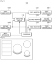
- FIG. 2 is a block diagram illustrating a configuration of a cooking apparatus according to an embodiment of the invention.
- a cooking apparatus 100 includes a switching circuit 110, a plurality of inverters 120-1, 120-2 and 120-3, a plurality of heating coils 130-1, 130-2 and 130-3, a plurality of power supplies 140-1 and 140-2, an input apparatus 150, and a processor 160.
- the input apparatus 150 acquires, from the user, a command to generate heat from one of the plurality of heating coils 130-1, 130-2 and 130-3.
- the command controls a heating coil to perform a turn-on/turn-off operation (i.e. pulse width modulation), or to select an output level and control a heating coil to be heated to the corresponding heating level.
- Such an output level may be in such a form that a directly corresponding value (for example, 1, 2, 3 or 4) is input or that a relative change value (for example, + 1 / - 1) is input.
- This input apparatus 150 may be implemented as a plurality of physical buttons or switches, etc., and may be implemented as a touch screen capable of simultaneously performing a display function displaying an operation state, etc.
- the processor 160 controls each element in the cooking apparatus.
- the processor 160 may, when a command for the respective heating coils is input through the input apparatus 150, control the switching circuit and the plurality of inverters so that a heating coil corresponding the command is operated.
- the processor 160 controls the plurality of inverters 120-1, 120-2 and 120-3 to supply a driving power based on the command provided to each of the plurality of heating coils 130-1, 130-2 and 130-3.
- the processor 160 may, when a command to request a heat amount of level "2" with respect to the first heating coil 130-1 is input, control the first inverter 120-1 to provide a first driving power corresponding to "2" to the first heating coil 130-1, and when a user command to request a heat amount of level "3" with respect to the second heating coil 130-2 is input, control the second inverter 120-2 to provide a second driving power corresponding to the second heating coil 130-2.
- the processor 160 may, when a command to request heat amount of level "1" with respect to the third heating coil 130-1 is input, control the third inverter 120-3 to provide a third driving power corresponding to "1" to the third heating coil 130-3.
- the processor 160 before controlling the switching circuit 110 to supply power to the plurality of inverters 120-1, 120-2 and 120-3, identifies a power supply to provide power to the plurality of inverters 120-1, 120-2 and 120-3 from among the plurality of power supplies 140-1 and 140-2.
- the processor 160 may calculate a power consumption of each of the plurality of heating coils 130-1, 130-2 and 130-3, and based on the power consumption, identify a power supply to be provided to the plurality of inverters 120-1, 120-2 and 120-3 from among the first power supply 140-1 or the second power supply 140-2.
- the processor 160 may, when a power consumption of the first heating coil 130-1 is 3 kW, a power consumption of the second heating coil 130-2 is 1.2 kW, and a power consumption of the third heating coil 130-3 is 0.8 kW, identify that the first power supply 140-1 is provided to the first inverter 120-1 and that the second power supply 140-2 is provided to both the second inverter 120-2 and the third inverter 120-3.
- the processor 160 may identify that the remaining power other than the power supplied to the first inverter 120-1 is supplied to the second inverter 120-2.
- the processor 160 compares a power consumed by the first heating coil 130-1 with a power consumed by the third heating coil 130-3 and identify which heating coil uses less power, and identify that a power supplied to an inverter corresponding to the corresponding heating coil is supplied to the second inverter 120-2 corresponding to the second heating coil 130-2.
- the processor 160 may identify that the second power supply 140-2 to supply power to the third heating coil 130-3, which is consuming less power (690 W) than is provided to the second inverter 120-2.
- the processor 160 may identify that the first power supply 140-1 to supply power to the first heating coil 130-1, which is consuming less power (690 W) than is provided to the second inverter 120-2.
- the processor 160 when a command of the first heating coil 130-1 or the third heating coil 130-3 is changed and a heating coil consuming less power is changed, identifies a power supply to provide power to an inverter corresponding to the changed heating coil is provided to the second inverter 120-2.
- the processor 160 may identify the second power supply 140-2 to supply the power to the third heating coil 130-3, which is consuming less power (2990 W) than is supplied to the second inverter 120-2.
- the processor 160 may, with respect to a command for the respective heating coils, rather than providing a fixed power supply to the inverters respectively corresponding to the heating coils and controlling a driving power supply corresponding to the use command to be supplied, identify that a plurality of power supplies are selectively provided to the respective inverters based on the command for the respective heating coils and a power consumption so that a required driving power is fully provided to each heating coil.
- the processor 160 may, when a power to be provided to the plurality of inverters 120-1, 120-2 and 120-3 is identified as described above, control the switching circuit 110 so that a power is provided to the plurality of inverters 120-1, 120-2 and 120-3 as identified.
- the switching circuit 110 may be controlled to provide the first power supply 140-1 to the first inverter 120-1 and the second inverter 120-2, and to provide the second power supply 140-2 to the third inverter 120-3.
- the processor 160 may, when the heating coil consuming less power described above is changed and a power to be provided to the second inverter 120-2 changes, control the switching circuit 110 to disconnect a previous power supply provided to the second inverter 120-2, and then to connect a power supply to the second inverter 120-2.
- the processor 160 may, when a power supply provided to the second inverter 120-2 is changed from the first power supply 140-1 to the second power supply 140-2, control the switching circuit 110 to disconnect the first power supply 140-1, and then to connect the second power supply 140-2 to the second inverter 120-2.
- the processor 160 may control the switching circuit 110 to disconnect a previous power supply provided to the second inverter 120-2, and then, after a preset time elapses, to connect a power supply to the second inverter 120-2.
- a preset time may correspond to a discharge time of a capacitor within an apparatus due to a switching operation, which may be identified based on experimentation.
- the processor 160 may control the switching circuit 110 disconnect the first power supply 140-1 from the second inverter 120-2, and after a time of approximately 15 ms elapses, connect the second power supply 140-2 to the second inverter 120-2.
- FIG. 2 two power supplies are input. However, in an example implementation, all three power supplies may be input and in this case, the processor 160 may identify that the three power supplies are dynamically provided to the respective inverters.
- the cooking apparatus 100 may further include a communication apparatus capable of being connected to a network via a wire or wirelessly according to a function supported by the cooking apparatus 100, and communicating with an external apparatus and the server, a memory capable of storing data and programs necessary for controlling the cooking apparatus 100, and the like.
- each heating coil uses a fixed power supply and thus, it is difficult to provide power supply efficiently when a plurality of burners are simultaneously used.
- first heating coil 130-1 and the second heating coil 130-2 are statically connected to the first power supply 140-1 and that the third heating coil 130-3 is statically connected to the second power supply 140-2
- the first power supply 140-1 is used when only the first heating coil 130-1 and the second heating coil 130-2 are simultaneously operated.
- the second power supply 140-2 cannot be used even though the second power supply 140-2 is present.
- the power supply cannot be efficiently used.
- the processor 160 may control the switching circuit 110 to selectively provide a power supply or to change a power supply to be provided, so that the power supply may be dynamically allocated.
- the processor 160 may control the switching circuit 110 to selectively provide a power supply or to change a power supply to be provided, so that the power supply may be dynamically allocated.
- FIG. 3 is a block diagram illustrating a configuration of a cooking apparatus according to an embodiment of the disclosure.
- a cooking apparatus 100' is provided to explain an example in which the first inverter 120-1 and the third inverter 120-3 fixedly use (i.e., statically connected to) the first power supply 140-1 and the second power supply 140-2, respectively, and the second inverter 120-2 selectively uses the first power supply 140-1 or the second power supply 140-2.
- the cooking apparatus 100' may include a switching circuit 110', a plurality of inverters 120-1, 120-2 and 120-3, a plurality of heating coils 130-1, 130-2 and 130-3, a plurality of power supplies 140-1 and 140-2, an input apparatus 150, and a processor 160.
- the switching circuit 110' may selectively connect the first power supply 140-1 or the second power supply 140-2 to the second inverter 120-2.
- the switching circuit 110' may selectively connect the first power supply 140-1 or the second power supply 140-2 to the second inverter 120-2 under the control of the processor 160.
- the switching circuit 110' may include two switches and may provide a power supply through an open and close operation of a switching switch.
- the switching circuit 110' may, when a switching circuit between the first power supply 140-1 and the second inverter 120-2 is closed and a switching circuit between the second power supply 140-2 and the second inverter 120-2 is opened, connect the first power supply 140-1 to the second inverter 120-2, and when the switching circuit between the second power supply 140-2 and the second inverter 120-2 is closed and the switching circuit between the first power supply 140-1 and the second inverter 140-2 is opened, connect the second power supply 140-2 to the second inverter 120-2.
- the switching circuit 110' may be disposed on one printed circuit substrate along with the second inverter 120-2. In addition, the switching circuit 110' may be disposed on a second substrate, which is spaced apart from a first substrate. Such a separation structure may flexibly cope with both a case of using the switching circuit 110' and a case of not using the switching circuit 110' when the cooking apparatus 100' is designed.
- the processor 160 may identify a power supply to be connected to the second inverter 120-2 because the first inverter 120-1 and the third inverter 120-3 are fixedly connected to the first power supply 140-1 and the second power supply 140-2.
- the processor 160 may identify a power supply to be connected to the second inverter 120-2 based on all operation states of the respective heating coils. That is, the processor 160 may identify a power supply to be connected to the second inverter 120-2 based on a power consumption of the plurality of heating coils 130-1, 130-2 and 130-3, an input command, etc.
- the processor 160 may calculate a power consumption of each of the plurality of heating coils 130-1, 130-2 and 130-3, and based on the power consumption, identify a power supply to be connected to the plurality of inverters 120-1, 120-2 and 120-3 from among the first power supply 140-1 or the second power supply 140-2.
- the processor 160 may identify that the second power supply 140-2 is connected to the second inverter 120-2.
- the processor 160 may identify that the first power supply 140-1 is connected to the second inverter 120-2.
- the example described above may correspond to a case in which the processor 160 compares a power consumed by the first heating coil 130-1 with a power consumed by the third heating coil 130-3 and identifies which heating coil uses less power, and identifies that a power supplied to an inverter corresponding to the corresponding heating coil is supplied to the second inverter 120-2 corresponding to the second heating coil 130-2.
- the processor 160 may identify that the first power supply 140-1 or the second power supply 140-2 is used according to a preset default value.
- the processor 160 may identify that a power supply connected to an inverter corresponding to the changed heating coil is supplied to the second inverter 120-2.
- the processor 160 may identify that the second power supply 140-2 supplies the power to the third heating coil 130-3, which is consuming less power (2990 W) than is supplied to the second inverter 120-2.
- the processor 160 may, when a power supply to be connected to the second inverter 120-2 is identified as described above, control the switching circuit 110' so that the power supply is connected to the second inverter 120-2. For example, when it is identified that the first power supply 140-1 is connected to and supplies power to the second inverter 120-2, the processor 160 may, control the switching circuit 110' to provide power from the first power supply 140-1 to the second inverter 120-2.
- the processor 160 may control the switching circuit 110' to turn off a previous power supply provided to the second inverter 120-2, and then to provide a power supply provided to an inverter corresponding to the changed heating coil to the second inverter 120-2.
- the processor 160 may control the switching circuit 110' to disconnect from the first power supply 140-1, and then connect the second power supply 140-2 to the second inverter 120-2.
- the processor 160 may control the switching circuit 110' to disconnect a previous power supply from the second inverter 120-2, and then, after a preset time elapses, connect a power supply to an inverter corresponding to the changed heating coil to the second inverter 120-2.
- a preset time may correspond to a discharge time of a capacitor within an apparatus due to a switching operation, which may be identified based on experimentation.
- the processor 160 may control the switching circuit 110' to disconnect the first power supply 140-1 from the second inverter 120-2, and after a time of approximately 15 ms elapses, to connect the second power supply 140-2 to the second inverter 120-2.
- two inverters acquire input of a fixed power supply.
- a single inverter may acquire input of a fixed power supply.
- FIG. 4 is a diagram illustrating an example cooking apparatus including a plurality of burners according to an embodiment of the disclosure.
- the cooking apparatus 100' may include three circular burners and a flexible burner including four areas.
- a heating operation may be performed for the entire area of the circular burner.
- a heating operation is performed only on an area of the flexible burner where a cooking container is seated.
- a heating operation is performed only on the three areas where the cooking container is located.
- the respective circular burners and the respective areas of the flexible burner of the cooking apparatus 100' may include one heating coil.
- the cooking apparatus 100' may include an inverter providing a driving power to a heating coil of the respective circular burners, and an inverter providing a driving power to two heating coils of the flexible burner. An explanation of the heating coil will be discussed below with reference to FIG. 5 .
- the cooking apparatus 100' may include three inverters corresponding to the three circular burners, and two inverters corresponding to the flexible burner, and thus, a total of five inverters.
- FIG. 5 is a circuit diagram of the example cooking apparatus in FIG. 4 according to an embodiment of the disclosure.
- the cooking apparatus 100' may include three printed circuit boards (PBAs) 520-1, 520-2 and 520-3, a plurality of power supplies 140-1 and 140-2, and a switching circuit 110'.
- PBAs printed circuit boards
- the respective PBAs 520-1, 520-2 and 520-3 may include a bridge diode 540-1, 540-2 and 540-3 to rectify an input power source (i.e., convert alternating current to direct current), and inverters 510-1, 510-2, 510-3, 510-4 and 510-5.
- the PBA 1 520-1 may include a first inverter 530-1 and a second inverter 530-2.
- the PBA 2 520-2 may include a third inverter 530-3.
- the PBA 3 520-3 may include a fourth inverter 530-4 and a fifth inverter 530-5.
- the first inverter 530-1 may provide a driving power to two heating coils 510-1 and 510-2
- the second inverter 530-2 may provide a driving power to two heating coils 510-3 and 510-4
- the third inverter 530-3 may provide a driving power to one heating coil 510-5
- the fourth inverter 530-4 may provide a driving power to one heating coil 510-6
- the fifth inverter 530-5 may provide a driving power to one heating coil 510-7.
- the PBA 1 520-1 may acquire a fixed power supply from the second power supply 140-2.
- the PBA 3 520-3 may acquire a fixed power supply from the first power supply 140-1.
- PBA 2 520-2 may selectively acquire a power supply from the first power supply 140-1 or the second power supply 140-2 via the switching circuit 110'.
- the respective inverters 530-1, 530-2, 530-3, 530-4 and 530-5 may provide a driving power to a corresponding heating coil by using a power supply provided to a PBA.
- the switching circuit 110' may include switches 110'-1 and 110'-2, which are disposed between a voltage line L of the plurality of power supplies 140-1 and 140-2 and one terminal of the PBA 2 520-2.
- the switching circuit 110' may include switches 110'-3 and 110'-4, which are disposed between a neutral line N of the plurality of power supplies 140-1 and 140-2 and one terminal of the PBA 2 520-2.
- the switching circuit 110' may perform a switching operation using the switches 110'-1 and 110'-2 connected to the voltage line L and the switches 110'-3 and 110'-4 connected to the neutral line N.
- the first power supply 140-1 may be connected to the PBA 2 520-2.
- the second power supply 140-2 may be connected to the PBA 2 520-2.
- the switching circuit 110' may, rather than including the switches 110'-3 and 110'-4 in the neutral line N, connect one terminal of the PBA 2 520-2 to the neutral line N, and perform a switching operation using the switches 110'-1 and 110'-2.
- the first power supply 140-1 may be connected to the PBA 2 520-2.
- the second power supply 140-2 may be connected to the PBA 2 520-2.
- the respective PBAs 520-1, 520-2 and 520-3 may include a rectifier circuit to rectify a power input to the respective PBAs, a smoothing circuit to substantially convert the rectified power supply to a direct current, and an inverter providing a driving power of a preset frequency using the direct current.
- the rectifier circuit may include bridge diodes 540-1, 540-2 and 540-3, and the respective bridge diodes 540-1, 540-2 and 540-3 may correspond to a bridge diode of a bidirectional relay type.
- the switching circuit 110' is a first substrate including the third inverter 530-3, which is disposed on a separate second substrate and spaced apart from the PBA 2 520-2. However, the switching circuit 110' is combined into the PBA 2 520-2.
- a structure as in the switching circuit 110' of FIG. 5 may flexibly cope with both a case of using the switching circuit 110' and a case of not using the switching circuit 110' when the cooking apparatus 100' is designed.
- FIG. 6 is another circuit diagram of the example cooking apparatus in FIG. 4 according to an embodiment of the disclosure.
- a circuit configuration of the cooking apparatus 100' may include a plurality of fan motors 610-1 and 610-2, an electromagnetic interference (EMI) filter 620, a switching mode power supply (SMPS) 630, a plurality of PBAs 520-1, 520-2 and 520-3, and a plurality of switches 110'-1, 110'-2, 110'-3 and 110'-4.
- EMI electromagnetic interference
- SMPS switching mode power supply
- the fan motor 610-1 and 610-2 may perform cooling of a heat sink (not illustrated) that is attached to at least one of PBAs 520-1, 520-2 and 520-3.
- the SMPS 630 may convert one of the first power supply or the second power supply into a direct current (DC) power supply.
- the EMI filter 620 may include a transformer and a capacitor and may remove noise mixed in a power supplied from the plurality of power supplies 140-1 and 140-2.
- the two power supplies 140-1 and 140-2 input to the EMI filter 620 may be connected to supply power to the respective PBAs.
- the PBA 1 520-1 may acquire a fixed power from the second power supply 140-2.
- the PBA 3 may acquire a fixed power from the first power supply 140-1.
- the PBA 2 may selectively acquire power from the first power supply 140-1 or the second power supply 140-2 via the switching circuit 110'.
- fan motors 610-1 and 610-2 are included. However, in an example embodiment, a single fan may be included three or more fan motors may be provided.
- the switching circuit 110' is combined into the PBA 2 520-2.
- the switching circuit 110' may be disposed on a first substrate including the third inverter 530-3 and spaced apart from the PBA 2 520-2.
- FIG. 7 is a flowchart illustrating a method for controlling of a cooking apparatus according to an embodiment of the invention.
- a cooking apparatus acquires input of a plurality of power supplies of different phases.
- a power supply is identified to be connected to a plurality of inverters individually providing a driving power to each of a plurality of heating coils at operation S710.
- a method for identifying a power supply to be provided to the plurality of inverters may be a method of identifying from among a first power supply or a second power supply based on a power consumption of each of the plurality of heating coils.
- a power consumption of the first heating coil is 3 kW
- a power consumption of the second heating coil is 1.2 kW
- a power consumption of the third heating coil is 0.8 kW
- a command for each of the plurality of heating coils is acquired, and then, a power supply to be connected to each of the plurality of inverters is identified so that a driving power may be provided to each of the plurality of heating coils.
- a command requires a strong output with respect to the first heating coil
- a command requires an intermediate output with respect to the second heating coil
- a command requires a small output with respect to the third heating coil.
- the first power supply is connected to the first heating coil
- the second power supply is connected to both the second heating coil and the third heating coil.
- a method identifies a power supply to be connected to the plurality of inverters, identifies when a use command of the second heating coil is input while the first power supply is provided to the first inverter corresponding to the first heating coil from among the plurality of heating coils, and connects the second power supply to the second inverter corresponding to the second heating coil.
- the second power supply which is not currently providing power, is connected to the second heating coil to supply drive power.
- a method identifies that, while the first power supply is connected to the first inverter corresponding to the first heating coil and the second power supply is connected to the second inverter corresponding to the second heating coil, when a use command of the third heating coil is input, a power supply connected to an inverter corresponding to a heating coil consuming a lower power consumption amount from coil is provided to the third inverter corresponding to the third heating coil.
- the second power supply supplies power to the second heating coil, which is consuming less power (690 W) than is provided to the third inverter.
- the method identify that a power supply connected to an inverter corresponding to the changed heating coil.
- the second power supply supplies the power to the second heating coil, which is consuming less power (2990 W) than is provided to the third inverter.
- the identified power supply may be provided to each of the plurality of inverters, at operation S720.
- a method for providing a power supply identified when the heating coil consuming less power described above is changed disconnects a previous power supply from to the third inverter, and then connects a power supply to the third inverter corresponding to the changed heating coil.
- the previous power supply is disconnected from the third inverter, and after a preset time elapses, the power supply is provided to the third inverter corresponding to the changed heating coil.
- the preset time may be 15 ms, as described above with reference to FIG. 3 .
- a driving power may be generated and provided to each of the plurality of inverters, at operation S730.
- the respective inverters may provide a driving power necessary to heat the corresponding heating coil.
- the first inverter may provide a first driving power supply to the corresponding first heating coil
- the second inverter may provide a second driving power supply to the corresponding second heating coil
- a power consumption amount necessary for the respective heating coils may be identified and a power supply is selectively provided to at least one heating coil by using a switching circuit, so that a cooking function may be improved despite the limited power supply.
- the method for controlling of FIG. 7 may be performed on the cooking apparatus including the constitution of FIG. 1, 2 or 4 , or performed on another cooking apparatus including different constitution.
- the above-described method for controlling may be realized as at least one execution program to execute the above-described controlling method, and such an execution program may be stored in a non-transitory computer readable medium.
- a non-transitory computer readable medium may refer to a machine-readable medium or device that stores data semi-permanently and not for a short period of time, such as a register, cache, memory, and the like.
- a non-transitory readable medium such as a compact disc (CD), digital versatile disc (DVD), hard disk, Blu-ray disk, universal serial bus (USB) storage medium, memory card, and a read only memory (ROM) and provided therein.
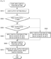
- FIG. 8 is a flowchart provided to explain in further detail a power supply identification operation of FIG. 7 according to an embodiment of the disclosure.
- FIG. 8 it may be assumed that an aspect of the method for controlling is a cooking apparatus 100' provided with three PBAs 520-1, 520-2 and 520-3.
- FIG. 8 may explain which power supply is to be used when the PBA 2 520-2 is operated while the PBA 1 520-1 and the PBA 3 520-3 are operated.
- the PBA 1 520-1 acquires a fixed power supply from the second power supply 140-2
- the PBA 3 520-3 acquires a fixed power supply from the first power supply 140-1.
- a command for each heating coil may be identified at operation S810.
- a use command such as an output level with respect to the respective heating coils 510-1 to 510-7, and the like may be input from the user via the input apparatus 150.
- the PBA 3 520-3 acquires a fixed power supply from the first power supply and thus, when the PBA 2 520-2 is not operated, a power consumption of the PBA 3 520-3 may be calculated as an estimated power of the first power supply.
- a switch position may be set to ON with respect to the switches 110'-1 and 110'-3 connected to the first power supply, and to OFF with respect to the switches 110'-2 and 110'-4 with respect to the second power supply.
- 3.6 kW may correspond to identification criteria for selecting a power supply when a power consumption of each of a plurality of power supplies to provide an appropriate power supply from among the plurality of power supplies to a heating coil, and various values other than 3.6 kW may be used as identification criteria according to an implementation method of the cooking apparatus 100'.
- a switch position may be set to ON with respect to the switches 110'-1 and 110'-3, and to OFF with respect to the switches 110'-2 and 110'-4.
- the PBA 1 520-1 acquires a fixed power supply from the second power supply and thus, when the PBA 2 520-2 is not operated, a power consumption of the PBA 1 520-1 may be calculated as an output of the second power supply.
- a switch position may be set to ON with respect to the switches 110'-1 and 110'-3 connected to the first power supply, and to OFF with respect to the switches 110'-2 and 110'-4 with respect to the second power supply, at operation S850.
- a power is provided to the PBA 2 520-2 from the first power supply and thus, a switch position may be set to ON with respect to the switches 110'-1 and 110'-3, and to OFF with respect to the switches 110'-2 and 110'-4.
- a switch position may be set to OFF with respect to the switches 110'-1 and 110'-3, and to ON with respect to the switches 110'-2 and 110'-4, at operation S840.
- a power is supplied to the PBA 2 520-2 from the second power supply and thus, a switch position may be set to OFF with respect to the switches 110'-1 and 110'-3, and to ON with respect to the switches 110'-2 and 110'-4.
- a switch position setting may be completed by the switching operation, at operation S860, and an actual output for each burner may be finalized based on the switch position, at operation S870.
- a power consumption amount necessary for already-operating heating coils may be identified and a power supply is selectively provided to at least one heating coil by using a switching circuit, so that a cooking function may be improved despite the limited power supply.
- the method for controlling of FIG. 8 may be performed on the cooking apparatus including the constitution of FIGS. 1, 2 or 4 , or performed on another cooking apparatus including different constitution.
- the above-described method for controlling may be realized as at least one execution program to execute the above-described controlling method, and such an execution program may be stored in a non-transitory computer readable medium.
Landscapes
- Physics & Mathematics (AREA)
- Electromagnetism (AREA)
- Induction Heating Cooking Devices (AREA)
Claims (8)
- Kochvorrichtung, die Eingang von einer Vielzahl von Stromversorgungen von unterschiedlichen Phasen erhält, wobei die Kochvorrichtung Folgendes umfasst:die Vielzahl von Stromversorgungen, beinhaltend eine erste Stromversorgung (140-1) und eine zweite Stromversorgung (140-2);eine Vielzahl von Heizspulen, beinhaltend eine erste Heizspule (130-1), eine zweite Heizspule (130-2) und eine dritte Heizspule (130-3);eine Vielzahl von Wechselrichtern, beinhaltend einen ersten Wechselrichter (120-1), einen zweiten Wechselrichter (120-2) und einen dritten Wechselrichter (120-3);einen Schaltkreis (110, 110'), der konfiguriert ist, um selektiv Strom von der ersten Stromversorgung (140-1) oder der zweiten Stromversorgung (140-2) an zumindest einen von dem ersten Wechselrichter (120-1), dem zweiten Wechselrichter (102-2) oder dem dritten Wechselrichter (120-3) bereitzustellen;eine Eingangsvorrichtung (150), die konfiguriert ist, um einen ersten Befehl zum Betrieb der ersten Heizspule (130-1), einen zweiten Befehl zum Betrieb der zweiten Heizspule (130-2) und einen dritten Befehl zum Betrieb der dritten Heizspule (130-3) zu empfangen; undeinen Prozessor (160), der zu Folgendem konfiguriert ist:Steuern des Schaltkreises (110, 110'), um die erste Stromversorgung (140-1) mit dem ersten Wechselrichter (120-1) zu verbinden, und Steuern des ersten Wechselrichters (120-1), um einen ersten Antriebsstrom an die erste Heizspule (130-1) auszugeben, wenn der erste Befehl empfangen wird, undSteuern des Schaltkreises (110, 110'), um die zweite Stromversorgung (140-2) mit dem zweiten Wechselrichter (120-2) zu verbinden, und Steuern des zweiten Wechselrichters (120-2), um einen zweiten Antriebsstrom an die zweite Heizspule (130-2) auszugeben, wenn der zweite Befehl empfangen wird, undSteuern des dritten Wechselrichters (120-3), um einen dritten Antriebsstrom an die dritte Heizspule (130-3) auszugeben, wenn der dritte Befehl empfangen wird,wobei der Prozessor (160) ferner konfiguriert ist, um, wenn der dritte Befehl empfangen wird, zu identifizieren, dass die erste Heizspule (130-1) weniger Strom als die zweite Heizspule (130-2) verbraucht, und Steuern des Schaltkreises (110, 110'), um die erste Stromversorgung (140-1) mit dem dritten Wechselrichter (120-3) zu verbinden, undwobei der Prozessor (160) ferner konfiguriert ist, um als Reaktion auf einen Befehl zum Ändern von Strom, der durch die erste Heizspule (130-1) oder die zweite Heizspule (130-2) verbraucht wird, zu identifizieren, dass die erste Heizspule (130-1) mehr Strom als die zweite Heizspule (130-2) verbraucht, und Steuern des Schaltkreises (110, 110'), um die erste Stromversorgung (140-1) von dem dritten Wechselrichter (120-3) zu trennen und, nachdem eine voreingestellte Zeit abläuft, die zweite Stromversorgung (140-2) mit dem dritten Wechselrichter (120-3) zu verbinden.
- Kochvorrichtung nach Anspruch 1, wobei der Prozessor (160) konfiguriert ist, um basierend auf einem ersten Stromverbrauch der ersten Heizspule (130-1) und einem zweiten Stromverbrauch der zweiten Heizspule (130-2) zu identifizieren, ob die erste Stromversorgung (140-1) oder die zweite Stromversorgung (140-2) dem ersten Wechselrichter (120-1) oder dem zweiten Wechselrichter (120-2) bereitgestellt ist.
- Kochvorrichtung nach Anspruch 1, wobei der Prozessor (160) ferner konfiguriert ist, um basierend auf dem Empfang des zweiten Befehls der zweiten Heizspule (130-2), während die erste Stromversorgung (140-1) mit dem ersten Wechselrichter (120-1) verbunden ist, den Schaltkreis (110, 110') zu steuern, um die zweite Stromversorgung (140-2) mit dem zweiten Wechselrichter (120-2) zu verbinden.
- Kochvorrichtung nach Anspruch 1, wobei der erste Wechselrichter (120-1) konfiguriert ist, um Antriebsstrom an die erste Heizspule (130-1) basierend auf nur der ersten Stromversorgung (140-1) bereitzustellen,wobei der zweite Wechselrichter (120-2) konfiguriert ist, um Antriebsstrom an die zweite Heizspule (130-2) basierend auf der ersten Stromversorgung oder der zweiten Stromversorgung (140-2) bereitzustellen,wobei der dritte Wechselrichter (120-3) konfiguriert ist, um Antriebsstrom an die dritte Heizspule (130-3) basierend auf nur der zweiten Stromversorgung bereitzustellen, undwobei der Schaltkreis (110') konfiguriert ist, um selektiv die erste Stromversorgung oder die zweite Stromversorgung mit dem zweiten Wechselrichter zu verbinden.
- Kochvorrichtung nach Anspruch 4, wobei der Schaltkreis (110') Folgendes umfasst:einen ersten Schalter, der konfiguriert ist, um einen Ausgangsanschluss der ersten Stromversorgung (140-1) oder einen Ausgangsanschluss der zweiten Stromversorgung (140-2) mit einem Eingangsanschluss des zweiten Wechselrichters (120-2) zu verbinden; undeinen zweiten Schalter, der konfiguriert ist, um einen anderen Ausgangsanschluss der ersten Stromversorgung oder einen anderen Ausgangsanschluss der zweiten Stromversorgung mit einem anderen Eingangsanschluss des zweiten Wechselrichters zu verbinden.
- Verfahren zum Steuern einer Kochvorrichtung, die Eingang von einer Vielzahl von Stromversorgungen von unterschiedlichen Phasen erhält, wobei das Verfahren Folgendes umfasst:Identifizieren von Strom, der durch die Vielzahl von Stromversorgungen, beinhaltend eine erste Stromversorgung (140-1) und eine zweite Stromversorgung (140-2), an eine Vielzahl von Wechselrichtern, beinhaltend einen ersten Wechselrichter (120-1), einen zweiten Wechselrichter (120-2) und einen dritten Wechselrichter (120-3), bereitzustellen ist, wobei jeder aus der Vielzahl von Wechselrichtern (120) einzeln einen Antriebsstrom an eine entsprechende erste Heizspule (130-1), zweite Heizspule (130-2) und dritte Heizspule (130-3) aus einer Vielzahl von Heizspulen (130) bereitstellt;selektives Bereitstellen des Stroms von der ersten Stromversorgung (140-1) oder der zweiten Stromversorgung (140-2) an zumindest einen von dem ersten Wechselrichter (120-1), dem zweiten Wechselrichter (120-2) oder dem dritten Wechselrichter (120-3);Erzeugen des Antriebsstroms für jeden aus der Vielzahl von Wechselrichtern (120); undBereitstellen des Antriebsstroms an jede aus der Vielzahl von Heizspulen (130),wobei das Verfahren ferner Folgendes umfasst:wenn ein erster Befehl empfangen wird, Verbinden der ersten Stromversorgung (140-1) mit dem ersten Wechselrichter (120-1), Ausgeben eines ersten Antriebsstroms an die erste Heizspule (130-1),wenn ein zweiter Befehl empfangen wird, Verbinden der zweiten Stromversorgung (140-2) mit dem zweiten Wechselrichter (120-2), Ausgeben eines zweiten Antriebsstroms an die zweite Heizspule (130-2), undwenn ein dritter Befehl empfangen wird, Ausgeben eines dritten Antriebsstroms an die dritte Heizspule (130-3),wobei das Verfahren ferner Folgendes umfasst:wenn der dritte Befehl empfangen wird, Identifizieren, dass die erste Heizspule (130-1) weniger Strom als die zweite Heizspule (130-2) verbraucht, und Verbinden der ersten Stromversorgung (140-1) mit dem dritten Wechselrichter (120-3), undals Reaktion auf einen Befehl zum Ändern von Strom, der durch die erste Heizspule (130-1) oder die zweite Heizspule (130-2) verbraucht wird, Identifizieren, dass die erste Heizspule (130-1) mehr Strom als die zweite Heizspule (130-2) verbraucht, Trennen der ersten Stromversorgung (140-1) von dem dritten Wechselrichter (120-3) und, nachdem eine voreingestellte Zeit abläuft, Verbinden der zweiten Stromversorgung (140-2) mit dem dritten Wechselrichter (120-3).
- Verfahren nach Anspruch 6, wobei das Identifizieren des Stroms Identifizieren umfasst, ob die erste Stromversorgung (140-1) oder die zweite Stromversorgung (140-2) dem ersten Wechselrichter (120-1) oder dem zweiten Wechselrichter (120-2) bereitgestellt wird, basierend auf einem ersten Stromverbrauch der ersten Heizspule (130-1) und einem zweiten Stromverbrauch der zweiten Heizspule (130-2).
- Verfahren nach Anspruch 6, wobei das Identifizieren des Stroms basierend auf dem Empfang des zweiten Befehls der zweiten Heizspule (130-2), während die erste Stromversorgung (140-1) mit dem ersten Wechselrichter (120-1) verbunden ist, Verbinden der zweiten Stromversorgung (140-2) mit dem zweiten Wechselrichter (120-2) umfasst.
Applications Claiming Priority (2)
| Application Number | Priority Date | Filing Date | Title |
|---|---|---|---|
| KR1020180072983A KR102541269B1 (ko) | 2018-06-25 | 2018-06-25 | 조리 기기 및 이의 제어 방법 |
| PCT/KR2019/007632 WO2020004892A1 (en) | 2018-06-25 | 2019-06-25 | Cooking apparatus and method for controlling thereof |
Publications (3)
| Publication Number | Publication Date |
|---|---|
| EP3777477A1 EP3777477A1 (de) | 2021-02-17 |
| EP3777477A4 EP3777477A4 (de) | 2021-05-19 |
| EP3777477B1 true EP3777477B1 (de) | 2024-09-25 |
Family
ID=68980849
Family Applications (1)
| Application Number | Title | Priority Date | Filing Date |
|---|---|---|---|
| EP19826298.2A Active EP3777477B1 (de) | 2018-06-25 | 2019-06-25 | Kochvorrichtung und verfahren zur steuerung davon |
Country Status (5)
| Country | Link |
|---|---|
| US (1) | US11612020B2 (de) |
| EP (1) | EP3777477B1 (de) |
| KR (1) | KR102541269B1 (de) |
| CN (1) | CN112385311B (de) |
| WO (1) | WO2020004892A1 (de) |
Families Citing this family (5)
| Publication number | Priority date | Publication date | Assignee | Title |
|---|---|---|---|---|
| US20230328852A1 (en) * | 2020-09-02 | 2023-10-12 | BSH Hausgeräte GmbH | Domestic appliance device and method for operating a domestic appliance device |
| JP7594414B2 (ja) * | 2020-11-20 | 2024-12-04 | キヤノン株式会社 | 電力供給装置、システム、露光装置および物品製造方法 |
| EP4170241A1 (de) * | 2021-10-25 | 2023-04-26 | Electrolux Appliances Aktiebolag | Steuervorrichtung für ein kochfeld und kochfeld mit einer steuervorrichtung |
| KR20230080215A (ko) * | 2021-11-29 | 2023-06-07 | 삼성전자주식회사 | 다중 전원 구조를 갖는 조리기기 |
| KR20250075367A (ko) * | 2023-11-21 | 2025-05-28 | 삼성전자주식회사 | 유도 가열 장치 및 그 제어 방법 |
Family Cites Families (15)
| Publication number | Priority date | Publication date | Assignee | Title |
|---|---|---|---|---|
| JP4301083B2 (ja) | 2004-05-28 | 2009-07-22 | パナソニック株式会社 | 誘導加熱調理器 |
| ES2300168B1 (es) | 2005-10-27 | 2009-05-08 | Bsh Electrodomesticos España, S.A. | Encimera de cocina y procedimiento para el funcionamiento de una encimera de cocina. |
| KR100740336B1 (ko) | 2006-04-14 | 2007-07-19 | 주식회사 피에스텍 | 무정지형 유도가열 전원장치 및 그를 제어하기 위한 방법 |
| ES2352772B1 (es) | 2008-12-19 | 2012-01-26 | Bsh Electrodomésticos España, S.A. | Campo de cocción con varios elementos de calentamiento y al menos un grupo constructivo de la electrónica de potencia. |
| CN101909375B (zh) | 2009-06-08 | 2012-11-28 | 深圳市鑫汇科科技有限公司 | 基于SoC芯片的大功率电磁炉电路 |
| KR20110092891A (ko) | 2010-02-10 | 2011-08-18 | 삼성전자주식회사 | 유도가열조리기 |
| KR101492068B1 (ko) * | 2010-08-05 | 2015-02-10 | 삼성전자 주식회사 | 유도가열조리기 및 그 제어방법 |
| DE102012201237A1 (de) | 2011-02-25 | 2012-08-30 | BSH Bosch und Siemens Hausgeräte GmbH | Hausgerätevorrichtung |
| ES2441647B1 (es) | 2011-12-05 | 2014-12-04 | Bsh Electrodomésticos España, S.A. | Dispositivo de calentamiento por inducción con una unidad de mando |
| EP2888925B1 (de) | 2012-08-27 | 2018-02-21 | BSH Bosch und Siemens Hausgeräte GmbH | Hausgerätevorrichtung |
| JP5734390B2 (ja) | 2013-10-29 | 2015-06-17 | 三菱電機株式会社 | 誘導加熱調理器 |
| EP2869445A1 (de) | 2013-11-01 | 2015-05-06 | DET International Holding Limited | Anpassbare Gleichrichteranordnung für Betrieb an verschiedenen AC Netzen |
| KR20160006308A (ko) | 2014-07-08 | 2016-01-19 | 주식회사 크로마아이티 | Scr 정류 회로의 역률 개선 제어 장치 |
| US10455647B2 (en) * | 2014-11-26 | 2019-10-22 | Samsung Electronics Co., Ltd. | Cooking apparatus and method for controlling the same |
| KR102629987B1 (ko) | 2016-09-01 | 2024-01-29 | 삼성전자주식회사 | 조리 장치 및 그 제어 방법 |
-
2018
- 2018-06-25 KR KR1020180072983A patent/KR102541269B1/ko active Active
-
2019
- 2019-06-24 US US16/450,318 patent/US11612020B2/en active Active
- 2019-06-25 CN CN201980043326.3A patent/CN112385311B/zh active Active
- 2019-06-25 EP EP19826298.2A patent/EP3777477B1/de active Active
- 2019-06-25 WO PCT/KR2019/007632 patent/WO2020004892A1/en not_active Ceased
Also Published As
| Publication number | Publication date |
|---|---|
| KR102541269B1 (ko) | 2023-06-09 |
| US20190394837A1 (en) | 2019-12-26 |
| KR20200000751A (ko) | 2020-01-03 |
| EP3777477A4 (de) | 2021-05-19 |
| EP3777477A1 (de) | 2021-02-17 |
| CN112385311B (zh) | 2023-07-14 |
| WO2020004892A1 (en) | 2020-01-02 |
| CN112385311A (zh) | 2021-02-19 |
| US11612020B2 (en) | 2023-03-21 |
Similar Documents
| Publication | Publication Date | Title |
|---|---|---|
| CN112385311B (zh) | 烹饪装置及其控制方法 | |
| EP3852492B1 (de) | Kochvorrichtung und steuerungsverfahren dafür | |
| US20110253706A1 (en) | Heating device with plural induction coils | |
| KR102082507B1 (ko) | 제어 알고리즘 및 회로 구조가 개선된 유도 가열 장치 | |
| JP5642289B2 (ja) | 誘導加熱調理器 | |
| EP3310128A1 (de) | Induktionsheizvorrichtung und steuerungsverfahren dafür | |
| JP5958715B2 (ja) | 誘導加熱装置 | |
| JP5031005B2 (ja) | 誘導加熱装置及び誘導加熱調理器 | |
| JP4325446B2 (ja) | 誘導加熱装置 | |
| JP4431346B2 (ja) | 誘導加熱調理器 | |
| JP5340026B2 (ja) | 誘導加熱調理器 | |
| KR102903205B1 (ko) | 유도 가열 조리기기의 소음 제거 시스템 및 방법 | |
| JP6076040B2 (ja) | 誘導加熱調理器 | |
| JPWO2017081859A1 (ja) | 誘導加熱調理器 | |
| CN210183583U (zh) | 加热控制电路及电磁炉 | |
| EP4106490A1 (de) | Induktionskochvorrichtung | |
| KR20240024728A (ko) | 유도가열장치 및 유도가열장치의 제어방법 | |
| CN117480859A (zh) | 感应烹饪器具 | |
| JP2007073409A (ja) | 誘導加熱調理器 | |
| KR20210088841A (ko) | 유도 가열 장치 및 이에 포함되는 가열 코일 구동 회로 | |
| JP2011100568A (ja) | 誘導加熱調理器 | |
| JP2008021433A (ja) | 加熱調理器 | |
| HK1190560B (en) | Induction heating device | |
| HK1186903B (en) | Induction heating cooker | |
| JP2010153168A (ja) | 誘導加熱調理器 |
Legal Events
| Date | Code | Title | Description |
|---|---|---|---|
| STAA | Information on the status of an ep patent application or granted ep patent |
Free format text: STATUS: THE INTERNATIONAL PUBLICATION HAS BEEN MADE |
|
| PUAI | Public reference made under article 153(3) epc to a published international application that has entered the european phase |
Free format text: ORIGINAL CODE: 0009012 |
|
| STAA | Information on the status of an ep patent application or granted ep patent |
Free format text: STATUS: REQUEST FOR EXAMINATION WAS MADE |
|
| 17P | Request for examination filed |
Effective date: 20201028 |
|
| AK | Designated contracting states |
Kind code of ref document: A1 Designated state(s): AL AT BE BG CH CY CZ DE DK EE ES FI FR GB GR HR HU IE IS IT LI LT LU LV MC MK MT NL NO PL PT RO RS SE SI SK SM TR |
|
| AX | Request for extension of the european patent |
Extension state: BA ME |
|
| A4 | Supplementary search report drawn up and despatched |
Effective date: 20210419 |
|
| RIC1 | Information provided on ipc code assigned before grant |
Ipc: H05B 6/06 20060101AFI20210413BHEP Ipc: H05B 6/04 20060101ALI20210413BHEP Ipc: H05B 6/12 20060101ALI20210413BHEP |
|
| DAV | Request for validation of the european patent (deleted) | ||
| DAX | Request for extension of the european patent (deleted) | ||
| STAA | Information on the status of an ep patent application or granted ep patent |
Free format text: STATUS: EXAMINATION IS IN PROGRESS |
|
| 17Q | First examination report despatched |
Effective date: 20231012 |
|
| GRAP | Despatch of communication of intention to grant a patent |
Free format text: ORIGINAL CODE: EPIDOSNIGR1 |
|
| STAA | Information on the status of an ep patent application or granted ep patent |
Free format text: STATUS: GRANT OF PATENT IS INTENDED |
|
| GRAS | Grant fee paid |
Free format text: ORIGINAL CODE: EPIDOSNIGR3 |
|
| GRAA | (expected) grant |
Free format text: ORIGINAL CODE: 0009210 |
|
| STAA | Information on the status of an ep patent application or granted ep patent |
Free format text: STATUS: THE PATENT HAS BEEN GRANTED |
|
| INTG | Intention to grant announced |
Effective date: 20240802 |
|
| AK | Designated contracting states |
Kind code of ref document: B1 Designated state(s): AL AT BE BG CH CY CZ DE DK EE ES FI FR GB GR HR HU IE IS IT LI LT LU LV MC MK MT NL NO PL PT RO RS SE SI SK SM TR |
|
| REG | Reference to a national code |
Ref country code: GB Ref legal event code: FG4D |
|
| REG | Reference to a national code |
Ref country code: CH Ref legal event code: EP |
|
| REG | Reference to a national code |
Ref country code: DE Ref legal event code: R096 Ref document number: 602019059511 Country of ref document: DE |
|
| REG | Reference to a national code |
Ref country code: IE Ref legal event code: FG4D |
|
| REG | Reference to a national code |
Ref country code: LT Ref legal event code: MG9D |
|
| PG25 | Lapsed in a contracting state [announced via postgrant information from national office to epo] |
Ref country code: NO Free format text: LAPSE BECAUSE OF FAILURE TO SUBMIT A TRANSLATION OF THE DESCRIPTION OR TO PAY THE FEE WITHIN THE PRESCRIBED TIME-LIMIT Effective date: 20241225 |
|
| PG25 | Lapsed in a contracting state [announced via postgrant information from national office to epo] |
Ref country code: GR Free format text: LAPSE BECAUSE OF FAILURE TO SUBMIT A TRANSLATION OF THE DESCRIPTION OR TO PAY THE FEE WITHIN THE PRESCRIBED TIME-LIMIT Effective date: 20241226 Ref country code: FI Free format text: LAPSE BECAUSE OF FAILURE TO SUBMIT A TRANSLATION OF THE DESCRIPTION OR TO PAY THE FEE WITHIN THE PRESCRIBED TIME-LIMIT Effective date: 20240925 |
|
| PG25 | Lapsed in a contracting state [announced via postgrant information from national office to epo] |
Ref country code: BG Free format text: LAPSE BECAUSE OF FAILURE TO SUBMIT A TRANSLATION OF THE DESCRIPTION OR TO PAY THE FEE WITHIN THE PRESCRIBED TIME-LIMIT Effective date: 20240925 |
|
| PG25 | Lapsed in a contracting state [announced via postgrant information from national office to epo] |
Ref country code: LV Free format text: LAPSE BECAUSE OF FAILURE TO SUBMIT A TRANSLATION OF THE DESCRIPTION OR TO PAY THE FEE WITHIN THE PRESCRIBED TIME-LIMIT Effective date: 20240925 |
|
| PG25 | Lapsed in a contracting state [announced via postgrant information from national office to epo] |
Ref country code: RS Free format text: LAPSE BECAUSE OF FAILURE TO SUBMIT A TRANSLATION OF THE DESCRIPTION OR TO PAY THE FEE WITHIN THE PRESCRIBED TIME-LIMIT Effective date: 20241225 |
|
| REG | Reference to a national code |
Ref country code: NL Ref legal event code: MP Effective date: 20240925 |
|
| PG25 | Lapsed in a contracting state [announced via postgrant information from national office to epo] |
Ref country code: RS Free format text: LAPSE BECAUSE OF FAILURE TO SUBMIT A TRANSLATION OF THE DESCRIPTION OR TO PAY THE FEE WITHIN THE PRESCRIBED TIME-LIMIT Effective date: 20241225 Ref country code: NO Free format text: LAPSE BECAUSE OF FAILURE TO SUBMIT A TRANSLATION OF THE DESCRIPTION OR TO PAY THE FEE WITHIN THE PRESCRIBED TIME-LIMIT Effective date: 20241225 Ref country code: LV Free format text: LAPSE BECAUSE OF FAILURE TO SUBMIT A TRANSLATION OF THE DESCRIPTION OR TO PAY THE FEE WITHIN THE PRESCRIBED TIME-LIMIT Effective date: 20240925 Ref country code: GR Free format text: LAPSE BECAUSE OF FAILURE TO SUBMIT A TRANSLATION OF THE DESCRIPTION OR TO PAY THE FEE WITHIN THE PRESCRIBED TIME-LIMIT Effective date: 20241226 Ref country code: FI Free format text: LAPSE BECAUSE OF FAILURE TO SUBMIT A TRANSLATION OF THE DESCRIPTION OR TO PAY THE FEE WITHIN THE PRESCRIBED TIME-LIMIT Effective date: 20240925 Ref country code: BG Free format text: LAPSE BECAUSE OF FAILURE TO SUBMIT A TRANSLATION OF THE DESCRIPTION OR TO PAY THE FEE WITHIN THE PRESCRIBED TIME-LIMIT Effective date: 20240925 |
|
| REG | Reference to a national code |
Ref country code: AT Ref legal event code: MK05 Ref document number: 1727740 Country of ref document: AT Kind code of ref document: T Effective date: 20240925 |
|
| PG25 | Lapsed in a contracting state [announced via postgrant information from national office to epo] |
Ref country code: NL Free format text: LAPSE BECAUSE OF FAILURE TO SUBMIT A TRANSLATION OF THE DESCRIPTION OR TO PAY THE FEE WITHIN THE PRESCRIBED TIME-LIMIT Effective date: 20240925 |
|
| PG25 | Lapsed in a contracting state [announced via postgrant information from national office to epo] |
Ref country code: PT Free format text: LAPSE BECAUSE OF FAILURE TO SUBMIT A TRANSLATION OF THE DESCRIPTION OR TO PAY THE FEE WITHIN THE PRESCRIBED TIME-LIMIT Effective date: 20250127 Ref country code: IS Free format text: LAPSE BECAUSE OF FAILURE TO SUBMIT A TRANSLATION OF THE DESCRIPTION OR TO PAY THE FEE WITHIN THE PRESCRIBED TIME-LIMIT Effective date: 20250125 |
|
| PG25 | Lapsed in a contracting state [announced via postgrant information from national office to epo] |
Ref country code: RO Free format text: LAPSE BECAUSE OF FAILURE TO SUBMIT A TRANSLATION OF THE DESCRIPTION OR TO PAY THE FEE WITHIN THE PRESCRIBED TIME-LIMIT Effective date: 20240925 Ref country code: SM Free format text: LAPSE BECAUSE OF FAILURE TO SUBMIT A TRANSLATION OF THE DESCRIPTION OR TO PAY THE FEE WITHIN THE PRESCRIBED TIME-LIMIT Effective date: 20240925 |
|
| PG25 | Lapsed in a contracting state [announced via postgrant information from national office to epo] |
Ref country code: ES Free format text: LAPSE BECAUSE OF FAILURE TO SUBMIT A TRANSLATION OF THE DESCRIPTION OR TO PAY THE FEE WITHIN THE PRESCRIBED TIME-LIMIT Effective date: 20240925 |
|
| PG25 | Lapsed in a contracting state [announced via postgrant information from national office to epo] |
Ref country code: EE Free format text: LAPSE BECAUSE OF FAILURE TO SUBMIT A TRANSLATION OF THE DESCRIPTION OR TO PAY THE FEE WITHIN THE PRESCRIBED TIME-LIMIT Effective date: 20240925 Ref country code: AT Free format text: LAPSE BECAUSE OF FAILURE TO SUBMIT A TRANSLATION OF THE DESCRIPTION OR TO PAY THE FEE WITHIN THE PRESCRIBED TIME-LIMIT Effective date: 20240925 |
|
| PG25 | Lapsed in a contracting state [announced via postgrant information from national office to epo] |
Ref country code: PL Free format text: LAPSE BECAUSE OF FAILURE TO SUBMIT A TRANSLATION OF THE DESCRIPTION OR TO PAY THE FEE WITHIN THE PRESCRIBED TIME-LIMIT Effective date: 20240925 Ref country code: CZ Free format text: LAPSE BECAUSE OF FAILURE TO SUBMIT A TRANSLATION OF THE DESCRIPTION OR TO PAY THE FEE WITHIN THE PRESCRIBED TIME-LIMIT Effective date: 20240925 |
|
| PG25 | Lapsed in a contracting state [announced via postgrant information from national office to epo] |
Ref country code: IT Free format text: LAPSE BECAUSE OF FAILURE TO SUBMIT A TRANSLATION OF THE DESCRIPTION OR TO PAY THE FEE WITHIN THE PRESCRIBED TIME-LIMIT Effective date: 20240925 Ref country code: SK Free format text: LAPSE BECAUSE OF FAILURE TO SUBMIT A TRANSLATION OF THE DESCRIPTION OR TO PAY THE FEE WITHIN THE PRESCRIBED TIME-LIMIT Effective date: 20240925 |
|
| REG | Reference to a national code |
Ref country code: DE Ref legal event code: R097 Ref document number: 602019059511 Country of ref document: DE |
|
| PGFP | Annual fee paid to national office [announced via postgrant information from national office to epo] |
Ref country code: DE Payment date: 20250520 Year of fee payment: 7 |
|
| PG25 | Lapsed in a contracting state [announced via postgrant information from national office to epo] |
Ref country code: DK Free format text: LAPSE BECAUSE OF FAILURE TO SUBMIT A TRANSLATION OF THE DESCRIPTION OR TO PAY THE FEE WITHIN THE PRESCRIBED TIME-LIMIT Effective date: 20240925 |
|
| PLBE | No opposition filed within time limit |
Free format text: ORIGINAL CODE: 0009261 |
|
| STAA | Information on the status of an ep patent application or granted ep patent |
Free format text: STATUS: NO OPPOSITION FILED WITHIN TIME LIMIT |
|
| 26N | No opposition filed |
Effective date: 20250626 |
|
| PG25 | Lapsed in a contracting state [announced via postgrant information from national office to epo] |
Ref country code: SE Free format text: LAPSE BECAUSE OF FAILURE TO SUBMIT A TRANSLATION OF THE DESCRIPTION OR TO PAY THE FEE WITHIN THE PRESCRIBED TIME-LIMIT Effective date: 20240925 |
|
| PG25 | Lapsed in a contracting state [announced via postgrant information from national office to epo] |
Ref country code: HR Free format text: LAPSE BECAUSE OF FAILURE TO SUBMIT A TRANSLATION OF THE DESCRIPTION OR TO PAY THE FEE WITHIN THE PRESCRIBED TIME-LIMIT Effective date: 20240925 |
|
| REG | Reference to a national code |
Ref country code: CH Ref legal event code: H13 Free format text: ST27 STATUS EVENT CODE: U-0-0-H10-H13 (AS PROVIDED BY THE NATIONAL OFFICE) Effective date: 20260127 |
|
| PG25 | Lapsed in a contracting state [announced via postgrant information from national office to epo] |
Ref country code: MC Free format text: LAPSE BECAUSE OF FAILURE TO SUBMIT A TRANSLATION OF THE DESCRIPTION OR TO PAY THE FEE WITHIN THE PRESCRIBED TIME-LIMIT Effective date: 20240925 |
|
| PG25 | Lapsed in a contracting state [announced via postgrant information from national office to epo] |
Ref country code: LU Free format text: LAPSE BECAUSE OF NON-PAYMENT OF DUE FEES Effective date: 20250625 |
|
| GBPC | Gb: european patent ceased through non-payment of renewal fee |
Effective date: 20250625 |
|
| REG | Reference to a national code |
Ref country code: BE Ref legal event code: MM Effective date: 20250630 |
|
| PG25 | Lapsed in a contracting state [announced via postgrant information from national office to epo] |
Ref country code: GB Free format text: LAPSE BECAUSE OF NON-PAYMENT OF DUE FEES Effective date: 20250625 |
|
| PG25 | Lapsed in a contracting state [announced via postgrant information from national office to epo] |
Ref country code: IE Free format text: LAPSE BECAUSE OF NON-PAYMENT OF DUE FEES Effective date: 20250625 |
|
| PG25 | Lapsed in a contracting state [announced via postgrant information from national office to epo] |
Ref country code: BE Free format text: LAPSE BECAUSE OF NON-PAYMENT OF DUE FEES Effective date: 20250630 |
|
| PG25 | Lapsed in a contracting state [announced via postgrant information from national office to epo] |
Ref country code: FR Free format text: LAPSE BECAUSE OF NON-PAYMENT OF DUE FEES Effective date: 20250630 |
|
| PG25 | Lapsed in a contracting state [announced via postgrant information from national office to epo] |
Ref country code: CH Free format text: LAPSE BECAUSE OF NON-PAYMENT OF DUE FEES Effective date: 20250630 |