EP3774427B1 - Getriebeanordnung für ein hybridfahrzeug und verfahren zum betreiben eines hybridfahrzeuges - Google Patents
Getriebeanordnung für ein hybridfahrzeug und verfahren zum betreiben eines hybridfahrzeuges Download PDFInfo
- Publication number
- EP3774427B1 EP3774427B1 EP19717412.1A EP19717412A EP3774427B1 EP 3774427 B1 EP3774427 B1 EP 3774427B1 EP 19717412 A EP19717412 A EP 19717412A EP 3774427 B1 EP3774427 B1 EP 3774427B1
- Authority
- EP
- European Patent Office
- Prior art keywords
- transmission
- drive
- sun gear
- input shaft
- switching element
- Prior art date
- Legal status (The legal status is an assumption and is not a legal conclusion. Google has not performed a legal analysis and makes no representation as to the accuracy of the status listed.)
- Active
Links
Images


Classifications
-
- B—PERFORMING OPERATIONS; TRANSPORTING
- B60—VEHICLES IN GENERAL
- B60K—ARRANGEMENT OR MOUNTING OF PROPULSION UNITS OR OF TRANSMISSIONS IN VEHICLES; ARRANGEMENT OR MOUNTING OF PLURAL DIVERSE PRIME-MOVERS IN VEHICLES; AUXILIARY DRIVES FOR VEHICLES; INSTRUMENTATION OR DASHBOARDS FOR VEHICLES; ARRANGEMENTS IN CONNECTION WITH COOLING, AIR INTAKE, GAS EXHAUST OR FUEL SUPPLY OF PROPULSION UNITS IN VEHICLES
- B60K6/00—Arrangement or mounting of plural diverse prime-movers for mutual or common propulsion, e.g. hybrid propulsion systems comprising electric motors and internal combustion engines
- B60K6/20—Arrangement or mounting of plural diverse prime-movers for mutual or common propulsion, e.g. hybrid propulsion systems comprising electric motors and internal combustion engines the prime-movers consisting of electric motors and internal combustion engines, e.g. HEVs
- B60K6/22—Arrangement or mounting of plural diverse prime-movers for mutual or common propulsion, e.g. hybrid propulsion systems comprising electric motors and internal combustion engines the prime-movers consisting of electric motors and internal combustion engines, e.g. HEVs characterised by apparatus, components or means specially adapted for HEVs
- B60K6/36—Arrangement or mounting of plural diverse prime-movers for mutual or common propulsion, e.g. hybrid propulsion systems comprising electric motors and internal combustion engines the prime-movers consisting of electric motors and internal combustion engines, e.g. HEVs characterised by apparatus, components or means specially adapted for HEVs characterised by the transmission gearings
- B60K6/365—Arrangement or mounting of plural diverse prime-movers for mutual or common propulsion, e.g. hybrid propulsion systems comprising electric motors and internal combustion engines the prime-movers consisting of electric motors and internal combustion engines, e.g. HEVs characterised by apparatus, components or means specially adapted for HEVs characterised by the transmission gearings with the gears having orbital motion
-
- B—PERFORMING OPERATIONS; TRANSPORTING
- B60—VEHICLES IN GENERAL
- B60K—ARRANGEMENT OR MOUNTING OF PROPULSION UNITS OR OF TRANSMISSIONS IN VEHICLES; ARRANGEMENT OR MOUNTING OF PLURAL DIVERSE PRIME-MOVERS IN VEHICLES; AUXILIARY DRIVES FOR VEHICLES; INSTRUMENTATION OR DASHBOARDS FOR VEHICLES; ARRANGEMENTS IN CONNECTION WITH COOLING, AIR INTAKE, GAS EXHAUST OR FUEL SUPPLY OF PROPULSION UNITS IN VEHICLES
- B60K6/00—Arrangement or mounting of plural diverse prime-movers for mutual or common propulsion, e.g. hybrid propulsion systems comprising electric motors and internal combustion engines
- B60K6/20—Arrangement or mounting of plural diverse prime-movers for mutual or common propulsion, e.g. hybrid propulsion systems comprising electric motors and internal combustion engines the prime-movers consisting of electric motors and internal combustion engines, e.g. HEVs
- B60K6/42—Arrangement or mounting of plural diverse prime-movers for mutual or common propulsion, e.g. hybrid propulsion systems comprising electric motors and internal combustion engines the prime-movers consisting of electric motors and internal combustion engines, e.g. HEVs characterised by the architecture of the hybrid electric vehicle
- B60K6/48—Parallel type
-
- B—PERFORMING OPERATIONS; TRANSPORTING
- B60—VEHICLES IN GENERAL
- B60K—ARRANGEMENT OR MOUNTING OF PROPULSION UNITS OR OF TRANSMISSIONS IN VEHICLES; ARRANGEMENT OR MOUNTING OF PLURAL DIVERSE PRIME-MOVERS IN VEHICLES; AUXILIARY DRIVES FOR VEHICLES; INSTRUMENTATION OR DASHBOARDS FOR VEHICLES; ARRANGEMENTS IN CONNECTION WITH COOLING, AIR INTAKE, GAS EXHAUST OR FUEL SUPPLY OF PROPULSION UNITS IN VEHICLES
- B60K17/00—Arrangement or mounting of transmissions in vehicles
- B60K17/28—Arrangement or mounting of transmissions in vehicles characterised by arrangement, location, or type of power take-off
-
- B—PERFORMING OPERATIONS; TRANSPORTING
- B60—VEHICLES IN GENERAL
- B60K—ARRANGEMENT OR MOUNTING OF PROPULSION UNITS OR OF TRANSMISSIONS IN VEHICLES; ARRANGEMENT OR MOUNTING OF PLURAL DIVERSE PRIME-MOVERS IN VEHICLES; AUXILIARY DRIVES FOR VEHICLES; INSTRUMENTATION OR DASHBOARDS FOR VEHICLES; ARRANGEMENTS IN CONNECTION WITH COOLING, AIR INTAKE, GAS EXHAUST OR FUEL SUPPLY OF PROPULSION UNITS IN VEHICLES
- B60K6/00—Arrangement or mounting of plural diverse prime-movers for mutual or common propulsion, e.g. hybrid propulsion systems comprising electric motors and internal combustion engines
- B60K6/20—Arrangement or mounting of plural diverse prime-movers for mutual or common propulsion, e.g. hybrid propulsion systems comprising electric motors and internal combustion engines the prime-movers consisting of electric motors and internal combustion engines, e.g. HEVs
- B60K6/22—Arrangement or mounting of plural diverse prime-movers for mutual or common propulsion, e.g. hybrid propulsion systems comprising electric motors and internal combustion engines the prime-movers consisting of electric motors and internal combustion engines, e.g. HEVs characterised by apparatus, components or means specially adapted for HEVs
- B60K6/38—Arrangement or mounting of plural diverse prime-movers for mutual or common propulsion, e.g. hybrid propulsion systems comprising electric motors and internal combustion engines the prime-movers consisting of electric motors and internal combustion engines, e.g. HEVs characterised by apparatus, components or means specially adapted for HEVs characterised by the driveline clutches
- B60K6/387—Actuated clutches, i.e. clutches engaged or disengaged by electric, hydraulic or mechanical actuating means
-
- B—PERFORMING OPERATIONS; TRANSPORTING
- B60—VEHICLES IN GENERAL
- B60K—ARRANGEMENT OR MOUNTING OF PROPULSION UNITS OR OF TRANSMISSIONS IN VEHICLES; ARRANGEMENT OR MOUNTING OF PLURAL DIVERSE PRIME-MOVERS IN VEHICLES; AUXILIARY DRIVES FOR VEHICLES; INSTRUMENTATION OR DASHBOARDS FOR VEHICLES; ARRANGEMENTS IN CONNECTION WITH COOLING, AIR INTAKE, GAS EXHAUST OR FUEL SUPPLY OF PROPULSION UNITS IN VEHICLES
- B60K6/00—Arrangement or mounting of plural diverse prime-movers for mutual or common propulsion, e.g. hybrid propulsion systems comprising electric motors and internal combustion engines
- B60K6/20—Arrangement or mounting of plural diverse prime-movers for mutual or common propulsion, e.g. hybrid propulsion systems comprising electric motors and internal combustion engines the prime-movers consisting of electric motors and internal combustion engines, e.g. HEVs
- B60K6/42—Arrangement or mounting of plural diverse prime-movers for mutual or common propulsion, e.g. hybrid propulsion systems comprising electric motors and internal combustion engines the prime-movers consisting of electric motors and internal combustion engines, e.g. HEVs characterised by the architecture of the hybrid electric vehicle
- B60K6/44—Series-parallel type
- B60K6/445—Differential gearing distribution type
-
- B—PERFORMING OPERATIONS; TRANSPORTING
- B60—VEHICLES IN GENERAL
- B60K—ARRANGEMENT OR MOUNTING OF PROPULSION UNITS OR OF TRANSMISSIONS IN VEHICLES; ARRANGEMENT OR MOUNTING OF PLURAL DIVERSE PRIME-MOVERS IN VEHICLES; AUXILIARY DRIVES FOR VEHICLES; INSTRUMENTATION OR DASHBOARDS FOR VEHICLES; ARRANGEMENTS IN CONNECTION WITH COOLING, AIR INTAKE, GAS EXHAUST OR FUEL SUPPLY OF PROPULSION UNITS IN VEHICLES
- B60K6/00—Arrangement or mounting of plural diverse prime-movers for mutual or common propulsion, e.g. hybrid propulsion systems comprising electric motors and internal combustion engines
- B60K6/20—Arrangement or mounting of plural diverse prime-movers for mutual or common propulsion, e.g. hybrid propulsion systems comprising electric motors and internal combustion engines the prime-movers consisting of electric motors and internal combustion engines, e.g. HEVs
- B60K6/50—Architecture of the driveline characterised by arrangement or kind of transmission units
- B60K6/54—Transmission for changing ratio
- B60K6/547—Transmission for changing ratio the transmission being a stepped gearing
-
- F—MECHANICAL ENGINEERING; LIGHTING; HEATING; WEAPONS; BLASTING
- F16—ENGINEERING ELEMENTS AND UNITS; GENERAL MEASURES FOR PRODUCING AND MAINTAINING EFFECTIVE FUNCTIONING OF MACHINES OR INSTALLATIONS; THERMAL INSULATION IN GENERAL
- F16H—GEARING
- F16H3/00—Toothed gearings for conveying rotary motion with variable gear ratio or for reversing rotary motion
- F16H3/44—Toothed gearings for conveying rotary motion with variable gear ratio or for reversing rotary motion using gears having orbital motion
- F16H3/72—Toothed gearings for conveying rotary motion with variable gear ratio or for reversing rotary motion using gears having orbital motion with a secondary drive, e.g. regulating motor, in order to vary speed continuously
- F16H3/727—Toothed gearings for conveying rotary motion with variable gear ratio or for reversing rotary motion using gears having orbital motion with a secondary drive, e.g. regulating motor, in order to vary speed continuously with at least two dynamo electric machines for creating an electric power path inside the gearing, e.g. using generator and motor for a variable power torque path
- F16H3/728—Toothed gearings for conveying rotary motion with variable gear ratio or for reversing rotary motion using gears having orbital motion with a secondary drive, e.g. regulating motor, in order to vary speed continuously with at least two dynamo electric machines for creating an electric power path inside the gearing, e.g. using generator and motor for a variable power torque path with means to change ratio in the mechanical gearing
-
- F—MECHANICAL ENGINEERING; LIGHTING; HEATING; WEAPONS; BLASTING
- F16—ENGINEERING ELEMENTS AND UNITS; GENERAL MEASURES FOR PRODUCING AND MAINTAINING EFFECTIVE FUNCTIONING OF MACHINES OR INSTALLATIONS; THERMAL INSULATION IN GENERAL
- F16H—GEARING
- F16H57/00—General details of gearing
- F16H57/02—Gearboxes; Mounting gearing therein
-
- B—PERFORMING OPERATIONS; TRANSPORTING
- B60—VEHICLES IN GENERAL
- B60K—ARRANGEMENT OR MOUNTING OF PROPULSION UNITS OR OF TRANSMISSIONS IN VEHICLES; ARRANGEMENT OR MOUNTING OF PLURAL DIVERSE PRIME-MOVERS IN VEHICLES; AUXILIARY DRIVES FOR VEHICLES; INSTRUMENTATION OR DASHBOARDS FOR VEHICLES; ARRANGEMENTS IN CONNECTION WITH COOLING, AIR INTAKE, GAS EXHAUST OR FUEL SUPPLY OF PROPULSION UNITS IN VEHICLES
- B60K6/00—Arrangement or mounting of plural diverse prime-movers for mutual or common propulsion, e.g. hybrid propulsion systems comprising electric motors and internal combustion engines
- B60K6/20—Arrangement or mounting of plural diverse prime-movers for mutual or common propulsion, e.g. hybrid propulsion systems comprising electric motors and internal combustion engines the prime-movers consisting of electric motors and internal combustion engines, e.g. HEVs
- B60K6/22—Arrangement or mounting of plural diverse prime-movers for mutual or common propulsion, e.g. hybrid propulsion systems comprising electric motors and internal combustion engines the prime-movers consisting of electric motors and internal combustion engines, e.g. HEVs characterised by apparatus, components or means specially adapted for HEVs
- B60K6/38—Arrangement or mounting of plural diverse prime-movers for mutual or common propulsion, e.g. hybrid propulsion systems comprising electric motors and internal combustion engines the prime-movers consisting of electric motors and internal combustion engines, e.g. HEVs characterised by apparatus, components or means specially adapted for HEVs characterised by the driveline clutches
- B60K2006/381—Arrangement or mounting of plural diverse prime-movers for mutual or common propulsion, e.g. hybrid propulsion systems comprising electric motors and internal combustion engines the prime-movers consisting of electric motors and internal combustion engines, e.g. HEVs characterised by apparatus, components or means specially adapted for HEVs characterised by the driveline clutches characterized by driveline brakes
-
- B—PERFORMING OPERATIONS; TRANSPORTING
- B60—VEHICLES IN GENERAL
- B60Y—INDEXING SCHEME RELATING TO ASPECTS CROSS-CUTTING VEHICLE TECHNOLOGY
- B60Y2200/00—Type of vehicle
- B60Y2200/90—Vehicles comprising electric prime movers
- B60Y2200/92—Hybrid vehicles
-
- F—MECHANICAL ENGINEERING; LIGHTING; HEATING; WEAPONS; BLASTING
- F16—ENGINEERING ELEMENTS AND UNITS; GENERAL MEASURES FOR PRODUCING AND MAINTAINING EFFECTIVE FUNCTIONING OF MACHINES OR INSTALLATIONS; THERMAL INSULATION IN GENERAL
- F16H—GEARING
- F16H2200/00—Transmissions for multiple ratios
- F16H2200/20—Transmissions using gears with orbital motion
- F16H2200/2002—Transmissions using gears with orbital motion characterised by the number of sets of orbital gears
- F16H2200/2007—Transmissions using gears with orbital motion characterised by the number of sets of orbital gears with two sets of orbital gears
-
- F—MECHANICAL ENGINEERING; LIGHTING; HEATING; WEAPONS; BLASTING
- F16—ENGINEERING ELEMENTS AND UNITS; GENERAL MEASURES FOR PRODUCING AND MAINTAINING EFFECTIVE FUNCTIONING OF MACHINES OR INSTALLATIONS; THERMAL INSULATION IN GENERAL
- F16H—GEARING
- F16H2200/00—Transmissions for multiple ratios
- F16H2200/20—Transmissions using gears with orbital motion
- F16H2200/203—Transmissions using gears with orbital motion characterised by the engaging friction means not of the freewheel type, e.g. friction clutches or brakes
- F16H2200/2038—Transmissions using gears with orbital motion characterised by the engaging friction means not of the freewheel type, e.g. friction clutches or brakes with three engaging means
-
- Y—GENERAL TAGGING OF NEW TECHNOLOGICAL DEVELOPMENTS; GENERAL TAGGING OF CROSS-SECTIONAL TECHNOLOGIES SPANNING OVER SEVERAL SECTIONS OF THE IPC; TECHNICAL SUBJECTS COVERED BY FORMER USPC CROSS-REFERENCE ART COLLECTIONS [XRACs] AND DIGESTS
- Y02—TECHNOLOGIES OR APPLICATIONS FOR MITIGATION OR ADAPTATION AGAINST CLIMATE CHANGE
- Y02T—CLIMATE CHANGE MITIGATION TECHNOLOGIES RELATED TO TRANSPORTATION
- Y02T10/00—Road transport of goods or passengers
- Y02T10/60—Other road transportation technologies with climate change mitigation effect
- Y02T10/62—Hybrid vehicles
-
- Y—GENERAL TAGGING OF NEW TECHNOLOGICAL DEVELOPMENTS; GENERAL TAGGING OF CROSS-SECTIONAL TECHNOLOGIES SPANNING OVER SEVERAL SECTIONS OF THE IPC; TECHNICAL SUBJECTS COVERED BY FORMER USPC CROSS-REFERENCE ART COLLECTIONS [XRACs] AND DIGESTS
- Y04—INFORMATION OR COMMUNICATION TECHNOLOGIES HAVING AN IMPACT ON OTHER TECHNOLOGY AREAS
- Y04S—SYSTEMS INTEGRATING TECHNOLOGIES RELATED TO POWER NETWORK OPERATION, COMMUNICATION OR INFORMATION TECHNOLOGIES FOR IMPROVING THE ELECTRICAL POWER GENERATION, TRANSMISSION, DISTRIBUTION, MANAGEMENT OR USAGE, i.e. SMART GRIDS
- Y04S10/00—Systems supporting electrical power generation, transmission or distribution
- Y04S10/12—Monitoring or controlling equipment for energy generation units, e.g. distributed energy generation [DER] or load-side generation
- Y04S10/126—Monitoring or controlling equipment for energy generation units, e.g. distributed energy generation [DER] or load-side generation the energy generation units being or involving electric vehicles [EV] or hybrid vehicles [HEV], i.e. power aggregation of EV or HEV, vehicle to grid arrangements [V2G]
Definitions
- the invention relates to a transmission arrangement for a hybrid vehicle, with a housing, with a transmission input shaft and at least one transmission output shaft, with a first planetary gear set with a first sun gear, a first ring gear and a first planetary carrier for a gear meshing with the first sun gear and the first ring gear first planetary gear set, with a second planetary gear set with a second sun gear, a second ring gear and a second planetary carrier for a second planetary gear set meshing with the second sun gear and the second ring gear, wherein the transmission input shaft is non-rotatably connected or can be connected to the first planet carrier and the first and second ring gears are permanently connected in a rotationally fixed manner to one another and to the transmission output shaft, with a first electrical machine and a second electrical machine, the first electrical machine being permanently drive-connected to the first sun gear and the second electrical machine being drive-connected to the second sun gear in at least one operating mode , and wherein the first sun gear can be connected to the housing via a first switching element
- the invention also relates to a method for operating a hybrid vehicle with a transmission arrangement of the type mentioned.
- a power transmission system for a hybrid electric vehicle having first and second planetary gear sets, one of which is a minus gear and the other is a plus gear.
- a first electric machine and a second electric machine are arranged coaxially to the transmission input shaft, the first electric machine being fixed to the sun gear of the first planetary gear set and the second electric machine being fixed to the sun gear of the second planetary gear set.
- the planet carriers of the two planetary gear sets can be connected to one another in rotation via a friction clutch.
- the sun gear of the first planetary gear set can be held in place by a first friction brake and the planet carrier of the second planetary gear set can be held in place by a second friction brake.
- the DE 10 2013 226 472 A1 describes a power transmission system for a hybrid vehicle having a first planetary gear set and a second planetary gear set.
- the planet carrier of the first planetary gear set is connected to the output shaft of an internal combustion engine.
- the ring gears of the two planetary gear sets are connected to one another and act on a drive unit.
- the planet carrier of the second planetary gear set can be held in place by a brake.
- the planet carrier of the first planetary gear set can be connected to the ring gears via a clutch.
- the sun gear of the first planetary gear set is connected to a first electrical machine and the sun gear of the second planetary gear set is connected to a second electrical machine.
- the DE 11 2007 002 558 B4 describes a power output device disposed in a transmission case, including an internal combustion engine, a first motor, a second motor, a power distribution integration mechanism formed by a first planetary gear, and a reduction gear mechanism formed by a second planetary gear. Furthermore, a transmission is arranged in the transmission housing between the power output device and a drive shaft serving to drive the drive wheels.
- the motors and the internal combustion engine are connected to each other via two coupled planetary gears.
- the first electric motor can be connected to a sun gear of the first planetary gear and the second motor is connected to a sun gear of the second planetary gear.
- the internal combustion engine is connected to the planet carrier of the first planetary gear.
- the two planetary gears are connected to each other via a common ring gear.
- the motor shaft of the first motor acts on a second gear shaft
- the common ring gear of the planetary gear acts on a first gear shaft of the gear
- the gear shafts being connectable to the drive shaft via a clutch either directly or via an intermediate gear shaft.
- the transmission input shaft is drive-connected to the first sun gear or the second sun gear in emergency mode.
- both the first and the second planetary gear set are designed as simple minus gears.
- a very space-saving design is made possible when the transmission output shaft is arranged coaxially with the transmission input shaft.
- An embodiment variant of the invention provides that the first electrical machine and the second electrical machine are arranged off-axis and parallel to one another, preferably also off-axis in relation to the transmission input shaft and/or transmission output shaft. This enables optimal use of the available installation space. By using compact electrical machines with high speeds, the installed space can be reduced and costs saved.
- the electrical machines can be provided, for example, in the area of an end face of the transmission arrangement, as a result of which the space can be optimally utilized and short-construction arrangements can be implemented. Another advantage results from the simpler installation.
- the transmission input shaft is drive-connected or drive-connectable to a power take-off shaft, preferably via a transmission stage. This makes it possible to drive additional units or external machines if necessary.
- a power take-off shaft is drive-connected or drive-connectable to the transmission input shaft via a shifting element, preferably via a transmission stage, or is drive-connected or drive-connectable to the second electrical machine, preferably via a transmission stage. This makes it possible, if necessary, to drive additional units or external machines either mechanically or electrically.
- the invention provides that the first electric machine is blocked when the hybrid vehicle is in overdrive mode, with the first sun gear being connected to the housing via a first switching element.
- An overdrive mode is understood to mean an overdrive of the transmission arrangement, which causes the engine speed required for a specific speed to be reduced.
- the overdrive mode By enabling the overdrive mode, the fuel consumption, the emissions, the noise level and the load on the engine can be significantly reduced, particularly when the hybrid vehicle is driving overland.
- the second electrical machine is mechanically separated from the drive train via the second switching element, preferably in overdrive mode.
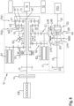
- the Figures 1 to 8 each show transmission arrangements 10 for hybrid vehicles.
- Each transmission arrangement 10 has a housing 11, a transmission input shaft 12 and at least one transmission output shaft 13.
- the transmission input shaft 12 can be connected to an internal combustion engine ICE via a clutch 14 .
- the transmission output shaft 13 is used to drive drive wheels 15 of the hybrid vehicle, reference numeral 16 denoting a differential.
- a first planetary gear set PG1 and a second planetary gear set PG2 are arranged inside the housing 11, the planetary gear sets PG1, PG2 being designed as simple minus gears.
- the first planetary gear set PG1 has a first sun gear zs1, a first ring gear zr1 and a first planetary carrier c1 for a first planetary gear set zp1 meshing with the first sun gear zs1 and the first ring gear zr1.
- the second planetary gear set PG2 has a second sun gear zs2, a second ring gear zr2 and a second planetary carrier c2 for a second planetary gear set zp2 meshing with the second sun gear zs2 and the second ring gear zr2.
- the two ring gears zr1, zr2 are rigidly connected to one another in several pieces or are made in one piece.
- the transmission input shaft 12 is non-rotatably connected to the first planet carrier c1.
- the first Ring gear zr1 and the second ring gear zr2 are permanently connected to one another and to transmission output shaft 13 in a torque-proof manner.
- a first electric machine E1 and a second electric machine E2 are arranged in the housing 11, the first electric machine E1 being permanently drive-connected to the first sun gear zs1 and the second electric machine E2 being drive-connected to the second sun gear zs2 in at least one operating mode of the transmission arrangement 10 .
- the second planetary carrier c2 is connected to the housing 11 .
- the first sun wheel zs1 can be connected to the housing 11 via a first switching element S1.
- the second electrical machine E2 is drive-connected to the second sun gear zs2 or, in some embodiment variants, can be drive-connected to the second sun gear zs2 via a second switching element S2.
- Each of the transmission arrangements 10 shown has an emergency device 17 with an emergency shift element SE, via which the transmission input shaft 12 can be drive-connected to the first planetary carrier c1 and to the first sun gear zs1 at the same time via an intermediate shaft 18 in order to implement a "limp home" function.
- the in the 3 to 6 Transmission arrangements 10 shown each have an emergency device 17 with an emergency switching element SE, via which the transmission input shaft 12 can be drive-connected to implement a "limp home" function via an intermediate shaft 18 only with the second sun gear zs2.
- the transmission arrangement 10 shown has an emergency device 17 with an emergency switching element SEM, via which the transmission input shaft 12 is used to implement a "limp home" function via an intermediate shaft 18 simultaneously with the first planet carrier c1 and optionally via a forward transmission stage GV - for limp home Forward - can be drive-connected to the second sun gear zs2 or alternatively via a reverse gear step GR - which reverses the direction of rotation for limp home backwards - can be drive-connected to the second sun gear zs2.
- SEM emergency switching element
- the embodiment variants shown each have the first switching element S1 in three switching positions, namely L, M and R, with the transmission input shaft 12 being blocked in the left switching position and the first sun gear zs1 being held in place in the right switching position. In the middle position M, neither the transmission input shaft 12 nor the first sun gear zs1 are braked and can rotate freely.
- second switching elements S2 are provided, each of which also has three switching positions, namely 1, 2 and N, whereby in the first switching position 1 the second machine has a first transmission stage G1, and in the second switching position 2 has a second transmission stage G2 with the second sun gear zs2 is drive-connected.
- an emergency device 17 is provided with an emergency switching element SE, with which the input shaft 12 can be drive-connected in addition to the connection to the planetary carrier c1 via the intermediate shaft 18 with the first sun gear zs1.
- the emergency switching element SE has two switching positions, namely "OFF” and “ON”, the "limp-home” function being deactivated in the switching position "OFF” and the direct connection between the transmission input shaft 12 and the first sun gear zs1 being interrupted .
- the emergency switching element SE By moving the emergency switching element SE, the drive connection between the transmission input shaft 12 and the first planetary carrier c1 and the first sun gear zs1 is produced at the same time, and the “limp home” function is thus activated.
- the "limp home” function is activated, for example, in the event of a failure of the controller for the electrical machines E1, E2, which means that the vehicle can continue driving with restricted functionality.
- the 3 to 6 show transmission arrangements 10 according to the invention, which differ from that in 1 , 2 and 7 illustrated embodiments differ in that the transmission input shaft 12 via the intermediate shaft 18 can not be connected to the first sun gear zs1, but with the second sun gear zs2 by the emergency switching element SE.
- the second switching element S2 must also be switched to switch position "1" or switch position "2" in order to enable the "limp home” function.
- the intermediate shaft 18 In the structurally simpler versions of the figure 5 and 6 is the intermediate shaft 18, and the second electric machine E2 drivingly connected directly to the second sun gear zs2 - a second switching element S2 for selecting between gear ratios G1, G2 is not provided.
- the 8 shows a further transmission arrangement 10 according to the invention, which differs from that in Figures 1 - 7 illustrated embodiments differs in that through the emergency switching element SEM, the transmission input shaft 12 simultaneously with the first planetary carrier c1 and via the intermediate shaft 18 optionally via the forward transmission stage GV - forward for limp home (position LHV of the emergency switching element SEM) - with the second sun gear zs2 can be connected to the drive or alternatively via a reverse transmission stage GR - which reverses the direction of rotation for limp home reverse (position LHR of the emergency switching element SEM) - can be drive-connected to the second sun gear zs2.
- the second switching element S2 In the 3 , 4 and 8 the second switching element S2 must also be switched to switch position "1" or switch position "2" in order to enable the "limp home” function.
- the intermediate shaft 18 and the second electrical machine E2 are drive-connected directly to the second sun gear zs2—a second switching element S2 for selecting between gear ratios G1, G2 is not provided.
- the 4 and 6 show other structurally simple design variants in which the first switching element S1 has only two switching positions, namely the switching position "R”, in which the first sun gear zs1 and the first electrical machine E1 are blocked, and the switching position "MR”, in which the first Sun gear zs1 and the first electrical machine E1 are freely rotatable.
- the power take-off shaft 20 can be drive-connected or drive-connectable to the transmission input shaft 12 via an additional shifting element S3 - preferably optionally via a transmission stage G3 - or preferably optionally drive-connected or drive-connectable to the second electrical machine E2 via a transmission stage G4.
- Gear assemblies 10 shown enable the following operating modes: operation mode energy source switching elements Operating mode shown in Fig. ICE E1 E2 SE S.E.M S1 S2 1 OD + BL +, - OFF X R 2, N 1-8 2 eCVT1 + + + OFF X M 1 1-4, 7, 8 3 eCVT2 + + + OFF X M 2 1-8 4 EV1 - + + OFF X M 1, 2 1-4, 7, 8 5 EV2 BL + + OFF X L 1, 2 1-3, 7, 8 6 LH1V + + - ON X M N 1, 2, 7 7 LH2V + - + ON X M, (R) 1, 2 3-6 8th LH3V + - + X LHF M 2 8th 9 LH3R + - + X LHR M 1 8th 10 CHM + + + OFF N M (1), 2 1-8 11 CHS + + - OFF N M (1), 2, (N) 1-8 11 CHS + + - OFF N M (1)
- both the internal combustion engine ICE and the first electric machine E1 can provide drive torque.
- the second electrical machine E2 is uncoupled.
- torque can be introduced into the drive train 19 of the transmission arrangement 10 via different gear ratios G1, G2 by the second electric machine E2.
- the second electrical machine E2 is decoupled from the rest of the transmission.
- Line 1 of the table shows the OD (overdrive) operating mode, which can be used in the upper speed range in particular to reduce fuel consumption, emissions and noise levels.
- the second electrical machine E2 can be mechanically decoupled (position “N” of the second switching element S2) and the first electrical machine E1 blocked (position “R” of the first switching element S1). As a result, losses due to the electrical machines E1 and E2 can be avoided. If required, the second electrical machine E2 can be switched on as a parallel hybrid drive (positions “1” or “2” of the second switching element S2) in order to generate an additional drive torque.
- Row 2 of the table shows the eCVT1 operating mode, in which both the internal combustion engine and the first electric machine E1 and second electric machine E2 are in operation, with the second electric machine E2 being coupled via the first gear ratio G1.
- An electrically assisted continuously variable transmission (eCVT) between the internal combustion engine ICE and the drive wheels 15 can be achieved through targeted activation of the two electrical machines E1, E2.
- This eCVT1 operating mode enables a high drive torque with a high gear ratio of the first gear stage G1.
- Line 3 shows the eCVT2 operating mode, analogous to the eCVT1 operating mode, in which both the internal combustion engine and the first electric machine E1 and second electrical machine E2 are in operation, the second electrical machine E2 being coupled via the second transmission stage G2.
- This eCVT2 operating mode enables high drive speeds with a low gear ratio of the second gear stage G2.
- Line 4 shows the purely electric operating mode EV1, in which the internal combustion engine ICE is switched off but not blocked (the first switching element is in the switching position “M”). Both the first electrical machine E1 and the second electrical machine E2 are activated. The second electrical machine E2 supplies drive torque for the output, with the first electrical machine E1 or alternatively the decoupled internal combustion engine ICE being able to run at a speed that is imposed on it.
- This operating mode is preferably only used for driving on level ground or on small inclines.
- Line 5 shows the purely electric operating mode EV2, in which the internal combustion engine ICE is blocked (the first switching element S1 is in the switching position “L”). Both the first electrical machine E1 and the second electrical machine E2 are activated. Both electrical machines E1 and E2 are used for the drive.
- Line 6 shows the operating mode LH1V ("Limp home”), in which the vehicle is driven only by the internal combustion engine ICE.
- the emergency switching element SE is in the "ON" position, as a result of which the transmission input shaft 12 is drive-connected to the first sun gear zs1 in addition to being connected to the planet carrier c1.
- the first switching element S1 is in the middle position "M", the second switching element S2 in the neutral position "N”.
- the first electrical machine E1 and the second electrical machine E2 can be deactivated.
- Line 7 shows the operating mode LH2V ("Limp home"), in which the vehicle is driven only by the internal combustion engine ICE.
- the emergency switching element SE is in the "ON” position, as a result of which the transmission input shaft 12 is drive-connected to the second sun gear zs2.
- the first switching element S1 is in the middle position "M", the second switching element S2 in position "1" or "2".
- the first electrical machine E1 can be deactivated and the second electrical machine E2 can rotate at a speed that is imposed on it.
- Line 8 shows the operating mode LH3V ("limp home forward"), in which the vehicle is driven only via the internal combustion engine ICE.
- the emergency switching element SEM is in the "LHF” position, whereby the transmission input shaft 12, in addition to being connected to the planet carrier c1, is connected to the second Sun gear zs2 is drive-connected.
- the first switching element S1 is in the middle position "M", the second switching element S2 in position "2".
- the first electrical machine E1 and the second electrical machine E2 can be deactivated.
- Line 9 shows the operating mode LH3R ("limp home reverse"), in which the vehicle is driven only by the internal combustion engine ICE.
- the emergency switching element SEM is in the "LHR” position, as a result of which the transmission input shaft 12 is drive-connected to the second sun gear zs2 in addition to being connected to the planet carrier c1.
- the first switching element S1 is in the middle position "M", the second switching element S2 in position "1".
- the first electrical machine E1 and the second electrical machine E2 can be deactivated.
- Lines 10 and 11 show the CHM and CHS operating modes for charging the vehicle battery, either while driving (CHM operating mode) or while the vehicle is stationary (CHS operating mode).
- CHM operating mode the internal combustion engine ICE and the first electrical machine E1 are activated.
- the second electric machine E2 is also activated and is connected to the second sun gear zs2 either via the first transmission stage G1 or the second transmission stage G2.
- the second electrical machine E2 is deactivated and is either connected to the drive train 19 of the transmission arrangement 10 via the first gear ratio G1 or the second gear ratio G2 (shift position "1" or “2" of the second shift element S2) or separated from it (shift position "N" of the second switching element S2).
Landscapes
- Engineering & Computer Science (AREA)
- Mechanical Engineering (AREA)
- Chemical & Material Sciences (AREA)
- Combustion & Propulsion (AREA)
- Transportation (AREA)
- General Engineering & Computer Science (AREA)
- Structure Of Transmissions (AREA)
- Hybrid Electric Vehicles (AREA)
Description
- Die Erfindung betrifft eine Getriebeanordnung für ein Hybridfahrzeug, mit einem Gehäuse, mit einer Getriebeeingangswelle und zumindest einer Getriebeausgangswelle, mit einem ersten Planetengetriebesatz mit einem ersten Sonnenrad, einem ersten Hohlrad und einem ersten Planetenträger für einen mit dem ersten Sonnenrad und dem ersten Hohlrad im Zahneingriff stehenden ersten Planetenradsatz, mit einem zweiten Planetengetriebesatz mit einem zweiten Sonnenrad, einem zweiten Hohlrad und einem zweiten Planetenträger für einen mit dem zweiten Sonnenrad und dem zweiten Hohlrad im Zahneingriff stehenden zweiten Planetenradsatz, wobei die Getriebeeingangswelle mit dem ersten Planetenträger drehfest verbunden oder verbindbar ist und das erste und zweite Hohlrad permanent miteinander und mit der Getriebeausgangswelle drehfest verbunden sind, mit einer ersten elektrischen Maschine und einer zweiten elektrischen Maschine, wobei die erste elektrische Maschine permanent mit dem ersten Sonnenrad antriebsverbunden und die zweite elektrische Maschine in zumindest einem Betriebsmodus mit dem zweiten Sonnenrad antriebsverbunden ist, und wobei das erste Sonnenrad über ein erstes Schaltelement mit dem Gehäuse verbindbar ist, wobei der zweite Planetenträger fest mit dem Gehäuse verbunden ist und die zweite elektrische Maschine mit dem zweiten Sonnenrad antriebsverbunden oder antriebsverbindbar ist.
- Weiters betrifft die Erfindung ein Verfahren zum Betreiben eines Hybridfahrzeuges mit einer Getriebeanordnung der genannten Art.
- Aus der
DE 10 2013 113 344 A1 ist ein Leistungsübertragungssystem für ein Hybrid-Elektrofahrzeug mit einem ersten und einem zweiten Planetengetriebesatz bekannt, von denen einer als Minusgetriebe und der andere als Plusgetriebe ausgebildet ist. Dabei sind eine erste elektrische Maschine und eine zweite elektrische Maschine koaxial zur Getriebeeingangswelle angeordnet, wobei die erste elektrische Maschine fest mit dem Sonnenrad des ersten Planetengetriebesatzes und die zweite elektrische Maschine fest mit dem Sonnenrad des zweiten Planetengetriebesatzes verbunden ist. Die Planetenträger der beiden Planetengetriebesätze sind über eine Reibungskupplung miteinander drehverbindbar. Das Sonnenrad des ersten Planetengetriebesatzes kann über eine erste Reibungsbremse, und der Planetenträger des zweiten Planetengetriebesatzes über eine zweite Reibungsbremse festgehalten werden. - Die
DE 10 2013 226 472 A1 beschreibt ein Kraftübertragungssystem für ein Hybridfahrzeug mit einem ersten Planetenradsatz und einem zweiten Planetenradsatz. Der Planetenträger des ersten Planetenradsatzes ist mit der Abtriebswelle einer Brennkraftmaschine verbunden. Die Hohlräder der beiden Planetenradsätze sind miteinander verbunden und wirken auf eine Antriebseinheit ein. Der Planetenträger des zweiten Planetenradsatzes ist über eine Bremse festhaltbar. Der Planetenträger des ersten Planetenradsatzes ist über eine Kupplung mit den Hohlrädern verbindbar. Weiters ist das Sonnenrad des ersten Planetenradsatzes mit einer ersten elektrischen Maschine und das Sonnenrad des zweiten Planetenradsatzes mit einer zweiten elektrischen Maschine verbunden. - Die
DE 11 2007 002 558 B4 beschreibt eine in einem Getriebegehäuse angeordnete Leistungsabgabevorrichtung mit einer Brennkraftmaschine, einem ersten Motor, einem zweiten Motor, mit einem durch ein erstes Planetengetriebe gebildeten Leistungsverteilungsintegrationsmechanismus und einem durch ein zweites Planetengetriebe gebildeten Untersetzungsgetriebemechanismus. Weiters ist in dem Getriebegehäuse zwischen der Leistungsabgabevorrichtung und einer dem Antrieb der Antriebsräder dienenden Antriebswelle ein Getriebe angeordnet. Die Motoren und die Brennkraftmaschine sind über zwei gekoppelte Planetengetriebe miteinander verbunden. Der erste Elektromotor ist mit einem Sonnenrad des ersten Planetengetriebes verbindbar und der zweite Motor ist mit einem Sonnenrad des zweiten Planetengetriebes verbunden. Die Brennkraftmaschine ist mit dem Planetenträger des ersten Planetengetriebes verbunden. Die beiden Planetengetriebe sind über ein gemeinsames Hohlrad miteinander verbunden. Die Motorwelle des ersten Motors wirkt auf eine zweite Zahnradwelle, das gemeinsame Hohlrad der Planetengetriebe wirkt auf eine erste Zahnradwelle des Getriebes ein, wobei die Zahnradwellen über eine Kupplung entweder direkt oder über eine Getriebezwischenwelle mit der Antriebswelle verbindbar sind. - Ausgehend von einer Getriebeanordnung der eingangs genannten Art ist es die Aufgabe der Erfindung, auf möglichst einfache Weise und unter Beanspruchung von wenig Bauraum eine hohe Funktionalität mit vielen Betriebsmodi zu erreichen.
- Erfindungsgemäß wird dies dadurch erreicht, dass
- in einem Notfall-Modus der Getriebeanordnung die Getriebeeingangswelle über ein Notfall-Schaltelement zusätzlich zu einer drehfesten Verbindung zum ersten Planetenträger mit dem ersten Sonnenrad antriebsverbindbar ist,
oder dass - in einem Notfall-Modus der Getriebeanordnung die Getriebeeingangswelle über ein Notfall-Schaltelement bei getrennter Verbindung zum ersten Planetenträger mit dem zweiten Sonnenrad antriebsverbindbar ist,
oder dass - in einem Notfall-Modus der Getriebeanordnung die Getriebeeingangswelle über ein Notfall-Schaltelement zusätzlich zu einer drehfesten Verbindung zum ersten Planetenträger wahlweise über eine erste Vorwärtsübersetzungsstufe mit dem zweiten Sonnenrad oder über eine Rückwärts-Übersetzungsstufe - welche die Drehrichtung umkehrt - mit dem zweiten Sonnenrad antriebsverbindbar ist.
- Dadurch kann bei Ausfall beispielsweise der Steuerung für die elektrischen Maschinen eine sogenannte "Limp home" Funktion ermöglicht werden. Um im Falle einer Störung eine Weiterfahrt mit reduzierter Funktionalität zu ermöglichen, wird im Notfall-Modus die Getriebeeingangswelle mit dem ersten Sonnenrad oder dem zweiten Sonnenrad antriebsverbunden.
- Vorzugsweise ist vorgesehen, dass die zweite elektrische Maschine über ein zweites Schaltelement - vorzugsweise wahlweise über eine erste oder zweite Übersetzungsstufe - mit dem zweiten Sonnenrad antriebsverbindbar ist.
- In einer konstruktiv einfachen und kompakten Ausführung der Erfindung ist vorgesehen, dass sowohl der erste als auch der zweite Planetenradsatz als einfache Minusgetriebe ausgebildet sind.
- Eine sehr platzsparende Bauweise wird ermöglicht, wenn die Getriebeausgangswelle koaxial zur Getriebeeingangswelle angeordnet ist.
- Eine Ausführungsvariante der Erfindung sieht vor, dass die erste elektrische Maschine und die zweite elektrische Maschine achsversetzt und parallel zueinander, vorzugsweise auch achsversetzt in Bezug zur Getriebeeingangswelle und/oder Getriebeausgangswelle - angeordnet sind. Dies ermöglicht eine optimale Nutzung des zur Verfügung stehenden Bauraumes. Durch die Verwendung von kompakten elektrischen Maschinen mit hohen Drehzahlen kann der verbaute Raum reduziert und Kosten eingespart werden. Die elektrischen Maschinen können beispielsweise im Bereich einer Stirnseite der Getriebeanordnung vorgesehen werden, wodurch der Platz optimal ausgenutzt und kurz bauende Anordnungen realisiert werden können. Ein weiterer Vorteil ergibt sich durch die einfachere Montage.
- In einer weiteren Ausführungsvariante ist vorgesehen, dass die Getriebeeingangswelle - vorzugsweise über eine Übersetzungsstufe - mit einer Nebenabtriebswelle antriebsverbunden oder antriebsverbindbar ist. Dies ermöglicht es, gegebenenfalls Zusatzaggregate oder externe Maschinen anzutreiben.
- In weiteren Ausführungsvarianten ist vorgesehen, dass eine Nebenabtriebswelle über ein Schaltelement -vorzugsweise über eine Übersetzungsstufe - mit der Getriebeeingangswelle antriebsverbunden oder antriebsverbindbar ist oder - vorzugsweise über eine Übersetzungsstufe - mit der zweiten elektrischen Maschine antriebsverbunden oder antriebsverbindbar ist. Dies ermöglicht es, gegebenenfalls Zusatzaggregate oder externe Maschinen wahlweise mechanisch oder elektrisch anzutreiben.
- Im Rahmen der Erfindung ist vorgesehen, dass in einem Overdrive-Modus des Hybridfahrzeuges die erste elektrische Maschine blockiert wird, wobei das erste Sonnenrad über ein erstes Schaltelement mit dem Gehäuse verbunden wird. Unter einem Overdrive-Modus wird ein Schongang der Getriebeanordnung verstanden, der eine Absenkung der für eine bestimmte Geschwindigkeit notwenigen Motordrehzahl bewirkt. Durch Ermöglichung des Overdrive-Modus kann der Kraftstoffverbrauch, die Emissionen, der Geräuschpegel, sowie die Belastung des Triebwerkes insbesondere bei Überlandfahrten des Hybridfahrzeuges wesentlich reduziert werden. Zur Minimierung der Verluste wird vorzugsweise im Overdrive-Modus die zweite elektrische Maschine über das zweite Schaltelement mechanisch vom Antriebsstrang getrennt.
- Die Erfindung wird im Folgenden anhand der in den Figuren gezeigten nicht einschränkenden Ausführungsbeispielen näher erläutert. Darin zeigen schematisch:
- Fig. 1
- eine erfindungsgemäße Getriebeanordnung in einer ersten Ausführung der Erfindung;
- Fig. 2
- eine erfindungsgemäße Getriebeanordnung in einer zweiten Ausführung der Erfindung;
- Fig. 3
- eine erfindungsgemäße Getriebeanordnung in einer dritten Ausführung der Erfindung;
- Fig. 4
- eine erfindungsgemäße Getriebeanordnung in einer vierten Ausführung der Erfindung;
- Fig. 5
- eine erfindungsgemäße Getriebeanordnung in einer fünften Ausführung der Erfindung;
- Fig. 6
- eine erfindungsgemäße Getriebeanordnung in einer sechsten Ausführung der Erfindung;
- Fig. 7
- eine erfindungsgemäße Getriebeanordnung in einer siebenten Ausführung der Erfindung; und
- Fig. 8
- eine erfindungsgemäße Getriebeanordnung in einer achten Ausführung der Erfindung.
- Funktionsgleiche Teile sind in den Ausführungsvarianten mit den gleichen Bezugszeichen versehen.
- Die
Fig. 1 bis Fig. 8 zeigen jeweils Getriebeanordnungen 10 für Hybridfahrzeuge. - Jede Getriebeanordnung 10 weist ein Gehäuse 11, eine Getriebeeingangswelle 12 und zumindest eine Getriebeausgangswelle 13 auf. Die Getriebeeingangswelle 12 kann über eine Schaltkupplung 14 mit einer Brennkraftmaschine ICE verbunden werden. Die Getriebeausgangswelle 13 dient zum Antrieb von Antriebsrädern 15 des Hybridfahrzeuges, wobei mit Bezugszeichen 16 ein Differential bezeichnet ist. Innerhalb des Gehäuses 11 ist ein erster Planetengetriebesatz PG1 und ein zweiter Planetengetriebesatz PG2 angeordnet, wobei die Planetengetriebesätze PG1, PG2 als einfache Minusgetriebe ausgebildet sind.
- Der erste Planetengetriebesatz PG1 weist ein erstes Sonnenrad zs1, ein erstes Hohlrad zr1 und einen ersten Planetenträger c1 für einen mit dem ersten Sonnenrad zs1 und dem ersten Hohlrad zr1 im Zahneingriff stehenden ersten Planetenradsatz zp1 auf. Der zweite Planetengetriebesatz PG2 weist ein zweites Sonnenrad zs2, ein zweites Hohlrad zr2 und einen zweiten Planetenträger c2 für einen mit dem zweiten Sonnenrad zs2 und dem zweiten Hohlrad zr2 im Zahneingriff stehenden zweiten Planetenradsatz zp2 auf. Die beiden Hohlräder zr1, zr2 sind mehrstückig starr miteinander verbunden oder einstückig ausgeführt. Die Getriebeeingangswelle 12 ist mit dem ersten Planetenträger c1 drehfest verbunden. Das erste Hohlrad zr1 und das zweite Hohlrad zr2 sind permanent miteinander und mit der Getriebeausgangswelle 13 drehfest verbunden. Im Gehäuse 11 ist eine erste elektrische Maschine E1 und eine zweite elektrische Maschine E2 angeordnet, wobei die erste elektrische Maschine E1 permanent mit dem ersten Sonnenrad zs1 antriebsverbunden und die zweite elektrische Maschine E2 in zumindest einem Betriebsmodus der Getriebeanordnung 10 mit dem zweiten Sonnenrad zs2 antriebsverbunden ist. Der zweite Planetenträger c2 ist mit dem Gehäuse 11 verbunden.
- Das erste Sonnenrad zs1 kann über ein erstes Schaltelement S1 mit dem Gehäuse 11 verbunden werden.
- Die zweite elektrische Maschine E2 ist mit dem zweiten Sonnenrad zs2 antriebsverbunden oder kann in einigen Ausführungsvarianten über ein zweites Schaltelement S2 mit dem zweiten Sonnenrad zs2 antriebsverbunden werden.
- Weiters weisen die in den
Fig. 1 ,Fig. 2 undFig. 7 gezeigten Getriebeanordnungen 10 jeweils eine Notfalleinrichtung 17 mit einem Notfall-Schaltelement SE auf, über welches die Getriebeeingangswelle 12 zur Verwirklichung einer "Limp Home"-Funktion über eine Zwischenwelle 18 gleichzeitig mit dem ersten Planetenträger c1-und mit dem ersten Sonnenrad zs1 antriebsverbunden werden kann. - Weiters weisen die in den
Fig. 3 bis Fig. 6 gezeigten Getriebeanordnungen 10 jeweils eine Notfalleinrichtung 17 mit einem Notfall-Schaltelement SE auf, über welches die Getriebeeingangswelle 12 zur Verwirklichung einer "Limp Home"- Funktion über eine Zwischenwelle 18 nur mit dem zweiten Sonnenrad zs2 antriebsverbunden werden kann. - Weiters weist die in der
Fig. 8 gezeigte Getriebeanordnung 10 eine Notfalleinrichtung 17 mit einem Notfall-Schaltelement SEM auf, über welches die Getriebeeingangswelle 12 zur Verwirklichung einer "Limp Home"- Funktion über eine Zwischenwelle 18 gleichzeitig mit dem ersten Planetenträger c1 und wahlweise über eine Vorwärts-Übersetzungsstufe GV - für Limp Home Vorwärts - mit dem zweiten Sonnenrad zs2 antriebsverbunden werden kann oder wahlweise über eine Rückwärts-Übersetzungsstufe GR - welche die Drehrichtung für Limp Home Rückwärts umkehrt - mit dem zweiten Sonnenrad zs2 antriebsverbunden werden kann. - In den in den
Fig. 1 ,Fig. 2 ,Fig. 3 ,Fig. 5 ,Fig. 7 undFig. 8 gezeigten Ausführungsvarianten weist jeweils das erste Schaltelement S1 drei Schaltstellungen, nämlich L, M und R auf, wobei in der linken Schaltstellung die Getriebeeingangswelle 12 blockiert und in der rechten Schaltstellung das erste Sonnenrad zs1 festgehalten ist. In der Mittelstellung M werden weder die Getriebeeingangswelle 12, noch das erste Sonnenrad zs1 gebremst und können sich frei drehen. - Weiters sind in
Fig. 1 ,Fig. 2 ,Fig. 3 ,Fig. 4 ,Fig. 7 undFig. 8 zweite Schaltelemente S2 vorgesehen, welche jeweils ebenfalls drei Schaltstellungen, nämlich 1, 2 und N aufweisen, wobei in der ersten Schaltstellung 1 die zweite Maschine über eine erste Übersetzungsstufe G1, und in der zweiten Schaltstellung 2 über eine zweite Übersetzungsstufe G2 mit dem zweiten Sonnenrad zs2 antriebsverbunden ist. - Weiters ist in den Ausführungsvarianten nach
Fig. 1 ,Fig. 2 undFig. 7 eine Notfalleinrichtung 17 mit einem Notfall-Schaltelement SE vorgesehen, mit welchem die Eingangswelle 12 zusätzlich zur Verbindung zum Planetenträger c1 über die Zwischenwelle 18 mit dem ersten Sonnenrad zs1 antriebsverbunden werden kann. Das Notfall-Schaltelement SE weist zwei Schaltstellungen, nämlich "OFF" und "ON" auf, wobei in der Schaltstellung "OFF" die "Limp-home"-Funktion deaktiviert und die direkte Verbindung zwischen der Getriebeeingangswelle 12 und dem ersten Sonnenrad zs1 unterbrochen ist. Durch Verschieben des Notfall-Schaltelementes SE wird die Antriebsverbindung zwischen der Getriebeeingangswelle 12 gleichzeitig mit dem ersten Planetenträger c1 und dem ersten Sonnenrad zs1 hergestellt und somit die "Limp home"-Funktion aktiviert. Die Aktivierung der "Limp home"-Funktion erfolgt beispielsweise im Falle eines Ausfalles der Steuerung für die elektrischen Maschinen E1, E2, wodurch eine Weiterfahrt des Fahrzeuges mit eingeschränkter Funktionalität möglich ist. - Die
Fig. 3 bis Fig. 6 zeigen erfindungsgemäße Getriebeanordnungen 10, welche sich von dem inFig. 1 ,Fig. 2 undFig. 7 dargestellten Ausführungsbeispielen dadurch unterscheiden, dass durch das Notfall-Schaltelement SE die Getriebeeingangswelle 12 über die Zwischenwelle 18 nicht mit dem ersten Sonnenrad zs1, sondern mit dem zweiten Sonnenrad zs2 verbunden werden kann. In denFig. 3 undFig. 4 muss zusätzlich das zweite Schaltelement S2 in die Schaltstellung "1" oder die Schaltstellung "2" geschaltet werden, um die "Limp Home"-Funktion zu ermöglichen. Bei den konstruktiv einfacheren Ausführungen derFig. 5 undFig. 6 ist die Zwischenwelle 18, sowie die zweite elektrische Maschine E2 direkt mit dem zweiten Sonnenrad zs2 antriebsverbunden - ein zweites Schaltelement S2 zum Auswählen zwischen Übersetzungsstufen G1, G2 ist nicht vorgesehen. - Die
Fig. 8 zeigt eine weitere erfindungsgemäße Getriebeanordnung 10, welche sich von den inFig. 1 - Fig. 7 dargestellten Ausführungsbeispielen dadurch unterscheidet, das durch das Notfall-Schaltelement SEM die Getriebeeingangswelle 12 gleichzeitig mit dem ersten Planetenträger c1 und über die Zwischenwelle 18 wahlweise über die Vorwärts-Übersetzungsstufe GV - für Limp Home Vorwärts (Stellung LHV des Notfallschaltelementes SEM)- mit dem zweiten Sonnenrad zs2 antriebsverbunden werden kann oder wahlweise über eine Rückwärts-Übersetzungsstufe GR - welche die Drehrichtung für Limp Home Rückwärts (Stellung LHR des Notfallschaltelementes SEM) umkehrt - mit dem zweiten Sonnenrad zs2 antriebsverbunden werden kann. - In den
Fig. 3 ,Fig. 4 undFig. 8 muss zusätzlich das zweite Schaltelement S2 in die Schaltstellung "1" oder die Schaltstellung "2" geschaltet werden, um die "Limp Home"-Funktion zu ermöglichen. Bei den konstruktiv einfacheren Ausführungen derFig. 5 undFig. 6 ist die Zwischenwelle 18 sowie die zweite elektrische Maschine E2 direkt mit dem zweiten Sonnenrad zs2 antriebsverbunden - ein zweites Schaltelement S2 zum Auswählen zwischen Übersetzungsstufen G1, G2 ist nicht vorgesehen. - Die
Fig. 4 undFig. 6 zeigen weitere konstruktiv einfache Ausführungsvarianten, bei denen das erste Schaltelement S1 nur zwei Schaltstellungen aufweist, nämlich die Schaltstellung "R", bei der das erste Sonnenrad zs1 und die erste elektrische Maschine E1 blockiert sind, und die Schaltstellung "MR", bei der das erste Sonnenrad zs1 und die erste elektrische Maschine E1 frei drehbar sind. - Weiters können verschiedene Varianten zur Realisierung des Nebenabtriebs PTO unabhängig von den Ausführungsvarianten dargestellt werden. Vorzugsweise wie bei der in
Fig. 1 dargestellten Getriebeanordnung 10 kann optional ein elektrisch angetriebener Nebenabtrieb PTO verbaut sein. Vorzugsweise kann wie bei der inFig. 2 gezeigten zweiten Ausführung ein mechanisch über die Getriebeeingangswelle 12 angetriebener Nebenabtrieb PTO vorgesehen werden. - Vorzugsweise kann wie bei den in
Fig. 7 undFig. 8 gezeigten Ausführungsvarianten zur Realisierung des Nebenabtriebs PTO die Nebenabtriebswelle 20 über ein zusätzliches Schaltelement S3 - vorzugsweise wahlweise über eine Übersetzungsstufe G3 - mit der Getriebeeingangswelle 12 antriebsverbunden oder antriebsverbindbar werden oder vorzugsweise wahlweise über eine Übersetzungsstufe G4 mit der zweiten elektrischen Maschine E2 antriebsverbunden oder antriebsverbindbar werden. - Die in den
Fig. 1 bis Fig. 8 dargestellten Getriebeanordnungen 10 ermöglichen folgende Betriebsmodi:Betriebsmodus Energiequelle Schaltelemente Betriebsmodus dargestellt in Fig. ICE E1 E2 SE SEM S1 S2 1 OD + BL +, - OFF X R 2, N 1-8 2 eCVT1 + + + OFF X M 1 1-4, 7, 8 3 eCVT2 + + + OFF X M 2 1-8 4 EV1 - + + OFF X M 1, 2 1-4, 7, 8 5 EV2 BL + + OFF X L 1, 2 1-3, 7, 8 6 LH1V + + - ON X M N 1, 2, 7 7 LH2V + - + ON X M, (R) 1, 2 3-6 8 LH3V + - + X LHF M 2 8 9 LH3R + - + X LHR M 1 8 10 CHM + + + OFF N M (1), 2 1-8 11 CHS + + - OFF N M (1), 2, (N) 1-8 - In der Tabelle bedeuten: "+" aktivierte Maschine, "-" deaktivierte Maschine und "BL" blockierte Maschine. "X" bedeutet nicht vorhandenes Schaltelement. Die Schaltstellungen "OFF", "ON" des Notfallschaltelementes SE; "LHF", "N", "LHR" des Notfallschaltelementes SEM; "L", "M", "R" des ersten Schaltelementes S1; und "1", "N", "2" des zweiten Schaltelementes S2 entsprechen je nach Darstellung den in den
Fig. 1 bis Fig. 8 angedeuteten Schaltpositionen der Schaltelemente SE, SEM, S1, S2. In der Schaltstellung L des ersten Schaltelementes S1 wird die Brennkraftmaschine ICE, in der Schaltstellung R des ersten Schaltelementes S1 die erste elektrische Maschine S1 blockiert. In der Mittelstellung M können sowohl die Brennkraftmaschine ICE, als auch die erste elektrische Maschine E1 Antriebsdrehmoment zur Verfügung stellen. In der Position "N" ist die zweite elektrische Maschine E2 abgekoppelt. In den Schaltstellungen 1 und 2 kann Drehmoment über unterschiedliche Übersetzungsstufen G1, G2 durch die zweite elektrische Maschine E2 in den Antriebsstrang 19 der Getriebeanordnung 10 eingebracht werden. In der Stellung "N" ist die zweite elektrische Maschine E2 vom restlichen Getriebe entkoppelt. - Zeile 1 der Tabelle zeigt den Betriebsmodus OD (Overdrive), welcher insbesondere im oberen Geschwindigkeitsbereich eingesetzt werden kann, um Kraftstoffverbrauch, Emissionen und Lärmpegel zu verringern. Dabei ist bevorzugt nur die Brennkraftmaschine ICE in Betrieb und kann bei optimaler Drehzahl betrieben werden. Die zweite elektrische Maschine E2 kann mechanisch abgekoppelt werden (Position "N" des zweiten Schaltelementes S2) und die erste elektrische Maschine E1 blockiert werden (Position "R" des ersten Schaltelementes S1). Dadurch können Verluste durch die elektrischen Maschinen E1 und E2 vermieden werden. Bei Bedarf kann die zweite elektrische Maschine E2 als Parallelhybrid-Antrieb dazu geschalten werden (Positionen "1" oder "2" des zweiten Schaltelementes S2), um ein zusätzliches Antriebsdrehmoment zu erzeugen.
- Zeile 2 der Tabelle zeigt den Betriebsmodus eCVT1, bei dem sowohl die Brennkraftmaschine, als auch die erste elektrische Maschine E1 und zweite elektrische Maschine E2 in Betrieb sind, wobei die zweite elektrische Maschine E2 über die erste Übersetzungsstufe G1 angekoppelt ist. Durch gezielte Ansteuerung der beiden elektrischen Maschinen E1, E2 kann eine elektrisch unterstützte kontinuierlich variable Übersetzung (eCVT) zwischen der Brennkraftmaschine ICE und den Antriebsrädern 15 erzielt werden. Dieser Betriebsmodus eCVT1 ermöglicht ein hohes Antriebsdrehmoment bei hohem Übersetzungsverhältnis der ersten Übersetzungsstufe G1.
- Zeile 3 zeigt analog zum Betriebsmodus eCVT1 den Betriebsmodus eCVT2, bei dem sowohl die Brennkraftmaschine als auch die erste elektrische Maschine E1 und zweite elektrische Maschine E2 in Betrieb sind, wobei die zweite elektrische Maschine E2 über die zweite Übersetzungsstufe G2 angekoppelt ist. Dieser Betriebsmodus eCVT2 ermöglicht hohe Antriebsdrehzahlen bei niedrigem Übersetzungsverhältnis der zweiten Übersetzungsstufe G2.
- Zeile 4 zeigt den rein elektrischen Betriebsmodus EV1, bei dem die Brennkraftmaschine ICE ausgeschaltet, aber nicht blockiert ist (das erste Schaltelement befindet sich in der Schaltposition "M"). Sowohl die erste elektrische Maschine E1, als auch die zweite elektrische Maschine E2 sind aktiviert. Die zweite elektrische Maschine E2 gibt Antriebsdrehmoment für den Abtrieb ab, wobei die erste elektrische Maschine E1 oder wahlweise die ausgekuppelte Brennkraftmaschine ICE mit einer ihr aufgezwungenen Drehzahl mitlaufen kann. Dieser Betriebsmodus wird vorzugsweise nur für den Antrieb in der Ebene oder bei kleinen Steigungen verwendet.
- Zeile 5 zeigt den rein elektrischen Betriebsmodus EV2, bei dem die Brennkraftmaschine ICE blockiert ist (das erste Schaltelement S1 befindet sich in der Schaltposition "L"). Sowohl die erste elektrische Maschine E1, als auch die zweite elektrische Maschine E2 sind aktiviert. Beide elektrische Maschinen E1 und E2 werden für den Antrieb verwendet.
- Zeile 6 zeigt den Betriebsmodus LH1V ("Limp home"), bei dem der Antrieb des Fahrzeuges nur über die Brennkraftmaschine ICE erfolgt. Das Notfall-Schaltelement SE befindet sich in der Stellung "ON", wodurch die Getriebeeingangswelle 12 zusätzlich zur Verbindung zum Planetenträger c1 mit dem ersten Sonnenrad zs1 antriebsverbunden ist. Das erste Schaltelement S1 befindet sich in der Mittelposition "M", das zweite Schaltelement S2 in der Neutralstellung "N". Die erste elektrische Maschine E1 und die zweite elektrische Maschine E2 können deaktiviert sein.
- Zeile 7 zeigt den Betriebsmodus LH2V ("Limp home"), bei dem der Antrieb des Fahrzeuges nur über die Brennkraftmaschine ICE erfolgt. Das Notfall-Schaltelement SE befindet sich in der Stellung "ON", wodurch die Getriebeeingangswelle 12 mit dem zweiten Sonnenrad zs2 antriebsverbunden ist. Das erste Schaltelement S1 befindet sich in der Mittelposition "M", das zweite Schaltelement S2 in der Position "1" oder "2". Die erste elektrische Maschine E1 kann deaktiviert sein und die zweite elektrische Maschine E2 kann mit einer ihr aufgezwungenen Drehzahl mitdrehen.
- Zeile 8 zeigt den Betriebsmodus LH3V ("Limp home Vorwärts"), bei dem der Antrieb des Fahrzeuges nur über die Brennkraftmaschine ICE erfolgt. Das Notfall-Schaltelement SEM befindet sich in der Stellung "LHF", wodurch die Getriebeeingangswelle 12 zusätzlich zur Verbindung zum Planetenträger c1 mit dem zweiten Sonnenrad zs2 antriebsverbunden ist. Das erste Schaltelement S1 befindet sich in der Mittelposition "M", das zweite Schaltelement S2 in der Stellung "2". Die erste elektrische Maschine E1 und die zweite elektrische Maschine E2 können deaktiviert sein.
- Zeile 9 zeigt den Betriebsmodus LH3R ("Limp home Rückwärts"), bei dem der Antrieb des Fahrzeuges nur über die Brennkraftmaschine ICE erfolgt. Das Notfall-Schaltelement SEM befindet sich in der Stellung "LHR", wodurch die Getriebeeingangswelle 12 zusätzlich zur Verbindung zum Planetenträger c1 mit dem zweiten Sonnenrad zs2 antriebsverbunden ist. Das erste Schaltelement S1 befindet sich in der Mittelposition "M", das zweite Schaltelement S2 in der Stellung "1". Die erste elektrische Maschine E1 und die zweite elektrische Maschine E2 können deaktiviert sein.
- Die Zeilen 10 und 11 zeigen die Betriebsmodi CHM und CHS, für das Laden der Fahrzeugbatterie, entweder während des Fahrbetriebes (Betriebsmodus CHM) oder während des Stillstandes des Fahrzeuges (Betriebsmodus CHS). Dabei sind die Brennkraftmaschine ICE und die erste elektrische Maschine E1 aktiviert. Im Betriebsmodus CHM ist auch die zweite elektrische Maschine E2 aktiviert und entweder über die erste Übersetzungsstufe G1 oder die zweite Übersetzungsstufe G2 mit dem zweiten Sonnenrad zs2 verbunden. Im Betriebsmodus CHS ist die zweite elektrische Maschine E2 deaktiviert und entweder über die erste Übersetzungsstufe G1 oder die zweite Übersetzungsstufe G2 an den Antriebsstrang 19 der Getriebeanordnung 10 angebunden (Schaltstellung "1" oder "2" des zweiten Schaltelementes S2) oder von diesem getrennt (Schaltstellung "N" des zweiten Schaltelementes S2).
Claims (11)
- Getriebeanordnung (10) für ein Hybridfahrzeug, mit einem Gehäuse (11), mit einer Getriebeeingangswelle (12) und zumindest einer Getriebeausgangswelle (13), die zum Antrieb von Antriebsrädern (15) dient, mit einem ersten Planetengetriebesatz (PG1) mit einem ersten Sonnenrad (zs1), einem ersten Hohlrad (zr1) und einem ersten Planetenträger (c1) für einen mit dem ersten Sonnenrad (zs1) und dem ersten Hohlrad (zr1) im Zahneingriff stehenden ersten Planetenradsatz (zp1), mit einem zweiten Planetengetriebesatz (PG2) mit einem zweiten Sonnenrad (zs2), einem zweiten Hohlrad (zr2) und einem zweiten Planetenträger (c2) für einen mit dem zweiten Sonnenrad (zs2) und dem zweiten Hohlrad (zr2) im Zahneingriff stehenden zweiten Planetenradsatz (zp2), wobei die Getriebeeingangswelle (12) mit dem ersten Planetenträger (c1) drehfest verbunden oder verbindbar ist und das erste Hohlrad (zr1) und zweite Hohlrad (zr2) permanent miteinander und mit der Getriebeausgangswelle (13) drehfest verbunden sind, mit einer ersten elektrischen Maschine (E1) und einer zweiten elektrischen Maschine (E2), wobei die erste elektrische Maschine (E1) permanent mit dem ersten Sonnenrad (zs1) antriebsverbunden und die zweite elektrische Maschine (E2) in zumindest einem Betriebsmodus mit dem zweiten Sonnenrad (zs2) antriebsverbunden ist, und wobei das erste Sonnenrad (zs1) über ein erstes Schaltelement (S1) mit dem Gehäuse (11) verbindbar ist, wobei der zweite Planetenträger (c2) fest mit dem Gehäuse (11) verbunden ist und die zweite elektrische Maschine (E2) mit dem zweiten Sonnenrad (zs2) antriebsverbunden oder antriebsverbindbar ist, dadurch gekennzeichnet, dass• in einem Notfall-Modus (LH) der Getriebeanordnung (10) die Getriebeeingangswelle (12) über ein Notfall-Schaltelement (SE) zusätzlich zu einer drehfesten Verbindung zum ersten Planetenträger (c1) mit dem ersten Sonnenrad (zs1) antriebsverbindbar ist,
oder dass• in einem Notfall-Modus (LH) der Getriebeanordnung (10) die Getriebeeingangswelle (12) über ein Notfall-Schaltelement (SE) bei getrennter Verbindung zum ersten Planetenträger (c1) mit dem zweiten Sonnenrad (zs2) antriebsverbindbar ist,
oder dass• in einem Notfall-Modus (LH) der Getriebeanordnung (10) die Getriebeeingangswelle (12) über ein Notfall-Schaltelement (SEM) zusätzlich zu einer drehfesten Verbindung zum ersten Planetenträger (c1) wahlweise über eine erste Vorwärtsübersetzungsstufe (GV) mit dem zweiten Sonnenrad (zs2) oder über eine Rückwärts-Übersetzungsstufe (GR) - welche die Drehrichtung umkehrt - mit dem zweiten Sonnenrad (zs2) antriebsverbindbar ist. - Getriebeanordnung (10) nach Anspruch 1, dadurch gekennzeichnet, dass die zweite elektrische Maschine (E2) über ein zweites Schaltelement (S2) - vorzugsweise wahlweise über eine erste (G1) oder zweite Übersetzungsstufe (G2) - mit dem zweiten Sonnenrad (zs2) antriebsverbindbar ist.
- Getriebeanordnung (10) nach Anspruch 1 oder 2, dadurch gekennzeichnet, dass die zweite elektrische Maschine (E2) über zumindest eine Übersetzungsstufe (G1, G2) mit dem zweiten Sonnenrad (zs2) antriebsverbunden oder antriebsverbindbar ist.
- Getriebeanordnung (10) nach einem der Ansprüche 1 bis 3, dadurch gekennzeichnet, dass die Getriebeeingangswelle (12) - vorzugsweise über das erste Schaltelement (S1) - mit dem Gehäuse (11) verbindbar ist.
- Getriebeanordnung (10) nach einem der Ansprüche 1 bis 4, dadurch gekennzeichnet, dass die Getriebeausgangswelle (13) koaxial zur Getriebeeingangswelle (12) angeordnet ist.
- Getriebeanordnung (10) nach einem der Ansprüche 1 bis 5, dadurch gekennzeichnet, dass die erste elektrische Maschine (E1) und die zweite elektrische Maschine (E2) achsversetzt zueinander, vorzugsweise auch achsversetzt in Bezug zur Getriebeeingangswelle (12) und/oder Getriebeausgangswelle (13) - angeordnet sind.
- Getriebeanordnung (10) nach einem der Ansprüche 1 bis 6, dadurch gekennzeichnet, dass die Getriebeeingangswelle (12) - vorzugsweise über eine Übersetzungsstufe (G1, G2) - mit einer Nebenabtriebswelle (20) antriebsverbunden oder antriebsverbindbar ist.
- Getriebeanordnung (10) nach einem der Ansprüche 1 bis 7, dadurch gekennzeichnet, dass eine Nebenabtriebswelle (20) über ein Schaltelement (S3) - vorzugsweise über eine Übersetzungsstufe G3 - mit der Getriebeeingangswelle (12) antriebsverbunden oder antriebsverbindbar ist oder - vorzugsweise über eine Übersetzungsstufe (G4) - mit der zweiten elektrischen Maschine (E2) antriebsverbunden oder antriebsverbindbar ist.
- Getriebeanordnung nach einem der Ansprüche 1 bis 8, dadurch gekennzeichnet, dass sowohl der erste (PG1), als auch der zweite Planetenradsatz (PG2) als einfaches Minusgetriebe ausgebildet sind.
- Verfahren zum Betreiben eines Hybridfahrzeuges mit einer Getriebeanordnung (10) nach einem der Ansprüche 1 bis 9, wobei in einem Overdrive-Modus (OD) des Hybridfahrzeuges die erste elektrische Maschine (E1) blockiert wird, wobei das erste Sonnenrad (zs1) über das erste Schaltelement (S1) mit dem Gehäuse (11) verbunden wird, dadurch gekennzeichnet, dass• in zumindest einem Notfall-Modus (LH) die Getriebeeingangswelle (12) zusätzlich zu einer drehfesten Verbindung zum ersten Planetenträger (c1) mit dem ersten Sonnenrad (zs1) antriebsverbunden wird,
oder dass• in zumindest einem Notfall-Modus (LH) die Getriebeeingangswelle (12) bei getrennter Verbindung zum ersten Planetenträger (c1) mit dem zweiten Sonnenrad (zs2) antriebsverbunden wird,
oder dass• in einem Notfall-Modus (LH) der Getriebeanordnung (10) die Getriebeeingangswelle (12) über ein Notfall-Schaltelement (SEM) zusätzlich zu einer drehfesten Verbindung zum Planetenträger (c1) wahlweise über eine erste Vorwärtsübersetzungsstufe (GV) mit dem zweiten Sonnenrad (zs2) oder über eine Rückwärts-Übersetzungsstufe (GR) - welche die Drehrichtung umkehrt - mit dem zweiten Sonnenrad (zs2) antriebsverbunden wird. - Verfahren nach Anspruch 10, zum Betreiben eines Hybridfahrzeugs mit einer Getriebeanordnung (10) nach Anspruch 2, dadurch gekennzeichnet, dass im Overdrive-Modus (OD) die zweite elektrische Maschine (E2) über das zweite Schaltelement (S2) vom Antriebsstrang (19) getrennt wird.
Applications Claiming Priority (2)
| Application Number | Priority Date | Filing Date | Title |
|---|---|---|---|
| ATA50278/2018A AT520650B1 (de) | 2018-04-04 | 2018-04-04 | Getriebeanordnung für ein hybridfahrzeug |
| PCT/AT2019/060114 WO2019191797A1 (de) | 2018-04-04 | 2019-04-03 | Getriebeanordnung für ein hybridfahrzeug und verfahren zum betreiben eines hybridfahrzeuges |
Publications (2)
| Publication Number | Publication Date |
|---|---|
| EP3774427A1 EP3774427A1 (de) | 2021-02-17 |
| EP3774427B1 true EP3774427B1 (de) | 2023-08-09 |
Family
ID=66175086
Family Applications (1)
| Application Number | Title | Priority Date | Filing Date |
|---|---|---|---|
| EP19717412.1A Active EP3774427B1 (de) | 2018-04-04 | 2019-04-03 | Getriebeanordnung für ein hybridfahrzeug und verfahren zum betreiben eines hybridfahrzeuges |
Country Status (7)
| Country | Link |
|---|---|
| US (1) | US11529860B2 (de) |
| EP (1) | EP3774427B1 (de) |
| JP (1) | JP7441793B2 (de) |
| KR (1) | KR102676602B1 (de) |
| CN (1) | CN111918786B (de) |
| AT (1) | AT520650B1 (de) |
| WO (1) | WO2019191797A1 (de) |
Families Citing this family (11)
| Publication number | Priority date | Publication date | Assignee | Title |
|---|---|---|---|---|
| JP7011636B2 (ja) * | 2019-10-11 | 2022-01-26 | 本田技研工業株式会社 | 駆動装置 |
| DE102019216407A1 (de) * | 2019-10-24 | 2021-04-29 | Deere & Company | Getriebeanordnung |
| KR20220056446A (ko) | 2020-10-28 | 2022-05-06 | 주식회사 엘지에너지솔루션 | 충격파를 이용한 전지케이스 성형장치 및 이를 이용한 전지케이스 성형방법 |
| AT524454B1 (de) | 2020-11-26 | 2022-08-15 | Avl List Gmbh | Antriebsstrang für ein kraftfahrzeug |
| DE102021002533B4 (de) * | 2021-05-14 | 2023-05-25 | Mercedes-Benz Group AG | Hybridantriebssystem und Fahrzeug |
| DE102021212300A1 (de) | 2021-11-02 | 2023-05-04 | Zf Friedrichshafen Ag | Leistungsstrang und Arbeitsmaschine |
| EP4405288A1 (de) * | 2021-12-10 | 2024-07-31 | Liebherr-Components Biberach GmbH | Bau- und/oder materialumschlagsmaschine |
| CN114604075B (zh) * | 2022-03-25 | 2024-08-13 | 中国重汽集团济南动力有限公司 | 一种具有复合取力和跛行回家功能的重卡混动系统 |
| CN114571984B (zh) * | 2022-04-19 | 2024-07-19 | 潍柴动力股份有限公司 | 混合动力车辆的动力耦合装置及混合动力车辆控制方法 |
| CN114872534B (zh) * | 2022-05-31 | 2025-08-19 | 三一汽车起重机械有限公司 | 驱动设备的切换方法、装置、设备、控制系统和工程机械 |
| US12351032B2 (en) * | 2023-09-14 | 2025-07-08 | Dana Belgium N.V. | Electric continuously variable transmission and methods therefor |
Citations (1)
| Publication number | Priority date | Publication date | Assignee | Title |
|---|---|---|---|---|
| JP2010284997A (ja) * | 2009-06-09 | 2010-12-24 | Toyota Motor Corp | ハイブリッド車両の制御装置 |
Family Cites Families (25)
| Publication number | Priority date | Publication date | Assignee | Title |
|---|---|---|---|---|
| JP4202203B2 (ja) * | 2003-07-22 | 2008-12-24 | トヨタ自動車株式会社 | 動力出力装置およびその制御方法並びに自動車 |
| JP4140647B2 (ja) | 2006-10-24 | 2008-08-27 | トヨタ自動車株式会社 | 動力出力装置およびハイブリッド自動車 |
| JP4375409B2 (ja) * | 2007-02-13 | 2009-12-02 | トヨタ自動車株式会社 | モータジェネレータの構造 |
| JP4365424B2 (ja) * | 2007-03-30 | 2009-11-18 | トヨタ自動車株式会社 | ハイブリッド車両の制御装置 |
| JP4952528B2 (ja) * | 2007-11-15 | 2012-06-13 | トヨタ自動車株式会社 | ハイブリッド車の駆動装置 |
| JP2011079500A (ja) | 2009-10-09 | 2011-04-21 | Aisin Seiki Co Ltd | ハイブリッド駆動装置 |
| JP2012159181A (ja) * | 2011-02-02 | 2012-08-23 | Toyota Motor Corp | 車両用動力伝達装置の遊星歯車装置 |
| US9139079B2 (en) * | 2012-03-26 | 2015-09-22 | Mcmaster University | Integrated electro-mechanical powertrain system for hybrid vehicles |
| KR101427959B1 (ko) | 2012-12-12 | 2014-08-11 | 현대자동차 주식회사 | 하이브리드 자동차의 동력전달장치 |
| WO2014122787A1 (ja) * | 2013-02-08 | 2014-08-14 | トヨタ自動車株式会社 | 車両用駆動装置 |
| DE102013202382B4 (de) * | 2013-02-14 | 2016-06-23 | Schaeffler Technologies AG & Co. KG | Antriebsvorrichtung für ein Fahrzeug sowie Fahrzeug mit der Antriebsvorrichtung |
| JP2014211213A (ja) | 2013-04-19 | 2014-11-13 | トヨタ自動車株式会社 | 動力伝達装置 |
| JP2014218156A (ja) * | 2013-05-08 | 2014-11-20 | トヨタ自動車株式会社 | ハイブリッド車両の制御装置 |
| DE102013215114B4 (de) * | 2013-08-01 | 2024-04-25 | Zf Friedrichshafen Ag | Hybridantrieb eines Kraftfahrzeugs |
| JP5657772B1 (ja) * | 2013-08-08 | 2015-01-21 | 株式会社小松製作所 | ホイールローダ |
| KR101509935B1 (ko) | 2013-10-10 | 2015-04-07 | 현대자동차주식회사 | 하이브리드 차량의 동력전달장치 |
| US9783039B2 (en) * | 2014-08-13 | 2017-10-10 | Hyundai Motor Company | Power transmission system of hybrid electric vehicle |
| KR101646109B1 (ko) * | 2014-10-14 | 2016-08-05 | 현대자동차 주식회사 | 하이브리드 차량용 변속장치 |
| KR101693940B1 (ko) * | 2014-11-28 | 2017-01-10 | 현대자동차주식회사 | 하이브리드 차량의 변속기 |
| JP6365469B2 (ja) * | 2015-09-03 | 2018-08-01 | トヨタ自動車株式会社 | 車両の制御装置 |
| US9840140B1 (en) * | 2016-08-05 | 2017-12-12 | GM Global Technology Operations LLC | Compound-power-split electrically variable transmissions with motor clutching devices |
| DE102016218361A1 (de) * | 2016-09-23 | 2018-03-29 | Zf Friedrichshafen Ag | Hybridisiertes Kraftfahrzeuggetriebe |
| US9994102B2 (en) * | 2016-09-27 | 2018-06-12 | Ford Global Technologies, Llc | Transmission having power take-off |
| CN106828072B (zh) * | 2017-02-14 | 2019-07-16 | 北京理工大学 | 乘用车双模式混合动力传动装置 |
| CN107825954A (zh) * | 2017-12-08 | 2018-03-23 | 广西玉柴机器股份有限公司 | 一种双行星排双电机同轴混合动力传动装置 |
-
2018
- 2018-04-04 AT ATA50278/2018A patent/AT520650B1/de active
-
2019
- 2019-04-03 US US17/045,175 patent/US11529860B2/en active Active
- 2019-04-03 CN CN201980022305.3A patent/CN111918786B/zh active Active
- 2019-04-03 KR KR1020207028306A patent/KR102676602B1/ko active Active
- 2019-04-03 WO PCT/AT2019/060114 patent/WO2019191797A1/de not_active Ceased
- 2019-04-03 EP EP19717412.1A patent/EP3774427B1/de active Active
- 2019-04-03 JP JP2020554176A patent/JP7441793B2/ja active Active
Patent Citations (1)
| Publication number | Priority date | Publication date | Assignee | Title |
|---|---|---|---|---|
| JP2010284997A (ja) * | 2009-06-09 | 2010-12-24 | Toyota Motor Corp | ハイブリッド車両の制御装置 |
Also Published As
| Publication number | Publication date |
|---|---|
| WO2019191797A1 (de) | 2019-10-10 |
| CN111918786B (zh) | 2023-11-07 |
| KR102676602B1 (ko) | 2024-06-19 |
| AT520650A4 (de) | 2019-06-15 |
| US11529860B2 (en) | 2022-12-20 |
| JP7441793B2 (ja) | 2024-03-01 |
| JP2021520311A (ja) | 2021-08-19 |
| KR20200141037A (ko) | 2020-12-17 |
| AT520650B1 (de) | 2019-06-15 |
| CN111918786A (zh) | 2020-11-10 |
| EP3774427A1 (de) | 2021-02-17 |
| US20210146768A1 (en) | 2021-05-20 |
Similar Documents
| Publication | Publication Date | Title |
|---|---|---|
| EP3774427B1 (de) | Getriebeanordnung für ein hybridfahrzeug und verfahren zum betreiben eines hybridfahrzeuges | |
| DE102016108552B4 (de) | Hybridantriebsstrang mit leistungsverzweigendem Getriebe, einer koaxial zwei Wellen umfassenden Zentralwelle und einem mehrere Schaltstellungen aufweisenden Kraftflussverbinder sowie dazugehöriges Schaltverfahren, das unter Last ausführbar ist | |
| EP3230107B1 (de) | Antriebsvorrichtung für ein hybridgetriebenes kraftfahrzeug | |
| DE102005049992B4 (de) | Verfahren zum Steuern eines Antriebsstranges | |
| EP2886383B1 (de) | Hybrid-Antriebsstrang für ein Kraftfahrzeug | |
| EP3360742A1 (de) | Hybridantriebsstrang für ein kraftfahrzeug | |
| AT513538A1 (de) | Getriebe | |
| DE102012021292A1 (de) | Antriebsvorrichtung für ein Geschwindigkeits-Wechselgetriebe | |
| WO2020108687A1 (de) | Hybride getriebeeinheit mit zwei planetenradsätzen und mehreren schalteinrichtungen; sowie kraftfahrzeug | |
| DE102011121233B4 (de) | Hybrid-Kraftfahrzeugantriebsstrang und Verfahren zu dessen Ansteuerung | |
| WO2020193564A1 (de) | Antriebseinheit für ein fahrzeug und verfahren zum betrieb einer antriebseinheit für ein fahrzeug | |
| DE102022003203A1 (de) | Hybridantriebssystem für ein Kraftfahrzeug, insbesondere für einen Kraftwagen, sowie Kraftfahrzeug | |
| DE102014018462B4 (de) | Antriebsvorrichtung für ein hybridgetriebenes Kraftfahrzeug | |
| DE102020214521B4 (de) | Hybrid-Getriebe für einen Kraftfahrzeugantriebsstrang | |
| WO2023194125A1 (de) | Hybridantriebssystem für ein kraftfahrzeug sowie kraftfahrzeug, insbesondere kraftwagen | |
| WO2020249272A1 (de) | Getriebe für ein kraftfahrzeug | |
| DE102024200954B4 (de) | Kraftfahrzeuggetriebe für ein zumindest teilweise elektrisch angetriebenes Kraftfahrzeug | |
| DE102023209848B4 (de) | Kraftfahrzeuggetriebe für ein zumindest teilweise elektrisch angetriebenes Kraftfahrzeug | |
| DE102021205941B4 (de) | Getriebe, Kraftfahrzeugantriebsstrang sowie Verfahren zum Betreiben eines Getriebes | |
| DE102018007015A1 (de) | Hybridgetriebe für einen Kraftwagen | |
| AT520456B1 (de) | Hybridantriebsstrang | |
| DE102023203097A1 (de) | Kraftfahrzeuggetriebe für ein zumindest teilweise elektrisch angetriebenes Kraftfahrzeug | |
| WO2024031122A1 (de) | Antriebseinheit für ein kraftfahrzeug | |
| DE102023209860A1 (de) | Kraftfahrzeuggetriebe für ein zumindest teilweise elektrisch angetriebenes Kraftfahrzeug | |
| DE102022003149A1 (de) | Elektrischer Antriebsstrang für ein Kraftfahrzeug, insbesondere für einen Kraftwagen |
Legal Events
| Date | Code | Title | Description |
|---|---|---|---|
| STAA | Information on the status of an ep patent application or granted ep patent |
Free format text: STATUS: UNKNOWN |
|
| STAA | Information on the status of an ep patent application or granted ep patent |
Free format text: STATUS: THE INTERNATIONAL PUBLICATION HAS BEEN MADE |
|
| PUAI | Public reference made under article 153(3) epc to a published international application that has entered the european phase |
Free format text: ORIGINAL CODE: 0009012 |
|
| STAA | Information on the status of an ep patent application or granted ep patent |
Free format text: STATUS: REQUEST FOR EXAMINATION WAS MADE |
|
| 17P | Request for examination filed |
Effective date: 20200928 |
|
| AK | Designated contracting states |
Kind code of ref document: A1 Designated state(s): AL AT BE BG CH CY CZ DE DK EE ES FI FR GB GR HR HU IE IS IT LI LT LU LV MC MK MT NL NO PL PT RO RS SE SI SK SM TR |
|
| AX | Request for extension of the european patent |
Extension state: BA ME |
|
| DAV | Request for validation of the european patent (deleted) | ||
| DAX | Request for extension of the european patent (deleted) | ||
| STAA | Information on the status of an ep patent application or granted ep patent |
Free format text: STATUS: EXAMINATION IS IN PROGRESS |
|
| 17Q | First examination report despatched |
Effective date: 20220221 |
|
| RAP1 | Party data changed (applicant data changed or rights of an application transferred) |
Owner name: AVL LIST GMBH |
|
| GRAP | Despatch of communication of intention to grant a patent |
Free format text: ORIGINAL CODE: EPIDOSNIGR1 |
|
| STAA | Information on the status of an ep patent application or granted ep patent |
Free format text: STATUS: GRANT OF PATENT IS INTENDED |
|
| INTG | Intention to grant announced |
Effective date: 20230417 |
|
| P01 | Opt-out of the competence of the unified patent court (upc) registered |
Effective date: 20230503 |
|
| GRAJ | Information related to disapproval of communication of intention to grant by the applicant or resumption of examination proceedings by the epo deleted |
Free format text: ORIGINAL CODE: EPIDOSDIGR1 |
|
| GRAS | Grant fee paid |
Free format text: ORIGINAL CODE: EPIDOSNIGR3 |
|
| GRAA | (expected) grant |
Free format text: ORIGINAL CODE: 0009210 |
|
| STAA | Information on the status of an ep patent application or granted ep patent |
Free format text: STATUS: THE PATENT HAS BEEN GRANTED |
|
| AK | Designated contracting states |
Kind code of ref document: B1 Designated state(s): AL AT BE BG CH CY CZ DE DK EE ES FI FR GB GR HR HU IE IS IT LI LT LU LV MC MK MT NL NO PL PT RO RS SE SI SK SM TR |
|
| INTG | Intention to grant announced |
Effective date: 20230417 |
|
| REG | Reference to a national code |
Ref country code: GB Ref legal event code: FG4D Free format text: NOT ENGLISH |
|
| REG | Reference to a national code |
Ref country code: CH Ref legal event code: EP |
|
| REG | Reference to a national code |
Ref country code: IE Ref legal event code: FG4D Free format text: LANGUAGE OF EP DOCUMENT: GERMAN |
|
| REG | Reference to a national code |
Ref country code: DE Ref legal event code: R096 Ref document number: 502019008868 Country of ref document: DE |
|
| REG | Reference to a national code |
Ref country code: SE Ref legal event code: TRGR |
|
| REG | Reference to a national code |
Ref country code: LT Ref legal event code: MG9D |
|
| REG | Reference to a national code |
Ref country code: NL Ref legal event code: MP Effective date: 20230809 |
|
| PG25 | Lapsed in a contracting state [announced via postgrant information from national office to epo] |
Ref country code: GR Free format text: LAPSE BECAUSE OF FAILURE TO SUBMIT A TRANSLATION OF THE DESCRIPTION OR TO PAY THE FEE WITHIN THE PRESCRIBED TIME-LIMIT Effective date: 20231110 |
|
| PG25 | Lapsed in a contracting state [announced via postgrant information from national office to epo] |
Ref country code: IS Free format text: LAPSE BECAUSE OF FAILURE TO SUBMIT A TRANSLATION OF THE DESCRIPTION OR TO PAY THE FEE WITHIN THE PRESCRIBED TIME-LIMIT Effective date: 20231209 |
|
| PG25 | Lapsed in a contracting state [announced via postgrant information from national office to epo] |
Ref country code: RS Free format text: LAPSE BECAUSE OF FAILURE TO SUBMIT A TRANSLATION OF THE DESCRIPTION OR TO PAY THE FEE WITHIN THE PRESCRIBED TIME-LIMIT Effective date: 20230809 Ref country code: PT Free format text: LAPSE BECAUSE OF FAILURE TO SUBMIT A TRANSLATION OF THE DESCRIPTION OR TO PAY THE FEE WITHIN THE PRESCRIBED TIME-LIMIT Effective date: 20231211 Ref country code: NO Free format text: LAPSE BECAUSE OF FAILURE TO SUBMIT A TRANSLATION OF THE DESCRIPTION OR TO PAY THE FEE WITHIN THE PRESCRIBED TIME-LIMIT Effective date: 20231109 Ref country code: NL Free format text: LAPSE BECAUSE OF FAILURE TO SUBMIT A TRANSLATION OF THE DESCRIPTION OR TO PAY THE FEE WITHIN THE PRESCRIBED TIME-LIMIT Effective date: 20230809 Ref country code: LV Free format text: LAPSE BECAUSE OF FAILURE TO SUBMIT A TRANSLATION OF THE DESCRIPTION OR TO PAY THE FEE WITHIN THE PRESCRIBED TIME-LIMIT Effective date: 20230809 Ref country code: LT Free format text: LAPSE BECAUSE OF FAILURE TO SUBMIT A TRANSLATION OF THE DESCRIPTION OR TO PAY THE FEE WITHIN THE PRESCRIBED TIME-LIMIT Effective date: 20230809 Ref country code: IS Free format text: LAPSE BECAUSE OF FAILURE TO SUBMIT A TRANSLATION OF THE DESCRIPTION OR TO PAY THE FEE WITHIN THE PRESCRIBED TIME-LIMIT Effective date: 20231209 Ref country code: HR Free format text: LAPSE BECAUSE OF FAILURE TO SUBMIT A TRANSLATION OF THE DESCRIPTION OR TO PAY THE FEE WITHIN THE PRESCRIBED TIME-LIMIT Effective date: 20230809 Ref country code: GR Free format text: LAPSE BECAUSE OF FAILURE TO SUBMIT A TRANSLATION OF THE DESCRIPTION OR TO PAY THE FEE WITHIN THE PRESCRIBED TIME-LIMIT Effective date: 20231110 Ref country code: FI Free format text: LAPSE BECAUSE OF FAILURE TO SUBMIT A TRANSLATION OF THE DESCRIPTION OR TO PAY THE FEE WITHIN THE PRESCRIBED TIME-LIMIT Effective date: 20230809 |
|
| PG25 | Lapsed in a contracting state [announced via postgrant information from national office to epo] |
Ref country code: PL Free format text: LAPSE BECAUSE OF FAILURE TO SUBMIT A TRANSLATION OF THE DESCRIPTION OR TO PAY THE FEE WITHIN THE PRESCRIBED TIME-LIMIT Effective date: 20230809 |
|
| PG25 | Lapsed in a contracting state [announced via postgrant information from national office to epo] |
Ref country code: ES Free format text: LAPSE BECAUSE OF FAILURE TO SUBMIT A TRANSLATION OF THE DESCRIPTION OR TO PAY THE FEE WITHIN THE PRESCRIBED TIME-LIMIT Effective date: 20230809 |
|
| PG25 | Lapsed in a contracting state [announced via postgrant information from national office to epo] |
Ref country code: SM Free format text: LAPSE BECAUSE OF FAILURE TO SUBMIT A TRANSLATION OF THE DESCRIPTION OR TO PAY THE FEE WITHIN THE PRESCRIBED TIME-LIMIT Effective date: 20230809 Ref country code: RO Free format text: LAPSE BECAUSE OF FAILURE TO SUBMIT A TRANSLATION OF THE DESCRIPTION OR TO PAY THE FEE WITHIN THE PRESCRIBED TIME-LIMIT Effective date: 20230809 Ref country code: ES Free format text: LAPSE BECAUSE OF FAILURE TO SUBMIT A TRANSLATION OF THE DESCRIPTION OR TO PAY THE FEE WITHIN THE PRESCRIBED TIME-LIMIT Effective date: 20230809 Ref country code: EE Free format text: LAPSE BECAUSE OF FAILURE TO SUBMIT A TRANSLATION OF THE DESCRIPTION OR TO PAY THE FEE WITHIN THE PRESCRIBED TIME-LIMIT Effective date: 20230809 Ref country code: DK Free format text: LAPSE BECAUSE OF FAILURE TO SUBMIT A TRANSLATION OF THE DESCRIPTION OR TO PAY THE FEE WITHIN THE PRESCRIBED TIME-LIMIT Effective date: 20230809 Ref country code: CZ Free format text: LAPSE BECAUSE OF FAILURE TO SUBMIT A TRANSLATION OF THE DESCRIPTION OR TO PAY THE FEE WITHIN THE PRESCRIBED TIME-LIMIT Effective date: 20230809 Ref country code: SK Free format text: LAPSE BECAUSE OF FAILURE TO SUBMIT A TRANSLATION OF THE DESCRIPTION OR TO PAY THE FEE WITHIN THE PRESCRIBED TIME-LIMIT Effective date: 20230809 |
|
| REG | Reference to a national code |
Ref country code: DE Ref legal event code: R097 Ref document number: 502019008868 Country of ref document: DE |
|
| PLBE | No opposition filed within time limit |
Free format text: ORIGINAL CODE: 0009261 |
|
| STAA | Information on the status of an ep patent application or granted ep patent |
Free format text: STATUS: NO OPPOSITION FILED WITHIN TIME LIMIT |
|
| 26N | No opposition filed |
Effective date: 20240513 |
|
| PG25 | Lapsed in a contracting state [announced via postgrant information from national office to epo] |
Ref country code: SI Free format text: LAPSE BECAUSE OF FAILURE TO SUBMIT A TRANSLATION OF THE DESCRIPTION OR TO PAY THE FEE WITHIN THE PRESCRIBED TIME-LIMIT Effective date: 20230809 |
|
| PG25 | Lapsed in a contracting state [announced via postgrant information from national office to epo] |
Ref country code: BG Free format text: LAPSE BECAUSE OF FAILURE TO SUBMIT A TRANSLATION OF THE DESCRIPTION OR TO PAY THE FEE WITHIN THE PRESCRIBED TIME-LIMIT Effective date: 20230809 |
|
| PG25 | Lapsed in a contracting state [announced via postgrant information from national office to epo] |
Ref country code: MC Free format text: LAPSE BECAUSE OF FAILURE TO SUBMIT A TRANSLATION OF THE DESCRIPTION OR TO PAY THE FEE WITHIN THE PRESCRIBED TIME-LIMIT Effective date: 20230809 |
|
| PG25 | Lapsed in a contracting state [announced via postgrant information from national office to epo] |
Ref country code: MC Free format text: LAPSE BECAUSE OF FAILURE TO SUBMIT A TRANSLATION OF THE DESCRIPTION OR TO PAY THE FEE WITHIN THE PRESCRIBED TIME-LIMIT Effective date: 20230809 Ref country code: BG Free format text: LAPSE BECAUSE OF FAILURE TO SUBMIT A TRANSLATION OF THE DESCRIPTION OR TO PAY THE FEE WITHIN THE PRESCRIBED TIME-LIMIT Effective date: 20230809 |
|
| REG | Reference to a national code |
Ref country code: CH Ref legal event code: PL |
|
| PG25 | Lapsed in a contracting state [announced via postgrant information from national office to epo] |
Ref country code: LU Free format text: LAPSE BECAUSE OF NON-PAYMENT OF DUE FEES Effective date: 20240403 |
|
| GBPC | Gb: european patent ceased through non-payment of renewal fee |
Effective date: 20240403 |
|
| REG | Reference to a national code |
Ref country code: BE Ref legal event code: MM Effective date: 20240430 |
|
| PG25 | Lapsed in a contracting state [announced via postgrant information from national office to epo] |
Ref country code: LU Free format text: LAPSE BECAUSE OF NON-PAYMENT OF DUE FEES Effective date: 20240403 |
|
| PG25 | Lapsed in a contracting state [announced via postgrant information from national office to epo] |
Ref country code: BE Free format text: LAPSE BECAUSE OF NON-PAYMENT OF DUE FEES Effective date: 20240430 |
|
| PG25 | Lapsed in a contracting state [announced via postgrant information from national office to epo] |
Ref country code: GB Free format text: LAPSE BECAUSE OF NON-PAYMENT OF DUE FEES Effective date: 20240403 |
|
| PG25 | Lapsed in a contracting state [announced via postgrant information from national office to epo] |
Ref country code: GB Free format text: LAPSE BECAUSE OF NON-PAYMENT OF DUE FEES Effective date: 20240403 Ref country code: BE Free format text: LAPSE BECAUSE OF NON-PAYMENT OF DUE FEES Effective date: 20240430 Ref country code: CH Free format text: LAPSE BECAUSE OF NON-PAYMENT OF DUE FEES Effective date: 20240430 |
|
| PG25 | Lapsed in a contracting state [announced via postgrant information from national office to epo] |
Ref country code: IE Free format text: LAPSE BECAUSE OF NON-PAYMENT OF DUE FEES Effective date: 20240403 |
|
| REG | Reference to a national code |
Ref country code: AT Ref legal event code: MM01 Ref document number: 1597122 Country of ref document: AT Kind code of ref document: T Effective date: 20240403 |
|
| PGFP | Annual fee paid to national office [announced via postgrant information from national office to epo] |
Ref country code: DE Payment date: 20250417 Year of fee payment: 7 |
|
| PGFP | Annual fee paid to national office [announced via postgrant information from national office to epo] |
Ref country code: IT Payment date: 20250430 Year of fee payment: 7 |
|
| PGFP | Annual fee paid to national office [announced via postgrant information from national office to epo] |
Ref country code: FR Payment date: 20250428 Year of fee payment: 7 |
|
| PG25 | Lapsed in a contracting state [announced via postgrant information from national office to epo] |
Ref country code: AT Free format text: LAPSE BECAUSE OF NON-PAYMENT OF DUE FEES Effective date: 20240403 |
|
| PGFP | Annual fee paid to national office [announced via postgrant information from national office to epo] |
Ref country code: SE Payment date: 20250423 Year of fee payment: 7 |
|
| PG25 | Lapsed in a contracting state [announced via postgrant information from national office to epo] |
Ref country code: CY Free format text: LAPSE BECAUSE OF FAILURE TO SUBMIT A TRANSLATION OF THE DESCRIPTION OR TO PAY THE FEE WITHIN THE PRESCRIBED TIME-LIMIT; INVALID AB INITIO Effective date: 20190403 |
|
| PG25 | Lapsed in a contracting state [announced via postgrant information from national office to epo] |
Ref country code: HU Free format text: LAPSE BECAUSE OF FAILURE TO SUBMIT A TRANSLATION OF THE DESCRIPTION OR TO PAY THE FEE WITHIN THE PRESCRIBED TIME-LIMIT; INVALID AB INITIO Effective date: 20190403 |
|
| PG25 | Lapsed in a contracting state [announced via postgrant information from national office to epo] |
Ref country code: TR Free format text: LAPSE BECAUSE OF FAILURE TO SUBMIT A TRANSLATION OF THE DESCRIPTION OR TO PAY THE FEE WITHIN THE PRESCRIBED TIME-LIMIT Effective date: 20230809 |