EP3774375B1 - Élément de sécurité, procédé de fabrication de l'élément de sécurité, et support de données équipé de cet élément de sécurité - Google Patents
Élément de sécurité, procédé de fabrication de l'élément de sécurité, et support de données équipé de cet élément de sécurité Download PDFInfo
- Publication number
- EP3774375B1 EP3774375B1 EP19718247.0A EP19718247A EP3774375B1 EP 3774375 B1 EP3774375 B1 EP 3774375B1 EP 19718247 A EP19718247 A EP 19718247A EP 3774375 B1 EP3774375 B1 EP 3774375B1
- Authority
- EP
- European Patent Office
- Prior art keywords
- regions
- layer
- security element
- semitransparent
- metallic
- Prior art date
- Legal status (The legal status is an assumption and is not a legal conclusion. Google has not performed a legal analysis and makes no representation as to the accuracy of the status listed.)
- Active
Links
- 238000004519 manufacturing process Methods 0.000 title description 9
- 239000010410 layer Substances 0.000 claims description 224
- 239000004922 lacquer Substances 0.000 claims description 64
- 238000004049 embossing Methods 0.000 claims description 62
- 239000000758 substrate Substances 0.000 claims description 40
- 239000012790 adhesive layer Substances 0.000 claims description 24
- 229910052737 gold Inorganic materials 0.000 claims description 22
- 238000001465 metallisation Methods 0.000 claims description 21
- 239000010409 thin film Substances 0.000 claims description 18
- 238000007740 vapor deposition Methods 0.000 claims description 18
- 238000010276 construction Methods 0.000 claims description 17
- 239000000049 pigment Substances 0.000 claims description 17
- 238000005406 washing Methods 0.000 claims description 15
- 239000010408 film Substances 0.000 claims description 13
- 229910052751 metal Inorganic materials 0.000 claims description 11
- 239000002184 metal Substances 0.000 claims description 11
- 230000000694 effects Effects 0.000 claims description 10
- 229910052782 aluminium Inorganic materials 0.000 claims description 8
- 238000000034 method Methods 0.000 claims description 8
- 229910052802 copper Inorganic materials 0.000 claims description 7
- 125000006850 spacer group Chemical group 0.000 claims description 7
- 229910052804 chromium Inorganic materials 0.000 claims description 6
- 239000004920 heat-sealing lacquer Substances 0.000 claims description 4
- 239000000203 mixture Substances 0.000 claims description 3
- 230000001681 protective effect Effects 0.000 claims description 3
- 239000011241 protective layer Substances 0.000 claims description 3
- 239000002904 solvent Substances 0.000 claims description 3
- 229920000642 polymer Polymers 0.000 claims description 2
- 239000010931 gold Substances 0.000 description 21
- PCHJSUWPFVWCPO-UHFFFAOYSA-N gold Chemical compound [Au] PCHJSUWPFVWCPO-UHFFFAOYSA-N 0.000 description 17
- 229910004298 SiO 2 Inorganic materials 0.000 description 13
- 229910052709 silver Inorganic materials 0.000 description 13
- VYPSYNLAJGMNEJ-UHFFFAOYSA-N Silicium dioxide Chemical compound O=[Si]=O VYPSYNLAJGMNEJ-UHFFFAOYSA-N 0.000 description 12
- 229920000139 polyethylene terephthalate Polymers 0.000 description 12
- BQCADISMDOOEFD-UHFFFAOYSA-N Silver Chemical compound [Ag] BQCADISMDOOEFD-UHFFFAOYSA-N 0.000 description 11
- 239000004332 silver Substances 0.000 description 10
- 230000000052 comparative effect Effects 0.000 description 9
- 239000005020 polyethylene terephthalate Substances 0.000 description 9
- 244000172533 Viola sororia Species 0.000 description 8
- 239000011888 foil Substances 0.000 description 8
- 239000005001 laminate film Substances 0.000 description 8
- 229920000307 polymer substrate Polymers 0.000 description 8
- 239000002966 varnish Substances 0.000 description 8
- 238000012546 transfer Methods 0.000 description 7
- 238000004026 adhesive bonding Methods 0.000 description 6
- 229910052681 coesite Inorganic materials 0.000 description 6
- 239000010949 copper Substances 0.000 description 6
- 229910052906 cristobalite Inorganic materials 0.000 description 6
- 239000000377 silicon dioxide Substances 0.000 description 6
- 229910052682 stishovite Inorganic materials 0.000 description 6
- 229910052905 tridymite Inorganic materials 0.000 description 6
- 230000005540 biological transmission Effects 0.000 description 5
- 239000002131 composite material Substances 0.000 description 5
- 239000011651 chromium Substances 0.000 description 4
- 229920003023 plastic Polymers 0.000 description 4
- 229920002799 BoPET Polymers 0.000 description 3
- XEEYBQQBJWHFJM-UHFFFAOYSA-N Iron Chemical compound [Fe] XEEYBQQBJWHFJM-UHFFFAOYSA-N 0.000 description 3
- PXHVJJICTQNCMI-UHFFFAOYSA-N Nickel Chemical compound [Ni] PXHVJJICTQNCMI-UHFFFAOYSA-N 0.000 description 3
- 239000011230 binding agent Substances 0.000 description 3
- 239000011248 coating agent Substances 0.000 description 3
- 238000000576 coating method Methods 0.000 description 3
- 230000001419 dependent effect Effects 0.000 description 3
- 239000002086 nanomaterial Substances 0.000 description 3
- 230000003287 optical effect Effects 0.000 description 3
- 239000002985 plastic film Substances 0.000 description 3
- -1 polyethylene terephthalate Polymers 0.000 description 3
- RYGMFSIKBFXOCR-UHFFFAOYSA-N Copper Chemical compound [Cu] RYGMFSIKBFXOCR-UHFFFAOYSA-N 0.000 description 2
- QAOWNCQODCNURD-UHFFFAOYSA-N Sulfuric acid Chemical compound OS(O)(=O)=O QAOWNCQODCNURD-UHFFFAOYSA-N 0.000 description 2
- ZPUCINDJVBIVPJ-LJISPDSOSA-N cocaine Chemical compound O([C@H]1C[C@@H]2CC[C@@H](N2C)[C@H]1C(=O)OC)C(=O)C1=CC=CC=C1 ZPUCINDJVBIVPJ-LJISPDSOSA-N 0.000 description 2
- 239000003086 colorant Substances 0.000 description 2
- 229910001254 electrum Inorganic materials 0.000 description 2
- 239000010940 green gold Substances 0.000 description 2
- 229910052742 iron Inorganic materials 0.000 description 2
- 230000001795 light effect Effects 0.000 description 2
- 229910052759 nickel Inorganic materials 0.000 description 2
- 229910052723 transition metal Inorganic materials 0.000 description 2
- 150000003624 transition metals Chemical class 0.000 description 2
- 229910000906 Bronze Inorganic materials 0.000 description 1
- VYZAMTAEIAYCRO-UHFFFAOYSA-N Chromium Chemical compound [Cr] VYZAMTAEIAYCRO-UHFFFAOYSA-N 0.000 description 1
- 235000005811 Viola adunca Nutrition 0.000 description 1
- 240000009038 Viola odorata Species 0.000 description 1
- 235000013487 Viola odorata Nutrition 0.000 description 1
- 235000002254 Viola papilionacea Nutrition 0.000 description 1
- 241001106476 Violaceae Species 0.000 description 1
- 239000006096 absorbing agent Substances 0.000 description 1
- XAGFODPZIPBFFR-UHFFFAOYSA-N aluminium Chemical compound [Al] XAGFODPZIPBFFR-UHFFFAOYSA-N 0.000 description 1
- 230000003321 amplification Effects 0.000 description 1
- 238000013475 authorization Methods 0.000 description 1
- 230000008033 biological extinction Effects 0.000 description 1
- 239000010974 bronze Substances 0.000 description 1
- 229910052793 cadmium Inorganic materials 0.000 description 1
- 239000000969 carrier Substances 0.000 description 1
- KUNSUQLRTQLHQQ-UHFFFAOYSA-N copper tin Chemical compound [Cu].[Sn] KUNSUQLRTQLHQQ-UHFFFAOYSA-N 0.000 description 1
- 238000013461 design Methods 0.000 description 1
- 238000011161 development Methods 0.000 description 1
- 230000018109 developmental process Effects 0.000 description 1
- 230000003760 hair shine Effects 0.000 description 1
- 238000005286 illumination Methods 0.000 description 1
- 229910052741 iridium Inorganic materials 0.000 description 1
- 239000002346 layers by function Substances 0.000 description 1
- 239000007788 liquid Substances 0.000 description 1
- 229910052748 manganese Inorganic materials 0.000 description 1
- 239000011572 manganese Substances 0.000 description 1
- 239000000463 material Substances 0.000 description 1
- 150000002739 metals Chemical class 0.000 description 1
- 238000003199 nucleic acid amplification method Methods 0.000 description 1
- 229910052762 osmium Inorganic materials 0.000 description 1
- 229910052763 palladium Inorganic materials 0.000 description 1
- 230000000704 physical effect Effects 0.000 description 1
- 239000004033 plastic Substances 0.000 description 1
- 229910052697 platinum Inorganic materials 0.000 description 1
- 229910052703 rhodium Inorganic materials 0.000 description 1
- 229910052707 ruthenium Inorganic materials 0.000 description 1
- 239000010944 silver (metal) Substances 0.000 description 1
- 229910052719 titanium Inorganic materials 0.000 description 1
- 239000010936 titanium Substances 0.000 description 1
- 239000010981 turquoise Substances 0.000 description 1
- 230000000007 visual effect Effects 0.000 description 1
- 229910052725 zinc Inorganic materials 0.000 description 1
- 239000011701 zinc Substances 0.000 description 1
Images


Classifications
-
- B—PERFORMING OPERATIONS; TRANSPORTING
- B42—BOOKBINDING; ALBUMS; FILES; SPECIAL PRINTED MATTER
- B42D—BOOKS; BOOK COVERS; LOOSE LEAVES; PRINTED MATTER CHARACTERISED BY IDENTIFICATION OR SECURITY FEATURES; PRINTED MATTER OF SPECIAL FORMAT OR STYLE NOT OTHERWISE PROVIDED FOR; DEVICES FOR USE THEREWITH AND NOT OTHERWISE PROVIDED FOR; MOVABLE-STRIP WRITING OR READING APPARATUS
- B42D25/00—Information-bearing cards or sheet-like structures characterised by identification or security features; Manufacture thereof
- B42D25/30—Identification or security features, e.g. for preventing forgery
- B42D25/324—Reliefs
-
- B—PERFORMING OPERATIONS; TRANSPORTING
- B42—BOOKBINDING; ALBUMS; FILES; SPECIAL PRINTED MATTER
- B42D—BOOKS; BOOK COVERS; LOOSE LEAVES; PRINTED MATTER CHARACTERISED BY IDENTIFICATION OR SECURITY FEATURES; PRINTED MATTER OF SPECIAL FORMAT OR STYLE NOT OTHERWISE PROVIDED FOR; DEVICES FOR USE THEREWITH AND NOT OTHERWISE PROVIDED FOR; MOVABLE-STRIP WRITING OR READING APPARATUS
- B42D25/00—Information-bearing cards or sheet-like structures characterised by identification or security features; Manufacture thereof
- B42D25/20—Information-bearing cards or sheet-like structures characterised by identification or security features; Manufacture thereof characterised by a particular use or purpose
- B42D25/29—Securities; Bank notes
-
- B—PERFORMING OPERATIONS; TRANSPORTING
- B42—BOOKBINDING; ALBUMS; FILES; SPECIAL PRINTED MATTER
- B42D—BOOKS; BOOK COVERS; LOOSE LEAVES; PRINTED MATTER CHARACTERISED BY IDENTIFICATION OR SECURITY FEATURES; PRINTED MATTER OF SPECIAL FORMAT OR STYLE NOT OTHERWISE PROVIDED FOR; DEVICES FOR USE THEREWITH AND NOT OTHERWISE PROVIDED FOR; MOVABLE-STRIP WRITING OR READING APPARATUS
- B42D25/00—Information-bearing cards or sheet-like structures characterised by identification or security features; Manufacture thereof
- B42D25/30—Identification or security features, e.g. for preventing forgery
- B42D25/328—Diffraction gratings; Holograms
-
- B—PERFORMING OPERATIONS; TRANSPORTING
- B42—BOOKBINDING; ALBUMS; FILES; SPECIAL PRINTED MATTER
- B42D—BOOKS; BOOK COVERS; LOOSE LEAVES; PRINTED MATTER CHARACTERISED BY IDENTIFICATION OR SECURITY FEATURES; PRINTED MATTER OF SPECIAL FORMAT OR STYLE NOT OTHERWISE PROVIDED FOR; DEVICES FOR USE THEREWITH AND NOT OTHERWISE PROVIDED FOR; MOVABLE-STRIP WRITING OR READING APPARATUS
- B42D25/00—Information-bearing cards or sheet-like structures characterised by identification or security features; Manufacture thereof
- B42D25/30—Identification or security features, e.g. for preventing forgery
- B42D25/351—Translucent or partly translucent parts, e.g. windows
-
- B—PERFORMING OPERATIONS; TRANSPORTING
- B42—BOOKBINDING; ALBUMS; FILES; SPECIAL PRINTED MATTER
- B42D—BOOKS; BOOK COVERS; LOOSE LEAVES; PRINTED MATTER CHARACTERISED BY IDENTIFICATION OR SECURITY FEATURES; PRINTED MATTER OF SPECIAL FORMAT OR STYLE NOT OTHERWISE PROVIDED FOR; DEVICES FOR USE THEREWITH AND NOT OTHERWISE PROVIDED FOR; MOVABLE-STRIP WRITING OR READING APPARATUS
- B42D25/00—Information-bearing cards or sheet-like structures characterised by identification or security features; Manufacture thereof
- B42D25/30—Identification or security features, e.g. for preventing forgery
- B42D25/36—Identification or security features, e.g. for preventing forgery comprising special materials
- B42D25/373—Metallic materials
-
- B—PERFORMING OPERATIONS; TRANSPORTING
- B42—BOOKBINDING; ALBUMS; FILES; SPECIAL PRINTED MATTER
- B42D—BOOKS; BOOK COVERS; LOOSE LEAVES; PRINTED MATTER CHARACTERISED BY IDENTIFICATION OR SECURITY FEATURES; PRINTED MATTER OF SPECIAL FORMAT OR STYLE NOT OTHERWISE PROVIDED FOR; DEVICES FOR USE THEREWITH AND NOT OTHERWISE PROVIDED FOR; MOVABLE-STRIP WRITING OR READING APPARATUS
- B42D25/00—Information-bearing cards or sheet-like structures characterised by identification or security features; Manufacture thereof
- B42D25/40—Manufacture
- B42D25/405—Marking
- B42D25/425—Marking by deformation, e.g. embossing
-
- B—PERFORMING OPERATIONS; TRANSPORTING
- B42—BOOKBINDING; ALBUMS; FILES; SPECIAL PRINTED MATTER
- B42D—BOOKS; BOOK COVERS; LOOSE LEAVES; PRINTED MATTER CHARACTERISED BY IDENTIFICATION OR SECURITY FEATURES; PRINTED MATTER OF SPECIAL FORMAT OR STYLE NOT OTHERWISE PROVIDED FOR; DEVICES FOR USE THEREWITH AND NOT OTHERWISE PROVIDED FOR; MOVABLE-STRIP WRITING OR READING APPARATUS
- B42D25/00—Information-bearing cards or sheet-like structures characterised by identification or security features; Manufacture thereof
- B42D25/40—Manufacture
- B42D25/405—Marking
- B42D25/43—Marking by removal of material
-
- B—PERFORMING OPERATIONS; TRANSPORTING
- B42—BOOKBINDING; ALBUMS; FILES; SPECIAL PRINTED MATTER
- B42D—BOOKS; BOOK COVERS; LOOSE LEAVES; PRINTED MATTER CHARACTERISED BY IDENTIFICATION OR SECURITY FEATURES; PRINTED MATTER OF SPECIAL FORMAT OR STYLE NOT OTHERWISE PROVIDED FOR; DEVICES FOR USE THEREWITH AND NOT OTHERWISE PROVIDED FOR; MOVABLE-STRIP WRITING OR READING APPARATUS
- B42D25/00—Information-bearing cards or sheet-like structures characterised by identification or security features; Manufacture thereof
- B42D25/40—Manufacture
- B42D25/45—Associating two or more layers
- B42D25/465—Associating two or more layers using chemicals or adhesives
- B42D25/47—Associating two or more layers using chemicals or adhesives using adhesives
Definitions
- the invention relates to a security element for protecting documents of value with a carrier, a layer structure arranged on the carrier via an embossing lacquer layer and an adhesive layer suitable for bonding the security element to an object of value, the layer structure comprising opaque, metallic areas, semi-transparent areas that an observer convey a different color impression when viewed in reflected light and when viewed in transmitted light, and has transparent areas.
- the invention also relates to a method for producing such a security element and a data carrier with such a security element.
- Data carriers such as value or identification documents, or other valuables, such as branded items, are often provided with security elements for protection, which allow the authenticity of the data carrier to be checked and which at the same time serve as protection against unauthorized reproduction.
- Security elements with effects that depend on the viewing angle play a special role in securing authenticity, as these cannot be reproduced even with the most modern copiers.
- the security elements are equipped with optically variable elements that give the viewer a different image impression from different viewing angles and, for example, show a different color or brightness impression and/or a different graphic motif depending on the viewing angle.
- the color shift effect is dependent on the viewing angle Interference effects due to multiple reflections in the various sub-layers of the element.
- the path difference of the light reflected from the different layers depends on the one hand on the optical thickness of a dielectric spacer layer, which defines the distance between a semitransparent absorber layer and a reflection layer, and on the other hand varies with the respective viewing angle. Since the path difference is of the order of magnitude of the wavelength of visible light, an angle-dependent color impression results for the viewer due to the extinction and amplification of certain wavelengths.
- a large number of different color shift effects can be designed by a suitable choice of material and thickness of the dielectric spacer layer.
- security elements with multilayer thin-layer elements which appear in a first color when viewed in reflected light, ie in reflection, and in a second color when viewed in transmitted light, ie in transmission.
- the WO 2011/082761 A1 describes a thin film element with a multilayer structure that appears gold when viewed in reflected light and blue when viewed in transmitted light.
- the multilayer structure is based on two semi-transparent mirror layers and a dielectric spacer layer arranged between the two mirror layers.
- the WO 2016/091381 A1 describes a security element for protecting documents of value with a carrier and a layer structure arranged on the carrier, having a reflective layer, which is arranged on the carrier by means of an embossed lacquer layer with an embossed relief structure, a colored thin-layer element and a transparent adhesive layer, which is used for gluing the security element with a Valuable object is suitable, the reflective layer is available by printing and is based on platelet-shaped metal pigments, which are such that they spatially align along the relief structure of the embossing lacquer layer.
- the WO 2017/028950 A1 describes a security element for protecting documents of value, comprising a carrier with an embossing lacquer layer which has a first relief structure forming a diffractive structure and a second relief structure forming a micromirror arrangement, the first relief structure being provided with a reflection layer spatially aligned along the relief structure and the second relief structure is provided with a colored thin-layer element spatially aligned along the relief structure.
- the WO 2009/109291 A1 describes a security element for protecting valuables, in which a thin-layer element with a color-shift effect and a relief structure present in an embossing lacquer layer are arranged one above the other, the embossing lacquer layer is metallized with the relief structure in partial areas, and the relief structure of the partially metallized embossing lacquer layer is leveled with a transparent lacquer layer whose Refractive index essentially corresponds to the refractive index of the embossing lacquer layer.
- the invention is based on the object of specifying a security element of the type mentioned at the outset with a high degree of protection against counterfeiting and an attractive visual appearance.
- observation in incident light is illumination of the data carrier from one side and observation of the data carrier from the same side.
- Observation in reflected light is therefore present, for example, when the front side of the data carrier is illuminated and also viewed.
- viewing in transmitted light is illuminating a data carrier from one side and viewing the data carrier from another side, in particular the opposite side.
- An observation in transmitted light is therefore present, for example, when the back of the data carrier is illuminated and the front of the data carrier is viewed. The light thus shines through the data carrier.
- the data carrier substrate of the data carrier is in particular a paper substrate or a paper-like substrate, a polymer substrate, a paper/foil/paper composite substrate or a foil/paper/foil composite substrate.
- a document of value or security paper provided with a window area can, in the case of a paper substrate, a paper/foil/paper composite substrate or a foil/paper/foil composite substrate, for example by means of a continuous recess within the paper layer(s) be generated.
- the paper layer can be made transparent in a certain area by means of a suitable liquid, for example by means of an aqueous sulfuric acid solution.
- a window area can be produced, for example, by means of congruent gaps in the opaque printed layers applied to the front and back of the polymer substrate.
- a carrier i.e. a carrier substrate such as a film
- an embossing lacquer layer with an embossed relief structure and a layer structure that contains opaque, metallic areas, semi-transparent areas that are visible to a viewer when viewed in reflected light and give a different color impression when viewed in transmitted light, and has transparent areas.
- the opaque, metallic areas are formed in particular by means of a metallization or reflection layer obtainable, for example, by vapor deposition, preferably by an aluminum layer. In principle, however, other metals such as silver, nickel, copper, iron, chromium or gold can also be used for the metallization. Alternatively, the opaque, metallic areas can be formed by a reflective layer that can be obtained by printing.
- suitable platelet-shaped metal pigments are from WO 2013/186167 A2 , WO 2010/069823 A1 , WO 2005/051675 A2 (see, for example, the description on page 11, line 10, to page 12, penultimate paragraph) and WO 2011/064162 A2 known.
- the platelet-shaped metal pigments described therein have the advantage that they can be attached to a background with a relief structure, in particular a relief with microstructures and/or Nanostructures so well matched that it is almost impossible to tell the difference from a traditional metallization obtainable by vapor deposition.
- the simple, printing-technical production of the reflective layer makes it possible to dispense with complex process steps, such as printing the carrier with a soluble wash ink in the form of a desired recess within the reflective layer to be produced, creating a metallization by vapor deposition and washing off the wash ink together with the one above metallization applied to the wash color.
- the layer structure of the security element according to the invention according to a first variant has opaque, metallic areas, semi-transparent areas that give a viewer a different color impression when viewed in reflected light and when viewed in transmitted light, and transparent areas, with both the transparent areas and the opaque, metallic areas are each formed in the form of patterns, characters or coding and the semi-transparent areas represent a background.
- the layer structure of a non-inventive security element according to a second variant has opaque, metallic areas, semi-transparent areas that give a viewer a different color impression when viewed in reflected light and when viewed in transmitted light, and transparent areas, with both the transparent areas and the semi-transparent areas are each formed in the form of patterns, characters or a code and the opaque, metallic areas represent a background.
- both variants are based on the general idea of providing a security element in which two separate areas are each formed in the form of patterns, characters or a code, with an area formed in the form of patterns, characters or a code depending on Viewing in reflected light or in transmitted light has a different color impression.
- the one area formed in the form of patterns, characters or a code is initially not perceptible when viewed in reflected light, but only when viewed in transmitted light.
- the color of the semi-transparent areas is identical to the color of the opaque, metallic areas when viewed in reflected light. Information hidden when viewed in incident light, which is only recognizable when viewed in transmitted light, increases the viewer's interest and increases the counterfeit security of the respective object of value.
- the semi-transparent areas which give a viewer a different color impression when viewed in reflected light and when viewed in transmitted light, are based in particular on a multi-layer structure with two semi-transparent metallic layers and a dielectric layer arranged between the two semi-transparent metallic layers.
- a multi-layer structure which appears gold when viewed in reflected light and shows a blue hue when viewed in transmitted light, is, for example, from WO 2011/082761 A1 known.
- the semi-transparent areas which give a viewer a different color impression when viewed in reflected light and when viewed in transmitted light, can also be obtained by means of an effect pigment composition.
- Print layers based on an effect pigment composition which show a different color when viewed in reflected light than when viewed in transmitted light, in particular a gold/blue color change, a gold/violet color change, a green-gold/magenta color change, a Violet / green color change or a silver / opaque color change, for example, in the WO 2011/064162 A2 described.
- the pigments preferably have a longest dimension of edge length end-to-end in a range of 15 nm to 1000 nm and are based on a transition metal selected from the group consisting of Cu, Ag, Au , Zn, Cd, Ti, Cr, Mn, Fe, Co, Ni, Ru, Rh, Pd, Os, Ir and Pt.
- the transition metal is preferably Ag.
- the aspect ratio i.e. the ratio of the longest end-to-end dimension to the thickness
- the ratio of binder to metal pigment is preferably below 10: 1, especially below 5:1.
- the color when viewed in transmission and the color when viewed in reflection of the print layer can be adjusted (e.g. blue in transmission and silver, gold, bronze, copper or violet in reflection; also violet, magenta, pink, green or brown in transmission and various colors in reflection depending on the choice of pigment/binder ratio).
- Colors with a gold/blue color change between reflection and transmission are, for example, in Examples 1, 2 and 3 in Table 1 of WO 2011/064162 A2 called.
- example 4 shows a gold/violet color change color
- example 5 a green-gold/magenta color change color
- example 7 a violet/green color change color
- example 8 a silver/opaque color change color.
- the security element according to the invention can in particular be designed as a so-called laminate film in which the carrier or the carrier substrate is firmly anchored with the embossing lacquer layer.
- the laminate film which is present in particular in the form of a patch, a strip or a thread, can then be applied to a value-document substrate together with the carrier.
- a window or a recess in the value-document substrate can be closed in this way.
- the security element according to the invention can be designed as a so-called transfer film in which the carrier or the carrier substrate is not firmly anchored with the embossing lacquer layer but can be detached from the embossing lacquer layer.
- the transfer film which is present in particular in the form of a patch, a strip or a thread, can be applied to a value-document substrate without the carrier substrate of the transfer film remaining on the value-document substrate.
- Such a procedure is particularly suitable in the case that the value document substrate to be equipped with the security element is a polymer substrate. In this way the layer thickness in the product obtained is not too high.
- the security element according to the invention according to the above, further advantageous variant can in particular be designed in such a way that the semi-transparent areas are based on a multi-layer structure which appears gold-colored when viewed in reflected light and shows a blue hue when viewed in transmitted light, with part of the semi-transparent Areas are additionally provided with a metallization, e.g. obtainable by vapor deposition, or is printed with platelet-shaped metal pigments in order to form silver, metallic, opaque areas in this way.
- a metallization e.g. obtainable by vapor deposition
- the embossing lacquer layer has only weak adhesion to the carrier substrate, which can be achieved, for example, by poor adhesion of the embossing lacquer to the carrier substrate or by introducing a special separating layer.
- the security element according to the invention can additionally be equipped with magnetic and/or fluorescent security features.
- the invention further relates to a data carrier with a security element of the type described above.
- the data carrier can be a document of value, such as a banknote, in particular a paper banknote, a polymer banknote or a foil composite banknote, a share, a bond, a certificate, a voucher , a check, a premium ticket, but also an identification card, such as a credit card, a bank card, a cash card, an authorization card, an ID card or a passport personalization page.
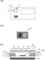
- figure 1 shows a schematic representation of a banknote 1 with a transparent window area 3 (shown in broken lines), which is provided with a security element 2 according to the invention in the form of a patch.
- the bank note 1 is based on a paper substrate which has a continuous gap in area 3 .
- the continuous gap is covered on at least one side of the paper substrate by the security element according to the invention, which is present as a laminate film.
- the paper substrate can optionally be provided with an additional transparent film.
- the additional transparent film can, for example, cover at least the area of the continuous recess.
- the banknote shown has the denomination "20" produced by printing in the lower left area.
- the figure 2 shows a security element 2 according to the invention according to a first embodiment in plan view.
- the security element 2 is semi-transparent in the shaded area, the viewer perceives this area when viewed in incident light in the form of a gold-colored metallization, when viewed in transmitted light the viewer perceives this area in a blue hue.
- the security element 2 is opaque, metallic, both when viewed in reflected light and when viewed in transmitted light.
- the security element 2 is transparent in the white area (see the number "0").
- the semi-transparent areas are in the figure 3 with the letter "A” and form the in the figure 2 shaded background surrounding the number "20".
- the central area of the embossing varnish 6 is provided with an opaque, reflective Al layer.
- the opaque, metallic area is in the figure 3 with provided with the letter “C” and forms the in the figure 2 shown digit "2".
- the transparent areas are in the figure 3 denoted by the letter "B” and form the in the figure 2 shown digit "0".
- the security element shown in the form of a laminate film is applied to the paper substrate of banknote 1 by means of an adhesive layer 11, in particular a heat-seal lacquer layer, so that recess 3 in the banknote is closed on one side by the security element and the viewer in the window area of the banknote can see the optical reflected light and can perceive transmitted light effects particularly well.
- the adhesive layer 11 can optionally be arranged over an optional primer layer 10 .
- the security element shows, for example, interesting three-dimensional warping effects in the areas “A” and/or “B”.
- the figure 5 shows a detail of a security element according to the invention according to a third embodiment, which is based on the first embodiment according to FIG figure 3 is ajar, in cross-sectional view.
- the micro- or nanostructure of the embossing lacquer layer 5 and the semi-transparent thin-film elements (with the layers 6, 7 and 8) that adapt to the relief of the embossing lacquer layer 5 on the one hand and the opaque, metallic Al layer 9 on the other hand are highlighted in the drawing.
- the figure 4 shows a detail of a security element according to the invention according to a second embodiment in a cross-sectional view. That in the figure 4 security element shown is located also like those in the Figures 3 and 5 shown security elements in the form of a laminate film and is suitable for covering the recess 3 in the figure 1 shown banknote 1.
- the security element shown contains a carrier 4 in the form of a transparent plastic film, for example a PET film. Above the carrier 4 there is an embossing lacquer 5 which is provided with a relief structure in the form of a microstructure or nanostructure.
- the embossing varnish 5 there are semi-transparent thin-film elements on the left side, on the right-hand side and in the central area, which give a viewer a different color impression when viewed in incident light and when viewed in transmitted light.
- Such a thin-film element appears gold in reflected light and blue in transmitted light.
- Certain areas of the left and right semi-transparent thin-film elements additionally have a reflective Al layer 12 and in this way form opaque, metallic areas.
- the semi-transparent thin-film elements (each containing the layers 6, 7 and 8) and the opaque, metallic layer 12 are covered by the protective lacquer 10.
- an ink acceptance layer or print acceptance layer (not shown in the figure) can be arranged above the protective lacquer 10 so that the security element can also be printed with ink.
- the security element shown in the form of a laminate film is applied to the paper substrate of the banknote 1 by means of an adhesive layer 11, in particular a heat-seal lacquer layer, so that the recess 3 of the banknote is one-sided from the security element is closed and the viewer in the window area of the banknote can perceive the optical incident and transmitted light effects particularly well.
- the security element shown appears metallic and opaque (eg silver) to the observer in the areas "C” and gold-colored in the semi-transparent areas "A” when viewed in reflected light and in a blue hue when viewed in transmitted light.
- the "B" areas represent the transparent areas.
- the figure 6 shows a security element not according to the invention according to a fourth example (comparative example) in plan view.
- the fourth example is in connection with the Figures 1 to 4 described embodiment based.
- security element shown takes the viewer in the case of figure 6 the numeral "2" is golden when viewed in reflected light and true in blue when viewed in transmitted light, ie, the numeral "2" is formed in the shape of a semitransparent region, eg, by means of a semitransparent Al/SiO 2 /Al thin film element.
- the digit "0" is formed in the shape of a transparent area.
- the background surrounding the digits "2" and “0” is in the form of an opaque, metallic surface, in the example in the form of a reflective Al layer.
- the figure 7 shows a schematic representation of a bank note 13 with a security element 14 according to the invention in the form of a security thread or security strip.
- Banknote 13 is a plastic banknote and is based on a polymer substrate.
- the security element 14 was formed in the form of a transfer foil (ie with a detachable carrier substrate) before being applied to the polymer substrate of the bank note 13 .
- the figure 8 shows the section of a security element 14 according to the invention according to a fifth exemplary embodiment in plan view.
- the security element 14 is semi-transparent in the shaded area, the viewer perceives this area when viewed in incident light in the form of a gold-colored metallization, when viewed in transmitted light the viewer perceives this area in a blue hue.
- the security element 14 In the black area (see the black numbers "20" on the left and right), the security element 14 is opaque, metallic, both when viewed in reflected light and when viewed in transmitted light.
- the white area see the middle white number "20"
- the security element 2 is transparent.
- the semi-transparent areas are in the figure 9 with the letter "A” and form the in the figure 8 shaded background surrounding the numbers "20".
- the central area of the embossing varnish 6 is provided with an opaque, reflective Al layer.
- the opaque, metallic area is in the figure 9 provided with the letter “C” and forms the in the figure 8 black numbers "20" shown left and right.
- the transparent areas are in the figure 9 denoted by the letter "B” and form the in the figure 8 shown middle white number "20".
- the security element shown in the form of a transfer film is applied to the polymer substrate of the banknote 13 by means of an adhesive layer 11, in particular a heat-sealing lacquer layer. After application to the polymer substrate, the temporary carrier 4 is detached from the security element applied to the bank note. In this way, the layer thickness of the bank note 14 in the area of the security element 14 is not too high.
- the figure 10 shows a security element not according to the invention according to a sixth example (comparative example) in plan view.
- the sixth example is in connection with the Figures 7 to 9 described embodiment based.
- security element shown takes the viewer in the case of figure 10 the left and
- the shaded numbers "20" shown on the right are gold-colored when viewed in incident light and blue when viewed in transmitted light, ie the shaded numbers "20" are each formed in the shape of a semi-transparent area, e.g. by means of a semi-transparent Al/SiO 2 /Al thin film element.
- the middle white number "20" is formed in the shape of a transparent area.
- the background surrounding the numbers "20” is in the form of an opaque, metallic surface, in the example in the form of a reflective Al layer.
- FIG. 11 describe a seventh example (comparative example) that is related to the Figures 7 to 9 is based on the exemplary embodiment described, in which the viewer sees the numbers "20" shown on the left and right, but not when viewing in reflected light (see figure 11 ), but only when viewed in transmitted light (see the figure 12 ) can recognize.
- the seventh example is also in the figure 9
- the layer structure shown is used, with the central region of the embossing lacquer 5 not being provided with an opaque, reflective, silver Al layer, but with an opaque, reflective, gold-colored layer (eg an Au layer or a Cu layer).
- This opaque, metallic, gold-colored area forms in the Figures 11 and 12 the black background.
- the numbers "20" shown on the left and right are each based on a semi-transparent thin film which is gold-colored when viewed in incident light and bluish when viewed in transmitted light. Therefore, the viewer can see the two numbers shown on the left and right "20" when viewed in reflected light (see the figure 11 ) not perceive, but only when viewed in transmitted light (see the figure 12 ).
- the in the Figures 11 and 12 The middle number "20" shown is in the form of a transparent area (see the area "B" in Fig figure 9 ) educated.
- a silver Al layer can be used and for the semi-transparent thin layer (see layers 6, 7 and 8 in the figure 9 ) an Al/SiO 2 /Al layer structure or an Al/SiO 2 /Al layer structure which is silver when viewed in reflected light and violet when viewed in transmitted light.
Claims (19)
- Élément de sécurité (2, 14) pour la protection de documents de valeur (1, 13) avec un support (4), une structure de couches agencée sur le support (4) par l'intermédiaire d'une couche de vernis d'estampage (5) et une couche adhésive (11) appropriée pour le collage de l'élément de sécurité (2, 14) avec un objet de valeur (1, 13), la structure de couches présentant des zones métalliques opaques, des zones semi-transparentes qui donnent à un observateur une impression de couleur différente lorsqu'elles sont observées en lumière incidente et lorsqu'elles sont observées en lumière transmise, et des zones transparentes, aussi bien les zones transparentes que les zones métalliques opaques étant formées respectivement sous la forme de motifs, de caractères ou d'un codage et les zones semi-transparentes représentant un arrière-plan, la couche de vernis d'estampage (5) étant pourvue d'une structure en relief estampée,
caractérisé en ce que
la couche de vernis d'estampage (5) avec une structure en relief estampée présente la même structure en relief dans les zones formées respectivement sous la forme de motifs, de caractères ou d'un codage, et présente une autre structure en relief dans les zones représentant un arrière-plan. - Élément de sécurité selon la revendication 1, dans lequel les zones métalliques opaques sont basées sur une métallisation pouvant être obtenue par évaporation ou peuvent être obtenues par impression et sont basées sur des pigments métalliques en forme de plaquettes.
- Élément de sécurité selon l'une quelconque des revendications 1 ou 2, dans lequel les zones semi-transparentes, qui donnent à un observateur une impression de couleur différente lorsqu'elles sont observées en lumière incidente et lorsqu'elles sont observées en lumière transmise, sont basées sur un élément à couche mince présentant deux couches de miroir semi-transparentes et une couche d'espacement diélectrique agencée entre les deux couches de miroir.
- Élément de sécurité selon l'une quelconque des revendications 1 ou 2, dans lequel les zones semi-transparentes qui donnent à un observateur une impression de couleur différente lorsqu'elles sont observées en lumière incidente et lorsqu'elles sont observées en lumière transmise peuvent être obtenues par impression au moyen d'une composition de pigment à effet.
- Élément de sécurité selon l'une quelconque des revendications 1 à 4, dans lequel la structure en relief forme une structure diffractive, telle qu'un hologramme, un réseau holographique ou une structure de diffraction semblable à un hologramme, ou une structure achromatique, telle qu'une structure mate, ou un agencement de micromiroirs, ou un réseau blazé avec un profil de sillons en forme de dents de scie, ou un agencement de lentilles de Fresnel, ou une combinaison de deux ou plus des éléments précités.
- Élément de sécurité selon l'une quelconque des revendications 1 à 5, dans lequel la couche de vernis d'estampage avec une structure en relief estampée présente la même structure en relief dans les zones formées respectivement sous la forme de motifs, de caractères ou d'un codage et présente une autre structure en relief dans les zones représentant un arrière-plan, à savoir que la première structure en relief forme une structure diffractive et la deuxième structure en relief forme un agencement de micromiroirs.
- Élément de sécurité selon l'une quelconque des revendications 1 à 6, dans lequel les zones formées respectivement sous la forme de motifs, de caractères ou d'un codage sont agencées au moins partiellement en repérage exact les unes par rapport aux autres.
- Élément de sécurité selon l'une quelconque des revendications 1 à 7, dans lequel (i) l'impression de couleur des zones semi-transparentes lorsqu'elles sont observées en lumière incidente est identique à l'impression de couleur des zones métalliques opaques, et l'impression de couleur des zones semi-transparentes lorsqu'elles sont observées en lumière transmise est différente de l'impression de couleur des zones métalliques opaques, ou (ii) l'impression de couleur des zones semi-transparentes lorsqu'elles sont observées en lumière incidente et l'impression de couleur des zones semi-transparentes lorsqu'elles sont observées en lumière transmise sont différentes de l'impression de couleur des zones métalliques opaques.
- Élément de sécurité selon l'une quelconque des revendications 1 à 8, dans lequel la structure en relief estampée dans la couche de vernis d'estampage présente les zones transparentes, les zones métalliques opaques et les zones semi-transparentes dans trois zones partielles séparées.
- Élément de sécurité selon l'une quelconque des revendications 1 à 8, dans lequel la structure en relief estampée dans la couche de vernis d'estampage présente les zones transparentes et les zones semi-transparentes dans deux zones partielles séparées et une partie des zones semi-transparentes est en outre pourvue d'une métallisation pouvant être obtenue par évaporation ou est imprimée avec des pigments métalliques en forme de plaquettes pour former ainsi les zones métalliques opaques.
- Élément de sécurité selon l'une quelconque des revendications 1 à 10, dans lequel la séquence de couches de l'élément de sécurité est la suivante :a) support ;b) couche de vernis d'estampage avec structure en relief estampée ;c) structure de couches qui présente des zones métalliques opaques, des zones semi-transparentes qui donnent à l'observateur une impression de couleur différente lorsqu'elles sont observées en lumière incidente et lorsqu'elles sont observées en lumière transmise, et des zones transparentes ;d) couche adhésive appropriée pour le collage de l'élément de sécurité avec un objet de valeur.
- Élément de sécurité selon l'une quelconque des revendications 1 à 10, dans lequel la séquence de couches de l'élément de sécurité est la suivante :a) couche adhésive appropriée pour le collage de l'élément de sécurité avec un objet de valeur ;b) support ;c) couche de vernis d'estampage avec structure en relief estampée ;d) structure de couches qui présente des zones métalliques opaques, des zones semi-transparentes qui donnent à l'observateur une impression de couleur différente lorsqu'elles sont observées en lumière incidente et lorsqu'elles sont observées en lumière transmise, et des zones transparentes ;e) couche de protection, notamment couche de protection à base d'un vernis protecteur.
- Élément de sécurité selon l'une quelconque des revendications 1 à 12, dans lequel l'élément de sécurité est un ruban de sécurité, une bande de sécurité, un patch ou une étiquette à appliquer sur un papier de sécurité, un document de valeur ou similaire.
- Support de données (1, 13) avec un élément de sécurité (2, 14) selon l'une quelconque des revendications 1 à 13.
- Support de données selon la revendication 14, dans lequel l'élément de sécurité est agencé dans une zone de fenêtre transparente du support de données.
- Support de données selon la revendication 14 ou 15, dans lequel le support de données est un document de valeur, tel qu'un billet de banque, notamment un billet de banque en papier, un billet de banque en polymère ou un billet de banque en film composite, ou une carte d'identité.
- Procédé de fabrication d'un élément de sécurité (2, 14) pour la protection de documents de valeur (1, 13), à savoir d'un élément de sécurité (2, 14) selon l'une quelconque des revendications 1 à 13, avec un support (4), une structure de couches agencée sur le support (4) par l'intermédiaire d'une couche de vernis d'estampage (5) et une couche adhésive appropriée pour le collage de l'élément de sécurité (2, 14) avec un objet de valeur (1, 13), la structure de couches comprenant des zones métalliques opaques, des zones semi-transparentes qui donnent à un observateur une impression de couleur différente lorsqu'elles sont observées en lumière incidente et lorsqu'elles sont observées en lumière transmise, et des zones transparentes, le procédé comprenant les étapes suivantes :- l'étape de fourniture d'un substrat de support (4) sur lequel est appliquée une couche de vernis d'estampage (5) ;- l'étape d'impression d'une encre lavable amovible dans les zones à l'extérieur des zones métalliques opaques à produire ;- l'étape d'application d'une métallisation, p. ex. une couche réfléchissante d'Al, de Cr, de Cu ou d'Au, notamment par évaporation, une couche d'Al étant préférée ;- l'étape d'élimination par lavage de l'encre lavable amovible conjointement avec la métallisation se trouvant au-dessus de l'encre lavable au moyen d'un solvant, de telle sorte que des zones métalliques opaques restent sur la couche de vernis d'estampage ;- l'étape d'impression d'une encre lavable amovible dans les zones à l'extérieur des zones semi-transparentes à produire ;- l'étape de production d'une structure multicouche avec deux couches métalliques semi-transparentes et une couche diélectrique agencée entre les deux couches métalliques semi-transparentes, notamment par évaporation ;- l'étape d'élimination par lavage de l'encre lavable amovible conjointement avec la structure multicouche se trouvant au-dessus de l'encre lavable, de telle sorte qu'en plus des zones métalliques opaques, des zones semi-transparentes restent également sur la couche de vernis d'estampage (5) et que des zones transparentes soient formées entre les zones métalliques opaques et les zones semi-transparentes ;- facultativement l'étape d'application d'une couche primaire facultative ; et- l'étape d'application d'une couche adhésive (11), p. ex. d'une couche de vernis thermosoudable.
- Procédé de fabrication d'un élément de sécurité (2, 14) pour la protection de documents de valeur (1, 13), à savoir d'un élément de sécurité (2, 14) selon l'une quelconque des revendications 1 à 13, avec un support (4), une structure de couches agencée sur le support (4) par l'intermédiaire d'une couche de vernis d'estampage (5) et une couche adhésive (11) appropriée pour le collage de l'élément de sécurité (2, 14) avec un objet de valeur (1, 13), la structure de couches présentant des zones métalliques opaques, des zones semi-transparentes qui donnent à un observateur une impression de couleur différente lorsqu'elles sont observées en lumière incidente et lorsqu'elles sont observées en lumière transmise, et des zones transparentes, comprenant les étapes suivantes :- l'étape de fourniture d'un substrat de support (4) sur lequel est appliquée une couche de vernis d'estampage (5) ;- l'étape de production par impression de zones métalliques opaques sur la couche de vernis d'estampage (5) au moyen d'une encre d'impression à base de pigments métalliques en forme de plaquettes ;- l'étape d'impression d'une encre lavable amovible dans les zones à l'extérieur des zones semi-transparentes à produire ;- l'étape de production d'une structure multicouche avec deux couches métalliques semi-transparentes et une couche diélectrique agencée entre les deux couches métalliques semi-transparentes, notamment par évaporation ;- l'étape d'élimination par lavage de l'encre lavable amovible conjointement avec la structure multicouche se trouvant au-dessus de l'encre lavable, de telle sorte qu'en plus des zones métalliques opaques, des zones semi-transparentes restent également sur la couche de vernis d'estampage (5) et que des zones transparentes soient formées entre les zones métalliques opaques et les zones semi-transparentes ;- facultativement l'étape d'application d'une couche primaire facultative ; et- l'étape d'application d'une couche adhésive (11), p. ex. d'une couche de vernis thermosoudable.
- Procédé de fabrication d'un élément de sécurité (2, 14) pour la protection de documents de valeur (1, 13), à savoir d'un élément de sécurité (2, 14) selon l'une quelconque des revendications 1 à 13, avec un support (4), une structure de couches agencée sur le support (4) par l'intermédiaire d'une couche de vernis d'estampage (5) et une couche adhésive (11) appropriée pour le collage de l'élément de sécurité (2, 14) avec un objet de valeur (1, 13), la structure de couches présentant des zones métalliques opaques, des zones semi-transparentes qui donnent à un observateur une impression de couleur différente lorsqu'elles sont observées en lumière incidente et lorsqu'elles sont observées en lumière transmise, et des zones transparentes, comprenant les étapes suivantes :- l'étape de fourniture d'un substrat de support (4) sur lequel est appliquée une couche de vernis d'estampage (5) ;- l'étape d'impression d'une encre lavable amovible dans les zones à l'extérieur des zones semi-transparentes à produire ;- l'étape de production d'une structure multicouche avec deux couches métalliques semi-transparentes et une couche diélectrique agencée entre les deux couches métalliques semi-transparentes, notamment par évaporation ;- l'étape d'élimination par lavage de l'encre lavable amovible conjointement avec la structure multicouche se trouvant au-dessus de l'encre lavable, de telle sorte que des zones semi-transparentes restent sur la couche de vernis d'estampage (5) ;- l'étape d'impression d'une encre lavable amovible dans les zones à l'extérieur des zones métalliques opaques à produire ;- l'étape d'application d'une métallisation, p. ex. d'une couche réfléchissante d'Al, de Cr, de Cu ou d'Au par évaporation, une couche d'Al étant préférée, l'étape état effectuée de telle sorte qu'une partie des zones semi-transparentes est en outre pourvue d'une métallisation pouvant être obtenue par évaporation, afin de former ainsi les zones métalliques opaques ;- l'étape d'élimination par lavage de l'encre lavable amovible conjointement avec la métallisation se trouvant au-dessus de l'encre lavable ;- facultativement l'étape d'application d'une couche primaire facultative ; et- l'étape d'application d'une couche adhésive (11), p. ex. d'une couche de vernis thermosoudable.
Priority Applications (1)
| Application Number | Priority Date | Filing Date | Title |
|---|---|---|---|
| EP23020047.9A EP4219182A3 (fr) | 2018-04-13 | 2019-04-08 | Élément de sécurité, son procédé de fabrication et support de données équipé de l'élément de sécurité |
Applications Claiming Priority (2)
| Application Number | Priority Date | Filing Date | Title |
|---|---|---|---|
| DE102018003030.0A DE102018003030A1 (de) | 2018-04-13 | 2018-04-13 | Sicherheitselement, Verfahren zum Herstellen desselben und mit dem Sicherheitselement ausgestatteter Datenträger |
| PCT/EP2019/000112 WO2019197054A1 (fr) | 2018-04-13 | 2019-04-08 | Élément de sécurité, procédé de fabrication de l'élément de sécurité, et support de données équipé de cet élément de sécurité |
Related Child Applications (2)
| Application Number | Title | Priority Date | Filing Date |
|---|---|---|---|
| EP23020047.9A Division EP4219182A3 (fr) | 2018-04-13 | 2019-04-08 | Élément de sécurité, son procédé de fabrication et support de données équipé de l'élément de sécurité |
| EP23020047.9A Division-Into EP4219182A3 (fr) | 2018-04-13 | 2019-04-08 | Élément de sécurité, son procédé de fabrication et support de données équipé de l'élément de sécurité |
Publications (2)
| Publication Number | Publication Date |
|---|---|
| EP3774375A1 EP3774375A1 (fr) | 2021-02-17 |
| EP3774375B1 true EP3774375B1 (fr) | 2023-06-21 |
Family
ID=66223655
Family Applications (2)
| Application Number | Title | Priority Date | Filing Date |
|---|---|---|---|
| EP23020047.9A Pending EP4219182A3 (fr) | 2018-04-13 | 2019-04-08 | Élément de sécurité, son procédé de fabrication et support de données équipé de l'élément de sécurité |
| EP19718247.0A Active EP3774375B1 (fr) | 2018-04-13 | 2019-04-08 | Élément de sécurité, procédé de fabrication de l'élément de sécurité, et support de données équipé de cet élément de sécurité |
Family Applications Before (1)
| Application Number | Title | Priority Date | Filing Date |
|---|---|---|---|
| EP23020047.9A Pending EP4219182A3 (fr) | 2018-04-13 | 2019-04-08 | Élément de sécurité, son procédé de fabrication et support de données équipé de l'élément de sécurité |
Country Status (4)
| Country | Link |
|---|---|
| EP (2) | EP4219182A3 (fr) |
| CN (1) | CN111867851B (fr) |
| DE (1) | DE102018003030A1 (fr) |
| WO (1) | WO2019197054A1 (fr) |
Families Citing this family (2)
| Publication number | Priority date | Publication date | Assignee | Title |
|---|---|---|---|---|
| DE102020007728A1 (de) | 2020-12-17 | 2022-06-23 | Giesecke+Devrient Currency Technology Gmbh | Datenträger mit Verbundsubstrat mit einem in einem Durchsichtsbereich angeordneten Sicherheitselement |
| DE102022002353A1 (de) * | 2022-06-29 | 2024-01-04 | Giesecke+Devrient Currency Technology Gmbh | Sicherheitselement, Wertdokument und Verfahren zum Herstellen desselben |
Family Cites Families (16)
| Publication number | Priority date | Publication date | Assignee | Title |
|---|---|---|---|---|
| DE10150293B4 (de) * | 2001-10-12 | 2005-05-12 | Ovd Kinegram Ag | Sicherheitselement |
| JP4660187B2 (ja) * | 2002-05-14 | 2011-03-30 | レオナード クルツ シュティフトゥング ウント コンパニー カーゲー | 薄膜層配列を備えた光学的に変化する素子 |
| GB0326576D0 (en) | 2003-11-14 | 2003-12-17 | Printetch Ltd | Printing composition |
| DE102008013167A1 (de) * | 2008-03-07 | 2009-09-10 | Giesecke & Devrient Gmbh | Sicherheitselement und Verfahren zu seiner Herstellung |
| EP2379650B1 (fr) | 2008-12-19 | 2017-11-29 | Basf Se | Flocons d'aluminium minces |
| DE102009048145A1 (de) * | 2009-10-02 | 2011-04-07 | Giesecke & Devrient Gmbh | Datenträger mit Fenster |
| EP3287497B1 (fr) | 2009-11-27 | 2022-08-31 | Basf Se | Compositions de revêtement pour éléments de sécurité et hologrammes |
| DE102009058243A1 (de) | 2009-12-14 | 2011-06-16 | Giesecke & Devrient Gmbh | Dünnschichtelement mit Mehrschichtstruktur |
| US20150158323A1 (en) | 2012-06-14 | 2015-06-11 | Basf Se | Method for manufacturing security elements and holograms |
| DE102013113283A1 (de) * | 2013-11-29 | 2015-06-03 | Leonhard Kurz Stiftung & Co. Kg | Mehrschichtkörper und Verfahren zu dessen Herstellung |
| CN105793058B (zh) * | 2013-12-11 | 2018-07-10 | 锡克拜控股有限公司 | 安全线或条及其制造方法和用途、安全文件及其制造方法 |
| DE102014001842A1 (de) * | 2014-02-11 | 2015-08-13 | Giesecke & Devrient Gmbh | Verfahren zum Herstellen eines Sicherheitselements mit Negativschrift und daraus erhältliches Sicherheitselement |
| DE102014018204A1 (de) * | 2014-12-09 | 2016-06-09 | Giesecke & Devrient Gmbh | Sicherheitselement, Verfahren zum Herstellen desselben und mit dem Sicherheitselement ausgestatteter Datenträger |
| DE102014019088A1 (de) * | 2014-12-18 | 2016-06-23 | Giesecke & Devrient Gmbh | Optisch variables Durchsichtssicherheitselement |
| DE102015010744A1 (de) * | 2015-08-17 | 2017-02-23 | Giesecke & Devrient Gmbh | Sicherheitselement, Verfahren zum Herstellen desselben und mit dem Sicherheitselement ausgestatteter Datenträger |
| CN105479974B (zh) * | 2015-12-01 | 2018-07-13 | 中钞特种防伪科技有限公司 | 一种光学防伪元件及使用该光学防伪元件的光学防伪产品 |
-
2018
- 2018-04-13 DE DE102018003030.0A patent/DE102018003030A1/de not_active Withdrawn
-
2019
- 2019-04-08 EP EP23020047.9A patent/EP4219182A3/fr active Pending
- 2019-04-08 CN CN201980019152.7A patent/CN111867851B/zh active Active
- 2019-04-08 WO PCT/EP2019/000112 patent/WO2019197054A1/fr active Application Filing
- 2019-04-08 EP EP19718247.0A patent/EP3774375B1/fr active Active
Also Published As
| Publication number | Publication date |
|---|---|
| CN111867851B (zh) | 2022-03-15 |
| CN111867851A (zh) | 2020-10-30 |
| EP4219182A3 (fr) | 2023-11-01 |
| EP4219182A2 (fr) | 2023-08-02 |
| WO2019197054A1 (fr) | 2019-10-17 |
| DE102018003030A1 (de) | 2019-10-17 |
| EP3774375A1 (fr) | 2021-02-17 |
Similar Documents
| Publication | Publication Date | Title |
|---|---|---|
| EP3337675B1 (fr) | Élément de sécurité, procédé de production de ce dernier et support de données équipé de l'élément de sécurité | |
| EP3230081B1 (fr) | Élément de sécurité, procédé de production de ce dernier et support de données équipé de l'élément de sécurité | |
| EP3374197B1 (fr) | Élément de sécurité, procédé de fabrication de l'élément de sécurité, et support de données équipé de cet élément de sécurité | |
| EP1827864B1 (fr) | Element de securite comportant une couche a variation optique et son procede de production | |
| EP2310211B1 (fr) | Élément de sécurité et son procédé de fabrication | |
| EP3565722B1 (fr) | Document de valeur | |
| EP3260302B1 (fr) | Élément de sécurité optique variable | |
| EP3643511B1 (fr) | Élément de sécurité et support de données équipé de l'élément de sécurité | |
| EP2219168B1 (fr) | Elément de sécurité à transmission | |
| DE102008013167A1 (de) | Sicherheitselement und Verfahren zu seiner Herstellung | |
| DE102015015733A1 (de) | Sicherheitselement und mit demselben ausgestatteter Datenträger | |
| EP3774375B1 (fr) | Élément de sécurité, procédé de fabrication de l'élément de sécurité, et support de données équipé de cet élément de sécurité | |
| DE102016007064A1 (de) | Sicherheitselement, Wertdokumentsubstrat, mit demselben ausgestattetes Wertdokument und Herstellungsverfahren | |
| EP3212429B1 (fr) | Élément de sécurité pourvu d'un élément à couche mince à effet interférentiel | |
| WO2020088791A1 (fr) | Élément de sécurité et support de données équipé de l'élément de sécurité | |
| WO2017194189A1 (fr) | Élément de sécurité et support de données | |
| DE102016010616A1 (de) | Sicherheitselement mit mehreren Sicherheitsmerkmalen | |
| DE102014016028A1 (de) | Sicherheitselement mit farbkippendem Dünnschichtelement | |
| EP3414100B1 (fr) | Support de données | |
| EP3219508B1 (fr) | Élément de sécurité et support de données | |
| EP3939801B1 (fr) | Document de valeur | |
| DE102015015731A1 (de) | Sicherheitselement und mit demselben ausgestatteter Datenträger |
Legal Events
| Date | Code | Title | Description |
|---|---|---|---|
| STAA | Information on the status of an ep patent application or granted ep patent |
Free format text: STATUS: UNKNOWN |
|
| STAA | Information on the status of an ep patent application or granted ep patent |
Free format text: STATUS: THE INTERNATIONAL PUBLICATION HAS BEEN MADE |
|
| PUAI | Public reference made under article 153(3) epc to a published international application that has entered the european phase |
Free format text: ORIGINAL CODE: 0009012 |
|
| STAA | Information on the status of an ep patent application or granted ep patent |
Free format text: STATUS: REQUEST FOR EXAMINATION WAS MADE |
|
| 17P | Request for examination filed |
Effective date: 20201113 |
|
| AK | Designated contracting states |
Kind code of ref document: A1 Designated state(s): AL AT BE BG CH CY CZ DE DK EE ES FI FR GB GR HR HU IE IS IT LI LT LU LV MC MK MT NL NO PL PT RO RS SE SI SK SM TR |
|
| AX | Request for extension of the european patent |
Extension state: BA ME |
|
| DAV | Request for validation of the european patent (deleted) | ||
| DAX | Request for extension of the european patent (deleted) | ||
| GRAP | Despatch of communication of intention to grant a patent |
Free format text: ORIGINAL CODE: EPIDOSNIGR1 |
|
| STAA | Information on the status of an ep patent application or granted ep patent |
Free format text: STATUS: GRANT OF PATENT IS INTENDED |
|
| INTG | Intention to grant announced |
Effective date: 20230110 |
|
| RAP3 | Party data changed (applicant data changed or rights of an application transferred) |
Owner name: GIESECKE+DEVRIENT CURRENCY TECHNOLOGY GMBH |
|
| GRAS | Grant fee paid |
Free format text: ORIGINAL CODE: EPIDOSNIGR3 |
|
| GRAA | (expected) grant |
Free format text: ORIGINAL CODE: 0009210 |
|
| STAA | Information on the status of an ep patent application or granted ep patent |
Free format text: STATUS: THE PATENT HAS BEEN GRANTED |
|
| AK | Designated contracting states |
Kind code of ref document: B1 Designated state(s): AL AT BE BG CH CY CZ DE DK EE ES FI FR GB GR HR HU IE IS IT LI LT LU LV MC MK MT NL NO PL PT RO RS SE SI SK SM TR |
|
| P01 | Opt-out of the competence of the unified patent court (upc) registered |
Effective date: 20230519 |
|
| REG | Reference to a national code |
Ref country code: CH Ref legal event code: EP |
|
| REG | Reference to a national code |
Ref country code: DE Ref legal event code: R096 Ref document number: 502019008263 Country of ref document: DE |
|
| REG | Reference to a national code |
Ref country code: AT Ref legal event code: REF Ref document number: 1580674 Country of ref document: AT Kind code of ref document: T Effective date: 20230715 |
|
| REG | Reference to a national code |
Ref country code: IE Ref legal event code: FG4D Free format text: LANGUAGE OF EP DOCUMENT: GERMAN |
|
| REG | Reference to a national code |
Ref country code: LT Ref legal event code: MG9D |
|
| REG | Reference to a national code |
Ref country code: NL Ref legal event code: MP Effective date: 20230621 |
|
| PG25 | Lapsed in a contracting state [announced via postgrant information from national office to epo] |
Ref country code: SE Free format text: LAPSE BECAUSE OF FAILURE TO SUBMIT A TRANSLATION OF THE DESCRIPTION OR TO PAY THE FEE WITHIN THE PRESCRIBED TIME-LIMIT Effective date: 20230621 Ref country code: NO Free format text: LAPSE BECAUSE OF FAILURE TO SUBMIT A TRANSLATION OF THE DESCRIPTION OR TO PAY THE FEE WITHIN THE PRESCRIBED TIME-LIMIT Effective date: 20230921 |
|
| PG25 | Lapsed in a contracting state [announced via postgrant information from national office to epo] |
Ref country code: RS Free format text: LAPSE BECAUSE OF FAILURE TO SUBMIT A TRANSLATION OF THE DESCRIPTION OR TO PAY THE FEE WITHIN THE PRESCRIBED TIME-LIMIT Effective date: 20230621 Ref country code: NL Free format text: LAPSE BECAUSE OF FAILURE TO SUBMIT A TRANSLATION OF THE DESCRIPTION OR TO PAY THE FEE WITHIN THE PRESCRIBED TIME-LIMIT Effective date: 20230621 Ref country code: LV Free format text: LAPSE BECAUSE OF FAILURE TO SUBMIT A TRANSLATION OF THE DESCRIPTION OR TO PAY THE FEE WITHIN THE PRESCRIBED TIME-LIMIT Effective date: 20230621 Ref country code: LT Free format text: LAPSE BECAUSE OF FAILURE TO SUBMIT A TRANSLATION OF THE DESCRIPTION OR TO PAY THE FEE WITHIN THE PRESCRIBED TIME-LIMIT Effective date: 20230621 Ref country code: HR Free format text: LAPSE BECAUSE OF FAILURE TO SUBMIT A TRANSLATION OF THE DESCRIPTION OR TO PAY THE FEE WITHIN THE PRESCRIBED TIME-LIMIT Effective date: 20230621 Ref country code: GR Free format text: LAPSE BECAUSE OF FAILURE TO SUBMIT A TRANSLATION OF THE DESCRIPTION OR TO PAY THE FEE WITHIN THE PRESCRIBED TIME-LIMIT Effective date: 20230922 |
|
| PG25 | Lapsed in a contracting state [announced via postgrant information from national office to epo] |
Ref country code: FI Free format text: LAPSE BECAUSE OF FAILURE TO SUBMIT A TRANSLATION OF THE DESCRIPTION OR TO PAY THE FEE WITHIN THE PRESCRIBED TIME-LIMIT Effective date: 20230621 |
|
| PG25 | Lapsed in a contracting state [announced via postgrant information from national office to epo] |
Ref country code: SK Free format text: LAPSE BECAUSE OF FAILURE TO SUBMIT A TRANSLATION OF THE DESCRIPTION OR TO PAY THE FEE WITHIN THE PRESCRIBED TIME-LIMIT Effective date: 20230621 |
|
| PG25 | Lapsed in a contracting state [announced via postgrant information from national office to epo] |
Ref country code: ES Free format text: LAPSE BECAUSE OF FAILURE TO SUBMIT A TRANSLATION OF THE DESCRIPTION OR TO PAY THE FEE WITHIN THE PRESCRIBED TIME-LIMIT Effective date: 20230621 |
|
| PG25 | Lapsed in a contracting state [announced via postgrant information from national office to epo] |
Ref country code: IS Free format text: LAPSE BECAUSE OF FAILURE TO SUBMIT A TRANSLATION OF THE DESCRIPTION OR TO PAY THE FEE WITHIN THE PRESCRIBED TIME-LIMIT Effective date: 20231021 |
|
| PG25 | Lapsed in a contracting state [announced via postgrant information from national office to epo] |
Ref country code: SM Free format text: LAPSE BECAUSE OF FAILURE TO SUBMIT A TRANSLATION OF THE DESCRIPTION OR TO PAY THE FEE WITHIN THE PRESCRIBED TIME-LIMIT Effective date: 20230621 Ref country code: SK Free format text: LAPSE BECAUSE OF FAILURE TO SUBMIT A TRANSLATION OF THE DESCRIPTION OR TO PAY THE FEE WITHIN THE PRESCRIBED TIME-LIMIT Effective date: 20230621 Ref country code: RO Free format text: LAPSE BECAUSE OF FAILURE TO SUBMIT A TRANSLATION OF THE DESCRIPTION OR TO PAY THE FEE WITHIN THE PRESCRIBED TIME-LIMIT Effective date: 20230621 Ref country code: PT Free format text: LAPSE BECAUSE OF FAILURE TO SUBMIT A TRANSLATION OF THE DESCRIPTION OR TO PAY THE FEE WITHIN THE PRESCRIBED TIME-LIMIT Effective date: 20231023 Ref country code: IS Free format text: LAPSE BECAUSE OF FAILURE TO SUBMIT A TRANSLATION OF THE DESCRIPTION OR TO PAY THE FEE WITHIN THE PRESCRIBED TIME-LIMIT Effective date: 20231021 Ref country code: ES Free format text: LAPSE BECAUSE OF FAILURE TO SUBMIT A TRANSLATION OF THE DESCRIPTION OR TO PAY THE FEE WITHIN THE PRESCRIBED TIME-LIMIT Effective date: 20230621 Ref country code: EE Free format text: LAPSE BECAUSE OF FAILURE TO SUBMIT A TRANSLATION OF THE DESCRIPTION OR TO PAY THE FEE WITHIN THE PRESCRIBED TIME-LIMIT Effective date: 20230621 Ref country code: CZ Free format text: LAPSE BECAUSE OF FAILURE TO SUBMIT A TRANSLATION OF THE DESCRIPTION OR TO PAY THE FEE WITHIN THE PRESCRIBED TIME-LIMIT Effective date: 20230621 |
|
| PG25 | Lapsed in a contracting state [announced via postgrant information from national office to epo] |
Ref country code: PL Free format text: LAPSE BECAUSE OF FAILURE TO SUBMIT A TRANSLATION OF THE DESCRIPTION OR TO PAY THE FEE WITHIN THE PRESCRIBED TIME-LIMIT Effective date: 20230621 |