EP3774375B1 - Security element, method for producing same, and data carrier equipped with the security element - Google Patents
Security element, method for producing same, and data carrier equipped with the security element Download PDFInfo
- Publication number
- EP3774375B1 EP3774375B1 EP19718247.0A EP19718247A EP3774375B1 EP 3774375 B1 EP3774375 B1 EP 3774375B1 EP 19718247 A EP19718247 A EP 19718247A EP 3774375 B1 EP3774375 B1 EP 3774375B1
- Authority
- EP
- European Patent Office
- Prior art keywords
- regions
- layer
- security element
- semitransparent
- metallic
- Prior art date
- Legal status (The legal status is an assumption and is not a legal conclusion. Google has not performed a legal analysis and makes no representation as to the accuracy of the status listed.)
- Active
Links
- 238000004519 manufacturing process Methods 0.000 title description 9
- 239000010410 layer Substances 0.000 claims description 224
- 239000004922 lacquer Substances 0.000 claims description 64
- 238000004049 embossing Methods 0.000 claims description 62
- 239000000758 substrate Substances 0.000 claims description 40
- 239000012790 adhesive layer Substances 0.000 claims description 24
- 229910052737 gold Inorganic materials 0.000 claims description 22
- 238000001465 metallisation Methods 0.000 claims description 21
- 239000010409 thin film Substances 0.000 claims description 18
- 238000007740 vapor deposition Methods 0.000 claims description 18
- 238000010276 construction Methods 0.000 claims description 17
- 239000000049 pigment Substances 0.000 claims description 17
- 238000005406 washing Methods 0.000 claims description 15
- 239000010408 film Substances 0.000 claims description 13
- 229910052751 metal Inorganic materials 0.000 claims description 11
- 239000002184 metal Substances 0.000 claims description 11
- 230000000694 effects Effects 0.000 claims description 10
- 229910052782 aluminium Inorganic materials 0.000 claims description 8
- 238000000034 method Methods 0.000 claims description 8
- 229910052802 copper Inorganic materials 0.000 claims description 7
- 125000006850 spacer group Chemical group 0.000 claims description 7
- 229910052804 chromium Inorganic materials 0.000 claims description 6
- 239000004920 heat-sealing lacquer Substances 0.000 claims description 4
- 239000000203 mixture Substances 0.000 claims description 3
- 230000001681 protective effect Effects 0.000 claims description 3
- 239000011241 protective layer Substances 0.000 claims description 3
- 239000002904 solvent Substances 0.000 claims description 3
- 229920000642 polymer Polymers 0.000 claims description 2
- 239000010931 gold Substances 0.000 description 21
- PCHJSUWPFVWCPO-UHFFFAOYSA-N gold Chemical compound [Au] PCHJSUWPFVWCPO-UHFFFAOYSA-N 0.000 description 17
- 229910004298 SiO 2 Inorganic materials 0.000 description 13
- 229910052709 silver Inorganic materials 0.000 description 13
- VYPSYNLAJGMNEJ-UHFFFAOYSA-N Silicium dioxide Chemical compound O=[Si]=O VYPSYNLAJGMNEJ-UHFFFAOYSA-N 0.000 description 12
- 229920000139 polyethylene terephthalate Polymers 0.000 description 12
- BQCADISMDOOEFD-UHFFFAOYSA-N Silver Chemical compound [Ag] BQCADISMDOOEFD-UHFFFAOYSA-N 0.000 description 11
- 239000004332 silver Substances 0.000 description 10
- 230000000052 comparative effect Effects 0.000 description 9
- 239000005020 polyethylene terephthalate Substances 0.000 description 9
- 244000172533 Viola sororia Species 0.000 description 8
- 239000011888 foil Substances 0.000 description 8
- 239000005001 laminate film Substances 0.000 description 8
- 229920000307 polymer substrate Polymers 0.000 description 8
- 239000002966 varnish Substances 0.000 description 8
- 238000012546 transfer Methods 0.000 description 7
- 238000004026 adhesive bonding Methods 0.000 description 6
- 229910052681 coesite Inorganic materials 0.000 description 6
- 239000010949 copper Substances 0.000 description 6
- 229910052906 cristobalite Inorganic materials 0.000 description 6
- 239000000377 silicon dioxide Substances 0.000 description 6
- 229910052682 stishovite Inorganic materials 0.000 description 6
- 229910052905 tridymite Inorganic materials 0.000 description 6
- 230000005540 biological transmission Effects 0.000 description 5
- 239000002131 composite material Substances 0.000 description 5
- 239000011651 chromium Substances 0.000 description 4
- 229920003023 plastic Polymers 0.000 description 4
- 229920002799 BoPET Polymers 0.000 description 3
- XEEYBQQBJWHFJM-UHFFFAOYSA-N Iron Chemical compound [Fe] XEEYBQQBJWHFJM-UHFFFAOYSA-N 0.000 description 3
- PXHVJJICTQNCMI-UHFFFAOYSA-N Nickel Chemical compound [Ni] PXHVJJICTQNCMI-UHFFFAOYSA-N 0.000 description 3
- 239000011230 binding agent Substances 0.000 description 3
- 239000011248 coating agent Substances 0.000 description 3
- 238000000576 coating method Methods 0.000 description 3
- 230000001419 dependent effect Effects 0.000 description 3
- 239000002086 nanomaterial Substances 0.000 description 3
- 230000003287 optical effect Effects 0.000 description 3
- 239000002985 plastic film Substances 0.000 description 3
- -1 polyethylene terephthalate Polymers 0.000 description 3
- RYGMFSIKBFXOCR-UHFFFAOYSA-N Copper Chemical compound [Cu] RYGMFSIKBFXOCR-UHFFFAOYSA-N 0.000 description 2
- QAOWNCQODCNURD-UHFFFAOYSA-N Sulfuric acid Chemical compound OS(O)(=O)=O QAOWNCQODCNURD-UHFFFAOYSA-N 0.000 description 2
- ZPUCINDJVBIVPJ-LJISPDSOSA-N cocaine Chemical compound O([C@H]1C[C@@H]2CC[C@@H](N2C)[C@H]1C(=O)OC)C(=O)C1=CC=CC=C1 ZPUCINDJVBIVPJ-LJISPDSOSA-N 0.000 description 2
- 239000003086 colorant Substances 0.000 description 2
- 229910001254 electrum Inorganic materials 0.000 description 2
- 239000010940 green gold Substances 0.000 description 2
- 229910052742 iron Inorganic materials 0.000 description 2
- 230000001795 light effect Effects 0.000 description 2
- 229910052759 nickel Inorganic materials 0.000 description 2
- 229910052723 transition metal Inorganic materials 0.000 description 2
- 150000003624 transition metals Chemical class 0.000 description 2
- 229910000906 Bronze Inorganic materials 0.000 description 1
- VYZAMTAEIAYCRO-UHFFFAOYSA-N Chromium Chemical compound [Cr] VYZAMTAEIAYCRO-UHFFFAOYSA-N 0.000 description 1
- 235000005811 Viola adunca Nutrition 0.000 description 1
- 240000009038 Viola odorata Species 0.000 description 1
- 235000013487 Viola odorata Nutrition 0.000 description 1
- 235000002254 Viola papilionacea Nutrition 0.000 description 1
- 241001106476 Violaceae Species 0.000 description 1
- 239000006096 absorbing agent Substances 0.000 description 1
- XAGFODPZIPBFFR-UHFFFAOYSA-N aluminium Chemical compound [Al] XAGFODPZIPBFFR-UHFFFAOYSA-N 0.000 description 1
- 230000003321 amplification Effects 0.000 description 1
- 238000013475 authorization Methods 0.000 description 1
- 230000008033 biological extinction Effects 0.000 description 1
- 239000010974 bronze Substances 0.000 description 1
- 229910052793 cadmium Inorganic materials 0.000 description 1
- 239000000969 carrier Substances 0.000 description 1
- KUNSUQLRTQLHQQ-UHFFFAOYSA-N copper tin Chemical compound [Cu].[Sn] KUNSUQLRTQLHQQ-UHFFFAOYSA-N 0.000 description 1
- 238000013461 design Methods 0.000 description 1
- 238000011161 development Methods 0.000 description 1
- 230000018109 developmental process Effects 0.000 description 1
- 230000003760 hair shine Effects 0.000 description 1
- 238000005286 illumination Methods 0.000 description 1
- 229910052741 iridium Inorganic materials 0.000 description 1
- 239000002346 layers by function Substances 0.000 description 1
- 239000007788 liquid Substances 0.000 description 1
- 229910052748 manganese Inorganic materials 0.000 description 1
- 239000011572 manganese Substances 0.000 description 1
- 239000000463 material Substances 0.000 description 1
- 150000002739 metals Chemical class 0.000 description 1
- 238000003199 nucleic acid amplification method Methods 0.000 description 1
- 229910052762 osmium Inorganic materials 0.000 description 1
- 229910052763 palladium Inorganic materials 0.000 description 1
- 230000000704 physical effect Effects 0.000 description 1
- 239000004033 plastic Substances 0.000 description 1
- 229910052697 platinum Inorganic materials 0.000 description 1
- 229910052703 rhodium Inorganic materials 0.000 description 1
- 229910052707 ruthenium Inorganic materials 0.000 description 1
- 239000010944 silver (metal) Substances 0.000 description 1
- 229910052719 titanium Inorganic materials 0.000 description 1
- 239000010936 titanium Substances 0.000 description 1
- 239000010981 turquoise Substances 0.000 description 1
- 230000000007 visual effect Effects 0.000 description 1
- 229910052725 zinc Inorganic materials 0.000 description 1
- 239000011701 zinc Substances 0.000 description 1
Images


Classifications
-
- B—PERFORMING OPERATIONS; TRANSPORTING
- B42—BOOKBINDING; ALBUMS; FILES; SPECIAL PRINTED MATTER
- B42D—BOOKS; BOOK COVERS; LOOSE LEAVES; PRINTED MATTER CHARACTERISED BY IDENTIFICATION OR SECURITY FEATURES; PRINTED MATTER OF SPECIAL FORMAT OR STYLE NOT OTHERWISE PROVIDED FOR; DEVICES FOR USE THEREWITH AND NOT OTHERWISE PROVIDED FOR; MOVABLE-STRIP WRITING OR READING APPARATUS
- B42D25/00—Information-bearing cards or sheet-like structures characterised by identification or security features; Manufacture thereof
- B42D25/30—Identification or security features, e.g. for preventing forgery
- B42D25/324—Reliefs
-
- B—PERFORMING OPERATIONS; TRANSPORTING
- B42—BOOKBINDING; ALBUMS; FILES; SPECIAL PRINTED MATTER
- B42D—BOOKS; BOOK COVERS; LOOSE LEAVES; PRINTED MATTER CHARACTERISED BY IDENTIFICATION OR SECURITY FEATURES; PRINTED MATTER OF SPECIAL FORMAT OR STYLE NOT OTHERWISE PROVIDED FOR; DEVICES FOR USE THEREWITH AND NOT OTHERWISE PROVIDED FOR; MOVABLE-STRIP WRITING OR READING APPARATUS
- B42D25/00—Information-bearing cards or sheet-like structures characterised by identification or security features; Manufacture thereof
- B42D25/20—Information-bearing cards or sheet-like structures characterised by identification or security features; Manufacture thereof characterised by a particular use or purpose
- B42D25/29—Securities; Bank notes
-
- B—PERFORMING OPERATIONS; TRANSPORTING
- B42—BOOKBINDING; ALBUMS; FILES; SPECIAL PRINTED MATTER
- B42D—BOOKS; BOOK COVERS; LOOSE LEAVES; PRINTED MATTER CHARACTERISED BY IDENTIFICATION OR SECURITY FEATURES; PRINTED MATTER OF SPECIAL FORMAT OR STYLE NOT OTHERWISE PROVIDED FOR; DEVICES FOR USE THEREWITH AND NOT OTHERWISE PROVIDED FOR; MOVABLE-STRIP WRITING OR READING APPARATUS
- B42D25/00—Information-bearing cards or sheet-like structures characterised by identification or security features; Manufacture thereof
- B42D25/30—Identification or security features, e.g. for preventing forgery
- B42D25/328—Diffraction gratings; Holograms
-
- B—PERFORMING OPERATIONS; TRANSPORTING
- B42—BOOKBINDING; ALBUMS; FILES; SPECIAL PRINTED MATTER
- B42D—BOOKS; BOOK COVERS; LOOSE LEAVES; PRINTED MATTER CHARACTERISED BY IDENTIFICATION OR SECURITY FEATURES; PRINTED MATTER OF SPECIAL FORMAT OR STYLE NOT OTHERWISE PROVIDED FOR; DEVICES FOR USE THEREWITH AND NOT OTHERWISE PROVIDED FOR; MOVABLE-STRIP WRITING OR READING APPARATUS
- B42D25/00—Information-bearing cards or sheet-like structures characterised by identification or security features; Manufacture thereof
- B42D25/30—Identification or security features, e.g. for preventing forgery
- B42D25/351—Translucent or partly translucent parts, e.g. windows
-
- B—PERFORMING OPERATIONS; TRANSPORTING
- B42—BOOKBINDING; ALBUMS; FILES; SPECIAL PRINTED MATTER
- B42D—BOOKS; BOOK COVERS; LOOSE LEAVES; PRINTED MATTER CHARACTERISED BY IDENTIFICATION OR SECURITY FEATURES; PRINTED MATTER OF SPECIAL FORMAT OR STYLE NOT OTHERWISE PROVIDED FOR; DEVICES FOR USE THEREWITH AND NOT OTHERWISE PROVIDED FOR; MOVABLE-STRIP WRITING OR READING APPARATUS
- B42D25/00—Information-bearing cards or sheet-like structures characterised by identification or security features; Manufacture thereof
- B42D25/30—Identification or security features, e.g. for preventing forgery
- B42D25/36—Identification or security features, e.g. for preventing forgery comprising special materials
- B42D25/373—Metallic materials
-
- B—PERFORMING OPERATIONS; TRANSPORTING
- B42—BOOKBINDING; ALBUMS; FILES; SPECIAL PRINTED MATTER
- B42D—BOOKS; BOOK COVERS; LOOSE LEAVES; PRINTED MATTER CHARACTERISED BY IDENTIFICATION OR SECURITY FEATURES; PRINTED MATTER OF SPECIAL FORMAT OR STYLE NOT OTHERWISE PROVIDED FOR; DEVICES FOR USE THEREWITH AND NOT OTHERWISE PROVIDED FOR; MOVABLE-STRIP WRITING OR READING APPARATUS
- B42D25/00—Information-bearing cards or sheet-like structures characterised by identification or security features; Manufacture thereof
- B42D25/40—Manufacture
- B42D25/405—Marking
- B42D25/425—Marking by deformation, e.g. embossing
-
- B—PERFORMING OPERATIONS; TRANSPORTING
- B42—BOOKBINDING; ALBUMS; FILES; SPECIAL PRINTED MATTER
- B42D—BOOKS; BOOK COVERS; LOOSE LEAVES; PRINTED MATTER CHARACTERISED BY IDENTIFICATION OR SECURITY FEATURES; PRINTED MATTER OF SPECIAL FORMAT OR STYLE NOT OTHERWISE PROVIDED FOR; DEVICES FOR USE THEREWITH AND NOT OTHERWISE PROVIDED FOR; MOVABLE-STRIP WRITING OR READING APPARATUS
- B42D25/00—Information-bearing cards or sheet-like structures characterised by identification or security features; Manufacture thereof
- B42D25/40—Manufacture
- B42D25/405—Marking
- B42D25/43—Marking by removal of material
-
- B—PERFORMING OPERATIONS; TRANSPORTING
- B42—BOOKBINDING; ALBUMS; FILES; SPECIAL PRINTED MATTER
- B42D—BOOKS; BOOK COVERS; LOOSE LEAVES; PRINTED MATTER CHARACTERISED BY IDENTIFICATION OR SECURITY FEATURES; PRINTED MATTER OF SPECIAL FORMAT OR STYLE NOT OTHERWISE PROVIDED FOR; DEVICES FOR USE THEREWITH AND NOT OTHERWISE PROVIDED FOR; MOVABLE-STRIP WRITING OR READING APPARATUS
- B42D25/00—Information-bearing cards or sheet-like structures characterised by identification or security features; Manufacture thereof
- B42D25/40—Manufacture
- B42D25/45—Associating two or more layers
- B42D25/465—Associating two or more layers using chemicals or adhesives
- B42D25/47—Associating two or more layers using chemicals or adhesives using adhesives
Definitions
- the invention relates to a security element for protecting documents of value with a carrier, a layer structure arranged on the carrier via an embossing lacquer layer and an adhesive layer suitable for bonding the security element to an object of value, the layer structure comprising opaque, metallic areas, semi-transparent areas that an observer convey a different color impression when viewed in reflected light and when viewed in transmitted light, and has transparent areas.
- the invention also relates to a method for producing such a security element and a data carrier with such a security element.
- Data carriers such as value or identification documents, or other valuables, such as branded items, are often provided with security elements for protection, which allow the authenticity of the data carrier to be checked and which at the same time serve as protection against unauthorized reproduction.
- Security elements with effects that depend on the viewing angle play a special role in securing authenticity, as these cannot be reproduced even with the most modern copiers.
- the security elements are equipped with optically variable elements that give the viewer a different image impression from different viewing angles and, for example, show a different color or brightness impression and/or a different graphic motif depending on the viewing angle.
- the color shift effect is dependent on the viewing angle Interference effects due to multiple reflections in the various sub-layers of the element.
- the path difference of the light reflected from the different layers depends on the one hand on the optical thickness of a dielectric spacer layer, which defines the distance between a semitransparent absorber layer and a reflection layer, and on the other hand varies with the respective viewing angle. Since the path difference is of the order of magnitude of the wavelength of visible light, an angle-dependent color impression results for the viewer due to the extinction and amplification of certain wavelengths.
- a large number of different color shift effects can be designed by a suitable choice of material and thickness of the dielectric spacer layer.
- security elements with multilayer thin-layer elements which appear in a first color when viewed in reflected light, ie in reflection, and in a second color when viewed in transmitted light, ie in transmission.
- the WO 2011/082761 A1 describes a thin film element with a multilayer structure that appears gold when viewed in reflected light and blue when viewed in transmitted light.
- the multilayer structure is based on two semi-transparent mirror layers and a dielectric spacer layer arranged between the two mirror layers.
- the WO 2016/091381 A1 describes a security element for protecting documents of value with a carrier and a layer structure arranged on the carrier, having a reflective layer, which is arranged on the carrier by means of an embossed lacquer layer with an embossed relief structure, a colored thin-layer element and a transparent adhesive layer, which is used for gluing the security element with a Valuable object is suitable, the reflective layer is available by printing and is based on platelet-shaped metal pigments, which are such that they spatially align along the relief structure of the embossing lacquer layer.
- the WO 2017/028950 A1 describes a security element for protecting documents of value, comprising a carrier with an embossing lacquer layer which has a first relief structure forming a diffractive structure and a second relief structure forming a micromirror arrangement, the first relief structure being provided with a reflection layer spatially aligned along the relief structure and the second relief structure is provided with a colored thin-layer element spatially aligned along the relief structure.
- the WO 2009/109291 A1 describes a security element for protecting valuables, in which a thin-layer element with a color-shift effect and a relief structure present in an embossing lacquer layer are arranged one above the other, the embossing lacquer layer is metallized with the relief structure in partial areas, and the relief structure of the partially metallized embossing lacquer layer is leveled with a transparent lacquer layer whose Refractive index essentially corresponds to the refractive index of the embossing lacquer layer.
- the invention is based on the object of specifying a security element of the type mentioned at the outset with a high degree of protection against counterfeiting and an attractive visual appearance.
- observation in incident light is illumination of the data carrier from one side and observation of the data carrier from the same side.
- Observation in reflected light is therefore present, for example, when the front side of the data carrier is illuminated and also viewed.
- viewing in transmitted light is illuminating a data carrier from one side and viewing the data carrier from another side, in particular the opposite side.
- An observation in transmitted light is therefore present, for example, when the back of the data carrier is illuminated and the front of the data carrier is viewed. The light thus shines through the data carrier.
- the data carrier substrate of the data carrier is in particular a paper substrate or a paper-like substrate, a polymer substrate, a paper/foil/paper composite substrate or a foil/paper/foil composite substrate.
- a document of value or security paper provided with a window area can, in the case of a paper substrate, a paper/foil/paper composite substrate or a foil/paper/foil composite substrate, for example by means of a continuous recess within the paper layer(s) be generated.
- the paper layer can be made transparent in a certain area by means of a suitable liquid, for example by means of an aqueous sulfuric acid solution.
- a window area can be produced, for example, by means of congruent gaps in the opaque printed layers applied to the front and back of the polymer substrate.
- a carrier i.e. a carrier substrate such as a film
- an embossing lacquer layer with an embossed relief structure and a layer structure that contains opaque, metallic areas, semi-transparent areas that are visible to a viewer when viewed in reflected light and give a different color impression when viewed in transmitted light, and has transparent areas.
- the opaque, metallic areas are formed in particular by means of a metallization or reflection layer obtainable, for example, by vapor deposition, preferably by an aluminum layer. In principle, however, other metals such as silver, nickel, copper, iron, chromium or gold can also be used for the metallization. Alternatively, the opaque, metallic areas can be formed by a reflective layer that can be obtained by printing.
- suitable platelet-shaped metal pigments are from WO 2013/186167 A2 , WO 2010/069823 A1 , WO 2005/051675 A2 (see, for example, the description on page 11, line 10, to page 12, penultimate paragraph) and WO 2011/064162 A2 known.
- the platelet-shaped metal pigments described therein have the advantage that they can be attached to a background with a relief structure, in particular a relief with microstructures and/or Nanostructures so well matched that it is almost impossible to tell the difference from a traditional metallization obtainable by vapor deposition.
- the simple, printing-technical production of the reflective layer makes it possible to dispense with complex process steps, such as printing the carrier with a soluble wash ink in the form of a desired recess within the reflective layer to be produced, creating a metallization by vapor deposition and washing off the wash ink together with the one above metallization applied to the wash color.
- the layer structure of the security element according to the invention according to a first variant has opaque, metallic areas, semi-transparent areas that give a viewer a different color impression when viewed in reflected light and when viewed in transmitted light, and transparent areas, with both the transparent areas and the opaque, metallic areas are each formed in the form of patterns, characters or coding and the semi-transparent areas represent a background.
- the layer structure of a non-inventive security element according to a second variant has opaque, metallic areas, semi-transparent areas that give a viewer a different color impression when viewed in reflected light and when viewed in transmitted light, and transparent areas, with both the transparent areas and the semi-transparent areas are each formed in the form of patterns, characters or a code and the opaque, metallic areas represent a background.
- both variants are based on the general idea of providing a security element in which two separate areas are each formed in the form of patterns, characters or a code, with an area formed in the form of patterns, characters or a code depending on Viewing in reflected light or in transmitted light has a different color impression.
- the one area formed in the form of patterns, characters or a code is initially not perceptible when viewed in reflected light, but only when viewed in transmitted light.
- the color of the semi-transparent areas is identical to the color of the opaque, metallic areas when viewed in reflected light. Information hidden when viewed in incident light, which is only recognizable when viewed in transmitted light, increases the viewer's interest and increases the counterfeit security of the respective object of value.
- the semi-transparent areas which give a viewer a different color impression when viewed in reflected light and when viewed in transmitted light, are based in particular on a multi-layer structure with two semi-transparent metallic layers and a dielectric layer arranged between the two semi-transparent metallic layers.
- a multi-layer structure which appears gold when viewed in reflected light and shows a blue hue when viewed in transmitted light, is, for example, from WO 2011/082761 A1 known.
- the semi-transparent areas which give a viewer a different color impression when viewed in reflected light and when viewed in transmitted light, can also be obtained by means of an effect pigment composition.
- Print layers based on an effect pigment composition which show a different color when viewed in reflected light than when viewed in transmitted light, in particular a gold/blue color change, a gold/violet color change, a green-gold/magenta color change, a Violet / green color change or a silver / opaque color change, for example, in the WO 2011/064162 A2 described.
- the pigments preferably have a longest dimension of edge length end-to-end in a range of 15 nm to 1000 nm and are based on a transition metal selected from the group consisting of Cu, Ag, Au , Zn, Cd, Ti, Cr, Mn, Fe, Co, Ni, Ru, Rh, Pd, Os, Ir and Pt.
- the transition metal is preferably Ag.
- the aspect ratio i.e. the ratio of the longest end-to-end dimension to the thickness
- the ratio of binder to metal pigment is preferably below 10: 1, especially below 5:1.
- the color when viewed in transmission and the color when viewed in reflection of the print layer can be adjusted (e.g. blue in transmission and silver, gold, bronze, copper or violet in reflection; also violet, magenta, pink, green or brown in transmission and various colors in reflection depending on the choice of pigment/binder ratio).
- Colors with a gold/blue color change between reflection and transmission are, for example, in Examples 1, 2 and 3 in Table 1 of WO 2011/064162 A2 called.
- example 4 shows a gold/violet color change color
- example 5 a green-gold/magenta color change color
- example 7 a violet/green color change color
- example 8 a silver/opaque color change color.
- the security element according to the invention can in particular be designed as a so-called laminate film in which the carrier or the carrier substrate is firmly anchored with the embossing lacquer layer.
- the laminate film which is present in particular in the form of a patch, a strip or a thread, can then be applied to a value-document substrate together with the carrier.
- a window or a recess in the value-document substrate can be closed in this way.
- the security element according to the invention can be designed as a so-called transfer film in which the carrier or the carrier substrate is not firmly anchored with the embossing lacquer layer but can be detached from the embossing lacquer layer.
- the transfer film which is present in particular in the form of a patch, a strip or a thread, can be applied to a value-document substrate without the carrier substrate of the transfer film remaining on the value-document substrate.
- Such a procedure is particularly suitable in the case that the value document substrate to be equipped with the security element is a polymer substrate. In this way the layer thickness in the product obtained is not too high.
- the security element according to the invention according to the above, further advantageous variant can in particular be designed in such a way that the semi-transparent areas are based on a multi-layer structure which appears gold-colored when viewed in reflected light and shows a blue hue when viewed in transmitted light, with part of the semi-transparent Areas are additionally provided with a metallization, e.g. obtainable by vapor deposition, or is printed with platelet-shaped metal pigments in order to form silver, metallic, opaque areas in this way.
- a metallization e.g. obtainable by vapor deposition
- the embossing lacquer layer has only weak adhesion to the carrier substrate, which can be achieved, for example, by poor adhesion of the embossing lacquer to the carrier substrate or by introducing a special separating layer.
- the security element according to the invention can additionally be equipped with magnetic and/or fluorescent security features.
- the invention further relates to a data carrier with a security element of the type described above.
- the data carrier can be a document of value, such as a banknote, in particular a paper banknote, a polymer banknote or a foil composite banknote, a share, a bond, a certificate, a voucher , a check, a premium ticket, but also an identification card, such as a credit card, a bank card, a cash card, an authorization card, an ID card or a passport personalization page.
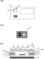
- figure 1 shows a schematic representation of a banknote 1 with a transparent window area 3 (shown in broken lines), which is provided with a security element 2 according to the invention in the form of a patch.
- the bank note 1 is based on a paper substrate which has a continuous gap in area 3 .
- the continuous gap is covered on at least one side of the paper substrate by the security element according to the invention, which is present as a laminate film.
- the paper substrate can optionally be provided with an additional transparent film.
- the additional transparent film can, for example, cover at least the area of the continuous recess.
- the banknote shown has the denomination "20" produced by printing in the lower left area.
- the figure 2 shows a security element 2 according to the invention according to a first embodiment in plan view.
- the security element 2 is semi-transparent in the shaded area, the viewer perceives this area when viewed in incident light in the form of a gold-colored metallization, when viewed in transmitted light the viewer perceives this area in a blue hue.
- the security element 2 is opaque, metallic, both when viewed in reflected light and when viewed in transmitted light.
- the security element 2 is transparent in the white area (see the number "0").
- the semi-transparent areas are in the figure 3 with the letter "A” and form the in the figure 2 shaded background surrounding the number "20".
- the central area of the embossing varnish 6 is provided with an opaque, reflective Al layer.
- the opaque, metallic area is in the figure 3 with provided with the letter “C” and forms the in the figure 2 shown digit "2".
- the transparent areas are in the figure 3 denoted by the letter "B” and form the in the figure 2 shown digit "0".
- the security element shown in the form of a laminate film is applied to the paper substrate of banknote 1 by means of an adhesive layer 11, in particular a heat-seal lacquer layer, so that recess 3 in the banknote is closed on one side by the security element and the viewer in the window area of the banknote can see the optical reflected light and can perceive transmitted light effects particularly well.
- the adhesive layer 11 can optionally be arranged over an optional primer layer 10 .
- the security element shows, for example, interesting three-dimensional warping effects in the areas “A” and/or “B”.
- the figure 5 shows a detail of a security element according to the invention according to a third embodiment, which is based on the first embodiment according to FIG figure 3 is ajar, in cross-sectional view.
- the micro- or nanostructure of the embossing lacquer layer 5 and the semi-transparent thin-film elements (with the layers 6, 7 and 8) that adapt to the relief of the embossing lacquer layer 5 on the one hand and the opaque, metallic Al layer 9 on the other hand are highlighted in the drawing.
- the figure 4 shows a detail of a security element according to the invention according to a second embodiment in a cross-sectional view. That in the figure 4 security element shown is located also like those in the Figures 3 and 5 shown security elements in the form of a laminate film and is suitable for covering the recess 3 in the figure 1 shown banknote 1.
- the security element shown contains a carrier 4 in the form of a transparent plastic film, for example a PET film. Above the carrier 4 there is an embossing lacquer 5 which is provided with a relief structure in the form of a microstructure or nanostructure.
- the embossing varnish 5 there are semi-transparent thin-film elements on the left side, on the right-hand side and in the central area, which give a viewer a different color impression when viewed in incident light and when viewed in transmitted light.
- Such a thin-film element appears gold in reflected light and blue in transmitted light.
- Certain areas of the left and right semi-transparent thin-film elements additionally have a reflective Al layer 12 and in this way form opaque, metallic areas.
- the semi-transparent thin-film elements (each containing the layers 6, 7 and 8) and the opaque, metallic layer 12 are covered by the protective lacquer 10.
- an ink acceptance layer or print acceptance layer (not shown in the figure) can be arranged above the protective lacquer 10 so that the security element can also be printed with ink.
- the security element shown in the form of a laminate film is applied to the paper substrate of the banknote 1 by means of an adhesive layer 11, in particular a heat-seal lacquer layer, so that the recess 3 of the banknote is one-sided from the security element is closed and the viewer in the window area of the banknote can perceive the optical incident and transmitted light effects particularly well.
- the security element shown appears metallic and opaque (eg silver) to the observer in the areas "C” and gold-colored in the semi-transparent areas "A” when viewed in reflected light and in a blue hue when viewed in transmitted light.
- the "B" areas represent the transparent areas.
- the figure 6 shows a security element not according to the invention according to a fourth example (comparative example) in plan view.
- the fourth example is in connection with the Figures 1 to 4 described embodiment based.
- security element shown takes the viewer in the case of figure 6 the numeral "2" is golden when viewed in reflected light and true in blue when viewed in transmitted light, ie, the numeral "2" is formed in the shape of a semitransparent region, eg, by means of a semitransparent Al/SiO 2 /Al thin film element.
- the digit "0" is formed in the shape of a transparent area.
- the background surrounding the digits "2" and “0” is in the form of an opaque, metallic surface, in the example in the form of a reflective Al layer.
- the figure 7 shows a schematic representation of a bank note 13 with a security element 14 according to the invention in the form of a security thread or security strip.
- Banknote 13 is a plastic banknote and is based on a polymer substrate.
- the security element 14 was formed in the form of a transfer foil (ie with a detachable carrier substrate) before being applied to the polymer substrate of the bank note 13 .
- the figure 8 shows the section of a security element 14 according to the invention according to a fifth exemplary embodiment in plan view.
- the security element 14 is semi-transparent in the shaded area, the viewer perceives this area when viewed in incident light in the form of a gold-colored metallization, when viewed in transmitted light the viewer perceives this area in a blue hue.
- the security element 14 In the black area (see the black numbers "20" on the left and right), the security element 14 is opaque, metallic, both when viewed in reflected light and when viewed in transmitted light.
- the white area see the middle white number "20"
- the security element 2 is transparent.
- the semi-transparent areas are in the figure 9 with the letter "A” and form the in the figure 8 shaded background surrounding the numbers "20".
- the central area of the embossing varnish 6 is provided with an opaque, reflective Al layer.
- the opaque, metallic area is in the figure 9 provided with the letter “C” and forms the in the figure 8 black numbers "20" shown left and right.
- the transparent areas are in the figure 9 denoted by the letter "B” and form the in the figure 8 shown middle white number "20".
- the security element shown in the form of a transfer film is applied to the polymer substrate of the banknote 13 by means of an adhesive layer 11, in particular a heat-sealing lacquer layer. After application to the polymer substrate, the temporary carrier 4 is detached from the security element applied to the bank note. In this way, the layer thickness of the bank note 14 in the area of the security element 14 is not too high.
- the figure 10 shows a security element not according to the invention according to a sixth example (comparative example) in plan view.
- the sixth example is in connection with the Figures 7 to 9 described embodiment based.
- security element shown takes the viewer in the case of figure 10 the left and
- the shaded numbers "20" shown on the right are gold-colored when viewed in incident light and blue when viewed in transmitted light, ie the shaded numbers "20" are each formed in the shape of a semi-transparent area, e.g. by means of a semi-transparent Al/SiO 2 /Al thin film element.
- the middle white number "20" is formed in the shape of a transparent area.
- the background surrounding the numbers "20” is in the form of an opaque, metallic surface, in the example in the form of a reflective Al layer.
- FIG. 11 describe a seventh example (comparative example) that is related to the Figures 7 to 9 is based on the exemplary embodiment described, in which the viewer sees the numbers "20" shown on the left and right, but not when viewing in reflected light (see figure 11 ), but only when viewed in transmitted light (see the figure 12 ) can recognize.
- the seventh example is also in the figure 9
- the layer structure shown is used, with the central region of the embossing lacquer 5 not being provided with an opaque, reflective, silver Al layer, but with an opaque, reflective, gold-colored layer (eg an Au layer or a Cu layer).
- This opaque, metallic, gold-colored area forms in the Figures 11 and 12 the black background.
- the numbers "20" shown on the left and right are each based on a semi-transparent thin film which is gold-colored when viewed in incident light and bluish when viewed in transmitted light. Therefore, the viewer can see the two numbers shown on the left and right "20" when viewed in reflected light (see the figure 11 ) not perceive, but only when viewed in transmitted light (see the figure 12 ).
- the in the Figures 11 and 12 The middle number "20" shown is in the form of a transparent area (see the area "B" in Fig figure 9 ) educated.
- a silver Al layer can be used and for the semi-transparent thin layer (see layers 6, 7 and 8 in the figure 9 ) an Al/SiO 2 /Al layer structure or an Al/SiO 2 /Al layer structure which is silver when viewed in reflected light and violet when viewed in transmitted light.
Description
Die Erfindung betrifft ein Sicherheitselement zur Absicherung von Wertdokumenten mit einem Träger, einem auf dem Träger über eine Prägelackschicht angeordneten Schichtaufbau und einer für das Verkleben des Sicherheitselements mit einem Wertgegenstand geeigneten Klebschicht, wobei der Schichtaufbau opake, metallische Bereiche, semitransparente Bereiche, die einem Betrachter bei der Betrachtung im Auflicht und bei der Betrachtung im Durchlicht einen unterschiedlichen Farbeindruck vermitteln, und transparente Bereiche aufweist. Die Erfindung betrifft des Weiteren Verfahren zum Herstellen eines derartigen Sicherheitselements und einen Datenträger mit einem solchen Sicherheitselement.The invention relates to a security element for protecting documents of value with a carrier, a layer structure arranged on the carrier via an embossing lacquer layer and an adhesive layer suitable for bonding the security element to an object of value, the layer structure comprising opaque, metallic areas, semi-transparent areas that an observer convey a different color impression when viewed in reflected light and when viewed in transmitted light, and has transparent areas. The invention also relates to a method for producing such a security element and a data carrier with such a security element.
Datenträger, wie etwa Wert- oder Ausweisdokumente, oder andere Wertgegenstände, wie etwa Markenartikel, werden zur Absicherung oft mit Sicherheitselementen versehen, die eine Überprüfung der Echtheit der Datenträger gestatten und die zugleich als Schutz vor unerlaubter Reproduktion dienen. Eine besondere Rolle bei der Echtheitsabsicherung spielen Sicherheitselemente mit betrachtungswinkelabhängigen Effekten, da diese selbst mit modernsten Kopiergeräten nicht reproduziert werden können. Die Sicherheitselemente werden dabei mit optisch variablen Elementen ausgestattet, die dem Betrachter unter unterschiedlichen Betrachtungswinkeln einen unterschiedlichen Bildeindruck vermitteln und beispielsweise je nach Betrachtungswinkel einen anderen Farb- oder Helligkeitseindruck und/ oder ein anderes graphisches Motiv zeigen.Data carriers, such as value or identification documents, or other valuables, such as branded items, are often provided with security elements for protection, which allow the authenticity of the data carrier to be checked and which at the same time serve as protection against unauthorized reproduction. Security elements with effects that depend on the viewing angle play a special role in securing authenticity, as these cannot be reproduced even with the most modern copiers. The security elements are equipped with optically variable elements that give the viewer a different image impression from different viewing angles and, for example, show a different color or brightness impression and/or a different graphic motif depending on the viewing angle.
In diesem Zusammenhang ist bekannt, Sicherheitselemente mit mehrschichtigen Dünnschichtelementen einzusetzen, deren Farbeindruck sich für den Betrachter mit dem Betrachtungswinkel ändert (im Folgenden als Farbkippeffekt bezeichnet). Der Farbkippeffekt beruht bei solchen Dünnschichtelementen auf betrachtungswinkelabhängigen Interferenzeffekten durch Mehrfachreflexionen in den verschiedenen Teilschichten des Elements. Der Wegunterschied des an den verschiedenen Schichten reflektierten Lichts hängt einerseits von der optischen Dicke einer dielektrischen Abstandsschicht ab, die den Abstand zwischen einer semitransparenten Absorberschicht und einer Reflexionsschicht festlegt, und variiert andererseits mit dem jeweiligen Betrachtungswinkel. Da der Wegunterschied in der Größenordnung der Wellenlänge des sichtbaren Lichts liegt, ergibt sich aufgrund von Auslöschung und Verstärkung bestimmter Wellenlängen ein winkelabhängiger Farbeindruck für den Betrachter. Durch eine geeignete Wahl von Material und Dicke der dielektrischen Abstandsschicht können eine Vielzahl unterschiedlicher Farbkippeffekte gestaltet werden.In this connection it is known to use security elements with multi-layer thin-layer elements, the color impression of which changes for the observer with the viewing angle (hereinafter referred to as the color shift effect). In the case of such thin-film elements, the color shift effect is dependent on the viewing angle Interference effects due to multiple reflections in the various sub-layers of the element. The path difference of the light reflected from the different layers depends on the one hand on the optical thickness of a dielectric spacer layer, which defines the distance between a semitransparent absorber layer and a reflection layer, and on the other hand varies with the respective viewing angle. Since the path difference is of the order of magnitude of the wavelength of visible light, an angle-dependent color impression results for the viewer due to the extinction and amplification of certain wavelengths. A large number of different color shift effects can be designed by a suitable choice of material and thickness of the dielectric spacer layer.
Darüber hinaus sind (Durchsichts-)Sicherheitselemente mit mehrschichtigen Dünnschichtelementen bekannt, die bei Betrachtung im Auflicht, d.h. in Reflexion, in einer ersten Farbe erscheinen und bei Betrachtung im Durchlicht, d.h. in Transmission, in einer zweiten Farbe erscheinen. Die
Die
Die
Die
Ausgehend davon liegt der Erfindung die Aufgabe zugrunde, ein Sicherheitselement der eingangs genannten Art mit hoher Fälschungssicherheit und attraktivem visuellen Erscheinungsbild anzugeben.Proceeding from this, the invention is based on the object of specifying a security element of the type mentioned at the outset with a high degree of protection against counterfeiting and an attractive visual appearance.
Diese Aufgabe wird durch die Merkmale der unabhängigen Ansprüche gelöst. Weiterbildungen der Erfindung sind Gegenstand der Unteransprüche.This object is solved by the features of the independent claims. Developments of the invention are the subject matter of the dependent claims.
- 1. (Erster Aspekt der Erfindung) Sicherheitselement zur Absicherung von Wertdokumenten wie in Anspruch 1 definiert.1. (First aspect of the invention) Security element for protecting documents of value as defined in claim 1.
-
2. (Bevorzugte Ausgestaltung) Sicherheitselement wie in Anspruch 2 definiert.2. (Preferred embodiment) Security element as defined in
claim 2. -
3. (Bevorzugte Ausgestaltung) Sicherheitselement wie in den Ansprüchen 3 bis 6 definiert.3. (Preferred embodiment) Security element as defined in
claims 3 to 6. -
4. (Bevorzugte Ausgestaltung) Sicherheitselement wie in den Ansprüchen 7 bis 10 definiert.4. (Preferred embodiment) Security element as defined in
claims 7 to 10. -
5. (Bevorzugte Ausgestaltung) Sicherheitselement wie in den Ansprüchen 11 bis 13 definiert.5. (Preferred embodiment) Security element as defined in
claims 11 to 13. -
6. (Zweiter Aspekt der Erfindung) Datenträger wie in den Ansprüchen 14 bis 16 definiert.6. (Second aspect of the invention) Data carrier as defined in
claims 14 to 16. - 7. (Dritter Aspekt der Erfindung) Verfahren zum Herstellen eines Sicherheitselements wie in Anspruch 17 definiert.7. (Third aspect of the invention) Method for producing a security element as defined in claim 17.
- 8. (Vierter Aspekt der Erfindung) Verfahren zum Herstellen eines Sicherheitselements wie in Anspruch 18 definiert.8. (Fourth aspect of the invention) A method for producing a security element as defined in claim 18.
- 9. (Fünfter Aspekt der Erfindung) Verfahren zum Herstellen eines Sicherheitselements wie in Anspruch 19 definiert.9. (Fifth aspect of the invention) Method of producing a security element as defined in claim 19.
Eine Betrachtung im Auflicht ist im Sinne dieser Erfindung eine Beleuchtung des Datenträgers von einer Seite und eine Betrachtung des Datenträgers von derselben Seite. Eine Betrachtung im Auflicht liegt somit beispielsweise dann vor, wenn die Vorderseite des Datenträgers beleuchtet und auch betrachtet wird.In terms of this invention, observation in incident light is illumination of the data carrier from one side and observation of the data carrier from the same side. Observation in reflected light is therefore present, for example, when the front side of the data carrier is illuminated and also viewed.
Eine Betrachtung im Durchlicht ist im Sinne dieser Erfindung eine Beleuchtung eines Datenträgers von einer Seite und eine Betrachtung des Datenträgers von einer anderen Seite, insbesondere der gegenüberliegenden Seite. Eine Betrachtung im Durchlicht liegt somit beispielsweise dann vor, wenn die Rückseite des Datenträgers beleuchtet und die Vorderseite des Datenträgers betrachtet wird. Das Licht scheint somit durch den Datenträger hindurch.In terms of this invention, viewing in transmitted light is illuminating a data carrier from one side and viewing the data carrier from another side, in particular the opposite side. An observation in transmitted light is therefore present, for example, when the back of the data carrier is illuminated and the front of the data carrier is viewed. The light thus shines through the data carrier.
Das Datenträgersubstrat des Datenträgers, z.B. ein Wertdokumentsubstrat, wie etwa ein Banknotensubstrat, ist insbesondere ein Papiersubstrat oder ein Papier-ähnliches Substrat, ein Polymersubstrat, ein Papier/Folie/Papier-Verbundsubstrat oder ein Folie/Papier/Folie-Verbundsubstrat. Ein mit einem Fensterbereich versehenes Wertdokument oder Sicherheitspapier kann im Falle eines Papier-Substrats, eines Papier/Folie/Papier-Verbundsubstrats oder eines Folie/Papier/Folie-Verbundsubstrats z.B. mittels einer durchgehenden Aussparung innerhalb der Papierschicht(en) erzeugt werden. Alternativ kann die Papierschicht mittels einer geeigneten Flüssigkeit, z.B. mittels wässriger Schwefelsäurelösung, in einem bestimmten Bereich transparent gemacht werden. Im Falle eines auf einem transparenten Polymersubstrat basierenden Wertdokuments kann ein Fensterbereich z.B. mittels deckungsgleicher Aussparungen in den auf der Vorder- und Rückseite des Polymersubstrats aufgebrachten opaken Druckschichten erzeugt werden.The data carrier substrate of the data carrier, eg a value document substrate such as a banknote substrate, is in particular a paper substrate or a paper-like substrate, a polymer substrate, a paper/foil/paper composite substrate or a foil/paper/foil composite substrate. A document of value or security paper provided with a window area can, in the case of a paper substrate, a paper/foil/paper composite substrate or a foil/paper/foil composite substrate, for example by means of a continuous recess within the paper layer(s) be generated. Alternatively, the paper layer can be made transparent in a certain area by means of a suitable liquid, for example by means of an aqueous sulfuric acid solution. In the case of a document of value based on a transparent polymer substrate, a window area can be produced, for example, by means of congruent gaps in the opaque printed layers applied to the front and back of the polymer substrate.
Gemäß der Erfindung ist bei einem gattungsgemäßen Sicherheitselement vorgesehen, einen Träger, d.h. ein Trägersubstrat wie etwa eine Folie, mit einer Prägelackschicht mit eingeprägter Reliefstruktur und einem Schichtaufbau auszustatten, der opake, metallische Bereiche, semitransparente Bereiche, die einem Betrachter bei der Betrachtung im Auflicht und bei der Betrachtung im Durchlicht einen unterschiedlichen Farbeindruck vermitteln, und transparente Bereiche aufweist.According to the invention, in a generic security element, a carrier, i.e. a carrier substrate such as a film, is provided with an embossing lacquer layer with an embossed relief structure and a layer structure that contains opaque, metallic areas, semi-transparent areas that are visible to a viewer when viewed in reflected light and give a different color impression when viewed in transmitted light, and has transparent areas.
Die opaken, metallischen Bereiche werden insbesondere mittels einer z.B. durch Aufdampfen erhältlichen Metallisierung bzw. Reflexionsschicht gebildet, vorzugsweise durch eine Aluminiumschicht. Grundsätzlich kommen für die Metallisierung jedoch auch andere Metalle, wie etwa Silber, Nickel, Kupfer, Eisen, Chrom oder Gold in Betracht. Alternativ können die opaken, metallischen Bereiche durch eine drucktechnisch erhältliche Reflexionsschicht gebildet werden. Zur Erzeugung der Reflexionsschicht geeignete plättchenförmige Metallpigmente sind aus der
Der Schichtaufbau des erfindungsgemäßen Sicherheitselements gemäß einer ersten Variante weist opake, metallische Bereiche, semitransparente Bereiche, die einem Betrachter bei der Betrachtung im Auflicht und bei der Betrachtung im Durchlicht einen unterschiedlichen Farbeindruck vermitteln, und transparente Bereiche auf, wobei sowohl die transparenten Bereiche als auch die opaken, metallischen Bereiche jeweils in Form von Mustern, Zeichen oder einer Codierung gebildet sind und die semitransparenten Bereiche einen Hintergrund darstellen. Der Schichtaufbau eines nicht erfindungsgemäßen Sicherheitselements gemäß einer zweiten Variante weist opake, metallische Bereiche, semitransparente Bereiche, die einem Betrachter bei der Betrachtung im Auflicht und bei der Betrachtung im Durchlicht einen unterschiedlichen Farbeindruck vermitteln, und transparente Bereiche auf, wobei sowohl die transparenten Bereiche als auch die semitransparenten Bereiche jeweils in Form von Mustern, Zeichen oder einer Codierung gebildet sind und die opaken, metallischen Bereiche einen Hintergrund darstellen. Beiden Varianten liegt die allgemeine Idee zugrunde, ein Sicherheitselement bereitzustellen, bei dem zwei separate Bereiche jeweils in Form von Mustern, Zeichen oder einer Codierung gebildet sind, wobei ein in Form von Mustern, Zeichen oder einer Codierung gebildeter Bereich je nach Betrachtung im Auflicht oder im Durchlicht einen unterschiedlichen Farbeindruck aufweist. Gemäß einer bevorzugten Ausführungsform ist der eine, in Form von Mustern, Zeichen oder einer Codierung gebildete Bereich bei der Betrachtung im Auflicht zunächst nicht wahrnehmbar, sondern erst bei der Betrachtung im Durchlicht. In diesem Fall ist insbesondere die Farbe der semitransparenten Bereiche bei der Betrachtung im Auflicht mit der Farbe der opaken, metallischen Bereiche identisch. Eine bei der Betrachtung im Auflicht versteckte Information, die erst bei der Betrachtung im Durchlicht erkennbar ist, steigert das Interesse des Betrachters und erhöht die Fälschungssicherheit des jeweiligen Wertgegenstands.The layer structure of the security element according to the invention according to a first variant has opaque, metallic areas, semi-transparent areas that give a viewer a different color impression when viewed in reflected light and when viewed in transmitted light, and transparent areas, with both the transparent areas and the opaque, metallic areas are each formed in the form of patterns, characters or coding and the semi-transparent areas represent a background. The layer structure of a non-inventive security element according to a second variant has opaque, metallic areas, semi-transparent areas that give a viewer a different color impression when viewed in reflected light and when viewed in transmitted light, and transparent areas, with both the transparent areas and the semi-transparent areas are each formed in the form of patterns, characters or a code and the opaque, metallic areas represent a background. Both variants are based on the general idea of providing a security element in which two separate areas are each formed in the form of patterns, characters or a code, with an area formed in the form of patterns, characters or a code depending on Viewing in reflected light or in transmitted light has a different color impression. According to a preferred embodiment, the one area formed in the form of patterns, characters or a code is initially not perceptible when viewed in reflected light, but only when viewed in transmitted light. In this case, in particular, the color of the semi-transparent areas is identical to the color of the opaque, metallic areas when viewed in reflected light. Information hidden when viewed in incident light, which is only recognizable when viewed in transmitted light, increases the viewer's interest and increases the counterfeit security of the respective object of value.
Die semitransparenten Bereiche, die einem Betrachter bei der Betrachtung im Auflicht und bei der Betrachtung im Durchlicht einen unterschiedlichen Farbeindruck vermitteln, basieren insbesondere auf einem mehrschichtigen Aufbau mit zwei semitransparenten metallischen Schichten und einer zwischen den zwei semitransparenten metallischen Schichten angeordneten dielektrischen Schicht. Ein solcher mehrschichtiger Aufbau, der bei der Betrachtung im Auflicht goldfarben erscheint und bei der Betrachtung im Durchlicht einen blauen Farbton zeigt, ist z.B. aus der
Geeignete mehrschichtige Aufbauten mit zwei semitransparenten metallischen Schichten und einer zwischen den zwei semitransparenten metallischen Schichten angeordneten dielektrischen Schicht haben typischerweise die folgende gegenständliche Beschaffenheit:
- die beiden semitransparenten metallischen Schichten werden bevorzugt von Al oder Ag gewählt; die dielektrische Schicht ist insbesondere eine SiO2-Schicht;
- im Falle, dass jede der beiden semitransparenten metallischen Schichten auf Al beruht, liegt die jeweilige bevorzugte Schichtdicke in einem Bereich von 5 nm bis 20 nm, insbesondere bevorzugt in einem Bereich von 10 nm bis 14 nm; die dielektrische SiO2-Schicht hat vorzugsweise eine Schichtdicke in einem Bereich von 50 nm bis 450 nm, weiter bevorzugt in einem Bereich von 80 nm bis 260 nm und insbesondere bevorzugt in einem Bereich von 210 nm bis 260 nm, wobei die Bereiche von 80 nm bis 100 nm und von 210 nm bis 240 nm speziell für die Bereitstellung eines Gold/Blau-Farbwechsels besonders bevorzugt werden;
- im Falle, dass jede der beiden semitransparenten metallischen Schichten auf Ag beruht, liegt die jeweilige bevorzugte Schichtdicke in einem Bereich von 15 nm bis 25 nm; die dielektrische SiO2-Schicht hat vorzugsweise eine Schichtdicke in einem Bereich von 50 nm bis 450 nm, weiter bevorzugt in einem Bereich von 80 nm bis 260 nm und insbesondere bevorzugt in einem Bereich von 210 nm bis 260 nm, wobei die Bereiche von 80 nm bis 100 nm und von 210 nm bis 240 nm speziell für die Bereitstellung eines Gold/Blau-Farbwechsels besonders bevorzugt werden.
- the two semi-transparent metallic layers are preferably chosen from Al or Ag; the dielectric layer is in particular an SiO 2 layer;
- in the event that each of the two semitransparent metallic layers is based on Al, the respective preferred layer thickness is in a range from 5 nm to 20 nm, particularly preferably in a range from 10 nm to 14 nm; the dielectric SiO 2 layer preferably has a layer thickness in a range from 50 nm to 450 nm, more preferably in a range from 80 nm to 260 nm and particularly preferably in a range from 210 nm to 260 nm, the ranges from 80 nm to 100 nm and from 210 nm to 240 nm are especially preferred for providing a gold/blue color change;
- in the event that each of the two semi-transparent metallic layers is based on Ag, the respective preferred layer thickness is in a range from 15 nm to 25 nm; the dielectric SiO 2 layer preferably has a layer thickness in a range from 50 nm to 450 nm, more preferably in a range from 80 nm to 260 nm and particularly preferably in a range from 210 nm to 260 nm, the ranges from 80 nm to 100 nm and from 210 nm to 240 nm are particularly preferred especially for providing a gold/blue color change.
Die oben genannten mehrschichtigen Schichtaufbauten ermöglichen nicht nur die Erzeugung einer semitransparenten Funktionsschicht, die bei Betrachtung im Auflicht goldfarben erscheint und bei der Betrachtung im Durchlicht einen blauen Farbton zeigt, sondern es können je nach Wahl der Schichtdicke insbesondere der dielektrischen Schicht weitere Farbwechsel erzeugt werden, z.B.
- im Auflicht Magenta, im Durchlicht Blau-Grün;
- im Auflicht Türkis, im Durchlicht Orange-Gelb;
- im Auflicht Gold, im Durchlicht Blau-Violett;
- im Auflicht Silber, im Durchlicht Violett.
- magenta in reflected light, blue-green in transmitted light;
- turquoise in incident light, orange-yellow in transmitted light;
- reflected light gold, transmitted light blue-violet;
- reflected light silver, transmitted light violet.
Die semitransparenten Bereiche, die einem Betrachter bei der Betrachtung im Auflicht und bei der Betrachtung im Durchlicht einen unterschiedlichen Farbeindruck vermitteln, können des Weiteren mittels einer Effektpigment-Zusammensetzung erhalten werden. Druckschichten auf Basis einer Effektpigment-Zusammensetzung, die bei der Betrachtung im Auflicht eine andere Farbe wie bei der Betrachtung im Durchlicht zeigen, insbesondere einen Gold/Blau-Farbwechsel, einen Gold/Violett-Farbwechsel, einen Grün-Gold/Magenta-Farbwechsel, einen Violett/Grün-Farbwechsel oder einen Silber/Opak-Farbwechsel, werden z.B. in der
Das erfindungsgemäße Sicherheitselement kann insbesondere als eine sogenannte Laminatfolie ausgestaltet sein, bei der der Träger bzw. das Trägersubstrat mit der Prägelackschicht fest verankert ist. Die Laminatfolie, die insbesondere in Form eines Patch, eines Streifens oder eines Fadens vorliegt, kann dann zusammen mit dem Träger auf ein Wertdokumentsubstrat aufgebracht werden. Insbesondere kann auf diese Weise ein Fenster oder eine Aussparung im Wertdokumentsubstrat verschlossen werden.The security element according to the invention can in particular be designed as a so-called laminate film in which the carrier or the carrier substrate is firmly anchored with the embossing lacquer layer. The laminate film, which is present in particular in the form of a patch, a strip or a thread, can then be applied to a value-document substrate together with the carrier. In particular, a window or a recess in the value-document substrate can be closed in this way.
Das erfindungsgemäße Sicherheitselement kann des Weiteren als eine sogenannte Transferfolie ausgestaltet sein, bei der der Träger bzw. das Trägersubstrat mit der Prägelackschicht nicht fest verankert, sondern von der Prägelackschicht ablösbar ist. Die Transferfolie, die insbesondere in Form eines Patch, eines Streifens oder eines Fadens vorliegt, kann auf ein Wertdokumentsubstrat aufgebracht werden, ohne dass das Trägersubstrat der Transferfolie auf dem Wertdokumentsubstrat zurückbleibt. Ein solches Vorgehen ist insbesondere im Falle, dass das mit dem Sicherheitselement auszustattende Wertdokumentsubstrat ein Polymersubstrat ist, geeignet. Auf diese Weise ist die Schichtdicke im erhaltenen Erzeugnis nicht allzu hoch.Furthermore, the security element according to the invention can be designed as a so-called transfer film in which the carrier or the carrier substrate is not firmly anchored with the embossing lacquer layer but can be detached from the embossing lacquer layer. The transfer film, which is present in particular in the form of a patch, a strip or a thread, can be applied to a value-document substrate without the carrier substrate of the transfer film remaining on the value-document substrate. Such a procedure is particularly suitable in the case that the value document substrate to be equipped with the security element is a polymer substrate. In this way the layer thickness in the product obtained is not too high.
Gemäß einer vorteilhaften Variante weist das erfindungsgemäße Sicherheitselement, insbesondere im Falle des Vorliegens als eine Laminatfolie, in der Reihenfolge die folgenden Schichten auf:
- eine optionale Farbannahmeschicht bzw. Druckannahmeschicht;
- ein Trägersubstrat, z.B. Polyethylenterephthalat(PET)-Folie;
- eine Prägelackschicht, die insbesondere eine diffraktive Struktur bildende Reliefstruktur und/oder eine Mikrospiegelanordnung bildende Reliefstruktur aufweist;
- die Schicht bzw. die Schichten, die die opaken, metallischen Bereiche einerseits und die semitransparenten Bereiche, die einem Betrachter bei der Betrachtung im Auflicht und bei der Betrachtung im Durchlicht einen unterschiedlichen Farbeindruck vermitteln, bilden; dazwischen sind die transparenten Bereiche angeordnet;
- optional eine Primerschicht;
- eine Klebschicht, z.B. eine Heißsiegelbeschichtung, die für das Verkleben des Sicherheitselements mit dem Datenträgersubstrat geeignet ist.
- an optional ink acceptance layer;
- a carrier substrate, eg, polyethylene terephthalate (PET) film;
- an embossing lacquer layer, which has in particular a relief structure forming a diffractive structure and/or a relief structure forming a micromirror arrangement;
- the layer or layers which form the opaque, metallic areas on the one hand and the semi-transparent areas which give a viewer a different color impression when viewed in reflected light and when viewed in transmitted light; the transparent areas are arranged in between;
- optionally a primer layer;
- an adhesive layer, eg a heat-seal coating, which is suitable for gluing the security element to the data carrier substrate.
Gemäß einer weiteren vorteilhaften Variante weist das erfindungsgemäße Sicherheitselement, insbesondere im Falle des Vorliegens als eine Laminatfolie, in der Reihenfolge die folgenden Schichten auf:
- eine Klebschicht, z.B. eine Heißsiegelbeschichtung, die für das Verkleben des Sicherheitselements mit dem Datenträgersubstrat geeignet ist;
- eine optionale Primerschicht;
- ein Trägersubstrat, z.B. Polyethylenterephthalat(PET)-Folie;
- eine Prägelackschicht, die insbesondere eine diffraktive Struktur bildende Reliefstruktur und/oder eine Mikrospiegelanordnung bildende Reliefstruktur aufweist;
- die in die Prägelackschicht eingeprägte Reliefstruktur weist die transparenten Bereiche und die semitransparenten Bereiche in zwei separaten Teilbereichen auf und ein Teil der semitransparenten Bereiche ist zusätzlich mit einer mittels Aufdampfen erhältlichen Metallisierung versehen oder ist mit plättchenförmigen Metallpigmenten bedruckt, um auf diese Weise die metallischen, opaken Bereiche zu bilden;
- eine optionale Schutzschicht;
- eine optionale Farbannahmeschicht bzw. Druckannahmeschicht.
- an adhesive layer, eg a heat seal coating, suitable for adhering the security element to the data carrier substrate;
- an optional primer layer;
- a carrier substrate, eg, polyethylene terephthalate (PET) film;
- an embossing lacquer layer, which has in particular a relief structure forming a diffractive structure and/or a relief structure forming a micromirror arrangement;
- the relief structure embossed in the embossing lacquer layer has the transparent areas and the semi-transparent areas in two separate sub-areas and part of the semi-transparent areas is additionally coated with a metallization that can be obtained by vapor deposition provided or printed with flake-form metal pigments so as to form the metallic, opaque areas;
- an optional protective layer;
- an optional ink trapping layer or print trapping layer.
Das erfindungsgemäße Sicherheitselement gemäß der obigen, weiteren vorteilhaften Variante kann insbesondere so ausgestaltet sein, dass die semitransparenten Bereiche auf einem mehrschichtigen Aufbau basieren, der bei der Betrachtung im Auflicht goldfarben erscheint und bei der Betrachtung im Durchlicht einen blauen Farbton zeigt, wobei ein Teil der semitransparenten Bereiche zusätzlich mit einer z.B. mittels Aufdampfen erhältlichen Metallisierung versehen oder ist mit plättchenförmigen Metallpigmenten bedruckt, um auf diese Weise silberne, metallische, opake Bereiche zu bilden.The security element according to the invention according to the above, further advantageous variant can in particular be designed in such a way that the semi-transparent areas are based on a multi-layer structure which appears gold-colored when viewed in reflected light and shows a blue hue when viewed in transmitted light, with part of the semi-transparent Areas are additionally provided with a metallization, e.g. obtainable by vapor deposition, or is printed with platelet-shaped metal pigments in order to form silver, metallic, opaque areas in this way.
Gemäß einer vorteilhaften Variante weist das erfindungsgemäße Sicherheitselement, insbesondere im Falle des Vorliegens als eine Transferfolie, in der Reihenfolge die folgenden Schichten auf:
- eine optionale Farbannahmeschicht bzw. Druckannahmeschicht;
- ein Trägersubstrat, z.B. Polyethylenterephthalat(PET)-Folie;
- eine Prägelackschicht, die insbesondere eine diffraktive Struktur bildende Reliefstruktur und/oder eine Mikrospiegelanordnung bildende Reliefstruktur aufweist;
- die Schicht bzw. die Schichten, die die opaken, metallischen Bereiche einerseits und die semitransparenten Bereiche, die einem Betrachter bei der Betrachtung im Auflicht und bei der Betrachtung im Durchlicht einen unterschiedlichen Farbeindruck vermitteln, bilden; dazwischen sind die transparenten Bereiche angeordnet;
- eine optionale Primerschicht;
- eine Klebschicht, z.B. eine Heißsiegelbeschichtung, die für das Verkleben des Sicherheitselements mit dem Datenträgersubstrat geeignet ist.
- an optional ink acceptance layer;
- a carrier substrate, eg, polyethylene terephthalate (PET) film;
- an embossing lacquer layer, which has in particular a relief structure forming a diffractive structure and/or a relief structure forming a micromirror arrangement;
- the layer or layers which form the opaque, metallic areas on the one hand and the semi-transparent areas which give a viewer a different color impression when viewed in reflected light and when viewed in transmitted light; the transparent areas are arranged in between;
- an optional primer layer;
- an adhesive layer, eg a heat-seal coating, which is suitable for gluing the security element to the data carrier substrate.
Bei der obigen Variante weist die Prägelackschicht im Falle des Vorliegens einer Transferfolie nur eine schwache Haftung am Trägersubstrat auf, was z.B. durch eine schlechte Haftung des Prägelacks am Trägersubstrat oder durch die Einbringung einer speziellen Trennschicht erreicht werden kann.In the above variant, if a transfer film is present, the embossing lacquer layer has only weak adhesion to the carrier substrate, which can be achieved, for example, by poor adhesion of the embossing lacquer to the carrier substrate or by introducing a special separating layer.
Die Erfindung betrifft des Weiteren ein Verfahren zum Herstellen des erfindungsgemäßen Sicherheitselements zur Absicherung von Wertdokumenten mit einem Träger, einem auf dem Träger über eine Prägelackschicht angeordneten Schichtaufbau und einer für das Verkleben des Sicherheitselements mit einem Wertgegenstand geeigneten Klebschicht, wobei der Schichtaufbau opake, metallische Bereiche, semitransparente Bereiche, die einem Betrachter bei der Betrachtung im Auflicht und bei der Betrachtung im Durchlicht einen unterschiedlichen Farbeindruck vermitteln, und transparente Bereiche aufweist, wobei das Verfahren die folgenden Schritte umfasst:
- den Schritt des Bereitstellens eines Trägersubstrats mit einer darauf aufgebrachten Prägelackschicht;
- den Schritt des Aufdruckens einer löslichen Waschfarbe in den Bereichen außerhalb der zu erzeugenden metallischen, opaken Bereiche;
- den Schritt des Aufbringens einer Metallisierung, z.B. eine reflektierende Al-, Cr-, Cu- oder Au-Schicht, insbesondere mittels Aufdampfen, wobei eine Al-Schicht bevorzugt wird;
- den Schritt des Abwaschens der löslichen Waschfarbe zusammen mit der oberhalb der Waschfarbe befindlichen Metallisierung mittels eines Lösungsmittels, sodass metallische, opake Bereiche auf der Prägelackschicht zurückbleiben;
- den Schritt des Aufdruckens einer löslichen Waschfarbe in den Bereichen außerhalb der zu erzeugenden semitransparenten Bereiche;
- den Schritt des Erzeugens eines mehrschichtigen Aufbaus mit zwei semitransparenten metallischen Schichten und einer zwischen den zwei semitransparenten metallischen Schichten angeordneten dielektrischen Schicht, insbesondere mittels Aufdampfen;
- den Schritt des Abwaschens der löslichen Waschfarbe zusammen mit der oberhalb der Waschfarbe befindlichen mehrschichtigen Aufbaus, sodass außer den metallischen, opaken Bereichen auch semitransparente Bereiche auf der Prägelackschicht zurückbleiben und zwischen den metallischen, opaken Bereichen und den semitransparenten Bereichen transparente Bereiche gebildet sind;
- optional den Schritt des Aufbringens einer optionalen Primerschicht; und
- optional den Schritt des Aufbringens einer Klebschicht, z.B. eine Heißsiegellackschicht.
- the step of providing a carrier substrate with an embossing lacquer layer applied thereto;
- the step of printing a soluble wash ink in the areas outside of the metallic opaque areas to be created;
- the step of applying a metallization, eg a reflective Al, Cr, Cu or Au layer, in particular by means of vapor deposition, with an Al layer being preferred;
- the step of washing off the soluble wash ink together with the metallization located above the wash ink using a solvent so that metallic, opaque areas remain on the embossing lacquer layer;
- the step of printing a soluble wash ink in the areas outside of the semi-transparent areas to be created;
- the step of producing a multilayer structure with two semitransparent metallic layers and a dielectric layer arranged between the two semitransparent metallic layers, in particular by means of vapor deposition;
- the step of washing off the soluble washing ink together with the multilayer structure located above the washing ink, so that in addition to the metallic, opaque areas, semitransparent areas also remain on the embossing lacquer layer and transparent areas are formed between the metallic, opaque areas and the semitransparent areas;
- optionally the step of applying an optional primer layer; and
- optionally the step of applying an adhesive layer, eg a heat-seal lacquer layer.
Ein weiteres Verfahren zum Herstellen des erfindungsgemäßen Sicherheitselements zur Absicherung von Wertdokumenten mit einem Träger, einem auf dem Träger über eine Prägelackschicht angeordneten Schichtaufbau und einer für das Verkleben des Sicherheitselements mit einem Wertgegenstand geeigneten Klebschicht, wobei der Schichtaufbau opake, metallische Bereiche, semitransparente Bereiche, die einem Betrachter bei der Betrachtung im Auflicht und bei der Betrachtung im Durchlicht einen unterschiedlichen Farbeindruck vermitteln, und transparente Bereiche aufweist, umfasst die folgenden Schritte:
- den Schritt des Bereitstellens eines Trägersubstrats mit einer darauf aufgebrachten Prägelackschicht;
- den Schritt des drucktechnischen Erzeugens metallischer, opaker Bereiche auf der Prägelackschicht mittels einer auf plättchenförmigen Metallpigmenten beruhenden Druckfarbe;
- den Schritt des Aufdruckens einer löslichen Waschfarbe in den Bereichen außerhalb der zu erzeugenden semitransparenten Bereiche;
- den Schritt des Erzeugens eines mehrschichtigen Aufbaus mit zwei semitransparenten metallischen Schichten und einer zwischen den zwei semitransparenten metallischen Schichten angeordneten dielektrischen Schicht, insbesondere mittels Aufdampfen;
- den Schritt des Abwaschens der löslichen Waschfarbe zusammen mit der oberhalb der Waschfarbe befindlichen mehrschichtigen Aufbaus, sodass außer den metallischen, opaken Bereichen auch semitransparente Bereiche auf der Prägelackschicht zurückbleiben und zwischen den metallischen, opaken Bereichen und den semitransparenten Bereichen transparente Bereiche gebildet sind;
- optional den Schritt des Aufbringens einer optionalen Primerschicht; und
- optional den Schritt des Aufbringens einer Klebschicht, z.B. eine Heißsiegellackschicht.
- the step of providing a carrier substrate with an embossing lacquer layer applied thereto;
- the step of producing metallic, opaque areas on the embossing lacquer layer by printing by means of a printing ink based on platelet-shaped metal pigments;
- the step of printing a soluble wash ink in the areas outside of the semi-transparent areas to be created;
- the step of producing a multilayer structure with two semitransparent metallic layers and a dielectric layer arranged between the two semitransparent metallic layers, in particular by means of vapor deposition;
- the step of washing off the soluble washing ink together with the multilayer structure located above the washing ink, so that in addition to the metallic, opaque areas, semitransparent areas also remain on the embossing lacquer layer and transparent areas are formed between the metallic, opaque areas and the semitransparent areas;
- optionally the step of applying an optional primer layer; and
- optionally the step of applying an adhesive layer, eg a heat-seal lacquer layer.
Ein weiteres Verfahren zum Herstellen des erfindungsgemäßen Sicherheitselements zur Absicherung von Wertdokumenten mit einem Träger, einem auf dem Träger über eine Prägelackschicht angeordneten Schichtaufbau und einer für das Verkleben des Sicherheitselements mit einem Wertgegenstand geeigneten Klebschicht, wobei der Schichtaufbau opake, metallische Bereiche, semitransparente Bereiche, die einem Betrachter bei der Betrachtung im Auflicht und bei der Betrachtung im Durchlicht einen unterschiedlichen Farbeindruck vermitteln, und transparente Bereiche aufweist, umfasst die folgenden Schritte:
- den Schritt des Bereitstellens eines Trägersubstrats mit einer darauf aufgebrachten Prägelackschicht;
- den Schritt des Aufdruckens einer löslichen Waschfarbe in den Bereichen außerhalb zu erzeugender semitransparenter Bereiche;
- den Schritt des Erzeugens eines mehrschichtigen Aufbaus mit zwei semitransparenten metallischen Schichten und einer zwischen den zwei semitransparenten metallischen Schichten angeordneten dielektrischen Schicht, insbesondere mittels Aufdampfen;
- den Schritt des Abwaschens der löslichen Waschfarbe zusammen mit der oberhalb der Waschfarbe befindlichen mehrschichtigen Aufbaus, sodass semitransparente Bereiche auf der Prägelackschicht zurückbleiben;
- den Schritt des Aufdruckens einer löslichen Waschfarbe in den Bereichen außerhalb zu erzeugenden metallischen, opaken Bereiche;
- den Schritt des Aufbringens einer Metallisierung, z.B. eine reflektierende Al-, Cr-, Cu- oder Au-Schicht, mittels Aufdampfen, wobei eine Al-Schicht bevorzugt wird, wobei der Schritt so erfolgt, dass ein Teil der semitransparenten Bereiche zusätzlich mit einer mittels Aufdampfen erhältlichen Metallisierung versehen ist, um auf diese Weise die metallischen, opaken Bereiche zu bilden;
- den Schritt des Abwaschens der löslichen Waschfarbe zusammen mit der oberhalb der Waschfarbe befindlichen Metallisierung;
- optional den Schritt des Aufbringens einer optionalen Primerschicht; und
- optional den Schritt des Aufbringens einer Klebschicht, z.B. eine Heißsiegellackschicht.
- the step of providing a carrier substrate with an embossing lacquer layer applied thereto;
- the step of printing a soluble wash ink in the areas outside semitransparent areas to be formed;
- the step of producing a multilayer structure with two semitransparent metallic layers and a dielectric layer arranged between the two semitransparent metallic layers, in particular by means of vapor deposition;
- the step of washing off the soluble wash ink together with the multi-layer structure located above the wash ink so that semi-transparent areas remain on the embossing varnish layer;
- the step of printing a soluble wash ink in the areas outside of metallic opaque areas to be created;
- the step of applying a metallization, eg a reflective Al, Cr, Cu or Au layer, by means of vapor deposition, an Al layer being preferred, the step being carried out in such a way that part of the semi-transparent areas are additionally covered with a means metallization obtainable by vapor deposition so as to form the metallic opaque areas;
- the step of washing off the soluble wash ink along with the metallization located above the wash ink;
- optionally the step of applying an optional primer layer; and
- optionally the step of applying an adhesive layer, eg a heat-seal lacquer layer.
Das erfindungsgemäße Sicherheitselement kann zusätzlich mit magnetischen und/oder fluoreszierenden Sicherheitsmerkmalen ausgestattet werden.The security element according to the invention can additionally be equipped with magnetic and/or fluorescent security features.
Die Erfindung betrifft weiter einen Datenträger mit einem Sicherheitselement der oben beschriebenen Art. Bei dem Datenträger kann es sich um ein Wertdokument, wie eine Banknote, insbesondere eine Papierbanknote, eine Polymerbanknote oder eine Folienverbundbanknote, um eine Aktie, eine Anleihe, eine Urkunde, einen Gutschein, einen Scheck, eine hochwertige Eintrittskarte, aber auch um eine Ausweiskarte, wie etwa eine Kreditkarte, eine Bankkarte, eine Barzahlungskarte, eine Berechtigungskarte, einen Personalausweis oder eine Passpersonalisierungsseite handeln.The invention further relates to a data carrier with a security element of the type described above. The data carrier can be a document of value, such as a banknote, in particular a paper banknote, a polymer banknote or a foil composite banknote, a share, a bond, a certificate, a voucher , a check, a premium ticket, but also an identification card, such as a credit card, a bank card, a cash card, an authorization card, an ID card or a passport personalization page.
Weitere Ausführungsbeispiele sowie Vorteile der Erfindung werden nachfolgend anhand der Figuren erläutert, bei deren Darstellung auf eine maßstabs- und proportionsgetreue Wiedergabe verzichtet wurde, um die Anschaulichkeit zu erhöhen.Further exemplary embodiments and advantages of the invention are explained below with reference to the figures, which are not shown to scale and proportions in order to improve clarity.
Es zeigen:
- Figur 1
- eine schematische Darstellung einer Banknote mit einem erfindungsgemäßen Sicherheitselement;
Figur 2- ein erfindungsgemäßes Sicherheitselement gemäß einem ersten Ausführungsbeispiel in Draufsicht;
Figur 3- einen Ausschnitt des erfindungsgemäßen Sicherheitselements gemäß dem ersten Ausführungsbeispiel in Querschnittansicht;
Figur 4- einen Ausschnitt eines erfindungsgemäßen Sicherheitselements gemäß einem zweiten Ausführungsbeispiel in Querschnittansicht;
Figur 5- einen Ausschnitt eines erfindungsgemäßen Sicherheitselements gemäß einem dritten Ausführungsbeispiel in Querschnittansicht;
Figur 6- ein nicht erfindungsgemäßes Sicherheitselement gemäß einem vierten Beispiel (Vergleichsbeispiel) in Draufsicht;
Figur 7- eine schematische Darstellung einer Banknote mit einem erfindungsgemäßen Sicherheitselement in Form eines Sicherheitsfadens;
Figur 8- ein erfindungsgemäßes Sicherheitselement gemäß einem fünften Ausführungsbeispiel in Draufsicht;
Figur 9- einen Ausschnitt des erfindungsgemäßen Sicherheitselements gemäß dem fünften Ausführungsbeispiel in Querschnittansicht;
Figur 10- ein nicht erfindungsgemäßes Sicherheitselement gemäß einem sechsten Beispiel (Vergleichsbeispiel) in Draufsicht;
Figur 11- ein nicht erfindungsgemäßes Sicherheitselement gemäß einem siebten Beispiel (Vergleichsbeispiel) bei der Betrachtung im Auflicht; und
Figur 12- das nicht erfindungsgemäße Sicherheitselement gemäß dem siebten Beispiel (Vergleichsbeispiel) bei der Betrachtung im Auflicht.
- figure 1
- a schematic representation of a bank note with a security element according to the invention;
- figure 2
- a security element according to the invention according to a first embodiment in plan view;
- figure 3
- a detail of the security element according to the invention according to the first embodiment in cross-sectional view;
- figure 4
- a detail of a security element according to the invention according to a second embodiment in cross-sectional view;
- figure 5
- a detail of a security element according to the invention according to a third embodiment in cross-sectional view;
- figure 6
- a security element not according to the invention according to a fourth example (comparative example) in plan view;
- figure 7
- a schematic representation of a bank note with a security element according to the invention in the form of a security thread;
- figure 8
- a security element according to the invention according to a fifth embodiment in plan view;
- figure 9
- a detail of the security element according to the invention according to the fifth embodiment in cross-sectional view;
- figure 10
- a security element not according to the invention according to a sixth example (comparative example) in plan view;
- figure 11
- a security element not according to the invention according to a seventh example (comparative example) when viewed in incident light; and
- figure 12
- the security element not according to the invention according to the seventh example (comparative example) when viewed in reflected light.
Die Erfindung wird nun am Beispiel von Sicherheitselementen für Banknoten erläutert.
Die
Die
- 5 bis 15 nm Al / 85 bis 250 nm SiO2 / 5 bis 15 nm Al, insbesondere
- 5 bis 15 nm Al / 85 bis 125 nm SiO2 / 5 bis 15 nm Al; oder
- 15 bis 25 nm Ag / 80 bis 105 nm SiO2 / 15 bis 25 nm Ag;
- 5 to 15 nm Al / 85 to 250 nm SiO 2 / 5 to 15 nm Al, in particular
- 5 to 15 nm Al / 85 to 125 nm SiO 2 / 5 to 15 nm Al; or
- 15 to 25 nm Ag / 80 to 105 nm SiO 2 / 15 to 25 nm Ag;
Die semitransparenten Bereiche sind in der
Der mittlere Bereich der Prägelacks 6 ist mit einer opaken, reflektierenden Al-Schicht versehen. Der opake, metallische Bereich ist in der
Die transparenten Bereiche werden in der
Das in der
Ja nach Ausgestaltung der Mikrostruktur der Prägelackschicht 5 zeigt das Sicherheitselement in den Bereichen "A" und/oder "B" z.B. interessante dreidimensionale Wölbeffekte. Die
Die
Das in der
Das in der
Die
Die
Die
Die
- 5 bis 15 nm Al / 85 bis 250 nm SiO2 / 5 bis 15 nm Al, insbesondere
- 5 bis 15 nm Al / 85 bis 125 nm SiO2 / 5 bis 15 nm Al; oder
- 15 bis 25 nm Ag / 80 bis 105 nm SiO2 / 15 bis 25 nm Ag;
- 5 to 15 nm Al / 85 to 250 nm SiO 2 / 5 to 15 nm Al, in particular
- 5 to 15 nm Al / 85 to 125 nm SiO 2 / 5 to 15 nm Al; or
- 15 to 25 nm Ag / 80 to 105 nm SiO 2 / 15 to 25 nm Ag;
Die semitransparenten Bereiche sind in der
Der mittlere Bereich der Prägelacks 6 ist mit einer opaken, reflektierenden Al-Schicht versehen. Der opake, metallische Bereich ist in der
Die transparenten Bereiche werden in der
Das in der
Die
Im Falle der in den
Im Falle des siebten Beispiels (Vergleichsbeispiel) wird ebenfalls der in der
Die in den
In einer alternativen Variante zu dem oben beschriebenen siebten Beispiel (Vergleichsbeispiel) kann für die opake, metallische, reflektierende Schicht (siehe die Bezugsnummer 9 in der
Die in der
Claims (19)
- Security element (2, 14) for securing value documents (1, 13) having a carrier (4), a layer construction arranged on the carrier (4) via an embossing lacquer layer (5) and an adhesive layer (11) suitable for bonding the security element (2, 14) to a value article (1, 13), wherein the layer construction comprises opaque metallic regions, semitransparent regions, which give an observer a different color impression when observed in incident light and when observed in transmitted light, and transparent regions, wherein both the transparent regions and the opaque metallic regions are each in the form of patterns, signs or a code and the semitransparent regions constitute a background, wherein the embossing lacquer layer (5) is provided with an embossed relief structure, characterized in that
the embossing lacquer layer (5) having an embossed relief structure in the regions each in the form of patterns, signs or a code has the same relief structure and in the regions constituting a background has a further relief structure. - Security element according to Claim 1, wherein the opaque metallic regions are based on a metallization obtainable by vapor deposition or are obtainable by printing and are based on metal pigment flakes.
- Security element according to either of Claims 1 or 2, wherein the semitransparent regions which give an observer a different color impression when observed in incident light and when observed in transmitted light are based on a thin film element comprising two semitransparent mirror layers and a dielectric spacer layer arranged between the two mirror layers.
- Security element according to either of Claims 1 or 2, wherein the semitransparent regions which give an observer a different color impression when observed in incident light and when observed in transmitted light are obtainable by printing using an effect pigment composition.
- Security element according to any of Claims 1 to 4, wherein the relief structure forms a diffractive structure, such as for instance a hologram, a holographic grating image or a hologram-like diffraction structure, or an achromatic structure, for instance a matt structure, or a micromirror arrangement or a blazed grating having a sawtooth groove profile or a fresnel lens arrangement or a combination of two or more of the aforementioned elements.
- Security element according to any of Claims 1 to 5, wherein the embossing lacquer layer having an embossed relief structure in the regions that are each in the form of patterns, signs or a code has the same relief structure and in the regions constituting a background has a further relief structure, namely such that one relief structure forms a diffractive structure and the second relief structure forms a micromirror arrangement.
- Security element according to any of Claims 1 to 6, wherein the regions that are each in the form of patterns, lines or a code are arranged at least partially in register with one another.
- Security element according to any of Claims 1 to 7, wherein (i) the color impression of the semitransparent regions when observed in incident light is identical to the color impression of the opaque metallic regions and the color impression of the semitransparent regions when observed in transmitted light is different from the color impression of the opaque metallic regions or (ii) both the color impression of the semitransparent regions when observed in incident light and the color impression of the semitransparent regions when observed in transmitted light is different from the color impression of the opaque metallic regions.
- Security element according to any of Claims 1 to 8, wherein the relief structure embossed in the embossing lacquer layer comprises the transparent regions, the metallic opaque regions and the semitransparent regions in three separate subregions.
- Security element according to any of Claims 1 to 8, wherein the relief structure embossed in the embossing lacquer layer comprises the transparent regions and the semitransparent regions in two separate subregions and a portion of the semitransparent region is additionally provided with a metallization obtainable by vapor disposition or is printed with metal pigment flakes in order thus to form the metallic opaque regions.
- Security element according to any of Claims 1 to 10, wherein the layer sequence of the security element is as follows:a) carrier;b) embossing lacquer layer with embossed relief structure;c) layer construction comprising opaque metallic regions, semitransparent regions, which give an observer a different color impression when observed in incident light and when observed in transmitted light, and transparent regions;d) adhesive layer suitable for bonding the security element to a value article.
- Security element according to any of Claims 1 to 10, wherein the layer sequence of the security element is as follows:a) adhesive layer suitable for bonding the security element to a value article;b) carrier;c) embossing lacquer layer with embossed relief structure;d) layer construction comprising opaque metallic regions, semitransparent regions, which give an observer a different color impression when observed in incident light and when observed in transmitted light, and transparent regions;e) protective layer, in particular a protective layer based on a protective lacquer.
- Security element according to any of Claims 1 to 12, wherein the security element is a security band, a security strip, a patch or a label for application to a security paper, value document or the like.
- Data carrier (1, 13) having a security element (2, 14) according to any of Claims 1 to 13.
- Data carrier according to Claim 14, wherein the security element is arranged in a transparent window region of the data carrier.
- Data carrier according to Claim 14 or 15, wherein the data carrier is a value document, for instance a banknote, in particular a paper banknote, polymer banknote or film laminate banknote, or identity card.
- Process for producing a security element (2, 14) for securing value documents (1, 13), namely a security element (2, 14) according to any of Claims 1 to 13, having a carrier (4), a layer construction arranged on the carrier (4) via an embossing lacquer layer (5) and an adhesive layer (11) suitable for bonding the security element (2, 14) to a value article (1, 13), wherein the layer construction comprises opaque metallic regions, semitransparent regions which give an observer a different color impression when observed in incident light and when observed in transmitted light, and transparent regions, wherein the process comprises the following steps:- the step of providing a carrier substrate (4) having an embossing lacquer layer (5) applied thereto,- the step of printing a soluble washable ink, in the regions outside the metallic opaque regions to be produced,- the step of applying a metallization, for example a reflecting Al, Cr, Cu or Au layer, in particular by vapor deposition, wherein an Al layer is preferred;- the step of washing off the soluble washable ink together with the metallization disposed above the washable ink using a solvent, so that metallic opaque regions remain on the embossing lacquer layer;- the step of printing a soluble washable ink in the regions outside the semitransparent regions to be produced;- the step of producing a multilayer construction having two semitransparent metallic layers and a dielectric layer arranged between the two semitransparent metallic layers, in particular by vapor deposition;- the step of washing off the soluble washable ink together with the multilayer construction disposed above the washable ink so that in addition to the metallic opaque regions semitransparent regions also remain on the embossing lacquer layer (5) and transparent regions are formed between the metallic opaque regions and the semitransparent regions;- optionally the step of applying an optional primer layer; and- the step of applying an adhesive layer (11), for example a heat-sealing lacquer layer.
- Process for producing a security element (2, 14) for securing value documents (1, 13), namely a security element (2, 14) according to any of Claims 1 to 13, having a carrier (4), a layer construction arranged on the carrier (4) via an embossing lacquer layer (5) and an adhesive layer (11) suitable for bonding the security element (2, 14) to a value article (1, 13), wherein the layer construction comprises opaque metallic regions, semitransparent regions, which give an observer a different color impression when observed in incident light and when observed in transmitted light, and transparent regions, comprising the following steps:- the step of providing a carrier substrate (4) having an embossing lacquer layer (5) applied thereto,- the step of producing by printing a metallic opaque layer on the embossing lacquer layer (5) using a printing ink based on metal pigment flakes;- the step of printing a soluble washable ink in the regions outside the semitransparent regions to be produced;- the step of producing a multilayer construction having two semitransparent metallic layers and a dielectric layer arranged between the two semitransparent metallic layers, in particular by vapor deposition;- the step of washing off the soluble washable ink together with the multilayer construction disposed above the washable ink used in the solvent, so that in addition to the metallic opaque regions semitransparent regions also remain on the embossing lacquer layer (5) and transparent regions are formed between the metallic opaque regions and the semitransparent regions;- optionally the step of applying an optional primer layer; and- the step of applying an adhesive layer (11), for example a heat-sealing lacquer layer.
- Process for producing a security element (2, 14) for securing value documents (1, 13), namely a security element (2, 14) according to any of Claims 1 to 13, having a carrier (4), a layer construction arranged on the carrier (4) via an embossing lacquer layer (5) and an adhesive layer (11) suitable for bonding the security element (2, 14) to a value article (1, 13), wherein the layer construction comprises opaque metallic regions, semitransparent regions, which give an observer a different color impression when observed in incident light and when observed in transmitted light, and transparent regions, comprising the following steps:- the step of providing a carrier substrate (4) having an embossing lacquer layer (5) applied thereto,- the step of printing a soluble washable ink in the regions outside the semitransparent regions to be produced;- the step of producing a multilayer construction having two semitransparent metallic layers and a dielectric layer arranged between the two semitransparent metallic layers, in particular by vapor deposition,- the step of washing off the soluble washable ink together with the multilayer construction disposed above the washable ink, so that semitransparent regions remain on the embossing lacquer layer (5);- the step of printing a soluble washable ink in the regions outside metallic opaque regions to be produced;- the step of applying a metallization, for example a reflecting Al, Cr, Cu or Au layer by vapor deposition, wherein an Al layer is preferred, wherein the step is carried out such that a portion of the semitransparent regions is additionally provided with a metallization obtainable by vapor deposition in order thus to form the metallic opaque regions;- the step of washing off the soluble washable ink together with the metallization disposed above the washable ink;- optionally the step of applying an optional primer layer; and- the step of applying an adhesive layer (11), for example a heat-sealing lacquer layer.
Priority Applications (1)
| Application Number | Priority Date | Filing Date | Title |
|---|---|---|---|
| EP23020047.9A EP4219182A3 (en) | 2018-04-13 | 2019-04-08 | Security element, method for producing same and data carrier equipped with the security element |
Applications Claiming Priority (2)
| Application Number | Priority Date | Filing Date | Title |
|---|---|---|---|
| DE102018003030.0A DE102018003030A1 (en) | 2018-04-13 | 2018-04-13 | Security element, method for producing the same and equipped with the security element disk |
| PCT/EP2019/000112 WO2019197054A1 (en) | 2018-04-13 | 2019-04-08 | Security element, method for producing same, and data carrier equipped with the security element |
Related Child Applications (2)
| Application Number | Title | Priority Date | Filing Date |
|---|---|---|---|
| EP23020047.9A Division EP4219182A3 (en) | 2018-04-13 | 2019-04-08 | Security element, method for producing same and data carrier equipped with the security element |
| EP23020047.9A Division-Into EP4219182A3 (en) | 2018-04-13 | 2019-04-08 | Security element, method for producing same and data carrier equipped with the security element |
Publications (2)
| Publication Number | Publication Date |
|---|---|
| EP3774375A1 EP3774375A1 (en) | 2021-02-17 |
| EP3774375B1 true EP3774375B1 (en) | 2023-06-21 |
Family
ID=66223655
Family Applications (2)
| Application Number | Title | Priority Date | Filing Date |
|---|---|---|---|
| EP19718247.0A Active EP3774375B1 (en) | 2018-04-13 | 2019-04-08 | Security element, method for producing same, and data carrier equipped with the security element |
| EP23020047.9A Pending EP4219182A3 (en) | 2018-04-13 | 2019-04-08 | Security element, method for producing same and data carrier equipped with the security element |
Family Applications After (1)
| Application Number | Title | Priority Date | Filing Date |
|---|---|---|---|
| EP23020047.9A Pending EP4219182A3 (en) | 2018-04-13 | 2019-04-08 | Security element, method for producing same and data carrier equipped with the security element |
Country Status (4)
| Country | Link |
|---|---|
| EP (2) | EP3774375B1 (en) |
| CN (1) | CN111867851B (en) |
| DE (1) | DE102018003030A1 (en) |
| WO (1) | WO2019197054A1 (en) |
Families Citing this family (2)
| Publication number | Priority date | Publication date | Assignee | Title |
|---|---|---|---|---|
| DE102020007728A1 (en) | 2020-12-17 | 2022-06-23 | Giesecke+Devrient Currency Technology Gmbh | Data carrier with composite substrate with a security element arranged in a see-through area |
| DE102022002353A1 (en) * | 2022-06-29 | 2024-01-04 | Giesecke+Devrient Currency Technology Gmbh | Security element, value document and method for producing the same |
Family Cites Families (16)
| Publication number | Priority date | Publication date | Assignee | Title |
|---|---|---|---|---|
| DE10150293B4 (en) * | 2001-10-12 | 2005-05-12 | Ovd Kinegram Ag | security element |
| ATE352430T1 (en) * | 2002-05-14 | 2007-02-15 | Kurz Leonhard Fa | OPTICALLY VARIABLE ELEMENT WITH THIN FILM LAYER SEQUENCE |
| GB0326576D0 (en) | 2003-11-14 | 2003-12-17 | Printetch Ltd | Printing composition |
| DE102008013167A1 (en) * | 2008-03-07 | 2009-09-10 | Giesecke & Devrient Gmbh | Security element and method for its production |
| EP2379650B1 (en) | 2008-12-19 | 2017-11-29 | Basf Se | Thin aluminum flakes |
| DE102009048145A1 (en) * | 2009-10-02 | 2011-04-07 | Giesecke & Devrient Gmbh | Disk with window |
| US9453132B2 (en) | 2009-11-27 | 2016-09-27 | Basf Se | Coating compositions for security elements and holograms |
| DE102009058243A1 (en) | 2009-12-14 | 2011-06-16 | Giesecke & Devrient Gmbh | Thin-film element with multilayer structure |
| WO2013186167A2 (en) | 2012-06-14 | 2013-12-19 | Basf Se | Method for manufacturing security elements and holograms |
| DE102013113283A1 (en) * | 2013-11-29 | 2015-06-03 | Leonhard Kurz Stiftung & Co. Kg | Multilayer body and method for its production |
| RU2641864C2 (en) * | 2013-12-11 | 2018-01-22 | Сикпа Холдинг Са | Optically variable security threads and strips |
| DE102014001842A1 (en) * | 2014-02-11 | 2015-08-13 | Giesecke & Devrient Gmbh | Method for producing a security element with negative writing and security element available therefrom |
| DE102014018204A1 (en) * | 2014-12-09 | 2016-06-09 | Giesecke & Devrient Gmbh | Security element, method for producing the same and equipped with the security element disk |
| DE102014019088A1 (en) * | 2014-12-18 | 2016-06-23 | Giesecke & Devrient Gmbh | Optically variable see-through safety element |
| DE102015010744A1 (en) * | 2015-08-17 | 2017-02-23 | Giesecke & Devrient Gmbh | Security element, method for producing the same and equipped with the security element disk |
| CN105479974B (en) * | 2015-12-01 | 2018-07-13 | 中钞特种防伪科技有限公司 | A kind of optical anti-counterfeit element and the optical anti-counterfeiting product using the optical anti-counterfeit element |
-
2018
- 2018-04-13 DE DE102018003030.0A patent/DE102018003030A1/en not_active Withdrawn
-
2019
- 2019-04-08 WO PCT/EP2019/000112 patent/WO2019197054A1/en active Application Filing
- 2019-04-08 EP EP19718247.0A patent/EP3774375B1/en active Active
- 2019-04-08 CN CN201980019152.7A patent/CN111867851B/en active Active
- 2019-04-08 EP EP23020047.9A patent/EP4219182A3/en active Pending
Also Published As
| Publication number | Publication date |
|---|---|
| CN111867851B (en) | 2022-03-15 |
| EP3774375A1 (en) | 2021-02-17 |
| DE102018003030A1 (en) | 2019-10-17 |
| CN111867851A (en) | 2020-10-30 |
| EP4219182A3 (en) | 2023-11-01 |
| WO2019197054A1 (en) | 2019-10-17 |
| EP4219182A2 (en) | 2023-08-02 |
Similar Documents
| Publication | Publication Date | Title |
|---|---|---|
| EP3337675B1 (en) | Security element, method for producing same, and data carrier equipped with the security element | |
| EP3230081B1 (en) | Security element, method for producing the same and data carrier provided with the security element | |
| EP3374197B1 (en) | Security element, method for producing same, and data carrier equipped with the security element | |
| EP1827864B1 (en) | Safety element provided with an optically-variable layer and method for the production thereof | |
| EP2310211B1 (en) | Security element and method for the production thereof | |
| EP3565722B1 (en) | Value document | |
| EP3260302B1 (en) | Optically variable security element | |
| EP3643511B1 (en) | Security element and data carrier provided with the security element | |
| EP2219168B1 (en) | Transmission security element | |
| DE102008013167A1 (en) | Security element and method for its production | |
| DE102015015733A1 (en) | Security element and the same equipped disk | |
| EP3774375B1 (en) | Security element, method for producing same, and data carrier equipped with the security element | |
| DE102016007064A1 (en) | Security element, value document substrate, with the same provided value document and manufacturing method | |
| EP3212429B1 (en) | Security element having a color-tilting thin-layer element | |
| WO2020088791A1 (en) | Security element and data carrier provided with the security element | |
| WO2017194189A1 (en) | Security element and data carrier | |
| DE102016010616A1 (en) | Security element with several security features | |
| DE102014016028A1 (en) | Security element with color-shifting thin-film element | |
| EP3414100B1 (en) | Data carrier | |
| EP3219508B1 (en) | Security element and data carrier | |
| EP3939801B1 (en) | Valuable document | |
| DE102015015731A1 (en) | Security element and the same equipped disk |
Legal Events
| Date | Code | Title | Description |
|---|---|---|---|
| STAA | Information on the status of an ep patent application or granted ep patent |
Free format text: STATUS: UNKNOWN |
|
| STAA | Information on the status of an ep patent application or granted ep patent |
Free format text: STATUS: THE INTERNATIONAL PUBLICATION HAS BEEN MADE |
|
| PUAI | Public reference made under article 153(3) epc to a published international application that has entered the european phase |
Free format text: ORIGINAL CODE: 0009012 |
|
| STAA | Information on the status of an ep patent application or granted ep patent |
Free format text: STATUS: REQUEST FOR EXAMINATION WAS MADE |
|
| 17P | Request for examination filed |
Effective date: 20201113 |
|
| AK | Designated contracting states |
Kind code of ref document: A1 Designated state(s): AL AT BE BG CH CY CZ DE DK EE ES FI FR GB GR HR HU IE IS IT LI LT LU LV MC MK MT NL NO PL PT RO RS SE SI SK SM TR |
|
| AX | Request for extension of the european patent |
Extension state: BA ME |
|
| DAV | Request for validation of the european patent (deleted) | ||
| DAX | Request for extension of the european patent (deleted) | ||
| GRAP | Despatch of communication of intention to grant a patent |
Free format text: ORIGINAL CODE: EPIDOSNIGR1 |
|
| STAA | Information on the status of an ep patent application or granted ep patent |
Free format text: STATUS: GRANT OF PATENT IS INTENDED |
|
| INTG | Intention to grant announced |
Effective date: 20230110 |
|
| RAP3 | Party data changed (applicant data changed or rights of an application transferred) |
Owner name: GIESECKE+DEVRIENT CURRENCY TECHNOLOGY GMBH |
|
| GRAS | Grant fee paid |
Free format text: ORIGINAL CODE: EPIDOSNIGR3 |
|
| GRAA | (expected) grant |
Free format text: ORIGINAL CODE: 0009210 |
|
| STAA | Information on the status of an ep patent application or granted ep patent |
Free format text: STATUS: THE PATENT HAS BEEN GRANTED |
|
| AK | Designated contracting states |
Kind code of ref document: B1 Designated state(s): AL AT BE BG CH CY CZ DE DK EE ES FI FR GB GR HR HU IE IS IT LI LT LU LV MC MK MT NL NO PL PT RO RS SE SI SK SM TR |
|
| P01 | Opt-out of the competence of the unified patent court (upc) registered |
Effective date: 20230519 |
|
| REG | Reference to a national code |
Ref country code: CH Ref legal event code: EP |
|
| REG | Reference to a national code |
Ref country code: DE Ref legal event code: R096 Ref document number: 502019008263 Country of ref document: DE |
|
| REG | Reference to a national code |
Ref country code: AT Ref legal event code: REF Ref document number: 1580674 Country of ref document: AT Kind code of ref document: T Effective date: 20230715 |
|
| REG | Reference to a national code |
Ref country code: IE Ref legal event code: FG4D Free format text: LANGUAGE OF EP DOCUMENT: GERMAN |
|
| REG | Reference to a national code |
Ref country code: LT Ref legal event code: MG9D |
|
| REG | Reference to a national code |
Ref country code: NL Ref legal event code: MP Effective date: 20230621 |
|
| PG25 | Lapsed in a contracting state [announced via postgrant information from national office to epo] |
Ref country code: SE Free format text: LAPSE BECAUSE OF FAILURE TO SUBMIT A TRANSLATION OF THE DESCRIPTION OR TO PAY THE FEE WITHIN THE PRESCRIBED TIME-LIMIT Effective date: 20230621 Ref country code: NO Free format text: LAPSE BECAUSE OF FAILURE TO SUBMIT A TRANSLATION OF THE DESCRIPTION OR TO PAY THE FEE WITHIN THE PRESCRIBED TIME-LIMIT Effective date: 20230921 |
|
| PG25 | Lapsed in a contracting state [announced via postgrant information from national office to epo] |
Ref country code: RS Free format text: LAPSE BECAUSE OF FAILURE TO SUBMIT A TRANSLATION OF THE DESCRIPTION OR TO PAY THE FEE WITHIN THE PRESCRIBED TIME-LIMIT Effective date: 20230621 Ref country code: NL Free format text: LAPSE BECAUSE OF FAILURE TO SUBMIT A TRANSLATION OF THE DESCRIPTION OR TO PAY THE FEE WITHIN THE PRESCRIBED TIME-LIMIT Effective date: 20230621 Ref country code: LV Free format text: LAPSE BECAUSE OF FAILURE TO SUBMIT A TRANSLATION OF THE DESCRIPTION OR TO PAY THE FEE WITHIN THE PRESCRIBED TIME-LIMIT Effective date: 20230621 Ref country code: LT Free format text: LAPSE BECAUSE OF FAILURE TO SUBMIT A TRANSLATION OF THE DESCRIPTION OR TO PAY THE FEE WITHIN THE PRESCRIBED TIME-LIMIT Effective date: 20230621 Ref country code: HR Free format text: LAPSE BECAUSE OF FAILURE TO SUBMIT A TRANSLATION OF THE DESCRIPTION OR TO PAY THE FEE WITHIN THE PRESCRIBED TIME-LIMIT Effective date: 20230621 Ref country code: GR Free format text: LAPSE BECAUSE OF FAILURE TO SUBMIT A TRANSLATION OF THE DESCRIPTION OR TO PAY THE FEE WITHIN THE PRESCRIBED TIME-LIMIT Effective date: 20230922 |
|
| PG25 | Lapsed in a contracting state [announced via postgrant information from national office to epo] |
Ref country code: FI Free format text: LAPSE BECAUSE OF FAILURE TO SUBMIT A TRANSLATION OF THE DESCRIPTION OR TO PAY THE FEE WITHIN THE PRESCRIBED TIME-LIMIT Effective date: 20230621 |
|
| PG25 | Lapsed in a contracting state [announced via postgrant information from national office to epo] |
Ref country code: SK Free format text: LAPSE BECAUSE OF FAILURE TO SUBMIT A TRANSLATION OF THE DESCRIPTION OR TO PAY THE FEE WITHIN THE PRESCRIBED TIME-LIMIT Effective date: 20230621 |
|
| PG25 | Lapsed in a contracting state [announced via postgrant information from national office to epo] |
Ref country code: ES Free format text: LAPSE BECAUSE OF FAILURE TO SUBMIT A TRANSLATION OF THE DESCRIPTION OR TO PAY THE FEE WITHIN THE PRESCRIBED TIME-LIMIT Effective date: 20230621 |
|
| PG25 | Lapsed in a contracting state [announced via postgrant information from national office to epo] |
Ref country code: IS Free format text: LAPSE BECAUSE OF FAILURE TO SUBMIT A TRANSLATION OF THE DESCRIPTION OR TO PAY THE FEE WITHIN THE PRESCRIBED TIME-LIMIT Effective date: 20231021 |
|
| PG25 | Lapsed in a contracting state [announced via postgrant information from national office to epo] |
Ref country code: SM Free format text: LAPSE BECAUSE OF FAILURE TO SUBMIT A TRANSLATION OF THE DESCRIPTION OR TO PAY THE FEE WITHIN THE PRESCRIBED TIME-LIMIT Effective date: 20230621 Ref country code: SK Free format text: LAPSE BECAUSE OF FAILURE TO SUBMIT A TRANSLATION OF THE DESCRIPTION OR TO PAY THE FEE WITHIN THE PRESCRIBED TIME-LIMIT Effective date: 20230621 Ref country code: RO Free format text: LAPSE BECAUSE OF FAILURE TO SUBMIT A TRANSLATION OF THE DESCRIPTION OR TO PAY THE FEE WITHIN THE PRESCRIBED TIME-LIMIT Effective date: 20230621 Ref country code: PT Free format text: LAPSE BECAUSE OF FAILURE TO SUBMIT A TRANSLATION OF THE DESCRIPTION OR TO PAY THE FEE WITHIN THE PRESCRIBED TIME-LIMIT Effective date: 20231023 Ref country code: IS Free format text: LAPSE BECAUSE OF FAILURE TO SUBMIT A TRANSLATION OF THE DESCRIPTION OR TO PAY THE FEE WITHIN THE PRESCRIBED TIME-LIMIT Effective date: 20231021 Ref country code: ES Free format text: LAPSE BECAUSE OF FAILURE TO SUBMIT A TRANSLATION OF THE DESCRIPTION OR TO PAY THE FEE WITHIN THE PRESCRIBED TIME-LIMIT Effective date: 20230621 Ref country code: EE Free format text: LAPSE BECAUSE OF FAILURE TO SUBMIT A TRANSLATION OF THE DESCRIPTION OR TO PAY THE FEE WITHIN THE PRESCRIBED TIME-LIMIT Effective date: 20230621 Ref country code: CZ Free format text: LAPSE BECAUSE OF FAILURE TO SUBMIT A TRANSLATION OF THE DESCRIPTION OR TO PAY THE FEE WITHIN THE PRESCRIBED TIME-LIMIT Effective date: 20230621 |
|
| PG25 | Lapsed in a contracting state [announced via postgrant information from national office to epo] |
Ref country code: PL Free format text: LAPSE BECAUSE OF FAILURE TO SUBMIT A TRANSLATION OF THE DESCRIPTION OR TO PAY THE FEE WITHIN THE PRESCRIBED TIME-LIMIT Effective date: 20230621 |