EP3774259B1 - Vorrichtung und verfahren zur herstellung von expandierten mikrokugeln - Google Patents
Vorrichtung und verfahren zur herstellung von expandierten mikrokugeln Download PDFInfo
- Publication number
- EP3774259B1 EP3774259B1 EP19713065.1A EP19713065A EP3774259B1 EP 3774259 B1 EP3774259 B1 EP 3774259B1 EP 19713065 A EP19713065 A EP 19713065A EP 3774259 B1 EP3774259 B1 EP 3774259B1
- Authority
- EP
- European Patent Office
- Prior art keywords
- microspheres
- zone
- pressure
- heating zone
- heating
- Prior art date
- Legal status (The legal status is an assumption and is not a legal conclusion. Google has not performed a legal analysis and makes no representation as to the accuracy of the status listed.)
- Active
Links
Images

Classifications
-
- B—PERFORMING OPERATIONS; TRANSPORTING
- B29—WORKING OF PLASTICS; WORKING OF SUBSTANCES IN A PLASTIC STATE IN GENERAL
- B29C—SHAPING OR JOINING OF PLASTICS; SHAPING OF MATERIAL IN A PLASTIC STATE, NOT OTHERWISE PROVIDED FOR; AFTER-TREATMENT OF THE SHAPED PRODUCTS, e.g. REPAIRING
- B29C44/00—Shaping by internal pressure generated in the material, e.g. swelling or foaming ; Producing porous or cellular expanded plastics articles
- B29C44/34—Auxiliary operations
- B29C44/3461—Making or treating expandable particles
-
- B—PERFORMING OPERATIONS; TRANSPORTING
- B01—PHYSICAL OR CHEMICAL PROCESSES OR APPARATUS IN GENERAL
- B01J—CHEMICAL OR PHYSICAL PROCESSES, e.g. CATALYSIS OR COLLOID CHEMISTRY; THEIR RELEVANT APPARATUS
- B01J13/00—Colloid chemistry, e.g. the production of colloidal materials or their solutions, not otherwise provided for; Making microcapsules or microballoons
- B01J13/02—Making microcapsules or microballoons
- B01J13/20—After-treatment of capsule walls, e.g. hardening
-
- C—CHEMISTRY; METALLURGY
- C08—ORGANIC MACROMOLECULAR COMPOUNDS; THEIR PREPARATION OR CHEMICAL WORKING-UP; COMPOSITIONS BASED THEREON
- C08J—WORKING-UP; GENERAL PROCESSES OF COMPOUNDING; AFTER-TREATMENT NOT COVERED BY SUBCLASSES C08B, C08C, C08F, C08G or C08H
- C08J9/00—Working-up of macromolecular substances to porous or cellular articles or materials; After-treatment thereof
- C08J9/16—Making expandable particles
-
- C—CHEMISTRY; METALLURGY
- C08—ORGANIC MACROMOLECULAR COMPOUNDS; THEIR PREPARATION OR CHEMICAL WORKING-UP; COMPOSITIONS BASED THEREON
- C08J—WORKING-UP; GENERAL PROCESSES OF COMPOUNDING; AFTER-TREATMENT NOT COVERED BY SUBCLASSES C08B, C08C, C08F, C08G or C08H
- C08J9/00—Working-up of macromolecular substances to porous or cellular articles or materials; After-treatment thereof
- C08J9/22—After-treatment of expandable particles; Forming foamed products
-
- B—PERFORMING OPERATIONS; TRANSPORTING
- B29—WORKING OF PLASTICS; WORKING OF SUBSTANCES IN A PLASTIC STATE IN GENERAL
- B29K—INDEXING SCHEME ASSOCIATED WITH SUBCLASSES B29B, B29C OR B29D, RELATING TO MOULDING MATERIALS OR TO MATERIALS FOR MOULDS, REINFORCEMENTS, FILLERS OR PREFORMED PARTS, e.g. INSERTS
- B29K2101/00—Use of unspecified macromolecular compounds as moulding material
- B29K2101/12—Thermoplastic materials
-
- B—PERFORMING OPERATIONS; TRANSPORTING
- B29—WORKING OF PLASTICS; WORKING OF SUBSTANCES IN A PLASTIC STATE IN GENERAL
- B29K—INDEXING SCHEME ASSOCIATED WITH SUBCLASSES B29B, B29C OR B29D, RELATING TO MOULDING MATERIALS OR TO MATERIALS FOR MOULDS, REINFORCEMENTS, FILLERS OR PREFORMED PARTS, e.g. INSERTS
- B29K2105/00—Condition, form or state of moulded material or of the material to be shaped
- B29K2105/0076—Microcapsules
-
- B—PERFORMING OPERATIONS; TRANSPORTING
- B29—WORKING OF PLASTICS; WORKING OF SUBSTANCES IN A PLASTIC STATE IN GENERAL
- B29K—INDEXING SCHEME ASSOCIATED WITH SUBCLASSES B29B, B29C OR B29D, RELATING TO MOULDING MATERIALS OR TO MATERIALS FOR MOULDS, REINFORCEMENTS, FILLERS OR PREFORMED PARTS, e.g. INSERTS
- B29K2995/00—Properties of moulding materials, reinforcements, fillers, preformed parts or moulds
- B29K2995/0037—Other properties
- B29K2995/0063—Density
Definitions
- the present invention relates to a method of producing expanded thermoplastic microspheres and a device therefore.
- Thermally expandable microspheres are known in the art and described in detail in, for example, US Patent No. 3615972 .
- Various grades of expandable microsphere, having different expansion temperature, are commercially available from AkzoNobel under the trademark Expancel TM , both as dry free flowing microspheres and as an aqueous slurry of microspheres.
- Such expandable microspheres comprise a blowing agent encapsulated within a thermoplastic shell. Upon heating, the blowing agent evaporates to increase the internal pressure, at the same time as the shell softens, resulting in significant expansion of the microspheres, normally from 2 to 5 times their diameter.
- Thermoplastic microspheres can be used in various applications as unexpanded or pre-expanded.
- Examples of products where dry (essentially water free) pre-expanded microspheres are used are as sensitizer in emulsion explosives and as light weight filler in solvent based paints and various thermosetting materials such as cultured marble, polyester putty and artificial wood.
- water based paints and coatings thermal printing papers, porous ceramics and emulsion explosives, wet pre-expanded microspheres are used.
- microspheres Transporting pre-expanded microspheres require significant space, for which reason the unexpanded microspheres often are transported to the end user for the expanded microspheres and expanded on-site.
- the microspheres may then be expanded close to or directly into a process for producing the final product, e.g. any of those mentioned above.
- thermoplastic microspheres Various methods and devices have been developed for expanding thermoplastic microspheres.
- US 4513106 discloses a method and a device suitable for expanding microspheres in an aqueous slurry by introducing steam to the slurry in a pressure zone in an amount sufficient for heating the microspheres and at least partially expand them, followed by allowing the partially expanded microspheres to leave the pressure zone under a pressure drop whereby the microspheres are further expanded and accelerated into a stream with a velocity of at least 1 m/s.
- WO2014198532 an expander for non-expanded thermally expandable microspheres is described, wherein a slurry of the microspheres in a suitable carrier is brought into a pressure zone and heated without contacting the slurry directly with the heating medium.
- the heating zone may for example be a heat exchanger.
- the apparatus disclosed in WO2014198532 comprises a heating zone which is capable of withstanding a pressure of at least 4 bars.
- the apparatus comprises a pump for feeding a slurry of thermally expandable thermoplastic microspheres into the heating zone.
- the pump is capable of generating a pressure of at least 4 bars in the heating zone.
- the pressure within the heating zone is maintained such that the thermally expandable thermoplastic microspheres do not fully expand.
- the apparatus comprises a means for heating the slurry of thermally expandable thermoplastic microspheres in the heating zone to a temperature of at least 60 °C without any direct contact of the slurry to any fluid heat transfer medium. After the microspheres are heated in the heating zone, the slurry is withdrawn from the heating zone and experiences a pressure drop, into a zone with a pressure sufficiently low for the microspheres to start expanding.
- WO2016091847 A further improvement of an expansion device is described in WO2016091847 .
- the slurry is withdrawn from the heating zone through an outlet pipe, and the microparticles start to expand in the outlet pipe, after they have left the heating zone where they were heated under pressure.
- the outlet pipe (where the microparticles start to expand) may be attached to a downstream distribution pipe (also referred to as "mixing zone").
- the distribution pipe has an inlet for a cooling medium, and the outlet pipe is attached downstream of this inlet to the distribution pipe (or “mixing zone") between the inlet and an outlet of the distribution pipe.
- WO2016091739 As an additional measure, to keep the pressure in the heating zone sufficiently high, it is thought in WO2016091739 to put a back pressure generator in fluid communication with the heating zone, said back pressure generator being capable of increasing pressure in the heating zone, after which the particles experience a pressure drop and begin to expand (e.g in the "expansion zone” that may take the shape of an outlet pipe as described in WO2016091847 ).
- the back pressure generator is capable of restricting and/or controlling the flow of the fluid material through the heating zone (called “treatment zone” in WO2016091739 ), to ensure that the temperature within the heating zone is sufficient to allow the expandable polymeric microspheres to expand to a desired degree.
- the back pressure generator may provide increased pressure within the heating zone, and may comprise, for example, a flow control valve or a flow restriction device, such as an orifice nozzle.
- US 2013/280364 discloses an apparatus comprising a treatment zone in fluid communication with a steam generator, a steam generator and a back pressure generator. It is unavoidable that the apparatus of US 2013/280364 must comprise a pump for pumping the fluid material in the fluid material vessel into the fluid material conduit. US 2013/280364 also discloses a process for expanding unexpanded, expandable microspheres using the apparatus of US 2013/280364 .
- the current invention relates to a device for expanding unexpanded, thermally expandable, thermoplastic microspheres comprising:
- the unexpanded, thermally expandable thermoplastic microspheres typically comprise a thermoplastic polymer encapsulating a blowing agent, wherein said blowing agent is a liquid having a boiling temperature not higher than the softening temperature of the thermoplastic polymer shell.
- the process comprises:
- the method can employ the above-described device.
- the device comprises:
- the back pressure generator downstream of the expansion zone is adjustable, and configured to create a variable counter pressure, to influence the pressure in the expansion zone, where the particles start to expand.
- the counter pressure generated in the expansion zone, by the back pressure generator is preferably low enough to not significantly affect the pressure in the heating zone as well.
- the back pressure can be operated in such a way that the desired effect is achieved.
- the effect is determined by the circumstances and the back pressure generator allows the operator of the device to vary the settings on a case by case (batch by batch) basis, for example to adjust for batch to batch variation.
- the settings of the back pressure generator can be adjusted to slightly increase or decrease the back pressure until the desired expansion (density and/or uniformity) is obtained.
- Expandable Devices such as those disclosed in the prior art, normally operate with a preset constant flow rate of slurry of expandable microspheres through the expander.
- the temperature in the expander is normally set (constant) and the dimensions of the heating zone and the expansion zone in the expander are set (constant) as well. There has therefore been no practical way to vary or influence the final density of the expanded microspheres.
- the density of the produced material is normally very stable over production time, but product batch variations may cause density variations between batches.
- thermally expandable thermoplastic microspheres refers to a thermoplastic polymer shell encapsulating a blowing agent. When expanded by heat the thermally expandable thermoplastic microspheres are referred to as expanded thermoplastic microspheres.
- the thermally expandable thermoplastic microspheres can be those marketed by AkzoNobel under the trademark Expancel TM .
- Thermally expandable thermoplastic microspheres and their manufacture are disclosed in, for example, US 3,615,972 , US 3,945,956 , US 4,287,308 , US 5,536,756 , US 6,235,800 , US 6,235,394 , US 6,509,384 , US 6,617,363 , US 6,984,347 , US 2004/0176486 , EP 486080 , EP 566367 , EP 1067151 , EP 1230975 , EP 1288272 , EP 1598405 , EP 1811007 , EP 1964903 , WO 2002/096635 , WO 2004/072160 , WO 2007/091960 , WO 2007/091961 , WO 2007/142593 , JP 1987-286534 and JP 2005-272633 .
- the thermoplastic polymer shell can be made from polymers or co-polymers by polymerising various ethylenically unsaturated monomers.
- the ethylenically unsaturated monomers can be nitrile containing monomers, such as acrylonitrile, methacrylonitrile, alpha-chloroacrylonitrile, alpha-ethoxyacrylonitrile, fumaronitrile and crotonitrile, acrylic esters, such as methylacrylate or ethyl acrylate, methacrylic esters, such as methyl methacrylate, isobornyl methacrylate and ethyl methacrylate, vinyl halides, such as vinyl chloride, vinylidene halides, such as vinylidene chloride, vinyl pyridine, vinyl esters, such as vinyl acetate, styrene, optionally substituted, such as styrene, halogenated styrenes and alpha-methyl styrene
- the ethylenically unsaturated monomers may also comprise crosslinking multifunctional monomers.
- the crosslinking multifunctional monomers include any one of divinyl benzene, ethylene glycol di(meth)acrylate, diethylene glycol di(meth)acrylate, triethylene glycol di(meth)acrylate, propylene glycol di(meth)acrylate, 1,4-butanediol di(meth)acrylate, 1,6-hexanediol di(meth)acrylate, glycerol di(meth)acrylate, 1,3-butanediol di(meth)acrylate, neopentyl glycol di(meth)acrylate, 1,10-decanediol di(meth)acrylate, pentaerythritol tri(meth)acrylate, pentaerythritol tetra(meth)acrylate, pentaerythritol hexa(meth)acrylate
- thermoplastic polymer shell constitutes from 60 to 95 wt% of the thermally expandable thermoplastic microsphere and more preferably from 75 to 85 wt%.
- a softening temperature of the thermoplastic polymer shell corresponds to its glass transition temperature (T g ).
- T g is within the range of 50 to 250 °C, and more preferably in the range of 60 to 200 °C.
- the blowing agent in the thermally expandable thermoplastic microspheres can be a liquid which has a boiling temperature (at room temperature and pressure) not higher than the T g .
- the blowing agent can be at least one hydrocarbon or any mixtures thereof.
- the hydrocarbons can be selected from n-pentane, isopentane, neopentane, butane, isobutane, hexane, isohexane, neohexane, heptane, isoheptane, octane and isooctane.
- the hydrocarbons can also be petroleum ether, chlorinated or fluorinated hydrocarbons, such as methyl chloride, methylene chloride, dichloro ethane, dichloro ethylene, trichloro ethane, trichloro ethylene and trichlorofluoro methane.
- the blowing agent is preferably at least one of isobutane, isopentane, isohexane, cyclohexane, isooctane, isododecane, and any mixtures thereof.
- the blowing agent is more preferably isobutane and isopentane.
- the blowing agent is present in an amount of from 5 to 40 wt% of the thermally expandable thermoplastic microspheres.
- the boiling temperature (at room temperature and pressure) of the blowing agent is preferably between -20 to 200 °C, more preferably between -20 to 150 °C and even more preferably between -20 to 100 °C.
- T start A temperature at which the thermally expandable thermoplastic microspheres begin expanding at atmospheric pressure is referred to as T start .
- T start depends on the type and combination of the thermoplastic polymer shell and the blowing agent.
- the thermally expandable thermoplastic microspheres used in the present invention preferably have a T start from between 40 to 230 °C and more preferably between 60 to 180 °C.
- Unexpanded thermally expandable thermoplastic microspheres may hereinafter be referred to as expandable microspheres.
- the particle size of expandable microspheres can vary within wide limits and may be selected with respect to the desired properties of the product in which they are used. In most cases, the preferred volume median diameter, as determined by laser light scattering on a Malvern Mastersizer Hydro 2000 SM apparatus on wet samples, is from 1 ⁇ m to 1 mm, preferably from 2 ⁇ m to 0.5 mm and particularly from 3 ⁇ m to 100 ⁇ m. The diameter of the microspheres increases at expansion, for example by a factor from 2 to 5.
- the liquid medium of the slurry (the carrier liquid) of expandable microspheres may be any liquid that is inert in respect of the microspheres and can withstand the temperature to which the slurry is heated. In many cases water or a water based liquid is preferred, thus forming an aqueous slurry, but depending on the intended use of the expanded microspheres it may also be preferred with non-aqueous liquids for the slurry, such as at least one of vegetable oil, mineral oil and glycerol, which liquids may be free from water. Since no steam or water in any other form needs to be added to the slurry in the method of the invention, it is possible to prepare water free expanded microspheres that can be used directly in applications where no water is desired. Furthermore, as no other fluid media needs to be added to the slurry, it is possible to prepare expanded microspheres having a high and controlled the solids content.
- aqueous slurry In most commercial methods of producing expandable microspheres they are usually first obtained in an aqueous slurry, and such a slurry can be used directly in the method of the invention, optionally after dilution or dewatering to a desired content of microspheres. On the other hand, such an aqueous slurry may be dried to obtain essentially water free microspheres that can be used for preparing a slurry in an non-aqeous liquid.
- the content of expandable microspheres in the slurry depends on what is desired for the product obtained after expansion. The upper limit is limited by the pumpability of the slurry and by the transportability of the slurry through the heating zone. In most cases the content of expandable microspheres is suitably from 5 to 50 wt%, preferably from 10 to 40 wt% and most preferably from 15 to 30 wt%.
- the slurry of expandable microspheres flows through the heating zone that can be made up of any vessel, pipe or tube provided with an inlet and an outlet and withstanding the pressure maintained therein.
- the heating zone in the device comprises means for heating the slurry of expandable microspheres to a temperature above the softening temperature of the thermoplastic polymer in the specific medium used as carrier (the carrier liquid).
- the means for heating the slurry in the heating zone may, for example, be a fluid heat transfer medium not being in direct contact with the slurry, electric heating elements or microwaves.
- the heating zone may comprise a heat exchanger comprising at least one pipe or tube surrounded by a heat transfer medium not being in direct contact with the slurry of expandable microspheres.
- the heat transfer medium may be any suitable fluid medium such as hot water, steam or oil.
- heat may be provided by electric heating elements, e.g. inside or outside the heating zone or in the walls thereof, or any combination thereof.
- heating may be provided by electromagnetic radiation such as microwaves.
- the vessel or the at least one pipe or tube in which the slurry of expandable microspheres flows through the heating zone is preferably of a thermally conductive material like steel or cupper, particularly if the heating of the slurry is provided by means of a fluid heat transfer medium or by electric heating elements. If the heating is provided by electromagnetic radiation, the vessel or at least one pipe or tube is preferably of a material permeable for such radiations, such as various polymeric materials.
- such at least one pipe or tube may, for example, each have an inner diameter from 5 to 20 mm, preferably from 7 to 15 mm and most preferably from 9 to 12 mm.
- the thickness of the walls of the at least one pipe or tube is suitably from 0.5 to 3 mm, preferably from 0.7 to 1.5 mm.
- heating is made by means of electric heating elements
- such elements may e.g. be provided outside and/or inside at least one pipe or tube, for example a single pipe or tube.
- a pipe or tube may, for example, have an inner diameter from 20 to 80 mm or from 35 to 65 mm.
- an electric heating element may be provided in the centre inside a pipe or tube so the slurry of expandable microspheres flow in the gap around that heating element.
- Such an electric heating element may itself be a pipe or tube with the primary electric heating source inside thereof so the heat is transferred through the wall to the slurry flowing in the gap.
- electric heating elements are provided both inside and outside the at least one pipe or tube.
- the optimal dimensions and the capacity of the means for heating the slurry is determined by the flow rate of slurry, slurry concentration and temperature of incoming slurry and should be sufficient for the slurry to reach a temperature high enough for the microspheres to expand when pressure drops after passing the outlet of the heating zone. This temperature is always higher than the volatilization temperature of the blowing agent of the specific microsphere.
- the device is equipped with a pump upstream of the heating zone for feeding a slurry of unexpanded expandable thermoplastic microspheres in a liquid medium (carrier liquid) into the inlet of the heating zone.
- the pump is capable of generating a pressure in the heating zone sufficiently high so the microspheres in the slurry do not fully expand.
- suitable pumps include hydraulic diaphragm pumps, piston pumps, screw pumps (e.g. eccentric screw pumps), gear pumps, rotary lobe pumps, centrifugal pumps,etc. Hydraulic diaphragm pumps are particularly preferred.
- the pump preferably also creates the force for transporting the slurry through the heating zone to the outlet thereof.
- the device may further be provided with a conduit for transportation of the slurry of expandable microspheres to the pump, for example from a tank holding the slurry.
- the exact pressure required in the heating zone depends on the temperature and the type of microsphere and typically it substantially corresponds to the vapour pressure of the blowing agent of the expandable microspheres.
- the pressure maintained in the heating zone is at least 10 bars, most preferably at least 20 bars or at least 30 bars.
- the upper limit is determined by practical considerations and may, for example, be up to 40 bars or up to 50 bars.
- the heating zone should thus be capable of withstanding such a pressure.
- the temperature of the expandable microspheres in the heating zone is usually essentially the same as the temperature of the slurry therein.
- the exact temperature to which the slurry is heated depends on the grade of microspheres. For most grades of microspheres the temperature is preferably within the range from 60 to 160°C or from 70 to 150°C, although higher temperatures, such as 200°C or even 250°C or higher may be needed for some grades of microspheres.
- the means for heating the slurry should thus preferably be capable of heating the slurry to such a temperature.
- a flow of slurry of expandable microspheres is transported from the inlet to the outlet and heated under pressure to a temperature high enough for the microspheres to expand when the pressure drops at the outlet of the heating zone and they enter the zone with a sufficiently low pressure.
- the average residence time of the microspheres in the heating zone is preferably long enough to assure that a sufficiently high temperature of the slurry is reached and maintained for subsequent expansion.
- the device may optionally further be provided with a pulsation damper stabilising the flow of the slurry.
- the thermally expandable thermoplastic microspheres do not fully expand in the heating zone when heated, due to the elevated pressure in the heating zone.
- the microparticles When leaving the heating zone the microparticles enter an expansion zone.
- the inlet of the expansion zone is connected to the outlet of the heating zone.
- the slurry of expandable microspheres are withdrawn from the heating zone through an outlet thereof that may be provided with any suitable means for creating a pressure drop corresponding to the pressure difference between inside the heating zone and the expansion zone, preferably a flow area restriction, such as a valve, a nozzle or any other kind of narrow passage.
- the outlet of the heating zone may, for example, be a preferably insulated pipe or tube having a flow area restriction at the end thereof, such as an opening having a diameter from 0.5 to 0.05 times, preferably from 0.3 to 0.1 times the inner diameter of that pipe or tube.
- a pipe or tube may be stiff or flexible, which in the latter easily can be directed to a desired exit point for the microspheres without moving the entire device.
- the pressure after the pressure drop, in the expansion zone is sufficiently low for the thermoplastic microspheres to expand. Usually it is essentially atmospheric pressure but may be maintained higher (or lower) depending on the required density of the microspheres. To keep the temperature high the pipe may be insulated.
- the expansion zone can comprise a pipe or tube with a diameter, that is (at least 2 times) wider than the diameter of the tube(s) in the heating zone. When in the form of the flexible tube, this facilitates directing the expanded thermoplastic microspheres to their end use application.
- the back pressure generator may be a flow restriction adjuster placed in or after the outlet of the expansion zone.
- a restricted flow area will decrease the "volume flow per unit pressure drop".
- the pressure upstream of the expansion zone is increased and the increased pressure may affect the final density of the expanding microspheres. It has bene found that a higher pressure results in a higher density of the expanded particles
- This counter pressure can be varied by adjusting the flow restriction adjuster (e.g. by diminishing the outflow opening in the outlet of the expansion zone) according to needs (e.g. to diminish batch to batch variation and/or or ensure parties expand to the desired density within the device) under the specific circumstances and settings of the device.
- the device according to the invention may further be equipped with a distribution pipe, downstream of the expansion zone.
- the outlet of the expansion zone may be connected between an inlet and outlet of the distribution pipe.
- a flow of the flow of cooling medium is fed into the inlet (upstream of the connection to the outlet of the expansion zone) of the distribution pipe.
- the expanded particles traverse with the flow of cooling medium in the direction of the outlet of the distribution pipe.
- the flow of cooling medium entering the distribution pipe facilitates the cooling of the expanded thermoplastic microspheres as they enter the distribution pipe, and may prevent agglomeration of the expanded thermoplastic microspheres.
- the cooling medium can be air, water, nitrogen gas, or any other gasses or liquids, provided they are inert to the expanded thermoplastic microspheres.
- the cooling medium can also be a flow of particles such as chalk particles, calcium carbonate particles, silica particles, clay particles and TiO 2 particles or any combination thereof.
- the addition of the cooling medium through the inlet of the distribution pipe ensure a homogenous mixture of expanded thermoplastic microspheres.
- the distribution pipe may comprise at least one mixing/separating elements downstream from the attachment of the outlet of the expansion zone.
- an alternative way of varying the counter pressure is by changing the pressure of the cooling medium in the distribution pipe.
- the back pressure generator may comprise a flow adjuster for the flow of cooling medium through the distribution pipe. This flow adjuster can be gradually introduced into the distribution pipe.
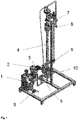
- FIG. 1 shows the expansion device described in WO 2014/198532 and WO 2016/091847 .
- the device comprises a hydraulic diaphragm pump, 1, connected to a heat exchanger, 4, forming a heating zone, and a pulsation damper, 2.
- the heat exchanger, 4, is provided with an inlet, 10, and an outlet, 8, in the form of a pipe provided with a flow area restriction at the end in the form of a nozzle.
- the heat exchanger, 4, further comprises one or a plurality of tubes (not shown) surrounded by a heat transfer medium (not shown) such as hot water, steam or oil.
- the device further comprises a pressure gauge, 3, a safety valve, 5, a control valve, 6, a thermometer, 7, and a three-way valve, 9.
- the device is operated by pumping a slurry of expandable microspheres, e.g. from a slurry tank (not shown), by means of the hydraulic diaphragm pump, 1, through the heat exchanger, 4, in which it is heated by the heat transfer medium to a temperature at which the microspheres start to expand or at least would have started to expand at atmospheric pressure.
- the hydraulic diaphragm pump, 1, creates a pressure sufficient for transporting the slurry through the heat exchanger, 4, and prohibiting complete expansion of the microspheres therein.
- the hot slurry flows out into the free air through outlet, 8, optionally provided with a flow area restriction, creating a pressure drop to atmospheric pressure, resulting in rapid expansion and cooling of the microspheres in free air.
- the pulsation damper, 2 inhibits fluctuations of the flow of the slurry from the hydraulic diaphragm pump 1.
- the pressure and the temperature in the heat exchanger can be monitored by the pressure gauge, 3, and the thermometer, 7, respectively.
- the equipment can be cleaned by exchanging the slurry of expandable microspheres for e.g. washing water with the aid of the 3-way valve, 9, prior to the pump, 1.
- the flow and pressure of the heat transfer medium used in the heat exchanger, 4, is regulated by the control valve, 6.
- Figure 2 shows a bagging station, 11, that can be connected to the above device, illustrating an embodiment of the back pressure generator mounted on it.
- the outlet of an expansion zone, 8 can be connected (optionally via a flexible tube) to the inlet, 12, of a distribution pipe, 13, (which is also shown in expanded form in the figure).
- the inlet, 12, connects to the distribution pipe, 13, at a point between a cooling medium inlet, 14, and the outlet of the distribution pipe, 15,.
- the outlet of the distribution pipe, 15, is connected to a cyclone separator, 16, on the bag stand, 17, for a bag (not shown) in which the fully expanded microparticles are collected.
- the cyclone separator, 16, comprises a ventilation outlet, 18.
- the back pressure generator in the exemplified embodiment comprises a flow restrictor adjuster, 19, that is placed in the distribution pipe and can be inserted to variable length into the flow of expanding particles. This will influence the back pressure generated in the expansion zone, 8, connected to inlet, 12.
- a water based slurry containing 20 wt% Expancel grade 461SLU40 microspheres and dispersion/stabilization additives is pumped with a pump providing a pressure of 20 bar through the heating zone (heat exchanger) of an expansion unit with a flow rate of 120 L/h.
- the slurry was heated to 131°C by means of the heat exchanger.
- the heated, expanding microsphere material was pushed through the outlet of the heating zone into into a wider outlet pipe (expansion zone, 250 cm long 4 cm wide) and subsequently entered a distribution pipe (24 cm long, 4 cm wide) where the material met a flow of cooling air (1,5 m 3 per minute) before exiting via a separation cyclone into a collector bag.
- Example 2 The procedure of Example 1 was repeated, except this time the slurry was heated to 120 °C, and the flow restrictor settings were 5 cm to 11 cm in the material flow. The pressure in the distribution zone was also measured. Results are shown in Table 2.
- Example 2 The procedure of Example 2 was repeated, except that a temperature of 122 °C was used, and the flow restrictor settings were 5 cm to 21 cm in the material flow. Results are shown in Table 3. Table 3. Properties of Expanded Expancel grade 461SLU40 at different settings for the flow restrictor Flow restrictor in flow (cm) Temperature °C Solid content wt% Pressure (bar) Density* g/L 5.0 122 22.0 1.2 21.6 9.2 122 22.1 2.8 27.2 15.0 122 22.1 3.3 32.5 20.7 122 22.1 3.4 33.1 * See Table 1
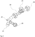
- Example 2 The procedure of Example 2 was repeated, except that the slurry was heated to 123 °C, and the flow restrictor was replaced by a flow valve, in order to build up the pressure in the distribution pipe.
- the distribution pipe, 20 comprises an inlet for the microspheres, 21, that connects to the outlet from the expansion zone. There is also an outlet for the microspheres, 22, and a cooling medium (air) inlet, 23.
- Flow valve, 24, was used to vary the pressure in the distribution zone, as measured by pressure gauge, 25. Results are shown in Table 4.
Landscapes
- Chemical & Material Sciences (AREA)
- Organic Chemistry (AREA)
- Chemical Kinetics & Catalysis (AREA)
- Dispersion Chemistry (AREA)
- Engineering & Computer Science (AREA)
- Materials Engineering (AREA)
- Health & Medical Sciences (AREA)
- Medicinal Chemistry (AREA)
- Polymers & Plastics (AREA)
- Manufacturing Of Micro-Capsules (AREA)
- Manufacture Of Porous Articles, And Recovery And Treatment Of Waste Products (AREA)
Claims (12)
- Vorrichtung zum Expandieren von unexpandierten, thermisch expandierbaren, thermoplastischen Mikrosphären, umfassend:- eine Erhitzungszone, die einen Einlass und einen Auslass aufweist,- eine Pumpe stromaufwärts von und in Fluidkommunikation mit der Erhitzungszone und dazu fähig, überatmosphärischen Druck in der Erhitzungszone zu erzeugen; und- Mittel zum Erhitzen der Erhitzungszone;- eine Expansionszone mit einem Einlass und einem Auslass, wobei der Einlass der Expansionszone mit dem Auslass der Erhitzungszone derart verbunden ist, dass ein Druckabfall derart verursacht wird, dass die Expansionszone sich bei einem niedereren Druck befindet als die Erhitzungszone, und- einen Rückdruckgenerator stromabwärts von der Expansionszone, der zum Verursachen eines variablen Gegendrucks in der Expansionszone konfiguriert ist.
- Vorrichtung nach Anspruch 1, wobei das Mittel zum Erhitzen der Aufschlämmung konfiguriert ist, die Inhalte der Erhitzungszone ohne direkten Kontakt mit irgendeinem fluiden Hitzeübertragungsmedium zu erhitzen.
- Vorrichtung nach Anspruch 1 oder Anspruch 2, wobei der Rückdruckgenerator ein Strömungsdrosselungseinsteller ist, der in oder hinter den Auslass der Expansionszone positioniert ist.
- Vorrichtung nach Anspruch 1 oder Anspruch 2, wobei die Expansionszone mit einem Stromabwärtsauslassrohr verbunden ist und das Auslassrohr durch eine Verbindung in ein Stromabwärtsverteilungsrohr strömen lässt, wobei das Verteilungsrohr stromaufwärts von der Verbindung auch einen Einlass für Kühlmedium aufweist.
- Vorrichtung nach Anspruch 4, wobei der Rückdruckgenerator einen Strömungseinsteller für die Strömung von Kühlmedium durch das Verteilungsrohr umfasst.
- Verfahren zum Expandieren von unexpandierten, thermisch expandierbaren, thermoplastischen Mikrosphären umfassend ein thermoplastisches Polymer, das ein Blasmittel einkapselt, wobei das Blasmittel eine Flüssigkeit ist, die eine Siedetemperatur von nicht höher als der Erweichungstemperatur des Mantels aus thermoplastischem Polymer aufweist, wobei das Verfahren Folgendes umfasst:- Einführen einer Aufschlämmung von unexpandierten, thermisch expandierbaren, thermoplastischen Mikrosphären in eine Erhitzungszone durch eine Pumpe, die dazu fähig ist, in der Erhitzungszone einen höheren als den atmosphärischen Druck zu erzeugen,- Erhitzen der Mikrosphären auf eine Temperatur über ihrer Erweichungstemperatur, während sie sich unter einem Druck befinden, der ausreichend hoch ist, sicherzustellen, dass sie sich nicht vollständig expandieren;- Führen der so erhitzten Mikrosphären aus der Erhitzungszone zu einer Expansionszone, derart, dass ein Druckabfall erzeugt wird, was zu einem Druck in der Expansionszone führt, der ausreichend niedrig ist, dass die Mikrosphären sich expandieren, und- Entfernen der expandierten Mikrosphären aus der Expansionszone,- wobei die Expansionszone zum Verursachen eines variablen Gegendrucks durch einen Rückdruckgenerator stromabwärts von der Expansionszone konfiguriert ist.
- Verfahren nach Anspruch 6, wobei der Druck, der in der Erhitzungszone aufrechterhalten wird, im Bereich von 10 bis 50 bar liegt.
- Verfahren nach Anspruch 6 oder Anspruch 7, wobei die Temperatur der Aufschlämmung in der Erhitzungszone im Bereich von 60 °C bis 250 °C liegt.
- Verfahren nach einem der Ansprüche 6 bis 8, wobei die Expansionszone mit einem Stromabwärtsauslassrohr verbunden ist und das Auslassrohr durch eine Verbindung in ein Stromabwärtsverteilungsrohr strömen lässt, wobei das Verteilungsrohr auch stromaufwärts von der Verbindung einen Einlass für Kühlmedium aufweist, wobei eine Strömung von Kühlmedium zu dem Einlass des Verteilungsrohrs geführt wird.
- Verfahren nach Anspruch 9, wobei das Kühlmedium eine Strömung von Gas, Flüssigkeit oder Teilchen ist, die bezüglich der expandierten thermoplastischen Mikrosphären inert sind.
- Verfahren nach Anspruch 10, wobei das Kühlmedium unter Luft, Wasser, Stickstoff, Kalkteilchen, Calciumcarbonatteilchen, Siliciumdioxidteilchen, Tonteilchen und TiO2-Teilchen oder einer Kombination davon ausgewählt wird.
- Verfahren nach einem der Ansprüche 6 bis 11, wobei die unexpandierten, thermisch expandierbaren, thermoplastischen Mikrosphären einer Vorrichtung wie in einem der Ansprüche 1 bis 5 beansprucht zugeführt werden.
Applications Claiming Priority (2)
| Application Number | Priority Date | Filing Date | Title |
|---|---|---|---|
| EP18165829 | 2018-04-05 | ||
| PCT/EP2019/058042 WO2019192936A1 (en) | 2018-04-05 | 2019-03-29 | Device for preparation of expanded microspheres |
Publications (2)
| Publication Number | Publication Date |
|---|---|
| EP3774259A1 EP3774259A1 (de) | 2021-02-17 |
| EP3774259B1 true EP3774259B1 (de) | 2022-09-07 |
Family
ID=61906729
Family Applications (1)
| Application Number | Title | Priority Date | Filing Date |
|---|---|---|---|
| EP19713065.1A Active EP3774259B1 (de) | 2018-04-05 | 2019-03-29 | Vorrichtung und verfahren zur herstellung von expandierten mikrokugeln |
Country Status (11)
| Country | Link |
|---|---|
| US (1) | US12226938B2 (de) |
| EP (1) | EP3774259B1 (de) |
| JP (1) | JP7377213B2 (de) |
| KR (1) | KR102732857B1 (de) |
| CN (1) | CN112533746B (de) |
| AU (1) | AU2019248573B2 (de) |
| CA (1) | CA3095670A1 (de) |
| ES (1) | ES2930560T3 (de) |
| PL (1) | PL3774259T3 (de) |
| PT (1) | PT3774259T (de) |
| WO (1) | WO2019192936A1 (de) |
Families Citing this family (3)
| Publication number | Priority date | Publication date | Assignee | Title |
|---|---|---|---|---|
| EP4067420A4 (de) * | 2019-11-29 | 2023-12-20 | Kaneka Corporation | Vorrichtung und verfahren zur herstellung von expandierten partikeln |
| KR102562880B1 (ko) * | 2021-03-18 | 2023-08-03 | 순천향대학교 산학협력단 | 양자점의 연속 대량 합성방법 및 이에 이용되는 양자점 연속 대량 합성장치 |
| CN116160354A (zh) * | 2023-02-14 | 2023-05-26 | 上海芯谦集成电路有限公司 | 一种聚合物微球体的处理方法和设备 |
Family Cites Families (35)
| Publication number | Priority date | Publication date | Assignee | Title |
|---|---|---|---|---|
| US3615972A (en) | 1967-04-28 | 1971-10-26 | Dow Chemical Co | Expansible thermoplastic polymer particles containing volatile fluid foaming agent and method of foaming the same |
| US3945956A (en) | 1975-06-23 | 1976-03-23 | The Dow Chemical Company | Polymerization of styrene acrylonitrile expandable microspheres |
| JPS6021770B2 (ja) | 1980-02-14 | 1985-05-29 | 松本油脂製薬株式会社 | 熱膨張性マイクロカプセルの製造法 |
| SE452471B (sv) | 1982-11-26 | 1987-11-30 | Casco Nobel Ab | Forfarande for expandering av termoplastiska mikrosferer |
| JPS62286534A (ja) | 1986-06-04 | 1987-12-12 | Matsumoto Yushi Seiyaku Kk | 熱膨張性マイクロカプセルの製造法 |
| ATE101823T1 (de) | 1988-06-23 | 1994-03-15 | Casco Nobel Ab | Verfahren und vorrichtung zur herstellung expandierbarer thermoplastischer mikrokugeln. |
| SE9003600L (sv) | 1990-11-12 | 1992-05-13 | Casco Nobel Ab | Expanderbara termoplastiska mikrosfaerer samt foerfarande foer framstaellning daerav |
| JP3659979B2 (ja) | 1992-04-15 | 2005-06-15 | 松本油脂製薬株式会社 | 熱膨張性マイクロカプセルとその製法 |
| US5977195A (en) * | 1997-08-01 | 1999-11-02 | Huntsman Corporation | Expandable thermoplastic polymer particles and method for making same |
| EP1059339B1 (de) | 1998-02-24 | 2004-10-13 | Matsumoto Yushi-Seiyaku Co., Ltd. | Wärmeausdehnbare mikrokapseln, verfahren zur herstellung und verwendung derselben |
| EP1067151B1 (de) | 1998-03-13 | 2003-12-17 | Matsumoto Yushi-Seiyaku Co., Ltd. | Hitzeexpandierbare mikrokapseln und verfahren zu deren verwendung |
| US6365641B1 (en) | 1999-09-29 | 2002-04-02 | Matsumoto Yushi-Seiyaku Co Ltd | Process for producing heat-expandable microcapsules |
| EP1288272B2 (de) | 2000-04-28 | 2016-04-13 | Kureha Corporation | Thermisch ausdehnbare mikroteilchen und verfahren zu ihrer herstellung |
| US6509384B2 (en) | 2000-04-28 | 2003-01-21 | Akzo Nobel N.V. | Chemical product and method |
| US6617363B2 (en) | 2001-01-18 | 2003-09-09 | Sekisui Chemical Co., Ltd. | Method of producing thermally expansive microcapsule |
| CA2446885A1 (en) | 2001-05-25 | 2002-12-05 | Apache Products Company | Foam insulation made with expandable microspheres and methods |
| JP4393377B2 (ja) | 2002-05-24 | 2010-01-06 | 松本油脂製薬株式会社 | 熱膨張性マイクロカプセルおよびその利用 |
| US7192989B2 (en) | 2002-12-20 | 2007-03-20 | Akzo Nobel N.V. | Method and expansion device for preparing expanded thermoplastic microspheres |
| JP4099077B2 (ja) * | 2003-02-03 | 2008-06-11 | 積水化学工業株式会社 | 熱膨張済みマイクロカプセルの製造装置及び熱膨張済みマイクロカプセルの製造方法 |
| CN100354346C (zh) | 2003-02-11 | 2007-12-12 | 阿克佐诺贝尔公司 | 微球体 |
| KR101004337B1 (ko) | 2003-02-24 | 2010-12-28 | 마쓰모토유시세이야쿠 가부시키가이샤 | 열팽창성 미소구, 그 제조 방법 및 그 사용 방법 |
| JP2005272633A (ja) | 2004-03-24 | 2005-10-06 | Sanyo Chem Ind Ltd | 中空樹脂粒子及び熱膨張性マイクロカプセル |
| JP4945243B2 (ja) | 2004-09-13 | 2012-06-06 | 株式会社クレハ | 熱発泡性マイクロスフェアー、その製造方法、その使用、それを含む組成物、及び物品 |
| KR101533203B1 (ko) | 2005-12-19 | 2015-07-02 | 가부시끼가이샤 구레하 | 열발포성 마이크로스페어, 그리고 그 제조 방법과 용도 |
| RU2432989C2 (ru) | 2006-02-10 | 2011-11-10 | Акцо Нобель Н.В. | Микросферы |
| PL1981630T3 (pl) | 2006-02-10 | 2016-03-31 | Akzo Nobel Chemicals Int Bv | Mikrosfery |
| ES2605418T3 (es) | 2006-06-08 | 2017-03-14 | Akzo Nobel N.V. | Microesferas |
| US9333685B2 (en) * | 2012-04-19 | 2016-05-10 | AkzoNobel Chemicals International B.V. | Apparatus and system for expanding expandable polymeric microspheres |
| US9150452B2 (en) * | 2012-04-19 | 2015-10-06 | Construction Research & Technology, Gmbh | Method for manufacturing a cementitious composition |
| MX2014012605A (es) * | 2012-04-19 | 2015-06-02 | Constr Res & Tech Gmbh | Aparato y sistema para expandir microesferas polimericas expandibles. |
| DK3008029T3 (en) | 2013-06-12 | 2017-07-24 | Akzo Nobel Chemicals Int Bv | METHOD AND APPARATUS FOR MANUFACTURING EXPANDED MICROSphere |
| CA2969302C (en) * | 2014-12-11 | 2023-02-28 | Akzo Nobel Chemicals International B.V. | Apparatus and method for expanding thermally expandable thermoplastic microspheres |
| CN107257822B (zh) | 2014-12-11 | 2020-11-10 | 建筑研究和技术有限公司 | 用于使可膨胀性聚合物微球膨胀的装置和系统 |
| WO2016091847A1 (en) * | 2014-12-11 | 2016-06-16 | Akzo Nobel Chemicals International B.V. | Apparatus and method for expanding thermally expandable thermoplastic microspheres to expanded thermoplastic microspheres |
| WO2016091742A1 (en) * | 2014-12-11 | 2016-06-16 | Construction Research & Technology Gmbh | Method for manufacturing cement containing expanded polymeric microspheres |
-
2019
- 2019-03-29 EP EP19713065.1A patent/EP3774259B1/de active Active
- 2019-03-29 PL PL19713065.1T patent/PL3774259T3/pl unknown
- 2019-03-29 AU AU2019248573A patent/AU2019248573B2/en active Active
- 2019-03-29 CN CN201980037656.1A patent/CN112533746B/zh active Active
- 2019-03-29 US US17/045,388 patent/US12226938B2/en active Active
- 2019-03-29 PT PT197130651T patent/PT3774259T/pt unknown
- 2019-03-29 KR KR1020207031987A patent/KR102732857B1/ko active Active
- 2019-03-29 CA CA3095670A patent/CA3095670A1/en active Pending
- 2019-03-29 WO PCT/EP2019/058042 patent/WO2019192936A1/en not_active Ceased
- 2019-03-29 JP JP2020554274A patent/JP7377213B2/ja active Active
- 2019-03-29 ES ES19713065T patent/ES2930560T3/es active Active
Also Published As
| Publication number | Publication date |
|---|---|
| BR112020020175A2 (pt) | 2021-01-05 |
| EP3774259A1 (de) | 2021-02-17 |
| US12226938B2 (en) | 2025-02-18 |
| AU2019248573B2 (en) | 2024-09-05 |
| US20210146580A1 (en) | 2021-05-20 |
| PT3774259T (pt) | 2022-11-28 |
| JP7377213B2 (ja) | 2023-11-09 |
| WO2019192936A1 (en) | 2019-10-10 |
| JP2021523248A (ja) | 2021-09-02 |
| CN112533746A (zh) | 2021-03-19 |
| RU2020136083A (ru) | 2022-05-06 |
| CA3095670A1 (en) | 2019-10-10 |
| ES2930560T3 (es) | 2022-12-16 |
| CN112533746B (zh) | 2023-04-18 |
| RU2020136083A3 (de) | 2022-05-06 |
| KR102732857B1 (ko) | 2024-11-20 |
| AU2019248573A1 (en) | 2020-10-15 |
| KR20210016340A (ko) | 2021-02-15 |
| PL3774259T3 (pl) | 2022-12-27 |
Similar Documents
| Publication | Publication Date | Title |
|---|---|---|
| EP3008029B1 (de) | Verfahren und vorrichtung zur herstellung erweiterter mikrokugeln | |
| EP3774259B1 (de) | Vorrichtung und verfahren zur herstellung von expandierten mikrokugeln | |
| EP3230224B1 (de) | Vorrichtung und verfahren für thermisch ausdehnbare thermoplastische mikrokugeln zu ausdehnbaren thermoplastischen mikrokugeln | |
| US10214624B2 (en) | Apparatus and method for expanding thermally expandable thermoplastic microspheres to expanded thermoplastic microspheres | |
| RU2771821C2 (ru) | Устройство для получения вспененных микросфер | |
| BR112020020175B1 (pt) | Dispositivo e processo de expansão de microesferas termoplásticas termicamente expansíveis não expandidas | |
| TW201632257A (zh) | 用於將熱可膨脹的熱塑性微球體膨脹成經膨脹的熱塑性微球體之裝置及方法 |
Legal Events
| Date | Code | Title | Description |
|---|---|---|---|
| STAA | Information on the status of an ep patent application or granted ep patent |
Free format text: STATUS: UNKNOWN |
|
| STAA | Information on the status of an ep patent application or granted ep patent |
Free format text: STATUS: THE INTERNATIONAL PUBLICATION HAS BEEN MADE |
|
| PUAI | Public reference made under article 153(3) epc to a published international application that has entered the european phase |
Free format text: ORIGINAL CODE: 0009012 |
|
| STAA | Information on the status of an ep patent application or granted ep patent |
Free format text: STATUS: REQUEST FOR EXAMINATION WAS MADE |
|
| 17P | Request for examination filed |
Effective date: 20201009 |
|
| AK | Designated contracting states |
Kind code of ref document: A1 Designated state(s): AL AT BE BG CH CY CZ DE DK EE ES FI FR GB GR HR HU IE IS IT LI LT LU LV MC MK MT NL NO PL PT RO RS SE SI SK SM TR |
|
| AX | Request for extension of the european patent |
Extension state: BA ME |
|
| DAV | Request for validation of the european patent (deleted) | ||
| DAX | Request for extension of the european patent (deleted) | ||
| GRAP | Despatch of communication of intention to grant a patent |
Free format text: ORIGINAL CODE: EPIDOSNIGR1 |
|
| STAA | Information on the status of an ep patent application or granted ep patent |
Free format text: STATUS: GRANT OF PATENT IS INTENDED |
|
| INTG | Intention to grant announced |
Effective date: 20220407 |
|
| GRAS | Grant fee paid |
Free format text: ORIGINAL CODE: EPIDOSNIGR3 |
|
| GRAA | (expected) grant |
Free format text: ORIGINAL CODE: 0009210 |
|
| STAA | Information on the status of an ep patent application or granted ep patent |
Free format text: STATUS: THE PATENT HAS BEEN GRANTED |
|
| AK | Designated contracting states |
Kind code of ref document: B1 Designated state(s): AL AT BE BG CH CY CZ DE DK EE ES FI FR GB GR HR HU IE IS IT LI LT LU LV MC MK MT NL NO PL PT RO RS SE SI SK SM TR |
|
| REG | Reference to a national code |
Ref country code: GB Ref legal event code: FG4D |
|
| REG | Reference to a national code |
Ref country code: CH Ref legal event code: EP Ref country code: AT Ref legal event code: REF Ref document number: 1516665 Country of ref document: AT Kind code of ref document: T Effective date: 20220915 |
|
| REG | Reference to a national code |
Ref country code: IE Ref legal event code: FG4D |
|
| REG | Reference to a national code |
Ref country code: DE Ref legal event code: R096 Ref document number: 602019019251 Country of ref document: DE |
|
| REG | Reference to a national code |
Ref country code: PT Ref legal event code: SC4A Ref document number: 3774259 Country of ref document: PT Date of ref document: 20221128 Kind code of ref document: T Free format text: AVAILABILITY OF NATIONAL TRANSLATION Effective date: 20221122 |
|
| REG | Reference to a national code |
Ref country code: NL Ref legal event code: FP |
|
| REG | Reference to a national code |
Ref country code: ES Ref legal event code: FG2A Ref document number: 2930560 Country of ref document: ES Kind code of ref document: T3 Effective date: 20221216 |
|
| REG | Reference to a national code |
Ref country code: LT Ref legal event code: MG9D |
|
| PG25 | Lapsed in a contracting state [announced via postgrant information from national office to epo] |
Ref country code: SE Free format text: LAPSE BECAUSE OF FAILURE TO SUBMIT A TRANSLATION OF THE DESCRIPTION OR TO PAY THE FEE WITHIN THE PRESCRIBED TIME-LIMIT Effective date: 20220907 Ref country code: RS Free format text: LAPSE BECAUSE OF FAILURE TO SUBMIT A TRANSLATION OF THE DESCRIPTION OR TO PAY THE FEE WITHIN THE PRESCRIBED TIME-LIMIT Effective date: 20220907 Ref country code: NO Free format text: LAPSE BECAUSE OF FAILURE TO SUBMIT A TRANSLATION OF THE DESCRIPTION OR TO PAY THE FEE WITHIN THE PRESCRIBED TIME-LIMIT Effective date: 20221207 Ref country code: LV Free format text: LAPSE BECAUSE OF FAILURE TO SUBMIT A TRANSLATION OF THE DESCRIPTION OR TO PAY THE FEE WITHIN THE PRESCRIBED TIME-LIMIT Effective date: 20220907 Ref country code: LT Free format text: LAPSE BECAUSE OF FAILURE TO SUBMIT A TRANSLATION OF THE DESCRIPTION OR TO PAY THE FEE WITHIN THE PRESCRIBED TIME-LIMIT Effective date: 20220907 Ref country code: FI Free format text: LAPSE BECAUSE OF FAILURE TO SUBMIT A TRANSLATION OF THE DESCRIPTION OR TO PAY THE FEE WITHIN THE PRESCRIBED TIME-LIMIT Effective date: 20220907 |
|
| REG | Reference to a national code |
Ref country code: AT Ref legal event code: MK05 Ref document number: 1516665 Country of ref document: AT Kind code of ref document: T Effective date: 20220907 |
|
| PG25 | Lapsed in a contracting state [announced via postgrant information from national office to epo] |
Ref country code: HR Free format text: LAPSE BECAUSE OF FAILURE TO SUBMIT A TRANSLATION OF THE DESCRIPTION OR TO PAY THE FEE WITHIN THE PRESCRIBED TIME-LIMIT Effective date: 20220907 Ref country code: GR Free format text: LAPSE BECAUSE OF FAILURE TO SUBMIT A TRANSLATION OF THE DESCRIPTION OR TO PAY THE FEE WITHIN THE PRESCRIBED TIME-LIMIT Effective date: 20221208 |
|
| PG25 | Lapsed in a contracting state [announced via postgrant information from national office to epo] |
Ref country code: SM Free format text: LAPSE BECAUSE OF FAILURE TO SUBMIT A TRANSLATION OF THE DESCRIPTION OR TO PAY THE FEE WITHIN THE PRESCRIBED TIME-LIMIT Effective date: 20220907 Ref country code: RO Free format text: LAPSE BECAUSE OF FAILURE TO SUBMIT A TRANSLATION OF THE DESCRIPTION OR TO PAY THE FEE WITHIN THE PRESCRIBED TIME-LIMIT Effective date: 20220907 Ref country code: AT Free format text: LAPSE BECAUSE OF FAILURE TO SUBMIT A TRANSLATION OF THE DESCRIPTION OR TO PAY THE FEE WITHIN THE PRESCRIBED TIME-LIMIT Effective date: 20220907 |
|
| PGFP | Annual fee paid to national office [announced via postgrant information from national office to epo] |
Ref country code: CZ Payment date: 20230307 Year of fee payment: 5 |
|
| PG25 | Lapsed in a contracting state [announced via postgrant information from national office to epo] |
Ref country code: SK Free format text: LAPSE BECAUSE OF FAILURE TO SUBMIT A TRANSLATION OF THE DESCRIPTION OR TO PAY THE FEE WITHIN THE PRESCRIBED TIME-LIMIT Effective date: 20220907 Ref country code: IS Free format text: LAPSE BECAUSE OF FAILURE TO SUBMIT A TRANSLATION OF THE DESCRIPTION OR TO PAY THE FEE WITHIN THE PRESCRIBED TIME-LIMIT Effective date: 20230107 Ref country code: EE Free format text: LAPSE BECAUSE OF FAILURE TO SUBMIT A TRANSLATION OF THE DESCRIPTION OR TO PAY THE FEE WITHIN THE PRESCRIBED TIME-LIMIT Effective date: 20220907 |
|
| PGFP | Annual fee paid to national office [announced via postgrant information from national office to epo] |
Ref country code: BE Payment date: 20230327 Year of fee payment: 5 |
|
| REG | Reference to a national code |
Ref country code: DE Ref legal event code: R097 Ref document number: 602019019251 Country of ref document: DE |
|
| PG25 | Lapsed in a contracting state [announced via postgrant information from national office to epo] |
Ref country code: AL Free format text: LAPSE BECAUSE OF FAILURE TO SUBMIT A TRANSLATION OF THE DESCRIPTION OR TO PAY THE FEE WITHIN THE PRESCRIBED TIME-LIMIT Effective date: 20220907 |
|
| PGFP | Annual fee paid to national office [announced via postgrant information from national office to epo] |
Ref country code: NL Payment date: 20230326 Year of fee payment: 5 |
|
| P01 | Opt-out of the competence of the unified patent court (upc) registered |
Effective date: 20230601 |
|
| PLBE | No opposition filed within time limit |
Free format text: ORIGINAL CODE: 0009261 |
|
| STAA | Information on the status of an ep patent application or granted ep patent |
Free format text: STATUS: NO OPPOSITION FILED WITHIN TIME LIMIT |
|
| PG25 | Lapsed in a contracting state [announced via postgrant information from national office to epo] |
Ref country code: DK Free format text: LAPSE BECAUSE OF FAILURE TO SUBMIT A TRANSLATION OF THE DESCRIPTION OR TO PAY THE FEE WITHIN THE PRESCRIBED TIME-LIMIT Effective date: 20220907 |
|
| 26N | No opposition filed |
Effective date: 20230608 |
|
| PG25 | Lapsed in a contracting state [announced via postgrant information from national office to epo] |
Ref country code: SI Free format text: LAPSE BECAUSE OF FAILURE TO SUBMIT A TRANSLATION OF THE DESCRIPTION OR TO PAY THE FEE WITHIN THE PRESCRIBED TIME-LIMIT Effective date: 20220907 |
|
| PG25 | Lapsed in a contracting state [announced via postgrant information from national office to epo] |
Ref country code: MC Free format text: LAPSE BECAUSE OF FAILURE TO SUBMIT A TRANSLATION OF THE DESCRIPTION OR TO PAY THE FEE WITHIN THE PRESCRIBED TIME-LIMIT Effective date: 20220907 |
|
| PG25 | Lapsed in a contracting state [announced via postgrant information from national office to epo] |
Ref country code: LU Free format text: LAPSE BECAUSE OF NON-PAYMENT OF DUE FEES Effective date: 20230329 |
|
| REG | Reference to a national code |
Ref country code: IE Ref legal event code: MM4A |
|
| PG25 | Lapsed in a contracting state [announced via postgrant information from national office to epo] |
Ref country code: IE Free format text: LAPSE BECAUSE OF NON-PAYMENT OF DUE FEES Effective date: 20230329 |
|
| REG | Reference to a national code |
Ref country code: NL Ref legal event code: PD Owner name: NOURYON CHEMICALS INTERNATIONAL B.V.; NL Free format text: DETAILS ASSIGNMENT: CHANGE OF OWNER(S), ASSIGNMENT; FORMER OWNER NAME: NOURYON CHEMICALS INTERNATIONAL B.V. Effective date: 20240412 |
|
| REG | Reference to a national code |
Ref country code: BE Ref legal event code: PD Owner name: NOURYON CHEMICALS INTERNATIONAL B.V.; NL Free format text: DETAILS ASSIGNMENT: CHANGE OF OWNER(S), ASSIGNMENT; FORMER OWNER NAME: CONSTRUCTION RESEARCH & TECHNOLOGY GMBH Effective date: 20240425 |
|
| PG25 | Lapsed in a contracting state [announced via postgrant information from national office to epo] |
Ref country code: CZ Free format text: LAPSE BECAUSE OF NON-PAYMENT OF DUE FEES Effective date: 20240329 |
|
| PG25 | Lapsed in a contracting state [announced via postgrant information from national office to epo] |
Ref country code: CZ Free format text: LAPSE BECAUSE OF NON-PAYMENT OF DUE FEES Effective date: 20240329 |
|
| REG | Reference to a national code |
Ref country code: NL Ref legal event code: MM Effective date: 20240401 |
|
| PG25 | Lapsed in a contracting state [announced via postgrant information from national office to epo] |
Ref country code: BG Free format text: LAPSE BECAUSE OF FAILURE TO SUBMIT A TRANSLATION OF THE DESCRIPTION OR TO PAY THE FEE WITHIN THE PRESCRIBED TIME-LIMIT Effective date: 20220907 |
|
| PG25 | Lapsed in a contracting state [announced via postgrant information from national office to epo] |
Ref country code: BG Free format text: LAPSE BECAUSE OF FAILURE TO SUBMIT A TRANSLATION OF THE DESCRIPTION OR TO PAY THE FEE WITHIN THE PRESCRIBED TIME-LIMIT Effective date: 20220907 |
|
| PG25 | Lapsed in a contracting state [announced via postgrant information from national office to epo] |
Ref country code: NL Free format text: LAPSE BECAUSE OF NON-PAYMENT OF DUE FEES Effective date: 20240401 |
|
| REG | Reference to a national code |
Ref country code: BE Ref legal event code: MM Effective date: 20240331 |
|
| PG25 | Lapsed in a contracting state [announced via postgrant information from national office to epo] |
Ref country code: NL Free format text: LAPSE BECAUSE OF NON-PAYMENT OF DUE FEES Effective date: 20240401 |
|
| PG25 | Lapsed in a contracting state [announced via postgrant information from national office to epo] |
Ref country code: BE Free format text: LAPSE BECAUSE OF NON-PAYMENT OF DUE FEES Effective date: 20240331 |
|
| PG25 | Lapsed in a contracting state [announced via postgrant information from national office to epo] |
Ref country code: BE Free format text: LAPSE BECAUSE OF NON-PAYMENT OF DUE FEES Effective date: 20240331 |
|
| PGFP | Annual fee paid to national office [announced via postgrant information from national office to epo] |
Ref country code: DE Payment date: 20250327 Year of fee payment: 7 |
|
| PGFP | Annual fee paid to national office [announced via postgrant information from national office to epo] |
Ref country code: FR Payment date: 20250325 Year of fee payment: 7 |
|
| PGFP | Annual fee paid to national office [announced via postgrant information from national office to epo] |
Ref country code: GB Payment date: 20250327 Year of fee payment: 7 |
|
| PG25 | Lapsed in a contracting state [announced via postgrant information from national office to epo] |
Ref country code: CY Free format text: LAPSE BECAUSE OF FAILURE TO SUBMIT A TRANSLATION OF THE DESCRIPTION OR TO PAY THE FEE WITHIN THE PRESCRIBED TIME-LIMIT; INVALID AB INITIO Effective date: 20190329 |
|
| PG25 | Lapsed in a contracting state [announced via postgrant information from national office to epo] |
Ref country code: HU Free format text: LAPSE BECAUSE OF FAILURE TO SUBMIT A TRANSLATION OF THE DESCRIPTION OR TO PAY THE FEE WITHIN THE PRESCRIBED TIME-LIMIT; INVALID AB INITIO Effective date: 20190329 |
|
| PGFP | Annual fee paid to national office [announced via postgrant information from national office to epo] |
Ref country code: ES Payment date: 20250901 Year of fee payment: 7 Ref country code: PT Payment date: 20250902 Year of fee payment: 7 |
|
| PGFP | Annual fee paid to national office [announced via postgrant information from national office to epo] |
Ref country code: TR Payment date: 20250904 Year of fee payment: 7 Ref country code: PL Payment date: 20250902 Year of fee payment: 7 Ref country code: IT Payment date: 20250901 Year of fee payment: 7 |
|
| PGFP | Annual fee paid to national office [announced via postgrant information from national office to epo] |
Ref country code: CH Payment date: 20250827 Year of fee payment: 7 |