EP3774186B1 - Pré-assemblage de pièces - Google Patents
Pré-assemblage de pièces Download PDFInfo
- Publication number
- EP3774186B1 EP3774186B1 EP19719350.1A EP19719350A EP3774186B1 EP 3774186 B1 EP3774186 B1 EP 3774186B1 EP 19719350 A EP19719350 A EP 19719350A EP 3774186 B1 EP3774186 B1 EP 3774186B1
- Authority
- EP
- European Patent Office
- Prior art keywords
- assembly
- stack
- flexible securing
- ship
- securing sheet
- Prior art date
- Legal status (The legal status is an assumption and is not a legal conclusion. Google has not performed a legal analysis and makes no representation as to the accuracy of the status listed.)
- Active
Links
Images


Classifications
-
- B—PERFORMING OPERATIONS; TRANSPORTING
- B25—HAND TOOLS; PORTABLE POWER-DRIVEN TOOLS; MANIPULATORS
- B25B—TOOLS OR BENCH DEVICES NOT OTHERWISE PROVIDED FOR, FOR FASTENING, CONNECTING, DISENGAGING, OR HOLDING
- B25B27/00—Hand tools, specially adapted for fitting together or separating parts or objects whether or not involving some deformation, not otherwise provided for
- B25B27/0035—Hand tools, specially adapted for fitting together or separating parts or objects whether or not involving some deformation, not otherwise provided for for motor-vehicles
- B25B27/0064—Hand tools, specially adapted for fitting together or separating parts or objects whether or not involving some deformation, not otherwise provided for for motor-vehicles for assembling or disassembling clutches
-
- B—PERFORMING OPERATIONS; TRANSPORTING
- B23—MACHINE TOOLS; METAL-WORKING NOT OTHERWISE PROVIDED FOR
- B23P—METAL-WORKING NOT OTHERWISE PROVIDED FOR; COMBINED OPERATIONS; UNIVERSAL MACHINE TOOLS
- B23P19/00—Machines for simply fitting together or separating metal parts or objects, or metal and non-metal parts, whether or not involving some deformation; Tools or devices therefor so far as not provided for in other classes
- B23P19/04—Machines for simply fitting together or separating metal parts or objects, or metal and non-metal parts, whether or not involving some deformation; Tools or devices therefor so far as not provided for in other classes for assembling or disassembling parts
- B23P19/08—Machines for placing washers, circlips, or the like on bolts or other members
-
- B—PERFORMING OPERATIONS; TRANSPORTING
- B25—HAND TOOLS; PORTABLE POWER-DRIVEN TOOLS; MANIPULATORS
- B25B—TOOLS OR BENCH DEVICES NOT OTHERWISE PROVIDED FOR, FOR FASTENING, CONNECTING, DISENGAGING, OR HOLDING
- B25B27/00—Hand tools, specially adapted for fitting together or separating parts or objects whether or not involving some deformation, not otherwise provided for
- B25B27/14—Hand tools, specially adapted for fitting together or separating parts or objects whether or not involving some deformation, not otherwise provided for for assembling objects other than by press fit or detaching same
-
- F—MECHANICAL ENGINEERING; LIGHTING; HEATING; WEAPONS; BLASTING
- F17—STORING OR DISTRIBUTING GASES OR LIQUIDS
- F17C—VESSELS FOR CONTAINING OR STORING COMPRESSED, LIQUEFIED OR SOLIDIFIED GASES; FIXED-CAPACITY GAS-HOLDERS; FILLING VESSELS WITH, OR DISCHARGING FROM VESSELS, COMPRESSED, LIQUEFIED, OR SOLIDIFIED GASES
- F17C13/00—Details of vessels or of the filling or discharging of vessels
-
- B—PERFORMING OPERATIONS; TRANSPORTING
- B63—SHIPS OR OTHER WATERBORNE VESSELS; RELATED EQUIPMENT
- B63B—SHIPS OR OTHER WATERBORNE VESSELS; EQUIPMENT FOR SHIPPING
- B63B25/00—Load-accommodating arrangements, e.g. stowing, trimming; Vessels characterised thereby
- B63B25/02—Load-accommodating arrangements, e.g. stowing, trimming; Vessels characterised thereby for bulk goods
- B63B25/08—Load-accommodating arrangements, e.g. stowing, trimming; Vessels characterised thereby for bulk goods fluid
- B63B25/12—Load-accommodating arrangements, e.g. stowing, trimming; Vessels characterised thereby for bulk goods fluid closed
- B63B25/16—Load-accommodating arrangements, e.g. stowing, trimming; Vessels characterised thereby for bulk goods fluid closed heat-insulated
-
- F—MECHANICAL ENGINEERING; LIGHTING; HEATING; WEAPONS; BLASTING
- F17—STORING OR DISTRIBUTING GASES OR LIQUIDS
- F17C—VESSELS FOR CONTAINING OR STORING COMPRESSED, LIQUEFIED OR SOLIDIFIED GASES; FIXED-CAPACITY GAS-HOLDERS; FILLING VESSELS WITH, OR DISCHARGING FROM VESSELS, COMPRESSED, LIQUEFIED, OR SOLIDIFIED GASES
- F17C2203/00—Vessel construction, in particular walls or details thereof
- F17C2203/03—Thermal insulations
- F17C2203/0304—Thermal insulations by solid means
-
- F—MECHANICAL ENGINEERING; LIGHTING; HEATING; WEAPONS; BLASTING
- F17—STORING OR DISTRIBUTING GASES OR LIQUIDS
- F17C—VESSELS FOR CONTAINING OR STORING COMPRESSED, LIQUEFIED OR SOLIDIFIED GASES; FIXED-CAPACITY GAS-HOLDERS; FILLING VESSELS WITH, OR DISCHARGING FROM VESSELS, COMPRESSED, LIQUEFIED, OR SOLIDIFIED GASES
- F17C2209/00—Vessel construction, in particular methods of manufacturing
- F17C2209/23—Manufacturing of particular parts or at special locations
- F17C2209/232—Manufacturing of particular parts or at special locations of walls
-
- F—MECHANICAL ENGINEERING; LIGHTING; HEATING; WEAPONS; BLASTING
- F17—STORING OR DISTRIBUTING GASES OR LIQUIDS
- F17C—VESSELS FOR CONTAINING OR STORING COMPRESSED, LIQUEFIED OR SOLIDIFIED GASES; FIXED-CAPACITY GAS-HOLDERS; FILLING VESSELS WITH, OR DISCHARGING FROM VESSELS, COMPRESSED, LIQUEFIED, OR SOLIDIFIED GASES
- F17C2221/00—Handled fluid, in particular type of fluid
- F17C2221/03—Mixtures
- F17C2221/032—Hydrocarbons
- F17C2221/033—Methane, e.g. natural gas, CNG, LNG, GNL, GNC, PLNG
-
- F—MECHANICAL ENGINEERING; LIGHTING; HEATING; WEAPONS; BLASTING
- F17—STORING OR DISTRIBUTING GASES OR LIQUIDS
- F17C—VESSELS FOR CONTAINING OR STORING COMPRESSED, LIQUEFIED OR SOLIDIFIED GASES; FIXED-CAPACITY GAS-HOLDERS; FILLING VESSELS WITH, OR DISCHARGING FROM VESSELS, COMPRESSED, LIQUEFIED, OR SOLIDIFIED GASES
- F17C2223/00—Handled fluid before transfer, i.e. state of fluid when stored in the vessel or before transfer from the vessel
- F17C2223/01—Handled fluid before transfer, i.e. state of fluid when stored in the vessel or before transfer from the vessel characterised by the phase
- F17C2223/0146—Two-phase
- F17C2223/0153—Liquefied gas, e.g. LPG, GPL
- F17C2223/0161—Liquefied gas, e.g. LPG, GPL cryogenic, e.g. LNG, GNL, PLNG
-
- F—MECHANICAL ENGINEERING; LIGHTING; HEATING; WEAPONS; BLASTING
- F17—STORING OR DISTRIBUTING GASES OR LIQUIDS
- F17C—VESSELS FOR CONTAINING OR STORING COMPRESSED, LIQUEFIED OR SOLIDIFIED GASES; FIXED-CAPACITY GAS-HOLDERS; FILLING VESSELS WITH, OR DISCHARGING FROM VESSELS, COMPRESSED, LIQUEFIED, OR SOLIDIFIED GASES
- F17C2270/00—Applications
- F17C2270/01—Applications for fluid transport or storage
- F17C2270/0102—Applications for fluid transport or storage on or in the water
- F17C2270/0105—Ships
- F17C2270/0107—Wall panels
-
- F—MECHANICAL ENGINEERING; LIGHTING; HEATING; WEAPONS; BLASTING
- F17—STORING OR DISTRIBUTING GASES OR LIQUIDS
- F17C—VESSELS FOR CONTAINING OR STORING COMPRESSED, LIQUEFIED OR SOLIDIFIED GASES; FIXED-CAPACITY GAS-HOLDERS; FILLING VESSELS WITH, OR DISCHARGING FROM VESSELS, COMPRESSED, LIQUEFIED, OR SOLIDIFIED GASES
- F17C3/00—Vessels not under pressure
Definitions
- the present invention relates to the field of mechanical assemblies and more particularly those comprising a shaft, such as a smooth or threaded rod (stud), on which a plurality of parts are mounted. These parts are pierced with a hole, of section substantially corresponding to the section of the shaft, so as to accommodate said shaft. These parts can be chosen from: washer, spacer, seal, spring, nut, or other.
- a shaft such as a smooth or threaded rod (stud)
- stud threaded rod
- These parts are pierced with a hole, of section substantially corresponding to the section of the shaft, so as to accommodate said shaft.
- These parts can be chosen from: washer, spacer, seal, spring, nut, or other.
- each of the plurality of parts is engaged on the shaft.
- the type, orientation and number of each part must be respected. This can be difficult when the assembly is carried out in conditions of poor lighting, lack of space, difficulty of positioning, difficulty of access or mobility (vehicle, floating platform, etc.). Such conditions
- the document EP1834893 describes a pre-assembly and a method of manufacturing a pre-assembly according to the preambles of claims 1 and 14 respectively. It describes in particular a sheath for the packaging of round seals. The sheath is sealed longitudinally and laterally by lines of welds. The sheath includes pre-cuts between the weld lines and the seals to allow the sheath to be removed after placing the sheath and seal assembly in a distributor tube.
- An idea underlying the invention is to propose a pre-assembly comprising all or part of the parts intended to be mounted on a shaft, in type, orientation and number adapted to the needs of the assembly, joined together in a single object, in order to make them easier to handle.
- the invention relates to a pre-assembly of parts suitable for being mounted on a shaft according to independent claim 1.
- the flexible securing ply comprises a plastic film.
- the flexible sheet of connection comprises a heat-shrink sheath.
- the flexible securing ply is spared or weakened at the passage of the shaft.
- the flexible securing ply comprises at least one peripheral band completely surrounding the side surface of the stack.
- the flexible securing ply comprises at least one axial strip extending in an axial direction of the stack over a portion of the side surface of the stack.
- the flexible joining sheet comprises an adhesive to adhere to the parts and/or to itself.
- the flexible securing ply is pre-cut to facilitate its removal after assembly.
- the stack comprises Belleville washers in odd numbers.
- the battery further comprises a nut.
- the pre-assembly comprises a marking, so as to indicate an axial orientation of the stack. This marking thus makes it possible to create a keying system.
- the invention also relates to a method of manufacturing a pre-assembly of parts suitable for being mounted on a shaft according to independent claim 14.
- the method further comprises, after the step of performing, a step of verifying the pile carried out, by measuring the dimension of the pile, in the direction of the shaft.
- an insulating wall in particular for a cryogenic fluid storage tank, which comprises a retaining member including at least one such pre-assembly, said retaining member engaging at least one insulating block to retain the insulating block on a support surface.
- Such an insulating wall can be part of a tank sealed and thermally insulating installed in an onshore storage facility, for example to store LNG or installed in a floating, coastal or deep water structure, in particular an LNG carrier, a floating storage and regasification unit (FSRU), a unit floating production and remote storage (FPSO) and others.
- LNG carrier for example to store LNG or installed in a floating, coastal or deep water structure
- FSRU floating storage and regasification unit
- FPSO unit floating production and remote storage
- a vessel for the transport of a fluid product, in particular cold liquid comprises a double hull and a aforementioned tank arranged in the double hull.
- the invention also provides a method for loading or unloading such a ship, in which a fluid product is routed through insulated pipes from or to a floating or terrestrial storage installation to or from the tank of the aforesaid vessel, according to independent claim 16.
- a transfer system for a fluid product, in particular cold liquid comprising the aforementioned vessel, insulated pipes arranged so as to connect the tank installed in the hull of the vessel to a floating or terrestrial storage installation and a pump for driving a flow of fluid product through the insulated pipes from or to the floating or terrestrial storage installation to or from the tank of the ship.
- the figure 1 illustrates a frequent case in mechanical assembly.
- a shaft 4 smooth or threaded, must accommodate a stack of coins 2. These coins are pierced with a hole 6 able to allow the passage of said shaft 4. They are most often, but not necessarily, of revolution around the shaft 4.
- Parts 2 can be washers of any kind, cups, seals, springs, etc. depending on assembly requirements.
- each piece 2 its quantity and its order in the stack, as well as its orientation in the case of a non-symmetrical piece 2 must usually be respected. Also in difficult conditions, it can be tricky to make the right stack in situ and to hold the parts 2 together until they are mounted on the shaft 4.
- the invention proposes to pre-assemble the parts 2, in the workshop or in the factory, where it is possible to check the stack, and to secure them by means of a flexible securing sheet 3.
- a stack of parts 2 necessary for assembly is made, arranged in assembly configuration, ie in types, numbers and orientations in accordance with the final assembly arrangement.
- the parts of this stack are then held together by a flexible securing sheet 3 acting by total or partial envelopment of a lateral surface of the parts 2 of the pile.
- the flexible securing sheet 3 comprises a plastic film.
- a low thickness, characteristic of a film is advantageous in that it does not substantially modify the dimensions of the stack and thus does not modify the mounting method.
- the plastic used here can be of any type. It is advantageously transparent in order to make it possible to check the parts 2 present, their arrangement and their state.
- the flexible securing ply 3 comprises a heat-shrink sheath.
- a heat-shrinkable sheath advantageously allows an easy realization: the sheath is put in place around the parts 2, advantageously along the axis of the shaft 4, a passage with hot air then performs a shrinking of the sheath around the parts 2 and ensures that they are held together and that the flexible securing ply 3 is held on the parts 2.
- a coating by means of a wire or ribbon can make it possible to produce the flexible securing ply 3 by winding around the stack.
- the flexible securing sheet can be produced by a varnish or a wax enveloping the stack and deposited by dipping in a bath or else by depositing with a brush or a spray gun.
- the flexible securing ply 3 can completely envelop the stack.
- the shaft 4 pierces the flexible securing layer 3 in line with the hole 6 at the two ends of the stack.
- This drilling can be facilitated by a weakening of the flexible securing ply 3 at the level of the two passages of the shaft 4.
- the flexible securing ply 3 can still be spared at the level of the passage of the shaft 4.
- this saving is initial or final;
- the flexible securing ply 3 comprises at least one peripheral band.
- An example of such a peripheral band is shown in picture 3 .
- This strip is said to be peripheral in that it is intended to be wound around the periphery of the stack in order to form the flexible securing sheet 3.
- the pins 5, triangular on the picture 3 are, in the final configuration, all arranged on an end surface of the stack, around the shaft 4 once mounted.
- the flexible securing ply 3 comprises at least one axial strip.
- a strip is said to be axial in that it is deposited on the stack parallel to the axis of the stack and does not cover the entire side surface of the stack.
- the pre-cut may extend over part or all of a width of the axial strip.
- the flexible joining sheet 3 also comprises an adhesive to adhere to the parts 2 and/or to itself 3.
- the adhesive can thus allow the holding of a wire or ribbon wound in a coil around the pile, both on the pile and on the wire or ribbon itself.
- the adhesive can also allow the holding of a peripheral or axial strip, both on the stack and on the strip itself.
- the peripheral strip can hold by adhesion to the stack and by means of an overlength, by adhesion to itself.
- the flexible securing sheet 3 can, in particular thanks to its very small size, be left in place, including after assembly. If, on the contrary, it is desired to remove it once the assembly has been completed, a pre-cut is advantageously made on the flexible securing sheet 3, for example in the form of dotted lines, in order to facilitate removal of the flexible securing ply 3 after assembly.
- the flexible securing ply 3 comprises between the openings 7 and 8 a pre-cut 9 extending over the entire length of a side surface of the flexible securing ply 3 facing the side surface of the stack.
- the pre-cut 9 can extend only over part of the length of the lateral surface of the flexible securing ply 3, from one of the openings 7 and 8.
- the orientation of the pre-cut 9 can be axial as shown or inclined with respect to the axis, for example in the form of a helix.
- the pre-cut 9 can be made by perforating the flexible securing ply 3 according to a dotted pattern.
- the pre-cut 9 can be made by passing a cutting means over part, or all, of the length of the flexible securing ply 3 so as to weaken the flexible securing ply 3 at the pre-cut.
- the flexible securing ply 3 may comprise a plurality of pre-cuts similar to the pre-cut 9.
- the pre-cut 9 may be torn after the assembly of the pre-assembly 1 on the shaft 4 so as to allow the removal of the flexible connection sheet 1.
- the stack includes spring washers, also called Belleville type washers.
- the Belleville washers are arranged head to tail.
- the number of washers is advantageously odd.
- the pre-assembly is not symmetrical with regard to the assembly on the shaft 4. Also, if errors in the composition of the pile are avoided by the pre-assembly, it is still necessary to avoid an error during editing where two choices are offered. For this, according to another characteristic, it is advantageous to place a marking 5, visual or tactile, at the end of keying.
- the pre-assembly 1 is advantageously marked.
- This mark can be produced by engraving, by depositing material, by painting or by varnishing directly on one of the parts 2 of the stack, advantageously one of the extreme parts 2.
- said marking 5 is produced by the flexible securing sheet 3.
- Such a marking makes it possible to indicate an orientation preferential pre-assembly 1 for its mounting on the shaft 4.
- Such marking 5 may, for example be an additional part of the plastic film, made of another color.
- An example of such a marking 5 is shown in picture 3 .
- the peripheral strip of rectangular shape, able to wrap around the periphery of the stack, is completed by protrusions 5, advantageously colored. After winding, these protuberances 5 are all found around the same hole 6 on an end surface of the stack, indicating a preferential orientation of the pre-assembly 1.
- the invention also relates to a method of manufacturing such a pre-assembly 1 of parts 2 able to be mounted on a shaft 4, such as washers. It includes the following steps.
- a first step consists in making the stack of at least two coins. The stack matches the mounting configuration. In other words, the parts 2 are arranged in types, numbers and orientations in accordance with the needs of the mechanical assembly.
- a second step consists in putting in place a flexible joining sheet 3 able to join together said at least two parts 2 of the stack by total or partial envelopment of a lateral surface.
- the stack produced after it has been produced can for example be done by measuring the size of the stack, in the direction of the shaft 4.
- This measurement of the size or height of the stack can be carried out in different ways, for example by a wedge system, by laser ranging or using a caliper. In a case of realization according to the figure 4 , such a measurement makes it possible to verify the correct number and the orientation of the pieces 2. Indeed, a missing or incorrectly oriented Belleville washer greatly modifies the height of the pile.
- Such a pre-assembly 1, comprising a stack of Belleville washers, can be used in a retaining member for assembling an insulating wall, such as a wall for a cryogenic fluid storage tank.
- a retaining member or coupler realizing the anchoring of an insulating block to a support surface, for example a load-bearing wall of a ship, is illustrated in picture 2 of the publication FR-A-2798902 or in figure 23 of the publication WO-A-2017103500 .
- the publication FR-A-2798902 describes a method for loading or unloading a ship, in which a fluid is routed through insulated pipes from or to a floating or terrestrial storage installation to or from the tank of the ship.
- the stack of preassembled Belleville washers is preferably odd and arranged so that the concave end surface is turned towards the metal plate exerting a support on the insulating block or blocks and that the convex end surface is facing the nut screwed on the threaded rod on which the stack is engaged.
- the nut can also be part of the pre-assembled stack.
- a cutaway view of an LNG carrier 70 shows a sealed and insulated tank 71 of generally prismatic shape mounted in the double hull 72 of the ship.
- the wall of the tank 71 comprises a primary leaktight barrier intended to be in contact with the LNG contained in the tank, a secondary leaktight barrier arranged between the primary leaktight barrier and the double hull 72 of the ship, and two insulating barriers arranged respectively between the primary waterproof barrier and the secondary waterproof barrier and between the secondary waterproof barrier and the double hull 72.
- loading/unloading pipes 73 arranged on the upper deck of the ship can be connected, by means of appropriate connectors, to a maritime or port terminal to transfer a cargo of LNG from or to the tank 71.
- the figure 5 represents an example of a maritime terminal comprising a loading and unloading station 75, a submarine pipe 76 and an installation on land 77.
- the loading and unloading station 75 is a fixed offshore installation comprising a mobile arm 74 and a tower 78 which supports the mobile arm 74.
- the mobile arm 74 carries a beam of insulated flexible pipes 79 which can be connected to the loading/unloading pipes 73.
- the adjustable mobile arm 74 adapts to all sizes of LNG carriers.
- a connecting pipe, not shown, extends inside the tower 78.
- the loading and unloading station 75 allows the loading and unloading of the LNG carrier 70 from or to the shore installation 77.
- This comprises liquefied gas storage tanks 80 and connecting pipes 81 connected by the underwater pipe 76 to the loading or unloading station 75.
- the underwater pipe 76 allows the transfer of the liquefied gas between the loading or unloading station 75 and the installation on land 77 over a great distance, for example 5 km, which makes it possible to keep the LNG carrier 70 at a great distance from the coast during loading and unloading operations.
- pumps on board the ship 70 and/or pumps fitted to the shore installation 77 and/or pumps fitted to the loading and unloading station 75 are used.
Landscapes
- Engineering & Computer Science (AREA)
- Mechanical Engineering (AREA)
- General Engineering & Computer Science (AREA)
- Filling Or Discharging Of Gas Storage Vessels (AREA)
- Standing Axle, Rod, Or Tube Structures Coupled By Welding, Adhesion, Or Deposition (AREA)
- Coupling Device And Connection With Printed Circuit (AREA)
- Support Of The Bearing (AREA)
Description
- La présente invention concerne le domaine des assemblages mécaniques et plus particulièrement ceux comprenant un arbre, tel que une tige lisse ou filetée (goujon), sur lequel on vient monter une pluralité de pièces. Ces pièces sont percées d'un trou, de section correspondant sensiblement à la section de l'arbre, de manière à accueillir ledit arbre. Ces pièces peuvent être choisies parmi : rondelle, entretoise, joint, ressort, écrou, ou autre. Lors du montage chacune des pièces de la pluralité est engagée sur l'arbre. Pour des applications critiques, tant le type, que l'orientation et le nombre de chaque pièce doit être respecté. Ceci peut être délicat lorsque le montage est réalisé dans des conditions de mauvais éclairage, de manque d'espace, de difficulté de positionnement, de difficulté d'accès ou encore de mobilité (véhicule, plate-forme flottante, etc.). De telles conditions peuvent être rencontrées dans de nombreux domaines de l'industrie, notamment l'industrie automobile, le bâtiment ou la construction navale.
- Le document
EP1834893 décrit un pré-assemblage et un procédé de fabrication d'un pré-assemblage selon les préambules des revendications 1 et 14 respectivement. Il décrit notamment une gaine pour l'emballage des joints de forme ronde. La gaine est obturée longitudinalement et latéralement par des lignes de soudures. La gaine comprend des prédécoupes entre les lignes de soudures et les joints pour permettre le retrait de la gaine après placement de l'ensemble gaine et joints dans un tube distributeur. - Une idée à la base de l'invention est de proposer un pré-assemblage comprenant tout ou partie des pièces destinées à être montée sur un arbre, en type, orientation et nombre adaptés aux besoins du montage, solidarisées en un unique objet, afin de rendre leur manipulation plus aisée.
- L'invention concerne un pré-assemblage de pièces aptes à être montées sur un arbre selon la revendication indépendante 1.
- Selon une autre caractéristique, la nappe souple de solidarisation comprend un film plastique.
- Selon une autre caractéristique, la nappe souple de solidarisation comprend une gaine thermo rétractée.
- Selon une autre caractéristique, la nappe souple de solidarisation est épargnée ou fragilisée au niveau du passage de l'arbre.
- Selon une autre caractéristique, la nappe souple de solidarisation comprend au moins une bande périphérique entourant complétement la surface latérale de la pile.
- Selon une autre caractéristique, la nappe souple de solidarisation comprend au moins une bande axiale s'étendant selon une direction axiale de la pile sur une portion de la surface latérale de la pile.
- Selon l'invention, la nappe souple de solidarisation comprend un adhésif pour adhérer sur les pièces et/ou sur elle-même.
- Selon une autre caractéristique, la nappe souple de solidarisation est prédécoupée pour faciliter son retrait après montage.
- Selon une autre caractéristique, la pile comprend des rondelles Belleville en nombre impair. Selon une autre caractéristique , la pille comprend en outre un écrou.
- Selon une autre caractéristique, le pré-assemblage comprend un marquage, de manière à indiquer une orientation axiale de la pile. Ce marquage permet ainsi de créer un système de détrompage.
- L'invention concerne encore un procédé de fabrication d'un pré-assemblage de pièces aptes à être montées sur un arbre selon la revendication indépendante 14.
- Selon une autre caractéristique, le procédé comprend encore, après l'étape de réalisation, une étape de vérification de la pile réalisée, par mesure de la dimension de la pile, selon la direction de l'arbre.
- Selon un mode de réalisation, une paroi isolante, notamment pour cuve de stockage d'un fluide cryogénique, qui comporte un organe de retenue incluant au moins un tel pré-assemblage, ledit organe de retenue mettant en prise au moins un bloc isolant pour retenir le bloc isolant sur une surface de support.
- Une telle paroi isolante peut faire partie d'une cuve étanche et thermiquement isolante installée dans une installation de stockage terrestre, par exemple pour stocker du GNL ou installée dans une structure flottante, côtière ou en eau profonde, notamment un navire méthanier, une unité flottante de stockage et de regazéification (FSRU), une unité flottante de production et de stockage déporté (FPSO) et autres.
- Selon un mode de réalisation, un navire pour le transport d'un produit fluide, notamment liquide froid, comporte une double coque et une cuve précitée disposée dans la double coque.
- Selon un mode de réalisation, l'invention fournit aussi un procédé de chargement ou déchargement d'un tel navire, dans lequel on achemine un produit fluide à travers des canalisations isolées depuis ou vers une installation de stockage flottante ou terrestre vers ou depuis la cuve du navire précité, selon la revendication indépendante 16.
- Selon un mode de réalisation, un système de transfert pour un produit fluide, notamment liquide froid, le système comportant le navire précité, des canalisations isolées agencées de manière à relier la cuve installée dans la coque du navire à une installation de stockage flottante ou terrestre et une pompe pour entrainer un flux de produit fluide à travers les canalisations isolées depuis ou vers l'installation de stockage flottante ou terrestre vers ou depuis la cuve du navire.
- D'autres caractéristiques, détails et avantages de l'invention ressortiront plus clairement de la description détaillée donnée ci-après à titre indicatif en relation avec des dessins sur lesquels :
- la
figure 1 est une vue de profil d'un pré-assemblage selon l'art antérieur, prêt à être monté sur un arbre, - la
figure 2 est une vue de profil du pré-assemblage de lafigure 1 , adapté selon un mode de réalisation de l'invention par ajout d'une nappe souple de solidarisation, - la
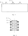
figure 3 montre, en vue développée, un mode de réalisation d'un film plastique destiné à former une nappe souple de solidarisation, - la
figure 4 montre en vue de profil un mode de réalisation d'un pré-assemblage selon l'invention, plus particulièrement adapté à une application de fixation d'un bloc isolant dans une paroi de cuve de méthanier. - la
figure 5 montre une représentation schématique écorchée d'une cuve de navire méthanier et d'un terminal de chargement/déchargement de cette cuve. - la
figure 6 est une vue schématique en perspective d'une nappe de solidarisation sous la forme d'une bande périphérique munie d'une ligne de prédécoupe. - La
figure 1 illustre un cas fréquent en assemblage mécanique. Un arbre 4, lisse ou fileté, doit accueillir une pile de pièces 2. Ces pièces sont percées d'un trou 6 apte à permettre le passage dudit arbre 4. Elles sont le plus souvent, mais pas nécessairement, de révolution autour de l'arbre 4. Les pièces 2 peuvent être des rondelles de toute sorte, des coupelles, des joints, des ressorts, etc. en fonction des besoins de l'assemblage. - Le type de chaque pièce 2, sa quantité et son ordre dans la pile, ainsi que son orientation dans le cas d'une pièce 2 non symétrique, doivent le plus souvent être respectés. Aussi dans des conditions difficiles, il peut être délicat de réaliser in situ la bonne pile et de maintenir ensemble les pièces 2 jusqu'à leur montage sur l'arbre 4.
- Aussi l'invention propose de pré-assembler les pièces 2, en atelier ou en usine, où il est possible de vérifier la pile, et de les solidariser au moyen d'une nappe souple de solidarisation 3.
- Pour cela, tel qu'illustré à la
figure 2 , il est réalisé une pile des pièces 2 nécessaires à l'assemblage, disposées en configuration de montage, soit en types, nombres et orientations conformes à la disposition finale de montage. Les pièces de cette pile sont ensuite maintenues ensemble par une nappe souple de solidarisation 3 agissant par enveloppement total ou partiel d'une surface latérale des pièces 2 de la pile. - Selon un mode de réalisation avantageux, la nappe souple de solidarisation 3 comprend un film plastique. Une épaisseur faible, caractéristique d'un film, est avantageuse en ce qu'elle ne modifie pas substantiellement les dimensions de la pile et ne modifie ainsi pas le procédé de montage.
- Le plastique utilisé ici peut être de tout type. Il est avantageusement transparent afin de permettre de contrôler les pièces 2 présentes, leur disposition et leur état.
- Selon un mode de réalisation la nappe souple de solidarisation 3 comprend une gaine thermo rétractée. Une gaine thermo rétractable permet avantageusement une réalisation aisée : la gaine est mise en place autour des pièces 2, avantageusement selon l'axe de l'arbre 4, un passage à l'air chaud réalise ensuite un rétreint de la gaine autour des pièces 2 et assure leur maintien ensemble et la tenue de la nappe souple de solidarisation 3 sur les pièces 2.
- Tout autre mode de réalisation peut encore être envisagé. Ainsi un enrobage au moyen d'un fil ou ruban peut permettre de réaliser la nappe souple de solidarisation 3 par bobinage autour de la pile.
- Alternativement ou complémentairement, la nappe souple de solidarisation peut être réalisée par un vernis ou une cire enveloppant la pile et déposé par trempage dans un bain ou encore par dépôt au pinceau ou au pistolet.
- Selon une autre caractéristique, la nappe souple de solidarisation 3 peut réaliser un enveloppement complet de la pile. Dans ce cas lors du montage l'arbre 4 perce la nappe souple de solidarisation 3 au droit du trou 6 aux deux extrémités de la pile.
- Ce perçage peut être facilité par une fragilisation de la nappe souple de solidarisation 3 au niveau des deux passages de l'arbre 4.
- Afin de faciliter le montage, selon une autre caractéristique, la nappe souple de solidarisation 3 peut encore être épargnée au niveau du passage de l'arbre 4. Selon le mode de réalisation cette épargne est initiale ou finale ; Initiale : on ne place pas ou ne dépose pas de matière lors de la réalisation de la nappe souple de solidarisation 3. Finale : la nappe souple de solidarisation 3 est réalisée intégral puis est percée de deux ouvertures 7 et 8 au droit du trou 6 aux deux extrémités de la pile.
- Selon un mode de réalisation, la nappe souple de solidarisation 3 comprend au moins une bande périphérique. Un exemple d'une telle bande périphérique est illustré à la
figure 3 . Cette bande est dite périphérique en ce qu'elle destinée à être enroulée autour de la périphérie de la pile afin de former la nappe souple de solidarisation 3. Les repères 5, triangulaires sur lafigure 3 sont, en configuration finale, tous disposés sur une surface d'extrémité de la pile, autour de l'arbre 4 une fois monté. - Selon un autre mode de réalisation, alternatif ou complémentaire, la nappe souple de solidarisation 3 comprend au moins une bande axiale. Une telle bande est dite axiale en ce qu'elle est déposée sur la pile parallèlement à l'axe de la pile et ne recouvre pas toute la surface latérale de la pile. Dans ce cas, la prédécoupe peut s'étendre sur une partie ou la totalité d'une largeur de la bande axiale.
- Selon l'invention, la nappe souple de solidarisation 3 comprend encore un adhésif pour adhérer sur les pièces 2 et/ou sur elle-même 3. L'adhésif peut ainsi permettre la tenue d'un fil ou ruban enroulé en bobine autour de la pile, tant sur la pile que sur le fil ou ruban lui-même. L'adhésif peut encore permettre la tenue d'une bande périphérique ou axiale, tant sur la pile que sur la bande elle-même. Ainsi la bande périphérique peut tenir par adhésion sur la pile et au moyen d'une sur-longueur, par adhésion sur elle-même.
- La nappe souple de solidarisation 3 peut, notamment grâce à son très faible encombrement, être laissée en place, y compris après montage. Si l'on souhaite au contraire le retirer une fois le montage réalisé, une prédécoupe est avantageusement réalisée sur la nappe souple de solidarisation 3, par exemple sous forme de pointillés, afin de faciliter un retrait de la nappe souple de solidarisation 3 après montage.
- Cette prédécoupe peut être réalisée de différentes manières. Selon un mode de réalisation particulier, illustré à la
figure 6 , la nappe souple de solidarisation 3 comprend entre les ouvertures 7 et 8 une prédécoupe 9 s'étendant sur toute la longueur d'une surface latérale de la nappe souple de solidarisation 3 en regard de la surface latérale de la pile. En variante, la prédécoupe 9 peut s'étendre seulement sur une partie de la longueur de la surface latérale de la nappe souple de solidarisation 3, depuis une des ouvertures 7 et 8. L'orientation de la prédécoupe 9 peut être axiale comme représenté ou inclinée par rapport à l'axe, par exemple en forme d'hélice. La prédécoupe 9 peut être réalisée par perforation de la nappe souple de solidarisation 3 selon un motif en pointillé. Alternativement, la prédécoupe 9 peut être réalisée par passage d'un moyen tranchant sur une partie, ou la totalité, de la longueur de la nappe souple de solidarisation 3 de sorte à fragiliser la nappe souple de solidarisation 3 au niveau de la prédécoupe. - En particulier, la nappe souple de solidarisation 3 peut comprendre une pluralité de prédécoupes similaires à la prédécoupe 9. A l'usage, la prédécoupe 9 peut être déchirée après le montage du pré-assemblage 1 sur l'arbre 4 de sorte à permettre le retrait de la nappe souple de solidarisation 1.
- Selon l'invention, illustré à la
figure 4 , la pile comprend des rondelles élastiques, aussi appelées rondelles de type Belleville. Afin d'obtenir une élasticité maximale, les rondelles Belleville sont disposées tête-bêche. Dans cette application, le nombre de rondelles est avantageusement impair. - Selon la pile réalisée, il peut arriver que le pré-assemblage ne soit pas symétrique au regard du montage sur l'arbre 4. Aussi, si les erreurs de composition de la pile sont évitées par le pré-assemblage, il convient encore d'éviter une erreur au montage où deux choix sont offerts. Pour cela, selon une autre caractéristique, il est avantageux de placer un marquage 5, visuel ou tactile, à fin de détrompage.
- Pour cela le pré-assemblage 1 est avantageusement marqué. Cette marque peut être réalisée par gravure, par dépôt de matière, par peinture ou par vernis directement sur une des pièces 2 de la pile, avantageusement une des pièces 2 extrêmes.
- Selon un mode de réalisation préférentiel en ce qu'il laisse les pièces 2 intouchées et qu'il est plus aisé à mettre en œuvre, ledit marquage 5 est réalisée par la nappe souple de solidarisation 3. Un tel marquage permet d'indiquer une orientation préférentielle du pré-assemblage 1 pour son montage sur l'arbre 4. Un tel marquage 5 peut, par exemple être une partie supplémentaire du film plastique, réalisé d'une autre couleur. Un exemple d'un tel marquage 5 est montré à la
figure 3 . La bande périphérique de forme rectangle, apte à venir s'enrouler autour de périphérie de la pile est complétée par des protubérances 5, avantageusement colorées. Après enroulement, ces protubérances 5 se retrouvent toutes autour d'un même trou 6 sur une surface d'extrémité de la pile, indiquant une orientation préférentielle du pré-assemblage 1. - L'invention concerne encore un procédé de fabrication d'un tel pré-assemblage 1 de pièces 2 aptes à être montées sur un arbre 4, telles des rondelles. Il comprend les étapes suivantes. Une première étape consiste à réaliser la pile d'au moins deux pièces. La pile correspond à la configuration de montage. Autrement dit, les pièces 2 sont disposées en types, nombres et orientations conformes aux besoins du montage mécanique. Ensuite une deuxième étape consiste à mettre en place une nappe souple de solidarisation 3 apte à solidariser lesdites au moins deux pièces 2 de la pile par enveloppement total ou partiel d'une surface latérale.
- Il est possible, selon un mode de réalisation optionnel de vérifier la pile réalisée après sa réalisation. Ceci peut par exemple se faire par mesure de la dimension de la pile, selon la direction de l'arbre 4. Cette mesure de dimension ou de hauteur de la pile peut être réalisée de différentes manières, par exemple par un système de cale, par télémétrie laser ou par un pied à coulisse. Dans un cas de réalisation selon la
figure 4 , une telle mesure permet de vérifier le bon nombre et l'orientation des pièces 2. En effet, une rondelle Belleville manquante ou mal orientée modifie grandement la hauteur de la pile. - Un tel pré-assemblage 1, comportant un empilement de rondelles Belleville, peut être utilisé dans un organe de retenue pour assembler une paroi isolante, telle qu'une paroi pour cuve de stockage d'un fluide cryogénique.
- Un organe de retenue ou coupleur réalisant l'ancrage d'un bloc isolant à une surface de support, par exemple une paroi porteuse d'un navire, est illustré à la
figure 2 de la publicationFR-A-2798902 WO-A-2017103500 . La publicationFR-A-2798902 - Dans ce cas, l'empilement de rondelles Belleville préassemblé est de préférence impair et disposé de manière que la surface d'extrémité concave soit tournée vers la platine métallique exerçant un appui sur le ou les blocs isolants et que la surface d'extrémité convexe soit tournée vers l'écrou vissé sur la tige filetée sur laquelle l'empilement est engagé.
- L'écrou peut aussi faire partie de l'empilement préassemblé.
- En référence à la
figure 5 , une vue écorchée d'un navire méthanier 70 montre une cuve étanche et isolée 71 de forme générale prismatique montée dans la double coque 72 du navire. La paroi de la cuve 71 comporte une barrière étanche primaire destinée à être en contact avec le GNL contenu dans la cuve, une barrière étanche secondaire agencée entre la barrière étanche primaire et la double coque 72 du navire, et deux barrières isolante agencées respectivement entre la barrière étanche primaire et la barrière étanche secondaire et entre la barrière étanche secondaire et la double coque 72. - De manière connue en soi, des canalisations de chargement/déchargement 73 disposées sur le pont supérieur du navire peuvent être raccordées, au moyen de connecteurs appropriées, à un terminal maritime ou portuaire pour transférer une cargaison de GNL depuis ou vers la cuve 71.
- La
figure 5 représente un exemple de terminal maritime comportant un poste de chargement et de déchargement 75, une conduite sous-marine 76 et une installation à terre 77. Le poste de chargement et de déchargement 75 est une installation fixe off-shore comportant un bras mobile 74 et une tour 78 qui supporte le bras mobile 74. Le bras mobile 74 porte un faisceau de tuyaux flexibles isolés 79 pouvant se connecter aux canalisations de chargement/déchargement 73. Le bras mobile 74 orientable s'adapte à tous les gabarits de méthaniers. Une conduite de liaison non représentée s'étend à l'intérieur de la tour 78. Le poste de chargement et de déchargement 75 permet le chargement et le déchargement du méthanier 70 depuis ou vers l'installation à terre 77. Celle-ci comporte des cuves de stockage de gaz liquéfié 80 et des conduites de liaison 81 reliées par la conduite sous-marine 76 au poste de chargement ou de déchargement 75. La conduite sous-marine 76 permet le transfert du gaz liquéfié entre le poste de chargement ou de déchargement 75 et l'installation à terre 77 sur une grande distance, par exemple 5 km, ce qui permet de garder le navire méthanier 70 à grande distance de la côte pendant les opérations de chargement et de déchargement. - Pour engendrer la pression nécessaire au transfert du gaz liquéfié, on met en œuvre des pompes embarquées dans le navire 70 et/ou des pompes équipant l'installation à terre 77 et/ou des pompes équipant le poste de chargement et de déchargement 75.
- Bien que l'invention ait été décrite en liaison avec plusieurs modes de réalisation particuliers, il est bien évident qu'elle n'y est nullement limitée et qu'elle comprend tous les équivalents techniques des moyens décrits ainsi que leurs combinaisons si celles-ci entrent dans le cadre des revendications.
- L'usage du verbe « comporter », « comprendre » ou « inclure » et de ses formes conjuguées n'exclut pas la présence d'autres éléments ou d'autres étapes que ceux énoncés dans une revendication.
- Dans les revendications, tout signe de référence entre parenthèses ne saurait être interprété comme une limitation de la revendication.
Claims (16)
- Pré-assemblage (1) de pièces (2) aptes à être montées sur un arbre (4), comprenant une pile caractérisé en ce qu'au moins deux rondelles Belleville (2) disposées en configuration de montage dans laquelle les rondelles sont disposées tête-bêche, dans lequel il comprend une nappe souple de solidarisation (3) apte à solidariser lesdites au moins deux rondelles Belleville (2) de la pile par enveloppement total ou partiel d'une surface latérale de la pile, où la nappe souple de solidarisation (3) comprend un adhésif pour adhérer sur les rondelles Belleville (2) et/ou sur elle-même (3).
- Pré-assemblage (1) selon la revendication 1, où la nappe souple de solidarisation (3) comprend un film plastique.
- Pré-assemblage (1) selon l'une quelconque des revendications 1 et 2, où la nappe souple de solidarisation (3) comprend une gaine thermo rétractée.
- Pré-assemblage (1) selon l'une quelconque des revendications 1 à 3, où la nappe souple de solidarisation (3) est épargnée ou fragilisée au niveau du passage de l'arbre (4) .
- Pré-assemblage (1) selon l'une quelconque des revendications 1 à 4, où la nappe souple de solidarisation (3) comprend au moins une bande périphérique entourant complétement la surface latérale de la pile.
- Pré-assemblage (1) selon l'une quelconque des revendications 1 à 5, où la nappe souple de solidarisation (3) comprend au moins une bande axiale s'étendant selon une direction axiale de la pile sur une portion de la surface latérale de la pile.
- Pré-assemblage (1) selon l'une quelconque des revendications 1 à 6, où la nappe souple de solidarisation (3) est prédécoupée pour faciliter son retrait après montage.
- Pré-assemblage (1) selon l'une quelconque des revendications 1 à 7, où la pile comprend des rondelles Belleville en nombre impair.
- Pré-assemblage (1) selon la revendication 8, dans lequel la pile comprend en outre un écrou.
- Pré-assemblage (1) selon l'une quelconque des revendications 1 à 9, ou le pré-assemblage (1) comprend un marquage (5), de manière à indiquer une orientation axiale de la pile.
- Paroi isolante, notamment pour cuve de stockage d'un fluide cryogénique, caractérisée en ce qu'elle comporte un organe de retenue incluant au moins un pré-assemblage (1) selon l'une quelconque des revendications 1 à 10, ledit organe de retenue mettant en prise au moins un bloc isolant pour retenir le bloc isolant sur une surface de support.
- Navire (70) pour le transport d'un fluide, le navire comportant une double coque (72) et une cuve (71) étanche et thermiquement isolante disposée dans la double coque, la cuve étanche et thermiquement isolante incluant une paroi isolante selon la revendication 11.
- Système de transfert pour un fluide, le système comportant un navire (70) selon la revendication 12, des canalisations isolées (73, 79, 76, 81) agencées de manière à relier la cuve (71) installée dans la coque du navire à une installation de stockage flottante ou terrestre (77) et une pompe pour entrainer un flux de fluide à travers les canalisations isolées depuis ou vers l'installation de stockage flottante ou terrestre vers ou depuis la cuve du navire.
- Procédé de fabrication d'un pré-assemblage (1) de pièces (2) aptes à être montées sur un arbre (4), caractérisé en ce qu'il comprend les étapes suivantes :- réalisation d'une pile comprenant au moins deux rondelles Belleville (2) disposées en configuration de montage dans laquelle les rondelles sont disposées tête-bêche,- mise en place d'une nappe souple de solidarisation (3) apte à solidariser lesdites au moins deux rondelles Belleville (2) de la pile par enveloppement total ou partiel d'une surface latérale de la pile, où la nappe souple de solidarisation (3) comprend un adhésif pour adhérer sur les rondelles Belleville (2) et/ou sur elle-même (3).
- Procédé selon la revendication 14, comprenant encore, après l'étape de réalisation, une étape de vérification de la pile réalisée, par mesure de la dimension de la pile, selon la direction de l'arbre (4).
- Procédé de chargement ou déchargement d'un navire (70) selon la revendication 12, dans lequel on achemine un fluide à travers des canalisations isolées (73, 79, 76, 81) depuis ou vers une installation de stockage flottante ou terrestre (77) vers ou depuis la cuve (71) du navire (70) selon la revendication 12.
Applications Claiming Priority (2)
| Application Number | Priority Date | Filing Date | Title |
|---|---|---|---|
| FR1852826A FR3079436B1 (fr) | 2018-03-30 | 2018-03-30 | Pre-assemblage de pieces |
| PCT/FR2019/050747 WO2019186083A1 (fr) | 2018-03-30 | 2019-03-29 | Pré-assemblage de pièces |
Publications (2)
| Publication Number | Publication Date |
|---|---|
| EP3774186A1 EP3774186A1 (fr) | 2021-02-17 |
| EP3774186B1 true EP3774186B1 (fr) | 2022-06-01 |
Family
ID=62816728
Family Applications (1)
| Application Number | Title | Priority Date | Filing Date |
|---|---|---|---|
| EP19719350.1A Active EP3774186B1 (fr) | 2018-03-30 | 2019-03-29 | Pré-assemblage de pièces |
Country Status (7)
| Country | Link |
|---|---|
| EP (1) | EP3774186B1 (fr) |
| KR (1) | KR102613004B1 (fr) |
| CN (1) | CN112135712B (fr) |
| ES (1) | ES2924377T3 (fr) |
| FR (1) | FR3079436B1 (fr) |
| SG (1) | SG11202009656UA (fr) |
| WO (1) | WO2019186083A1 (fr) |
Family Cites Families (12)
| Publication number | Priority date | Publication date | Assignee | Title |
|---|---|---|---|---|
| FR2088813A5 (fr) * | 1970-04-24 | 1972-01-07 | Pont A Mousson | |
| FR2639560B1 (fr) * | 1988-11-29 | 1994-04-08 | Application Machines Motrices | Procede et dispositif pour le sertissage par magnetoformage de patins sur des tetes de pistons de pompes hydrauliques |
| JP2000255672A (ja) * | 1999-03-02 | 2000-09-19 | Taiyo Yuden Co Ltd | 光ディスクの収納体 |
| FR2798902B1 (fr) * | 1999-09-29 | 2001-11-23 | Gaz Transport & Technigaz | Cuve etanche et thermiquement isolante integree dans une structure porteuse de navire et procede de fabrication de caissons isolants destines a etre utilises dans cette cuve |
| FR2898590B1 (fr) * | 2006-03-16 | 2008-05-09 | Manuf Generale De Joints Soc P | Emballage pour joints |
| FR2903333B1 (fr) * | 2006-07-06 | 2010-01-01 | Erad Frabce | Procede de montage d'un soufflet de cardan, ensemble de montage comprenant un soufflet de cardan et utilisation d'un accessoire pour monter un soufflet de cardan |
| US8703265B2 (en) * | 2007-03-23 | 2014-04-22 | Selig Sealing Products, Inc. | Container seal with removal tab and piercable holographic security seal |
| JP2011048065A (ja) * | 2009-08-26 | 2011-03-10 | Nippon Zeon Co Ltd | 延伸フィルム |
| FR3004511B1 (fr) * | 2013-04-15 | 2016-12-30 | Gaztransport Et Technigaz | Cuve etanche et thermiquement isolante |
| FR3008684B1 (fr) * | 2013-07-16 | 2015-08-21 | Smurfit Kappa France | Emballage comprenant un element en materiau semi rigide et un film thermoretractable. |
| FR3026459B1 (fr) * | 2014-09-26 | 2017-06-09 | Gaztransport Et Technigaz | Cuve etanche et isolante comportant un element de pontage entre les panneaux de la barriere isolante secondaire |
| FR3030014B1 (fr) * | 2014-12-15 | 2017-10-13 | Gaztransport Et Technigaz | Bloc isolant convenant pour realiser une paroi isolante dans une cuve etanche |
-
2018
- 2018-03-30 FR FR1852826A patent/FR3079436B1/fr not_active Expired - Fee Related
-
2019
- 2019-03-29 ES ES19719350T patent/ES2924377T3/es active Active
- 2019-03-29 CN CN201980033419.8A patent/CN112135712B/zh active Active
- 2019-03-29 EP EP19719350.1A patent/EP3774186B1/fr active Active
- 2019-03-29 KR KR1020207028344A patent/KR102613004B1/ko active Active
- 2019-03-29 SG SG11202009656UA patent/SG11202009656UA/en unknown
- 2019-03-29 WO PCT/FR2019/050747 patent/WO2019186083A1/fr not_active Ceased
Also Published As
| Publication number | Publication date |
|---|---|
| RU2020131587A (ru) | 2022-05-04 |
| FR3079436A1 (fr) | 2019-10-04 |
| ES2924377T3 (es) | 2022-10-06 |
| KR20200138745A (ko) | 2020-12-10 |
| RU2020131587A3 (fr) | 2022-05-04 |
| SG11202009656UA (en) | 2020-10-29 |
| FR3079436B1 (fr) | 2021-02-12 |
| CN112135712A (zh) | 2020-12-25 |
| KR102613004B1 (ko) | 2023-12-12 |
| WO2019186083A1 (fr) | 2019-10-03 |
| EP3774186A1 (fr) | 2021-02-17 |
| CN112135712B (zh) | 2023-08-04 |
Similar Documents
| Publication | Publication Date | Title |
|---|---|---|
| EP3365592B1 (fr) | Cuve comprenant des blocs isolants de coin equipes de fentes de relaxation | |
| EP2986886B1 (fr) | Cuve étanche et thermiquement isolante | |
| FR3001945A1 (fr) | Paroi etanche et thermiquement isolante pour cuve de stockage de fluide | |
| FR3073270B1 (fr) | Cuve etanche et thermiquement isolante comportant des dispositifs d'ancrage des panneaux isolants primaires sur des panneaux isolants secondaires | |
| FR3112588A1 (fr) | Paroi d'une cuve de stockage d'un gaz liquéfiée | |
| EP4013989B1 (fr) | Cuve étanche et thermiquement isolante | |
| EP3645933B1 (fr) | Membrane etanche et procede d'assemblage d'une membrane etanche | |
| FR3069903B1 (fr) | Cuve etanche et themiquement isolante | |
| WO2019186083A1 (fr) | Pré-assemblage de pièces | |
| WO2021255000A1 (fr) | Dôme liquide d'une cuve de stockage pour gaz liquéfié | |
| EP4222406B1 (fr) | Procédé d'assemblage et installation de cuve de stockage pour gaz liquéfié | |
| WO2021254999A1 (fr) | Dôme liquide d'une cuve de stockage pour gaz liquéfié | |
| RU2794188C2 (ru) | Предварительно собранный узел деталей | |
| WO2025186270A1 (fr) | Structure d'angle pour cuve etanche et thermiquement isolante et cuve comportant une telle structure d'angle | |
| WO2026041449A1 (fr) | Cuve étanche et thermiquement isolante et procédé de fabrication d'une telle cuve | |
| WO2026041440A1 (fr) | Pièce de jonction, paroi de cuve comportant une telle pièce de jonction et procédé de fabrication d'une telle paroi | |
| WO2023186866A1 (fr) | Cuve étanche et thermiquement isolante | |
| EP4477939A1 (fr) | Cuve de réservoir comprenant une virole et au moins une paroi d' extrémité assemblées de manière à limiter les déformations de ladite paroi d' extrémité | |
| EP4596953A1 (fr) | Installation de stockage d'un gaz liquéfié | |
| WO2024003482A1 (fr) | Procédé d'assemblage d'un système anti-ballotement dans une cuve de stockage | |
| FR3141746A1 (fr) | Cuve étanche et thermiquement isolante | |
| FR3162495A1 (fr) | Cuve étanche et thermiquement isolante équipée d’une tour de chargement/déchargement | |
| WO2021249952A1 (fr) | Bloc isolant convenant pour le soutien et l'isolation thermique d'une membrane étanche destinée à contenir un fluide | |
| FR3109544A1 (fr) | Procédé de fabrication d’un fût de dôme d’une cuve étanche et thermiquement isolante | |
| FR3102532A1 (fr) | Cuve de gaz naturel à l’état liquide d’un navire |
Legal Events
| Date | Code | Title | Description |
|---|---|---|---|
| STAA | Information on the status of an ep patent application or granted ep patent |
Free format text: STATUS: UNKNOWN |
|
| STAA | Information on the status of an ep patent application or granted ep patent |
Free format text: STATUS: THE INTERNATIONAL PUBLICATION HAS BEEN MADE |
|
| PUAI | Public reference made under article 153(3) epc to a published international application that has entered the european phase |
Free format text: ORIGINAL CODE: 0009012 |
|
| STAA | Information on the status of an ep patent application or granted ep patent |
Free format text: STATUS: REQUEST FOR EXAMINATION WAS MADE |
|
| 17P | Request for examination filed |
Effective date: 20201027 |
|
| AK | Designated contracting states |
Kind code of ref document: A1 Designated state(s): AL AT BE BG CH CY CZ DE DK EE ES FI FR GB GR HR HU IE IS IT LI LT LU LV MC MK MT NL NO PL PT RO RS SE SI SK SM TR |
|
| AX | Request for extension of the european patent |
Extension state: BA ME |
|
| DAV | Request for validation of the european patent (deleted) | ||
| DAX | Request for extension of the european patent (deleted) | ||
| REG | Reference to a national code |
Ref country code: DE Ref legal event code: R079 Ref document number: 602019015424 Country of ref document: DE Free format text: PREVIOUS MAIN CLASS: B25B0027140000 Ipc: B25B0027000000 |
|
| RIC1 | Information provided on ipc code assigned before grant |
Ipc: F17C 3/00 20060101ALN20211111BHEP Ipc: B63B 25/16 20060101ALN20211111BHEP Ipc: B23P 19/08 20060101ALN20211111BHEP Ipc: F17C 13/00 20060101ALI20211111BHEP Ipc: B25B 27/14 20060101ALI20211111BHEP Ipc: B25B 27/00 20060101AFI20211111BHEP |
|
| GRAP | Despatch of communication of intention to grant a patent |
Free format text: ORIGINAL CODE: EPIDOSNIGR1 |
|
| STAA | Information on the status of an ep patent application or granted ep patent |
Free format text: STATUS: GRANT OF PATENT IS INTENDED |
|
| INTG | Intention to grant announced |
Effective date: 20220105 |
|
| GRAS | Grant fee paid |
Free format text: ORIGINAL CODE: EPIDOSNIGR3 |
|
| GRAA | (expected) grant |
Free format text: ORIGINAL CODE: 0009210 |
|
| STAA | Information on the status of an ep patent application or granted ep patent |
Free format text: STATUS: THE PATENT HAS BEEN GRANTED |
|
| AK | Designated contracting states |
Kind code of ref document: B1 Designated state(s): AL AT BE BG CH CY CZ DE DK EE ES FI FR GB GR HR HU IE IS IT LI LT LU LV MC MK MT NL NO PL PT RO RS SE SI SK SM TR |
|
| REG | Reference to a national code |
Ref country code: GB Ref legal event code: FG4D Free format text: NOT ENGLISH |
|
| REG | Reference to a national code |
Ref country code: AT Ref legal event code: REF Ref document number: 1495048 Country of ref document: AT Kind code of ref document: T Effective date: 20220615 Ref country code: CH Ref legal event code: EP |
|
| REG | Reference to a national code |
Ref country code: IE Ref legal event code: FG4D Free format text: LANGUAGE OF EP DOCUMENT: FRENCH |
|
| REG | Reference to a national code |
Ref country code: DE Ref legal event code: R096 Ref document number: 602019015424 Country of ref document: DE |
|
| REG | Reference to a national code |
Ref country code: NO Ref legal event code: T2 Effective date: 20220601 |
|
| REG | Reference to a national code |
Ref country code: LT Ref legal event code: MG9D |
|
| REG | Reference to a national code |
Ref country code: NL Ref legal event code: MP Effective date: 20220601 |
|
| REG | Reference to a national code |
Ref country code: ES Ref legal event code: FG2A Ref document number: 2924377 Country of ref document: ES Kind code of ref document: T3 Effective date: 20221006 |
|
| PG25 | Lapsed in a contracting state [announced via postgrant information from national office to epo] |
Ref country code: SE Free format text: LAPSE BECAUSE OF FAILURE TO SUBMIT A TRANSLATION OF THE DESCRIPTION OR TO PAY THE FEE WITHIN THE PRESCRIBED TIME-LIMIT Effective date: 20220601 Ref country code: LT Free format text: LAPSE BECAUSE OF FAILURE TO SUBMIT A TRANSLATION OF THE DESCRIPTION OR TO PAY THE FEE WITHIN THE PRESCRIBED TIME-LIMIT Effective date: 20220601 Ref country code: HR Free format text: LAPSE BECAUSE OF FAILURE TO SUBMIT A TRANSLATION OF THE DESCRIPTION OR TO PAY THE FEE WITHIN THE PRESCRIBED TIME-LIMIT Effective date: 20220601 Ref country code: GR Free format text: LAPSE BECAUSE OF FAILURE TO SUBMIT A TRANSLATION OF THE DESCRIPTION OR TO PAY THE FEE WITHIN THE PRESCRIBED TIME-LIMIT Effective date: 20220902 Ref country code: FI Free format text: LAPSE BECAUSE OF FAILURE TO SUBMIT A TRANSLATION OF THE DESCRIPTION OR TO PAY THE FEE WITHIN THE PRESCRIBED TIME-LIMIT Effective date: 20220601 Ref country code: BG Free format text: LAPSE BECAUSE OF FAILURE TO SUBMIT A TRANSLATION OF THE DESCRIPTION OR TO PAY THE FEE WITHIN THE PRESCRIBED TIME-LIMIT Effective date: 20220901 |
|
| REG | Reference to a national code |
Ref country code: AT Ref legal event code: MK05 Ref document number: 1495048 Country of ref document: AT Kind code of ref document: T Effective date: 20220601 |
|
| PG25 | Lapsed in a contracting state [announced via postgrant information from national office to epo] |
Ref country code: RS Free format text: LAPSE BECAUSE OF FAILURE TO SUBMIT A TRANSLATION OF THE DESCRIPTION OR TO PAY THE FEE WITHIN THE PRESCRIBED TIME-LIMIT Effective date: 20220601 Ref country code: PL Free format text: LAPSE BECAUSE OF FAILURE TO SUBMIT A TRANSLATION OF THE DESCRIPTION OR TO PAY THE FEE WITHIN THE PRESCRIBED TIME-LIMIT Effective date: 20220601 Ref country code: LV Free format text: LAPSE BECAUSE OF FAILURE TO SUBMIT A TRANSLATION OF THE DESCRIPTION OR TO PAY THE FEE WITHIN THE PRESCRIBED TIME-LIMIT Effective date: 20220601 |
|
| PG25 | Lapsed in a contracting state [announced via postgrant information from national office to epo] |
Ref country code: NL Free format text: LAPSE BECAUSE OF FAILURE TO SUBMIT A TRANSLATION OF THE DESCRIPTION OR TO PAY THE FEE WITHIN THE PRESCRIBED TIME-LIMIT Effective date: 20220601 |
|
| PG25 | Lapsed in a contracting state [announced via postgrant information from national office to epo] |
Ref country code: SM Free format text: LAPSE BECAUSE OF FAILURE TO SUBMIT A TRANSLATION OF THE DESCRIPTION OR TO PAY THE FEE WITHIN THE PRESCRIBED TIME-LIMIT Effective date: 20220601 Ref country code: SK Free format text: LAPSE BECAUSE OF FAILURE TO SUBMIT A TRANSLATION OF THE DESCRIPTION OR TO PAY THE FEE WITHIN THE PRESCRIBED TIME-LIMIT Effective date: 20220601 Ref country code: RO Free format text: LAPSE BECAUSE OF FAILURE TO SUBMIT A TRANSLATION OF THE DESCRIPTION OR TO PAY THE FEE WITHIN THE PRESCRIBED TIME-LIMIT Effective date: 20220601 Ref country code: PT Free format text: LAPSE BECAUSE OF FAILURE TO SUBMIT A TRANSLATION OF THE DESCRIPTION OR TO PAY THE FEE WITHIN THE PRESCRIBED TIME-LIMIT Effective date: 20221003 Ref country code: EE Free format text: LAPSE BECAUSE OF FAILURE TO SUBMIT A TRANSLATION OF THE DESCRIPTION OR TO PAY THE FEE WITHIN THE PRESCRIBED TIME-LIMIT Effective date: 20220601 Ref country code: CZ Free format text: LAPSE BECAUSE OF FAILURE TO SUBMIT A TRANSLATION OF THE DESCRIPTION OR TO PAY THE FEE WITHIN THE PRESCRIBED TIME-LIMIT Effective date: 20220601 Ref country code: AT Free format text: LAPSE BECAUSE OF FAILURE TO SUBMIT A TRANSLATION OF THE DESCRIPTION OR TO PAY THE FEE WITHIN THE PRESCRIBED TIME-LIMIT Effective date: 20220601 |
|
| PG25 | Lapsed in a contracting state [announced via postgrant information from national office to epo] |
Ref country code: IS Free format text: LAPSE BECAUSE OF FAILURE TO SUBMIT A TRANSLATION OF THE DESCRIPTION OR TO PAY THE FEE WITHIN THE PRESCRIBED TIME-LIMIT Effective date: 20221001 |
|
| REG | Reference to a national code |
Ref country code: DE Ref legal event code: R097 Ref document number: 602019015424 Country of ref document: DE |
|
| PG25 | Lapsed in a contracting state [announced via postgrant information from national office to epo] |
Ref country code: AL Free format text: LAPSE BECAUSE OF FAILURE TO SUBMIT A TRANSLATION OF THE DESCRIPTION OR TO PAY THE FEE WITHIN THE PRESCRIBED TIME-LIMIT Effective date: 20220601 |
|
| PLBE | No opposition filed within time limit |
Free format text: ORIGINAL CODE: 0009261 |
|
| STAA | Information on the status of an ep patent application or granted ep patent |
Free format text: STATUS: NO OPPOSITION FILED WITHIN TIME LIMIT |
|
| PG25 | Lapsed in a contracting state [announced via postgrant information from national office to epo] |
Ref country code: DK Free format text: LAPSE BECAUSE OF FAILURE TO SUBMIT A TRANSLATION OF THE DESCRIPTION OR TO PAY THE FEE WITHIN THE PRESCRIBED TIME-LIMIT Effective date: 20220601 |
|
| 26N | No opposition filed |
Effective date: 20230302 |
|
| PG25 | Lapsed in a contracting state [announced via postgrant information from national office to epo] |
Ref country code: SI Free format text: LAPSE BECAUSE OF FAILURE TO SUBMIT A TRANSLATION OF THE DESCRIPTION OR TO PAY THE FEE WITHIN THE PRESCRIBED TIME-LIMIT Effective date: 20220601 |
|
| P01 | Opt-out of the competence of the unified patent court (upc) registered |
Effective date: 20230614 |
|
| PG25 | Lapsed in a contracting state [announced via postgrant information from national office to epo] |
Ref country code: MC Free format text: LAPSE BECAUSE OF FAILURE TO SUBMIT A TRANSLATION OF THE DESCRIPTION OR TO PAY THE FEE WITHIN THE PRESCRIBED TIME-LIMIT Effective date: 20220601 |
|
| REG | Reference to a national code |
Ref country code: CH Ref legal event code: PL |
|
| GBPC | Gb: european patent ceased through non-payment of renewal fee |
Effective date: 20230329 |
|
| REG | Reference to a national code |
Ref country code: BE Ref legal event code: MM Effective date: 20230331 |
|
| PG25 | Lapsed in a contracting state [announced via postgrant information from national office to epo] |
Ref country code: LU Free format text: LAPSE BECAUSE OF NON-PAYMENT OF DUE FEES Effective date: 20230329 |
|
| REG | Reference to a national code |
Ref country code: IE Ref legal event code: MM4A |
|
| PG25 | Lapsed in a contracting state [announced via postgrant information from national office to epo] |
Ref country code: GB Free format text: LAPSE BECAUSE OF NON-PAYMENT OF DUE FEES Effective date: 20230329 |
|
| PG25 | Lapsed in a contracting state [announced via postgrant information from national office to epo] |
Ref country code: LI Free format text: LAPSE BECAUSE OF NON-PAYMENT OF DUE FEES Effective date: 20230331 Ref country code: IT Free format text: LAPSE BECAUSE OF FAILURE TO SUBMIT A TRANSLATION OF THE DESCRIPTION OR TO PAY THE FEE WITHIN THE PRESCRIBED TIME-LIMIT Effective date: 20220601 Ref country code: IE Free format text: LAPSE BECAUSE OF NON-PAYMENT OF DUE FEES Effective date: 20230329 Ref country code: GB Free format text: LAPSE BECAUSE OF NON-PAYMENT OF DUE FEES Effective date: 20230329 Ref country code: CH Free format text: LAPSE BECAUSE OF NON-PAYMENT OF DUE FEES Effective date: 20230331 |
|
| PG25 | Lapsed in a contracting state [announced via postgrant information from national office to epo] |
Ref country code: BE Free format text: LAPSE BECAUSE OF NON-PAYMENT OF DUE FEES Effective date: 20230331 |
|
| PG25 | Lapsed in a contracting state [announced via postgrant information from national office to epo] |
Ref country code: BG Free format text: LAPSE BECAUSE OF FAILURE TO SUBMIT A TRANSLATION OF THE DESCRIPTION OR TO PAY THE FEE WITHIN THE PRESCRIBED TIME-LIMIT Effective date: 20220601 |
|
| PG25 | Lapsed in a contracting state [announced via postgrant information from national office to epo] |
Ref country code: BG Free format text: LAPSE BECAUSE OF FAILURE TO SUBMIT A TRANSLATION OF THE DESCRIPTION OR TO PAY THE FEE WITHIN THE PRESCRIBED TIME-LIMIT Effective date: 20220601 |
|
| PGFP | Annual fee paid to national office [announced via postgrant information from national office to epo] |
Ref country code: ES Payment date: 20250410 Year of fee payment: 7 |
|
| PG25 | Lapsed in a contracting state [announced via postgrant information from national office to epo] |
Ref country code: CY Free format text: LAPSE BECAUSE OF FAILURE TO SUBMIT A TRANSLATION OF THE DESCRIPTION OR TO PAY THE FEE WITHIN THE PRESCRIBED TIME-LIMIT; INVALID AB INITIO Effective date: 20190329 |
|
| PG25 | Lapsed in a contracting state [announced via postgrant information from national office to epo] |
Ref country code: HU Free format text: LAPSE BECAUSE OF FAILURE TO SUBMIT A TRANSLATION OF THE DESCRIPTION OR TO PAY THE FEE WITHIN THE PRESCRIBED TIME-LIMIT; INVALID AB INITIO Effective date: 20190329 |
|
| PG25 | Lapsed in a contracting state [announced via postgrant information from national office to epo] |
Ref country code: TR Free format text: LAPSE BECAUSE OF FAILURE TO SUBMIT A TRANSLATION OF THE DESCRIPTION OR TO PAY THE FEE WITHIN THE PRESCRIBED TIME-LIMIT Effective date: 20220601 |
|
| PGFP | Annual fee paid to national office [announced via postgrant information from national office to epo] |
Ref country code: NO Payment date: 20260226 Year of fee payment: 8 Ref country code: DE Payment date: 20260313 Year of fee payment: 8 |
|
| PGFP | Annual fee paid to national office [announced via postgrant information from national office to epo] |
Ref country code: FR Payment date: 20260330 Year of fee payment: 8 |