EP3772643A1 - Appareil et procédé de mesure de matière particulaire - Google Patents
Appareil et procédé de mesure de matière particulaire Download PDFInfo
- Publication number
- EP3772643A1 EP3772643A1 EP20174912.4A EP20174912A EP3772643A1 EP 3772643 A1 EP3772643 A1 EP 3772643A1 EP 20174912 A EP20174912 A EP 20174912A EP 3772643 A1 EP3772643 A1 EP 3772643A1
- Authority
- EP
- European Patent Office
- Prior art keywords
- particulate matter
- matter particles
- light
- particles
- image
- Prior art date
- Legal status (The legal status is an assumption and is not a legal conclusion. Google has not performed a legal analysis and makes no representation as to the accuracy of the status listed.)
- Granted
Links
Images


Classifications
-
- G—PHYSICS
- G01—MEASURING; TESTING
- G01N—INVESTIGATING OR ANALYSING MATERIALS BY DETERMINING THEIR CHEMICAL OR PHYSICAL PROPERTIES
- G01N15/00—Investigating characteristics of particles; Investigating permeability, pore-volume or surface-area of porous materials
- G01N15/06—Investigating concentration of particle suspensions
- G01N15/0606—Investigating concentration of particle suspensions by collecting particles on a support
- G01N15/0618—Investigating concentration of particle suspensions by collecting particles on a support of the filter type
-
- G—PHYSICS
- G01—MEASURING; TESTING
- G01J—MEASUREMENT OF INTENSITY, VELOCITY, SPECTRAL CONTENT, POLARISATION, PHASE OR PULSE CHARACTERISTICS OF INFRARED, VISIBLE OR ULTRAVIOLET LIGHT; COLORIMETRY; RADIATION PYROMETRY
- G01J3/00—Spectrometry; Spectrophotometry; Monochromators; Measuring colours
- G01J3/28—Investigating the spectrum
- G01J3/44—Raman spectrometry; Scattering spectrometry ; Fluorescence spectrometry
-
- G—PHYSICS
- G01—MEASURING; TESTING
- G01N—INVESTIGATING OR ANALYSING MATERIALS BY DETERMINING THEIR CHEMICAL OR PHYSICAL PROPERTIES
- G01N15/00—Investigating characteristics of particles; Investigating permeability, pore-volume or surface-area of porous materials
- G01N15/02—Investigating particle size or size distribution
- G01N15/0205—Investigating particle size or size distribution by optical means
- G01N15/0211—Investigating a scatter or diffraction pattern
-
- G—PHYSICS
- G01—MEASURING; TESTING
- G01N—INVESTIGATING OR ANALYSING MATERIALS BY DETERMINING THEIR CHEMICAL OR PHYSICAL PROPERTIES
- G01N15/00—Investigating characteristics of particles; Investigating permeability, pore-volume or surface-area of porous materials
- G01N15/02—Investigating particle size or size distribution
- G01N15/0205—Investigating particle size or size distribution by optical means
- G01N15/0227—Investigating particle size or size distribution by optical means using imaging; using holography
-
- G—PHYSICS
- G01—MEASURING; TESTING
- G01N—INVESTIGATING OR ANALYSING MATERIALS BY DETERMINING THEIR CHEMICAL OR PHYSICAL PROPERTIES
- G01N15/00—Investigating characteristics of particles; Investigating permeability, pore-volume or surface-area of porous materials
- G01N15/06—Investigating concentration of particle suspensions
- G01N15/0606—Investigating concentration of particle suspensions by collecting particles on a support
-
- G—PHYSICS
- G01—MEASURING; TESTING
- G01N—INVESTIGATING OR ANALYSING MATERIALS BY DETERMINING THEIR CHEMICAL OR PHYSICAL PROPERTIES
- G01N15/00—Investigating characteristics of particles; Investigating permeability, pore-volume or surface-area of porous materials
- G01N15/06—Investigating concentration of particle suspensions
- G01N15/0656—Investigating concentration of particle suspensions using electric, e.g. electrostatic methods or magnetic methods
-
- G—PHYSICS
- G01—MEASURING; TESTING
- G01N—INVESTIGATING OR ANALYSING MATERIALS BY DETERMINING THEIR CHEMICAL OR PHYSICAL PROPERTIES
- G01N15/00—Investigating characteristics of particles; Investigating permeability, pore-volume or surface-area of porous materials
- G01N15/10—Investigating individual particles
- G01N15/14—Optical investigation techniques, e.g. flow cytometry
- G01N15/1434—Optical arrangements
-
- G—PHYSICS
- G01—MEASURING; TESTING
- G01N—INVESTIGATING OR ANALYSING MATERIALS BY DETERMINING THEIR CHEMICAL OR PHYSICAL PROPERTIES
- G01N21/00—Investigating or analysing materials by the use of optical means, i.e. using sub-millimetre waves, infrared, visible or ultraviolet light
- G01N21/62—Systems in which the material investigated is excited whereby it emits light or causes a change in wavelength of the incident light
- G01N21/63—Systems in which the material investigated is excited whereby it emits light or causes a change in wavelength of the incident light optically excited
- G01N21/65—Raman scattering
-
- G—PHYSICS
- G01—MEASURING; TESTING
- G01N—INVESTIGATING OR ANALYSING MATERIALS BY DETERMINING THEIR CHEMICAL OR PHYSICAL PROPERTIES
- G01N15/00—Investigating characteristics of particles; Investigating permeability, pore-volume or surface-area of porous materials
- G01N15/06—Investigating concentration of particle suspensions
- G01N15/075—Investigating concentration of particle suspensions by optical means
-
- G—PHYSICS
- G01—MEASURING; TESTING
- G01N—INVESTIGATING OR ANALYSING MATERIALS BY DETERMINING THEIR CHEMICAL OR PHYSICAL PROPERTIES
- G01N15/00—Investigating characteristics of particles; Investigating permeability, pore-volume or surface-area of porous materials
- G01N2015/0023—Investigating dispersion of liquids
- G01N2015/0026—Investigating dispersion of liquids in gas, e.g. fog
-
- G—PHYSICS
- G01—MEASURING; TESTING
- G01N—INVESTIGATING OR ANALYSING MATERIALS BY DETERMINING THEIR CHEMICAL OR PHYSICAL PROPERTIES
- G01N15/00—Investigating characteristics of particles; Investigating permeability, pore-volume or surface-area of porous materials
- G01N2015/0042—Investigating dispersion of solids
- G01N2015/0046—Investigating dispersion of solids in gas, e.g. smoke
-
- G—PHYSICS
- G01—MEASURING; TESTING
- G01N—INVESTIGATING OR ANALYSING MATERIALS BY DETERMINING THEIR CHEMICAL OR PHYSICAL PROPERTIES
- G01N15/00—Investigating characteristics of particles; Investigating permeability, pore-volume or surface-area of porous materials
- G01N15/10—Investigating individual particles
- G01N15/14—Optical investigation techniques, e.g. flow cytometry
- G01N15/1434—Optical arrangements
- G01N2015/144—Imaging characterised by its optical setup
-
- G—PHYSICS
- G01—MEASURING; TESTING
- G01N—INVESTIGATING OR ANALYSING MATERIALS BY DETERMINING THEIR CHEMICAL OR PHYSICAL PROPERTIES
- G01N21/00—Investigating or analysing materials by the use of optical means, i.e. using sub-millimetre waves, infrared, visible or ultraviolet light
- G01N21/01—Arrangements or apparatus for facilitating the optical investigation
- G01N21/03—Cuvette constructions
- G01N21/031—Multipass arrangements
-
- G—PHYSICS
- G01—MEASURING; TESTING
- G01N—INVESTIGATING OR ANALYSING MATERIALS BY DETERMINING THEIR CHEMICAL OR PHYSICAL PROPERTIES
- G01N2201/00—Features of devices classified in G01N21/00
- G01N2201/06—Illumination; Optics
- G01N2201/061—Sources
- G01N2201/06113—Coherent sources; lasers
- G01N2201/0612—Laser diodes
-
- G—PHYSICS
- G01—MEASURING; TESTING
- G01N—INVESTIGATING OR ANALYSING MATERIALS BY DETERMINING THEIR CHEMICAL OR PHYSICAL PROPERTIES
- G01N2201/00—Features of devices classified in G01N21/00
- G01N2201/06—Illumination; Optics
- G01N2201/062—LED's
-
- G—PHYSICS
- G01—MEASURING; TESTING
- G01N—INVESTIGATING OR ANALYSING MATERIALS BY DETERMINING THEIR CHEMICAL OR PHYSICAL PROPERTIES
- G01N2201/00—Features of devices classified in G01N21/00
- G01N2201/08—Optical fibres; light guides
Definitions
- Example embodiments of the present disclosure relate to technology for measuring particulate matter.
- Particulate matter may include very small particles and liquid droplets suspended in the air, which are so small such that they are not visible to the eye, including particles having a diameter of 10 ⁇ m or less.
- Such particulate matter may be emitted from combustion of fossil fuels, such as coal, oil, and the like, or exhaust gases from cars, factories, and the like.
- particulate matter has become a serious threat to both human health and the environment.
- Long-time exposure to particulate matter can lead to a significant decrease in the level of immunity, causing various health problems including respiratory diseases, such as cold, asthma, bronchitis, and the like, as well as cardiovascular diseases, skin diseases, eye problems, and the like.
- respiratory diseases such as cold, asthma, bronchitis, and the like
- cardiovascular diseases such as skin diseases, eye problems, and the like.
- fine particulate matter having a diameter of 2.5 ⁇ m or less tends to penetrate deep into the lungs and the bronchial tubes in the body, and sticks to the lungs and the bronchial tubes which may cause various diseases.
- One or more example embodiments provide an apparatus and method for measuring the size, concentration, and components of particulate matter particles at the same time.
- an apparatus for measuring particulate matter including an image obtaining device configured to charge particulate matter particles included in air that is introduced to the image obtaining device, and to obtain an image of the charged particulate matter particles based on lens-free imaging, a spectrum obtaining device configured to obtain a Raman spectrum of the charged particulate matter particles, and a processor configured to determine a size of the particulate matter particles and a concentration of the particulate matter particles based on the obtained image, and to determine components of the particulate matter particles based on the obtained Raman spectrum.
- lens-free imaging generally refers to imaging without a lens, in particular, on-chip lens-free imaging, more particularly, involving computational imaging.
- the image obtaining device may include a particulate matter adsorbing device configured to charge the particulate matter particles and to adsorb the charged particulate matter particles, a light source configured to emit light to the adsorbed particulate matter particles, and an image generating device configured to generate an image of the particulate matter particles by receiving light having passed through the adsorbed particulate matter particles, light reflected from the adsorbed particulate matter particles, or light scattered from the adsorbed particulate matter particles.
- the particulate matter adsorbing device may include a first electrode to which one of a positive polarity or a negative polarity is applied and configured to charge the particulate matter particles, and a second electrode to which the other one of the positive polarity and the negative polarity is applied and configured to adsorb the charged particulate matter particles.
- the second electrode may have a plate shape.
- the second electrode may be formed of one of indium tin oxide (ITO), indium zinc oxide (IZO), SnO2, zinc oxide (ZnO), graphene, silver nanowire, conductive polymer (e.g., PEDOT:PSS), and carbon nanotube.
- ITO indium tin oxide
- IZO indium zinc oxide
- SnO2 zinc oxide
- ZnO zinc oxide
- graphene silver nanowire
- conductive polymer e.g., PEDOT:PSS
- carbon nanotube carbon nanotube
- the image generating device may include at least one of a charge-coupled device (CCD) and a complementary metal oxide semiconductor (CMOS).
- CCD charge-coupled device
- CMOS complementary metal oxide semiconductor
- the spectrum obtaining device may include a waveguide into which the charged particulate matter particles are introduced, a light source configured to emit light to the charged particulate matter particles introduced into the waveguide, and a spectrum generating device configured to generate the Raman spectrum of the charged particulate matter particles by receiving Raman scattered light of the charged particulate matter particles introduced into the waveguide.
- the waveguide may be configured to discharge the charged particulate matter particles to an outside of the apparatus for measuring particulate matter.
- the light source may be disposed proximate to an inlet of the waveguide, and the spectrum generating device is disposed proximate to an outlet of the waveguide.
- the spectrum generating device may include a spectrometer configured to separate the Raman scattered light into light of different wavelengths, and a generating device configured to obtain the Raman spectrum by receiving the Raman scattered light which is separated into the light of different wavelengths.
- the spectrometer may include at least one of a prism, a grating, and a filter.
- the generating device may include at least one of a charge-coupled device (CCD) and a complementary metal oxide semiconductor (CMOS).
- CCD charge-coupled device
- CMOS complementary metal oxide semiconductor
- a method of measuring particulate matter including charging particulate matter particles included in air, obtaining an image of the charged particulate matter particles based on lens-free imaging, obtaining a Raman spectrum of the charged particulate matter particles, determining a size of the particulate matter particles and a concentration of the particulate matter particles based on the obtained image, and determining components of the particulate matter particles based on the obtained Raman spectrum.
- the obtaining of the image may include adsorbing the charged particulate matter particles, emitting light to the adsorbed particulate matter particles, and generating an image of the particulate matter particles by receiving light having passed through the adsorbed particulate matter particles, light reflected from the adsorbed particulate matter particles, or light scattered from the adsorbed particulate matter particles.
- the Raman spectrum may include emitting light to the charged particulate matter particles introduced into the waveguide, and generating a Raman spectrum of the charged particulate matter particles by receiving Raman scattered light of the charged particulate matter particles introduced into the waveguide.
- an apparatus for measuring particulate matter including an image obtaining device configured to charge particulate matter particles included in air that is introduced to the image obtaining device, and to obtain an image of the charged particulate matter particles based on lens-free imaging, a waveguide into which the charged particulate matter particles are introduced, a spectrum obtaining device configured to obtain a Raman spectrum of the charged particulate matter particles by receiving the Raman scattered light of the charged particulate matter particles introduced into the waveguide, and a processor configured to determine a size of the particulate matter particles and a concentration of the particulate matter particles based on the obtained image, and to determine components of the particulate matter particles based on the obtained Raman spectrum.
- the spectrum obtaining device may further include a light source configured to emit light to the charged particulate matter particles introduced into the waveguide.
- the spectrum obtaining device may further include a spectrometer configured to separate the Raman scattered light into light of different wavelengths, and a generating device configured to obtain the Raman spectrum by receiving the Raman scattered light which is separated into the light of different wavelengths.
- the image obtaining device may include a particulate matter adsorbing device configured to charge the particulate matter particles and to adsorb the charged particulate matter particles, a light source configured to emit light to the adsorbed particulate matter particles, and an image generating device configured to generate an image of the particulate matter particles by receiving light having passed through the adsorbed particulate matter particles, light reflected from the adsorbed particulate matter particles, or light scattered from the adsorbed particulate matter particles.
- the particulate matter adsorbing device may include a first electrode to which one of a positive polarity or a negative polarity is applied and configured to charge the particulate matter particles, and a second electrode to which the other one of the positive polarity and the negative polarity is applied and configured to adsorb the charged particulate matter particles
- Process steps described herein may be performed differently from a specified order, unless a specified order is clearly stated in the context of the disclosure. That is, each step may be performed in a specified order, at substantially the same time, or in a reverse order.
- the expression, "at least one of a, b, and c,” should be understood as including only a, only b, only c, both a and b, both a and c, both b and c, or all of a, b, and c.
- components that will be described in the specification are discriminated merely according to functions mainly performed by the components. That is, two or more components which will be described later can be integrated into a single component. Furthermore, a single component which will be explained later can be separated into two or more components. Moreover, each component can additionally perform some or all of a function executed by another component in addition to the main function thereof. Some or all of the main function of each component can be carried out by another component. Each component may be implemented as hardware, software, or a combination of both.
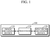
- FIG. 1 is a block diagram illustrating an apparatus for measuring particulate matter according to an example embodiment
- FIG. 2 is a diagram illustrating a structure of an image obtaining device according to an example embodiment
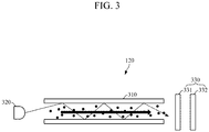
- FIG. 3 is a diagram illustrating a structure of a spectrum obtainer according to an example embodiment.
- the apparatus 100 for measuring particulate matter includes an image obtaining device 110, a spectrum obtaining device 120, and a processor 130.
- the image obtaining device 110 may obtain an image of particulate matter particles, contained in the introduced air, using lens-free imaging. For example, the image obtaining device 110 may charge the particulate matter particles contained in the introduced air, and may adsorb the charged particulate matter particles contained in the introduced air. Further, the image obtaining device 110 may emit light to the adsorbed particulate matter particles, and may generate an image of the particulate matter particles by receiving light having passed through the particulate matter particles or light reflected or scattered from the particulate matter particles.
- the image obtaining device 110 includes a particulate matter adsorbing device 210, a light source 220, and an image generating device 230.
- the particulate matter adsorbing device 210 may charge the particulate matter particles, and may adsorb the charged particulate matter particles.
- the particulate matter adsorbing device 210 may include a first electrode 211, to which either one of a positive polarity or a negative polarity is applied to charge the particulate matter particles, and a second electrode 212, to which the other one of the positive polarity and the negative polarity is applied to adsorb the charged particulate matter particles.
- an electric field may be generated between the first electrode 211 and the second electrode 212.
- the particulate matter particles may be electrically charged while passing through the first electrode 211.
- the polarity, applied to the first electrode 211 is a positive polarity
- the particulate matter particles are positively (+) charged
- the polarity, applied to the first electrode 211 is a negative polarity
- the particulate matter particles are negatively (-) charged.
- the charged particulate matter particles may be adsorbed on the second electrode 212.
- a polarity, applied to the second electrode 212, is opposite to a polarity applied to the first electrode 211, such that the second electrode 212 may have electrical properties which are opposite to those of the charged particulate matter particles. Accordingly, the particulate matter particles, which are electrically charged while passing through the first electrode 211, may be adsorbed automatically on the second electrode 212.
- the first electrode 211 may have a bar shape as illustrated in FIG. 2 .
- the first electrode 211 is not limited thereto, and may have various shapes, such as a plate shape having holes such that air containing particulate matter particles may pass therethrough, a grid shape, and the like.
- the second electrode 212 may have a plate shape, such that the charged particulate matter particles may be adsorbed thereon.
- the first electrode 211 and the second electrode 212 may be formed as a transparent electrode, to not obstruct the passage of light.
- the first electrode 211 and the second electrode 212 may be made of indium tin oxide (ITO), indium zinc oxide (IZO), stannic oxide (SnO 2 ), zinc oxide (ZnO), graphene, silver nanowire, conductive polymer (e.g., PEDOT:PSS), carbon nanotube, and the like.
- FIG. 2 illustrates two electrodes 211 and 212, this is merely an example, and the number of electrodes is not limited thereto.
- the light source 220 may emit light to the particulate matter particles adsorbed on the second electrode 212.
- the light source 220 may include one or more light sources.
- each light source may emit light of a predetermined wavelength, for example, visible light, near-infrared light, mid-infrared light, and the like, to the particulate matter particles adsorbed on the second electrode 212.
- wavelengths of light emitted by each light source may vary depending on the measurement purpose or types of analytes.
- each light source is not necessarily formed of a single light-emitting body, and may be formed of an array of a plurality of light-emitting bodies.
- each light source is formed of a plurality of light-emitting bodies
- the plurality of light-emitting bodies may emit light of the same wavelength or light of different wavelengths.
- some of the plurality of light-emitting bodies may emit light of the same wavelength, and others may emit light of different wavelengths.
- each light source may include a light emitting diode (LED), a laser diode, a phosphor, and the like, but this is merely an example, and the light source is not limited thereto.
- the light source 220 may further include a filter, for example, a clean-up filter, a bandpass filter, and the like, for selecting light of a specific wavelength, and/or an optical element, for example, reflecting mirror, and the like, for directing the emitted light toward a desired position.
- a filter for example, a clean-up filter, a bandpass filter, and the like, for selecting light of a specific wavelength
- an optical element for example, reflecting mirror, and the like, for directing the emitted light toward a desired position.
- the image generating device 230 may generate an image of the particulate matter particles by receiving light, having passed through the particulate matter particles adsorbed on the second electrode 212, or light reflected or scattered from the particulate matter particles adsorbed on the second electrode 212.
- the image generating device 230 may generate a hologram image of the particulate matter particles by receiving light having passed through, or reflected or scattered from, the particulate matter particles adsorbed on the second electrode 212, and may reconstruct the hologram image based on scattering characteristics of the particulate matter particles.
- the image generating device 230 may improve the resolution of the image by using a machine learning algorithm such as deep learning, and the like.
- the image generating device 230 may be disposed below the second electrode 212.
- the image generating device 230 may be disposed adjacent to a bottom portion of the second electrode 212.
- the image generating device 230 may include at least one of a charge-coupled device (CCD) and a complementary metal oxide semiconductor (CMOS).
- CCD charge-coupled device
- CMOS complementary metal oxide semiconductor
- the spectrum obtaining device 120 may obtain a Raman spectrum of the particulate matter particles contained in the introduced air.
- the spectrum obtaining device 120 may emit light to the particulate matter particles contained in the introduced air, and may generate a Raman spectrum of the particulate matter particles by receiving Raman scattered light of the particulate matter particles.
- the spectrum obtaining device 120 may include a waveguide 310, a light source 230, and a spectrum generating device 330.
- the particulate matter particles are introduced into the waveguide 310, and the waveguide 310 may transmit Raman scattered light of the particulate matter particles, which is produced by light emitted by the light source 320, to the spectrum generating device 330.
- the waveguide 310 may be formed as a hollow conduit having a relatively high conductivity.
- the particulate matter particles may flow from an inlet of the waveguide 310 to an outlet thereof, and may be discharged to the outside from the outlet of the waveguide 310.
- the light source 320 may emit light to the particulate matter particles introduced into the waveguide 310.
- the light source 320 may include one or more light sources.
- each light source may emit light of a predetermined wavelength, for example, visible light, near-infrared light, mid-infrared light, and the like, to the particulate matter particles introduced into the waveguide 310.
- wavelengths of light emitted by each light source may vary depending on the measurement purpose or types of analytes.
- each light source is not necessarily formed of a single light-emitting body, and may be formed of an array of a plurality of light-emitting bodies.
- each light source is formed of a plurality of light-emitting bodies
- the plurality of light-emitting bodies may emit light of the same wavelength or light of different wavelengths.
- some of the plurality of light-emitting bodies may emit light of the same wavelength, and others may emit light of different wavelengths.
- each light source may include a light emitting diode (LED), a laser diode, a phosphor, and the like, but this is merely an example, and the light source is not limited thereto.
- the light source 320 may further include a filter, for example, a clean-up filter, a bandpass filter, and the like, for selecting light of a specific wavelength, and/or an optical element, for example, reflecting mirror, and the like, for directing the emitted light toward a desired position.
- a filter for example, a clean-up filter, a bandpass filter, and the like, for selecting light of a specific wavelength
- an optical element for example, reflecting mirror, and the like, for directing the emitted light toward a desired position.
- the spectrum generating device 330 may generate a Raman spectrum of the particulate matter particles by receiving the Raman scattered light of the particulate matter particles introduced into the waveguide 310. To this end, the spectrum generating device 330 may include a spectrometer 331 and a generating device 332.
- the spectrometer 331 may receive the Raman scattered light of the particulate matter particles introduced into the waveguide 310, and may separate the Raman scattered light into wavelengths.
- the spectrometer 331 may include at least one of a prism, a grating, a filter, and the like, but is not limited thereto.
- the generating device 332 may generate a Raman spectrum by receiving the Raman scattered light which is separated into wavelengths.
- the generating device 332 may include at least one a charge-coupled device (CCD) and a complementary metal oxide semiconductor (CMOS), but is not limited thereto.
- CCD charge-coupled device
- CMOS complementary metal oxide semiconductor
- the processor 130 may control the overall operation of the apparatus 100 for measuring particulate matter.
- the processor 130 may control the image obtaining device 110 to obtain an image of the particulate matter particles, and may control the spectrum obtaining device 120 to obtain a Raman spectrum of the particulate matter particles.
- the processor 130 may obtain information on the particulate matter particles by analyzing the obtained image and the obtained Raman spectrum of the particulate matter particles.
- the information on the particulate matter particles may include the size, concentration, components, and the like of the particulate matter particles.
- the processor 130 may determine the size and concentration of the particulate matter particles by analyzing the image of the particulate matter particles. For example, by determining the size and number of the particulate matter particles in the image of the particulate matter particles, the processor 130 may determine the size and concentration of the particulate matter particles contained in the introduced air.
- the processor 130 may determine the components of the particulate matter particles by analyzing the Raman spectrum of the particulate matter particles.
- a frequency, at which a Raman spectrum peak appears may vary depending on the components of the particles. Accordingly, by referring to information on the frequency, at which the Raman spectrum peak appears, for each component of the particles, the processor 130 may determine the components of the particulate matter particles. In this case, information on the frequency, at which the Raman spectrum peak appears, for each component of the particles may be derived experimentally, and may be stored in an internal or external memory of the processor 130.
- the processor 130 may remove noise from the Raman spectrum.
- the Raman spectrum of the particulate matter particles includes much noise, and the noise included in the Raman spectrum may be divided into simple additive noise derived from an external environment, and background noise derived from autofluorescence.
- the processor 130 may remove the simple additive noise from the Raman spectrum by using a low-pass filter, for example, moving average filter, and the like.
- the processor 130 may estimate a baseline of the Raman spectrum, and may remove the background noise by subtracting the estimated baseline from the Raman spectrum. In this case, the baseline may be estimated using a first-order differential method, a rolling-ball method, and the like.
- the first-order differential method uses characteristics of background noise exhibiting a gradual change over the entire range.
- a baseline is estimated by differentiating a spectrum, finding a significant peak, cutting out the corresponding peak area, and performing interpolation.
- a trace of a highest point of a hypothetical ball that rolls underneath a spectrum is considered as a baseline.
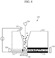
- FIG. 4 is a diagram illustrating a structure of an apparatus for measuring particulate matter according to an example embodiment.
- the apparatus for measuring particulate matter of FIG. 4 may be an example of the structure of the apparatus 100 for measuring particulate matter of FIG. 1 .
- a first electrode 211 is disposed near an inlet of a structure 410, into which air is introduced, and the second electrode 212 may be disposed below the structure 410.
- the particulate matter particles, contained in the introduced air may be electrically charged while passing through the first electrode 211.
- the charge particulate matter may flow downwards along the generated electric field and a passage of the structure 410, to be adsorbed on the second electrode 212.
- the light source 220 may be disposed near the inlet of the structure 410 to emit light to the particulate matter particles, which are adsorbed on the second electrode 212 disposed below the structure 410, and the image generating device 230 is dispose below the second electrode 212, and generates an image of the particulate matter particles by receiving light having passed through the second electrode 212.
- the waveguide 310 is disposed below the structure 410 in a direction parallel to the second electrode 212. Once the image of the particulate matter particles is obtained, and the electric field generated between the first electrode 211 and the second electrode 212 is removed, the particulate matter particles adsorbed on the second electrode 212 are desorbed to be introduced into the waveguide 310, and then may flow along the waveguide 310 to be discharged to the outside. That is, the waveguide 310 may function as a discharge port for the particulate matter particles.
- the light source 320 may be disposed near the inlet of the waveguide 310 to emit light to the particulate matter particles introduced into the waveguide 310, and the spectrum generating device 330 is disposed near an outlet of the waveguide 310 to receive Raman scattered light of the particulate matter particles, and may generate a Raman spectrum of the particulate matter particles.
- the apparatus 100 for measuring particulate matter may include a blocking part 420 for blocking holes except for the inlet of the waveguide 310.
- the blocking part 420 may be made of a transparent material so as not to affect the passage of light, or may be formed as a filter for passing light of a predetermined wavelength.
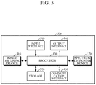
- FIG. 5 is a block diagram illustrating an apparatus for measuring particulate matter according to another embodiment of the present disclosure.
- the apparatus 500 for measuring particulate matter includes the image obtaining device 110, the spectrum obtaining device 120, the processor 130, an input interface 510, a storage 520, a communication interface 530, and an output interface 540.
- the image obtaining device 110, the spectrum obtaining device 120, and the processor 130 are described above with reference to FIGS. 1 to 4 , such that detailed description thereof will be omitted.
- the input interface 510 may receive input of various operation signals from a user.
- the input interface 510 may include a keypad, a dome switch, a static pressure or capacitance touch pad, a jog wheel, a jog switch, a hardware (H/W) button, and the like.
- the touch pad which forms a layer structure with a display, may be a touch screen.
- the storage 520 may store programs or commands for operation of the apparatus 500 for measuring particulate matter, and may store data input to and processed by the apparatus 500 for measuring particulate matter. Further, the storage 520 may store image data obtained by the image obtaining device 110, Raman spectrum data obtained by the spectrum obtaining device 120, information on particulate matter particles determined by the processor 130, data required for the processor 130 to determine the information on particulate matter particles, for example, information on a frequency, at which a Raman spectrum peak appears, for each component of the particles, and the like.
- the storage 520 may include at least one storage medium of a flash memory type memory, a hard disk type memory, a multimedia card micro type memory, a card type memory (e.g., an SD memory, an XD memory, etc.), a random access memory (RAM), a static random access memory (SRAM), a read only memory (ROM), an electrically erasable programmable read only memory (EEPROM), a programmable read only memory (PROM), a magnetic memory, a magnetic disk, and an optical disk, and the like.
- the apparatus 500 for measuring particulate matter may operate an external storage medium, such as web storage and the like, which performs a storage function of the storage 520 on the Internet.
- the communication interface 530 may communicate with an external device.
- the communication interface 530 may transmit, to the external device, data input from a user through the input interface 510, the image data obtained by the image obtaining device 110, the Raman spectrum data obtained by the spectrum obtaining device 120, the information on particulate matter particles determined by the processor 130, the data required for the processor 130 to determine the information on particulate matter particles, for example, information on a frequency, at which a Raman spectrum peak appears, for each component of the particles, and the like; or may receive, from the external device, various data useful for determining the information on particulate matter particles.
- the external device may be equipment using the image data obtained by the image obtaining device 110, the Raman spectrum data obtained by the spectrum obtaining device 120, the information on particulate matter particles determined by the processor 130, the data required for the processor 130 to determine the information on particulate matter particles, for example, information on a frequency, at which a Raman spectrum peak appears, for each component of the particles, and the like, a printer to print out results, or a display to display the results.
- the external device may be a digital television (TV), a desktop computer, a cellular phone, a smartphone, a tablet personal computer (PC), a laptop computer, a personal digital assistant (PDA), a portable multimedia player (PMP), a navigation device, an MP3 player, a digital camera, a wearable device, and the like, but is not limited thereto.
- TV digital television
- PC tablet personal computer
- PDA personal digital assistant
- PMP portable multimedia player
- navigation device an MP3 player
- digital camera a wearable device
- the communication interface 530 may communicate with an external device by using Bluetooth communication, Bluetooth Low Energy (BLE) communication, near field communication (NFC), WLAN communication, Zigbee communication, infrared data association (IrDA) communication, Wi-Fi Direct (WFD) communication, ultra-wideband (UWB) communication, Ant+ communication, WIFI communication, radio frequency identification (RFID) communication, 3G communication, 4G communication, 5G communication, and the like.
- BLE Bluetooth Low Energy
- NFC near field communication
- WLAN Zigbee communication
- IrDA infrared data association
- Wi-Fi Direct Wi-Fi Direct
- UWB ultra-wideband
- Ant+ communication Ant+ communication
- WIFI radio frequency identification
- the output interface 540 may output the image data obtained by the image obtaining device 110, the Raman spectrum data obtained by the spectrum obtaining device 120, the information on particulate matter particles determined by the processor 130, the data required for the processor 130 to determine the information on particulate matter particles, for example, information on a frequency, at which a Raman spectrum peak appears, for each component of the particles, and the like.
- the output interface 540 may output the image data obtained by the image obtaining device 110, the Raman spectrum data obtained by the spectrum obtaining device 120, the information on particulate matter particles determined by the processor 130, the data required for the processor 130 to determine the information on particulate matter particles, for example, information on a frequency, at which a Raman spectrum peak appears, for each component of the particles, and the like by using at least one of an acoustic method, a visual method, and a tactile method.
- the output interface 540 may include a display, a speaker, a vibrator, and the like.
- FIG. 6 is a flowchart illustrating a method of measuring particulate matter according to an example embodiment.
- the method of measuring particulate matter of FIG. 6 may be performed by the apparatus 100 or 500 for measuring particulate matter of FIG. 1 or FIG. 5 .
- the apparatus for measuring particulate matter may obtain an image of particulate matter particles, contained in the introduced air, using lens-free imaging (610).
- the apparatus for measuring particulate matter may charge the particulate matter particles contained in the introduced air, and may adsorb the charged particulate matter particles.
- the apparatus for measuring particulate matter may emit light to the adsorbed particulate matter particles, and may generate an image of the particulate matter particles by receiving light having passed through, or reflected or scattered from, the particulate matter particles.
- the apparatus for measuring particulate matter may generate an electric field between the first electrode and the second electrode.
- the particulate matter particles may be electrically charged while passing through the first electrode, and the charged particulate matter particles may be adsorbed on the second electrode.
- the apparatus for measuring particulate matter may emit light to the particulate matter particles adsorbed on the second electrode, and may generate an image of the particulate matter particles by receiving light having passed through the particulate matter particles or light reflected or scattered from the particulate matter particles.
- the apparatus for measuring particulate matter may generate a hologram image of the particulate matter particles by receiving light having passed through, or reflected or scattered from, the particulate matter particles, and may reconstruct the hologram image based on scattering characteristics of the particulate matter particles.
- the apparatus for measuring particulate matter may obtain a Raman spectrum of the particulate matter particles contained in the introduced air (620).
- the apparatus for measuring particulate matter may emit light to the particulate matter particles, and may generate a Raman spectrum of the particulate matter particles by receiving Raman scattered light of the particulate matter particles.
- the waveguide may function as a discharge port for the particulate matter particles.
- the apparatus for measuring particulate matter may obtain information on the particulate matter particles by analyzing the obtained image and Raman spectrum of the particulate matter particles (630).
- the information on the particulate matter particles may include the size, concentration, components, and the like of the particulate matter particles.
- the apparatus for measuring particulate matter may determine the size and concentration of the particulate matter particles by analyzing the image of the particulate matter particles. For example, by determining the size and number of the particulate matter particles in the image of the particulate matter particles, the apparatus for measuring particulate matter may determine the size and concentration of the particulate matter particles contained in the introduced air.
- the apparatus for measuring particulate matter may determine the components of the particulate matter particles by analyzing the Raman spectrum of the particulate matter particles.
- a frequency, at which a Raman spectrum peak appears may vary depending on the components of the particles. Accordingly, by referring to information on the frequency, at which the Raman spectrum peak appears, for each component of the particles, the apparatus for measuring particulate matter may determine the components of the particulate matter particles. In this case, information on the frequency, at which the Raman spectrum peak appears, for each component of the particles may be derived experimentally, and may be stored in an internal or external memory.
- the present disclosure can be realized as a computer-readable code written on a computer-readable recording medium. Codes and code segments needed for realizing the present disclosure can be easily deduced by computer programmers of ordinary skill in the art.
- the computer-readable recording medium may be any type of recording device in which data is stored in a computer-readable manner. Examples of the computer-readable recording medium include a ROM, a RAM, a CD-ROM, a magnetic tape, a floppy disc, an optical disk, and the like. Further, the computer-readable recording medium can be distributed over a plurality of computer systems connected to a network so that a computer-readable recording medium is written thereto and executed therefrom in a decentralized manner.
Landscapes
- Chemical & Material Sciences (AREA)
- Health & Medical Sciences (AREA)
- Physics & Mathematics (AREA)
- General Physics & Mathematics (AREA)
- Biochemistry (AREA)
- Analytical Chemistry (AREA)
- Life Sciences & Earth Sciences (AREA)
- General Health & Medical Sciences (AREA)
- Immunology (AREA)
- Pathology (AREA)
- Dispersion Chemistry (AREA)
- Nuclear Medicine, Radiotherapy & Molecular Imaging (AREA)
- Spectroscopy & Molecular Physics (AREA)
- Investigating, Analyzing Materials By Fluorescence Or Luminescence (AREA)
Applications Claiming Priority (1)
| Application Number | Priority Date | Filing Date | Title |
|---|---|---|---|
| KR1020190094822A KR102739071B1 (ko) | 2019-08-05 | 2019-08-05 | 미세먼지 측정 장치 및 방법 |
Publications (2)
| Publication Number | Publication Date |
|---|---|
| EP3772643A1 true EP3772643A1 (fr) | 2021-02-10 |
| EP3772643B1 EP3772643B1 (fr) | 2022-03-09 |
Family
ID=70738346
Family Applications (1)
| Application Number | Title | Priority Date | Filing Date |
|---|---|---|---|
| EP20174912.4A Active EP3772643B1 (fr) | 2019-08-05 | 2020-05-15 | Appareil et procédé de mesure de matière particulaire |
Country Status (4)
| Country | Link |
|---|---|
| US (1) | US11112363B2 (fr) |
| EP (1) | EP3772643B1 (fr) |
| KR (1) | KR102739071B1 (fr) |
| CN (1) | CN112326515B (fr) |
Families Citing this family (3)
| Publication number | Priority date | Publication date | Assignee | Title |
|---|---|---|---|---|
| KR102735781B1 (ko) * | 2022-07-20 | 2024-11-28 | 주식회사 사이버네틱스이미징시스템즈 | 병리학 시료의 스캔 이미징 및 라만 신호 동시 획득 시스템 및 방법 |
| KR102744510B1 (ko) * | 2022-11-15 | 2024-12-18 | 허목 | 에너지 절약형 IoT 미세 먼지 측정장치 |
| KR102858909B1 (ko) | 2025-03-13 | 2025-09-12 | 서울특별시 | 미세먼지에 포함된 미세플라스틱 분석방법 |
Citations (1)
| Publication number | Priority date | Publication date | Assignee | Title |
|---|---|---|---|---|
| WO2018118934A1 (fr) * | 2016-12-19 | 2018-06-28 | Massachusetts Institute Of Technology | Systèmes et procédés de surveillance de matière particulaire dans l'air |
Family Cites Families (37)
| Publication number | Priority date | Publication date | Assignee | Title |
|---|---|---|---|---|
| US4786472A (en) | 1986-08-21 | 1988-11-22 | R. J. Reynolds Tobacco Company | Air sampling device |
| DE4339834A1 (de) | 1993-11-23 | 1995-05-24 | Rheinische Werkzeug & Maschf | Verfahren und Vorrichtung zur Korngrößenanalyse im Fein- und Feinstkornbereich |
| US5510611A (en) | 1994-02-25 | 1996-04-23 | Yokogawa Electric Corporation | Particle component analyzing apparatus, and equivalent particle diameter measuring method using same |
| JP2001066266A (ja) * | 1999-08-27 | 2001-03-16 | Shimadzu Corp | 浮遊粒子状物質測定装置 |
| EP1273901A1 (fr) * | 2001-07-02 | 2003-01-08 | Université de Liège | Méthode et appareillage pour mesure automatique de granulométrie et de morphométrie de particules |
| JP4085941B2 (ja) | 2003-09-17 | 2008-05-14 | 株式会社日立製作所 | 分析装置 |
| KR100532287B1 (ko) * | 2003-09-17 | 2005-11-29 | 삼성전자주식회사 | 휴대용 카메라 모듈의 미세 이물질 제거 장치 및 방법 |
| KR20060105755A (ko) * | 2003-11-21 | 2006-10-11 | 코닌클리케 필립스 일렉트로닉스 엔.브이. | 전기영동 디스플레이 디바이스에서 에지 영상 잔상을감소하기 위한 방법과 장치 |
| KR100567788B1 (ko) * | 2004-02-13 | 2006-04-05 | 주식회사 현대교정인증기술원 | 입자측정기 및 입자측정방법 |
| DE102004012105A1 (de) | 2004-03-12 | 2005-09-22 | Führer, Gerhard, Dr. | Probenentnahme-Verfahren und Analyse-Kit zur Durchführung einer Schadstoffanalyse in Innenräumen |
| CN101326276A (zh) * | 2005-12-12 | 2008-12-17 | 美利肯公司 | 清洁装置 |
| CN100555031C (zh) * | 2006-05-23 | 2009-10-28 | 宸鸿光电科技股份有限公司 | 令透明基板上透明电极不可见的处理方法 |
| JP4859626B2 (ja) | 2006-10-31 | 2012-01-25 | 三菱重工業株式会社 | 微細粒子成分分析装置 |
| CN101715550B (zh) | 2007-05-12 | 2012-03-14 | 罗杰·L.·昂格尔 | 紧凑型、低成本的粒子传感器 |
| WO2009037701A2 (fr) * | 2007-09-20 | 2009-03-26 | Novatrans Group Sa | Dispositif et procédé de détection d'image |
| JP2009145414A (ja) * | 2007-12-11 | 2009-07-02 | Bridgestone Corp | 情報表示用パネルの製造方法およびそれに用いる粒子状表示媒体充填装置 |
| WO2012016159A2 (fr) | 2010-07-30 | 2012-02-02 | Buglab Llc | Capteur optique pour la détermination rapide de la concentration particulaire |
| JP5509163B2 (ja) * | 2011-08-11 | 2014-06-04 | 京セラドキュメントソリューションズ株式会社 | 正帯電性トナー |
| JP6284294B2 (ja) * | 2012-05-31 | 2018-02-28 | イー インク コーポレイション | 画像表示媒体の駆動装置、画像表示装置、及び駆動プログラム |
| WO2014024556A1 (fr) | 2012-08-07 | 2014-02-13 | ソニー株式会社 | Procédé de surveillance d'écoulement laminaire pour dispositif de mesure de microparticules, procédé d'analyse de microparticules et dispositif de mesure de microparticules |
| CN103855601A (zh) * | 2012-12-03 | 2014-06-11 | 中国科学院大连化学物理研究所 | 一种降低氢气受激拉曼散射阈值的方法 |
| EP2824445B1 (fr) * | 2013-07-08 | 2016-03-02 | Fei Company | Microscopie à particules chargées combinée avec spectroscopie raman |
| CN103940799B (zh) * | 2014-03-10 | 2016-08-24 | 北京理工大学 | 激光双轴共焦布里渊-拉曼光谱测量方法与装置 |
| KR101551289B1 (ko) | 2014-05-22 | 2015-09-09 | 한국과학기술연구원 | 미세 입자 측정 장치 및 이를 이용한 미세 입자 측정 방법 |
| KR102002665B1 (ko) | 2015-01-23 | 2019-10-01 | 전자부품연구원 | 미세입자 및 가스입자 측정 시스템 |
| KR101678175B1 (ko) | 2015-02-25 | 2016-11-21 | (주)켄텍 | 중금속 시료 포집이 동시 가능한 미세먼지 자동 측정 장치 |
| WO2016174523A1 (fr) * | 2015-04-27 | 2016-11-03 | Illumina France Sarl | Systèmes et procédés pour identifier et/ou suivre des particules dans une gouttelette, la particule pouvant être une cellule |
| WO2017051327A1 (fr) | 2015-09-22 | 2017-03-30 | Imageprovision Technology Pvt. Ltd. | Procédé et système de détection et classification de particules sur la base d'un traitement d'images microphotographiques |
| US9921144B2 (en) | 2016-06-29 | 2018-03-20 | Honeywell International Inc. | Particulate matter detector |
| CN106139145B (zh) * | 2016-07-14 | 2020-03-10 | 国家纳米科学中心 | 激子-等离激元耦合体系、其构建方法及利用该耦合体系增强光敏剂单线态氧产生的方法 |
| CN106404616B (zh) | 2016-08-31 | 2018-12-25 | 孙扬 | 一种大气细颗粒物(pm2.5)排放源解析定位的方法 |
| KR101721607B1 (ko) | 2016-11-10 | 2017-04-03 | 대한민국 | 회전형 미세먼지 성분 분석 장치 및 그를 이용한 분석 방법 |
| CN108153186A (zh) | 2017-12-12 | 2018-06-12 | 大连理创科技有限公司 | 一种空气质量监控系统 |
| CN107942597A (zh) * | 2018-01-02 | 2018-04-20 | 京东方科技集团股份有限公司 | 电子纸及其显示方法、显示装置 |
| KR101914971B1 (ko) | 2018-03-23 | 2018-11-06 | 주식회사 대은계전 | 환경 모니터링 및 계측 제어 장치 |
| CN109211847B (zh) * | 2018-09-29 | 2020-06-30 | 西北大学 | 一种采用分析装置进行单个悬浮颗粒化学成分分析的方法 |
| CN109239053B (zh) * | 2018-10-29 | 2020-08-07 | 中国科学院上海技术物理研究所 | 一种基于液芯波导拉曼光谱的航天员尿液检测系统 |
-
2019
- 2019-08-05 KR KR1020190094822A patent/KR102739071B1/ko active Active
-
2020
- 2020-03-16 US US16/819,618 patent/US11112363B2/en active Active
- 2020-03-30 CN CN202010240300.2A patent/CN112326515B/zh active Active
- 2020-05-15 EP EP20174912.4A patent/EP3772643B1/fr active Active
Patent Citations (1)
| Publication number | Priority date | Publication date | Assignee | Title |
|---|---|---|---|---|
| WO2018118934A1 (fr) * | 2016-12-19 | 2018-06-28 | Massachusetts Institute Of Technology | Systèmes et procédés de surveillance de matière particulaire dans l'air |
Non-Patent Citations (3)
| Title |
|---|
| ADAM HAMMOND ET AL: "Holographic deflection imaging measurement of electric charge on aerosol particles", EXPERIMENTS IN FLUIDS., vol. 60, no. 6, 27 May 2019 (2019-05-27), DE, XP055750899, ISSN: 0723-4864, DOI: 10.1007/s00348-019-2744-z * |
| STEPHANIE L. WRIGHT ET AL: "Raman Spectral Imaging for the Detection of Inhalable Microplastics in Ambient Particulate Matter Samples", ENVIRONMENTAL SCIENCE & TECHNOLOGY, vol. 53, no. 15, 11 July 2019 (2019-07-11), US, pages 8947 - 8956, XP055745800, ISSN: 0013-936X, DOI: 10.1021/acs.est.8b06663 * |
| VASANTHI SIVAPRAKASAM ET AL: "Surface Enhanced Raman Spectroscopy of Individual Suspended Aerosol Particles", THE JOURNAL OF PHYSICAL CHEMISTRY C, vol. 121, no. 40, 29 September 2017 (2017-09-29), US, pages 22326 - 22334, XP055751076, ISSN: 1932-7447, DOI: 10.1021/acs.jpcc.7b05310 * |
Also Published As
| Publication number | Publication date |
|---|---|
| KR20210016716A (ko) | 2021-02-17 |
| US11112363B2 (en) | 2021-09-07 |
| KR102739071B1 (ko) | 2024-12-06 |
| CN112326515A (zh) | 2021-02-05 |
| EP3772643B1 (fr) | 2022-03-09 |
| CN112326515B (zh) | 2024-05-31 |
| US20210041365A1 (en) | 2021-02-11 |
Similar Documents
| Publication | Publication Date | Title |
|---|---|---|
| US11112363B2 (en) | Apparatus and method for measuring particulate matter | |
| Al Mamun et al. | Sensors and systems for wearable environmental monitoring toward IoT-enabled applications: A review | |
| US20250281057A1 (en) | Concentric architecture for optical sensing | |
| Xue et al. | Advances in miniaturized computational spectrometers | |
| EP3686772B1 (fr) | Classification sur dispositif de schémas de mouvement de bout du doigt dans des gestes en temps réel | |
| CN111936892B (zh) | 包括使用菲涅耳透镜的光学传感器的电子设备 | |
| US9427192B2 (en) | Touch-sensitive device and method | |
| US9585581B1 (en) | Real-time biometric detection of oscillatory phenomena and voltage events | |
| JP2015516714A (ja) | モバイルデバイスに関連付けられた体感品質の測定 | |
| US20160198129A1 (en) | Room monitoring device | |
| US11397492B2 (en) | Enhanced mutual capacitance touch screen display with shape detection and methods for use therewith | |
| Chen et al. | Efring: Enabling thumb-to-index-finger microgesture interaction through electric field sensing using single smart ring | |
| EP3770579B1 (fr) | Appareil et procédé de mesure de matière particulaire | |
| US20240372919A1 (en) | Fine grained network management to edge device features | |
| US12135852B1 (en) | Spatial filtering a touch signal of a touch screen display | |
| CN106292871B (zh) | 一种可实现转腕亮屏的智能手环 | |
| Matthies et al. | Prototyping smart eyewear with capacitive sensing for facial and head gesture detection | |
| Li et al. | Indoor health monitoring with vlc-based passive posture monitoring | |
| CN106843503A (zh) | 一种显示装置及其控制方法 | |
| KR20170040922A (ko) | 회전 입력 측정 방법 및 장치 | |
| Scott et al. | Neurocamtags: Long-range, battery-free, wireless sensing with neuromorphic cameras | |
| CN113127272B (zh) | 屏幕检测方法和屏幕检测的电子设备 | |
| EP2610717A1 (fr) | Dispositif de communication pour équipement comprenant un écran tactile, système de communication | |
| US20200124471A1 (en) | Compact spectrometer unit and bio-signal measuring apparatus | |
| US20210137445A1 (en) | Apparatus and method for estimating skin barrier function |
Legal Events
| Date | Code | Title | Description |
|---|---|---|---|
| PUAI | Public reference made under article 153(3) epc to a published international application that has entered the european phase |
Free format text: ORIGINAL CODE: 0009012 |
|
| STAA | Information on the status of an ep patent application or granted ep patent |
Free format text: STATUS: THE APPLICATION HAS BEEN PUBLISHED |
|
| AK | Designated contracting states |
Kind code of ref document: A1 Designated state(s): AL AT BE BG CH CY CZ DE DK EE ES FI FR GB GR HR HU IE IS IT LI LT LU LV MC MK MT NL NO PL PT RO RS SE SI SK SM TR |
|
| AX | Request for extension of the european patent |
Extension state: BA ME |
|
| STAA | Information on the status of an ep patent application or granted ep patent |
Free format text: STATUS: REQUEST FOR EXAMINATION WAS MADE |
|
| 17P | Request for examination filed |
Effective date: 20210803 |
|
| RBV | Designated contracting states (corrected) |
Designated state(s): AL AT BE BG CH CY CZ DE DK EE ES FI FR GB GR HR HU IE IS IT LI LT LU LV MC MK MT NL NO PL PT RO RS SE SI SK SM TR |
|
| GRAP | Despatch of communication of intention to grant a patent |
Free format text: ORIGINAL CODE: EPIDOSNIGR1 |
|
| STAA | Information on the status of an ep patent application or granted ep patent |
Free format text: STATUS: GRANT OF PATENT IS INTENDED |
|
| INTG | Intention to grant announced |
Effective date: 20211125 |
|
| GRAS | Grant fee paid |
Free format text: ORIGINAL CODE: EPIDOSNIGR3 |
|
| GRAA | (expected) grant |
Free format text: ORIGINAL CODE: 0009210 |
|
| STAA | Information on the status of an ep patent application or granted ep patent |
Free format text: STATUS: THE PATENT HAS BEEN GRANTED |
|
| AK | Designated contracting states |
Kind code of ref document: B1 Designated state(s): AL AT BE BG CH CY CZ DE DK EE ES FI FR GB GR HR HU IE IS IT LI LT LU LV MC MK MT NL NO PL PT RO RS SE SI SK SM TR |
|
| REG | Reference to a national code |
Ref country code: CH Ref legal event code: EP Ref country code: AT Ref legal event code: REF Ref document number: 1474557 Country of ref document: AT Kind code of ref document: T Effective date: 20220315 |
|
| REG | Reference to a national code |
Ref country code: IE Ref legal event code: FG4D |
|
| REG | Reference to a national code |
Ref country code: DE Ref legal event code: R096 Ref document number: 602020002116 Country of ref document: DE |
|
| REG | Reference to a national code |
Ref country code: LT Ref legal event code: MG9D |
|
| REG | Reference to a national code |
Ref country code: NL Ref legal event code: MP Effective date: 20220309 |
|
| PG25 | Lapsed in a contracting state [announced via postgrant information from national office to epo] |
Ref country code: SE Free format text: LAPSE BECAUSE OF FAILURE TO SUBMIT A TRANSLATION OF THE DESCRIPTION OR TO PAY THE FEE WITHIN THE PRESCRIBED TIME-LIMIT Effective date: 20220309 Ref country code: RS Free format text: LAPSE BECAUSE OF FAILURE TO SUBMIT A TRANSLATION OF THE DESCRIPTION OR TO PAY THE FEE WITHIN THE PRESCRIBED TIME-LIMIT Effective date: 20220309 Ref country code: NO Free format text: LAPSE BECAUSE OF FAILURE TO SUBMIT A TRANSLATION OF THE DESCRIPTION OR TO PAY THE FEE WITHIN THE PRESCRIBED TIME-LIMIT Effective date: 20220609 Ref country code: LT Free format text: LAPSE BECAUSE OF FAILURE TO SUBMIT A TRANSLATION OF THE DESCRIPTION OR TO PAY THE FEE WITHIN THE PRESCRIBED TIME-LIMIT Effective date: 20220309 Ref country code: HR Free format text: LAPSE BECAUSE OF FAILURE TO SUBMIT A TRANSLATION OF THE DESCRIPTION OR TO PAY THE FEE WITHIN THE PRESCRIBED TIME-LIMIT Effective date: 20220309 Ref country code: BG Free format text: LAPSE BECAUSE OF FAILURE TO SUBMIT A TRANSLATION OF THE DESCRIPTION OR TO PAY THE FEE WITHIN THE PRESCRIBED TIME-LIMIT Effective date: 20220609 |
|
| REG | Reference to a national code |
Ref country code: AT Ref legal event code: MK05 Ref document number: 1474557 Country of ref document: AT Kind code of ref document: T Effective date: 20220309 |
|
| PG25 | Lapsed in a contracting state [announced via postgrant information from national office to epo] |
Ref country code: LV Free format text: LAPSE BECAUSE OF FAILURE TO SUBMIT A TRANSLATION OF THE DESCRIPTION OR TO PAY THE FEE WITHIN THE PRESCRIBED TIME-LIMIT Effective date: 20220309 Ref country code: GR Free format text: LAPSE BECAUSE OF FAILURE TO SUBMIT A TRANSLATION OF THE DESCRIPTION OR TO PAY THE FEE WITHIN THE PRESCRIBED TIME-LIMIT Effective date: 20220610 Ref country code: FI Free format text: LAPSE BECAUSE OF FAILURE TO SUBMIT A TRANSLATION OF THE DESCRIPTION OR TO PAY THE FEE WITHIN THE PRESCRIBED TIME-LIMIT Effective date: 20220309 |
|
| PG25 | Lapsed in a contracting state [announced via postgrant information from national office to epo] |
Ref country code: NL Free format text: LAPSE BECAUSE OF FAILURE TO SUBMIT A TRANSLATION OF THE DESCRIPTION OR TO PAY THE FEE WITHIN THE PRESCRIBED TIME-LIMIT Effective date: 20220309 |
|
| PG25 | Lapsed in a contracting state [announced via postgrant information from national office to epo] |
Ref country code: SM Free format text: LAPSE BECAUSE OF FAILURE TO SUBMIT A TRANSLATION OF THE DESCRIPTION OR TO PAY THE FEE WITHIN THE PRESCRIBED TIME-LIMIT Effective date: 20220309 Ref country code: SK Free format text: LAPSE BECAUSE OF FAILURE TO SUBMIT A TRANSLATION OF THE DESCRIPTION OR TO PAY THE FEE WITHIN THE PRESCRIBED TIME-LIMIT Effective date: 20220309 Ref country code: RO Free format text: LAPSE BECAUSE OF FAILURE TO SUBMIT A TRANSLATION OF THE DESCRIPTION OR TO PAY THE FEE WITHIN THE PRESCRIBED TIME-LIMIT Effective date: 20220309 Ref country code: PT Free format text: LAPSE BECAUSE OF FAILURE TO SUBMIT A TRANSLATION OF THE DESCRIPTION OR TO PAY THE FEE WITHIN THE PRESCRIBED TIME-LIMIT Effective date: 20220711 Ref country code: ES Free format text: LAPSE BECAUSE OF FAILURE TO SUBMIT A TRANSLATION OF THE DESCRIPTION OR TO PAY THE FEE WITHIN THE PRESCRIBED TIME-LIMIT Effective date: 20220309 Ref country code: EE Free format text: LAPSE BECAUSE OF FAILURE TO SUBMIT A TRANSLATION OF THE DESCRIPTION OR TO PAY THE FEE WITHIN THE PRESCRIBED TIME-LIMIT Effective date: 20220309 Ref country code: CZ Free format text: LAPSE BECAUSE OF FAILURE TO SUBMIT A TRANSLATION OF THE DESCRIPTION OR TO PAY THE FEE WITHIN THE PRESCRIBED TIME-LIMIT Effective date: 20220309 Ref country code: AT Free format text: LAPSE BECAUSE OF FAILURE TO SUBMIT A TRANSLATION OF THE DESCRIPTION OR TO PAY THE FEE WITHIN THE PRESCRIBED TIME-LIMIT Effective date: 20220309 |
|
| PG25 | Lapsed in a contracting state [announced via postgrant information from national office to epo] |
Ref country code: PL Free format text: LAPSE BECAUSE OF FAILURE TO SUBMIT A TRANSLATION OF THE DESCRIPTION OR TO PAY THE FEE WITHIN THE PRESCRIBED TIME-LIMIT Effective date: 20220309 Ref country code: IS Free format text: LAPSE BECAUSE OF FAILURE TO SUBMIT A TRANSLATION OF THE DESCRIPTION OR TO PAY THE FEE WITHIN THE PRESCRIBED TIME-LIMIT Effective date: 20220709 Ref country code: AL Free format text: LAPSE BECAUSE OF FAILURE TO SUBMIT A TRANSLATION OF THE DESCRIPTION OR TO PAY THE FEE WITHIN THE PRESCRIBED TIME-LIMIT Effective date: 20220309 |
|
| REG | Reference to a national code |
Ref country code: DE Ref legal event code: R097 Ref document number: 602020002116 Country of ref document: DE |
|
| PLBE | No opposition filed within time limit |
Free format text: ORIGINAL CODE: 0009261 |
|
| STAA | Information on the status of an ep patent application or granted ep patent |
Free format text: STATUS: NO OPPOSITION FILED WITHIN TIME LIMIT |
|
| REG | Reference to a national code |
Ref country code: BE Ref legal event code: MM Effective date: 20220531 |
|
| PG25 | Lapsed in a contracting state [announced via postgrant information from national office to epo] |
Ref country code: MC Free format text: LAPSE BECAUSE OF FAILURE TO SUBMIT A TRANSLATION OF THE DESCRIPTION OR TO PAY THE FEE WITHIN THE PRESCRIBED TIME-LIMIT Effective date: 20220309 Ref country code: LU Free format text: LAPSE BECAUSE OF NON-PAYMENT OF DUE FEES Effective date: 20220515 Ref country code: DK Free format text: LAPSE BECAUSE OF FAILURE TO SUBMIT A TRANSLATION OF THE DESCRIPTION OR TO PAY THE FEE WITHIN THE PRESCRIBED TIME-LIMIT Effective date: 20220309 |
|
| 26N | No opposition filed |
Effective date: 20221212 |
|
| PG25 | Lapsed in a contracting state [announced via postgrant information from national office to epo] |
Ref country code: SI Free format text: LAPSE BECAUSE OF FAILURE TO SUBMIT A TRANSLATION OF THE DESCRIPTION OR TO PAY THE FEE WITHIN THE PRESCRIBED TIME-LIMIT Effective date: 20220309 |
|
| PG25 | Lapsed in a contracting state [announced via postgrant information from national office to epo] |
Ref country code: IE Free format text: LAPSE BECAUSE OF NON-PAYMENT OF DUE FEES Effective date: 20220515 |
|
| PG25 | Lapsed in a contracting state [announced via postgrant information from national office to epo] |
Ref country code: BE Free format text: LAPSE BECAUSE OF NON-PAYMENT OF DUE FEES Effective date: 20220531 |
|
| P01 | Opt-out of the competence of the unified patent court (upc) registered |
Effective date: 20230520 |
|
| PG25 | Lapsed in a contracting state [announced via postgrant information from national office to epo] |
Ref country code: IT Free format text: LAPSE BECAUSE OF FAILURE TO SUBMIT A TRANSLATION OF THE DESCRIPTION OR TO PAY THE FEE WITHIN THE PRESCRIBED TIME-LIMIT Effective date: 20220309 |
|
| REG | Reference to a national code |
Ref country code: CH Ref legal event code: PL |
|
| PG25 | Lapsed in a contracting state [announced via postgrant information from national office to epo] |
Ref country code: LI Free format text: LAPSE BECAUSE OF NON-PAYMENT OF DUE FEES Effective date: 20230531 Ref country code: CH Free format text: LAPSE BECAUSE OF NON-PAYMENT OF DUE FEES Effective date: 20230531 |
|
| PG25 | Lapsed in a contracting state [announced via postgrant information from national office to epo] |
Ref country code: MK Free format text: LAPSE BECAUSE OF FAILURE TO SUBMIT A TRANSLATION OF THE DESCRIPTION OR TO PAY THE FEE WITHIN THE PRESCRIBED TIME-LIMIT Effective date: 20220309 Ref country code: CY Free format text: LAPSE BECAUSE OF FAILURE TO SUBMIT A TRANSLATION OF THE DESCRIPTION OR TO PAY THE FEE WITHIN THE PRESCRIBED TIME-LIMIT Effective date: 20220309 |
|
| PG25 | Lapsed in a contracting state [announced via postgrant information from national office to epo] |
Ref country code: HU Free format text: LAPSE BECAUSE OF FAILURE TO SUBMIT A TRANSLATION OF THE DESCRIPTION OR TO PAY THE FEE WITHIN THE PRESCRIBED TIME-LIMIT; INVALID AB INITIO Effective date: 20200515 |
|
| PG25 | Lapsed in a contracting state [announced via postgrant information from national office to epo] |
Ref country code: TR Free format text: LAPSE BECAUSE OF FAILURE TO SUBMIT A TRANSLATION OF THE DESCRIPTION OR TO PAY THE FEE WITHIN THE PRESCRIBED TIME-LIMIT Effective date: 20220309 |
|
| PG25 | Lapsed in a contracting state [announced via postgrant information from national office to epo] |
Ref country code: MT Free format text: LAPSE BECAUSE OF FAILURE TO SUBMIT A TRANSLATION OF THE DESCRIPTION OR TO PAY THE FEE WITHIN THE PRESCRIBED TIME-LIMIT Effective date: 20220309 |
|
| PGFP | Annual fee paid to national office [announced via postgrant information from national office to epo] |
Ref country code: DE Payment date: 20250408 Year of fee payment: 6 |
|
| PGFP | Annual fee paid to national office [announced via postgrant information from national office to epo] |
Ref country code: GB Payment date: 20250410 Year of fee payment: 6 |
|
| PGFP | Annual fee paid to national office [announced via postgrant information from national office to epo] |
Ref country code: FR Payment date: 20250409 Year of fee payment: 6 |