EP3772593A1 - Motorisiertes arbeitsgerät mit verstärktem kühllüftergehäuse - Google Patents
Motorisiertes arbeitsgerät mit verstärktem kühllüftergehäuse Download PDFInfo
- Publication number
- EP3772593A1 EP3772593A1 EP19190671.8A EP19190671A EP3772593A1 EP 3772593 A1 EP3772593 A1 EP 3772593A1 EP 19190671 A EP19190671 A EP 19190671A EP 3772593 A1 EP3772593 A1 EP 3772593A1
- Authority
- EP
- European Patent Office
- Prior art keywords
- side wall
- connecting strut
- tool according
- fan
- drive motor
- Prior art date
- Legal status (The legal status is an assumption and is not a legal conclusion. Google has not performed a legal analysis and makes no representation as to the accuracy of the status listed.)
- Granted
Links
Images


Classifications
-
- F—MECHANICAL ENGINEERING; LIGHTING; HEATING; WEAPONS; BLASTING
- F04—POSITIVE - DISPLACEMENT MACHINES FOR LIQUIDS; PUMPS FOR LIQUIDS OR ELASTIC FLUIDS
- F04D—NON-POSITIVE-DISPLACEMENT PUMPS
- F04D29/00—Details, component parts, or accessories
- F04D29/40—Casings; Connections of working fluid
- F04D29/42—Casings; Connections of working fluid for radial or helico-centrifugal pumps
- F04D29/4206—Casings; Connections of working fluid for radial or helico-centrifugal pumps especially adapted for elastic fluid pumps
- F04D29/4226—Fan casings
-
- F—MECHANICAL ENGINEERING; LIGHTING; HEATING; WEAPONS; BLASTING
- F01—MACHINES OR ENGINES IN GENERAL; ENGINE PLANTS IN GENERAL; STEAM ENGINES
- F01P—COOLING OF MACHINES OR ENGINES IN GENERAL; COOLING OF INTERNAL-COMBUSTION ENGINES
- F01P1/00—Air cooling
- F01P1/02—Arrangements for cooling cylinders or cylinder heads, e.g. ducting cooling-air from its pressure source to cylinders or along cylinders
-
- F—MECHANICAL ENGINEERING; LIGHTING; HEATING; WEAPONS; BLASTING
- F01—MACHINES OR ENGINES IN GENERAL; ENGINE PLANTS IN GENERAL; STEAM ENGINES
- F01P—COOLING OF MACHINES OR ENGINES IN GENERAL; COOLING OF INTERNAL-COMBUSTION ENGINES
- F01P5/00—Pumping cooling-air or liquid coolants
- F01P5/02—Pumping cooling-air; Arrangements of cooling-air pumps, e.g. fans or blowers
- F01P5/06—Guiding or ducting air to, or from, ducted fans
-
- F—MECHANICAL ENGINEERING; LIGHTING; HEATING; WEAPONS; BLASTING
- F02—COMBUSTION ENGINES; HOT-GAS OR COMBUSTION-PRODUCT ENGINE PLANTS
- F02B—INTERNAL-COMBUSTION PISTON ENGINES; COMBUSTION ENGINES IN GENERAL
- F02B63/00—Adaptations of engines for driving pumps, hand-held tools or electric generators; Portable combinations of engines with engine-driven devices
- F02B63/02—Adaptations of engines for driving pumps, hand-held tools or electric generators; Portable combinations of engines with engine-driven devices for hand-held tools
-
- F—MECHANICAL ENGINEERING; LIGHTING; HEATING; WEAPONS; BLASTING
- F04—POSITIVE - DISPLACEMENT MACHINES FOR LIQUIDS; PUMPS FOR LIQUIDS OR ELASTIC FLUIDS
- F04D—NON-POSITIVE-DISPLACEMENT PUMPS
- F04D25/00—Pumping installations or systems
- F04D25/02—Units comprising pumps and their driving means
-
- F—MECHANICAL ENGINEERING; LIGHTING; HEATING; WEAPONS; BLASTING
- F04—POSITIVE - DISPLACEMENT MACHINES FOR LIQUIDS; PUMPS FOR LIQUIDS OR ELASTIC FLUIDS
- F04D—NON-POSITIVE-DISPLACEMENT PUMPS
- F04D29/00—Details, component parts, or accessories
- F04D29/60—Mounting; Assembling; Disassembling
- F04D29/62—Mounting; Assembling; Disassembling of radial or helico-centrifugal pumps
- F04D29/624—Mounting; Assembling; Disassembling of radial or helico-centrifugal pumps especially adapted for elastic fluid pumps
- F04D29/626—Mounting or removal of fans
-
- B—PERFORMING OPERATIONS; TRANSPORTING
- B25—HAND TOOLS; PORTABLE POWER-DRIVEN TOOLS; MANIPULATORS
- B25F—COMBINATION OR MULTI-PURPOSE TOOLS NOT OTHERWISE PROVIDED FOR; DETAILS OR COMPONENTS OF PORTABLE POWER-DRIVEN TOOLS NOT PARTICULARLY RELATED TO THE OPERATIONS PERFORMED AND NOT OTHERWISE PROVIDED FOR
- B25F5/00—Details or components of portable power-driven tools not particularly related to the operations performed and not otherwise provided for
- B25F5/008—Cooling means
Definitions
- the invention relates to an implement of the type specified in the preamble of claim 1.
- a working device namely a brush cutter, with a drive motor
- the drive motor drives a working unit, namely a knife blade, to rotate.
- a fan wheel driven by the drive motor is used to cool the drive motor.
- a side wall of the fan housing is held on the drive motor.
- a connection structure which comprises the guide tube and the working unit of the working device, connects to the opposite side wall of the fan housing.
- the fan housing is accordingly located in the axial direction between the drive motor and the working unit. It has been shown that when a different, in particular a heavier and / or more rigid connection structure is connected, damage or premature wear can occur on the fan housing.
- the invention is based on the object of creating an implement of the generic type which has a long service life.
- the drive motor usually forms a rigid structure in implements.
- the fan space has a comparatively large diameter in order to be able to convey a sufficiently large amount of cooling air.
- the structure formed from the two side walls and the circumferential wall of the fan space is comparatively soft and deformable.
- the guide tube is designed as a long, comparatively thin tube. Therefore, the guide tube also forms a soft structure. In the case of a brush cutter, vibrations generated by the engine during operation can therefore be absorbed to a large extent by the guide tube, which is excited to produce corresponding vibrations.
- connection structure with great inertia cannot move along with it or cannot move it to a sufficient extent when the drive motor vibrates.
- the relative movements between the drive motor and the connection structure must therefore be absorbed by the fan housing, which for this purpose can be deformed at high frequencies. It has been shown that this deformation of the fan housing can lead to premature damage to the fan housing.
- the connection structure is understood to mean all elements that connect to the second side wall.
- the connection structure also includes the working unit, for example a tool of the working device.
- a connecting strut is provided which protrudes through the fan space between the periphery of the fan wheel and the peripheral wall and connects the first side wall to the second side wall. Because the connecting strut is arranged between the circumference of the fan wheel and the peripheral wall, i.e. radially inside the peripheral wall, the distance between the connecting strut and the axis of rotation of the fan wheel is comparatively small compared to stiffening elements arranged outside the fan chamber. As a result, a connecting strut with a comparatively small cross section is required for a desired stiffening of the fan housing. Even with a small increase in the total weight of the working device, a very considerable increase in the stability of the working device can be achieved.
- a stiffening for example on the outside of the peripheral wall of the fan housing, which is very solid due to the large distance to the axis of rotation of the fan wheel would have to be and would therefore lead to a considerable increase in the weight of the implement, can be avoided by the connecting strut according to the invention.
- connection structure is advantageously a comparatively heavy structure.
- the weight of the connection structure is advantageously at least more than 1.5 kg, in particular more than 2 kg, preferably more than 3 kg.
- the connecting strut is advantageously arranged upstream of the outlet opening.
- the connecting strut advantageously has an angular distance from the outlet opening of less than 90 ° around the axis of rotation of the fan wheel.
- the distance between the circumferential wall and the circumference of the fan wheel increases in the flow direction of the conveyed cooling air at least in a section of the fan space.
- the peripheral wall preferably runs essentially in a spiral around the axis of rotation.
- the influence of the connecting strut on the amount of cooling air conveyed is comparatively small. Since the distance between the axis of rotation and the circumferential wall is greatest in the area of the outlet opening, the greatest possible relief of the circumferential wall is achieved by a connecting strut attached in this circumferential area.
- the connecting strut is designed as a separate component and has at least one threaded section for connection to an adjacent component.
- the connecting strut has, in particular, an internal thread section with an internal thread into which a fastening screw is screwed. This allows an adjacent component to be attached to the connecting strut in a simple manner.
- the connecting strut advantageously has a connecting section, the outside diameter of which is smaller than an outside diameter of the internally threaded section.
- the internally threaded section and the connecting sections are arranged at least partially, in particular completely, in the fan space.
- the outside diameter of the connecting strut is reduced in order to provide the largest possible flow cross-section.
- a structurally predetermined minimum external diameter is advantageously provided in order to ensure sufficient strength for the internal thread.
- the connecting strut has an externally threaded section with an external thread which is screwed into a screw opening in a side wall.
- the connecting strut can be screwed to one of the side walls with the external thread section.
- the other side wall can be fixed to the connecting strut using a fastening screw that is screwed into the connecting strut from the outside.
- the fastening screw can also be used to connect the connection structure. This results in a simple structure.
- the connecting strut is designed in one piece with at least one side wall.
- the connecting strut can be fixed to the opposite side wall, for example by means of a screw or the like.
- the connecting strut is firmly fixed on both side walls for the transmission of forces generated during operation.
- the drive motor is in particular an internal combustion engine with a crankcase that is formed from at least one crankcase component.
- the connecting strut is advantageously fixed on the crankcase component.
- the crankcase component can be designed as a load-bearing structure with high inertia.
- the connection of the connecting strut to the crankcase component results in a firm and stable connection of the connecting strut.
- the first side wall is preferably fixed directly to the crankcase component and the second side wall via the connecting strut.
- the first side wall is molded onto the crankcase component of the drive motor. This results in a simple structure with a few individual parts.
- connection structure comprises a transmission housing in which a transmission is arranged.
- the drive unit is driven via the transmission.
- the working device can, for example, be a harvesting device such as an olive shaker or the like.
- the transmission advantageously converts the rotating drive movement of the drive motor into a reciprocating movement.
- the drive unit is in particular a tool of the implement, for example a hook of an olive shaker, with which branches to be shaken can be gripped.
- the working device is a pump and the working unit of the working device is the pump unit, which is driven by the drive motor.
- Another connection structure with a different working unit can also be provided.
- connection structure is advantageously screwed to the second side wall via at least one fastening screw.
- the distance between the central axis of the fastening screw and the axis of rotation of the fan wheel is advantageously less than half the diameter of the fan wheel.
- the central axis of the fastening screw is accordingly located such that the fastening screw intersects with the fan wheel in the viewing direction of the axis of rotation of the fan wheel.
- the fastening screw cannot be screwed directly onto the first side wall or a structure lying behind it. Instead, the forces acting between the motor unit and the working unit must be transmitted via the circumferential wall of the fan housing located in between. Due to the relatively large distance between the circumferential wall and the axis of rotation, that is to say in particular to the neutral fiber, high moments act.
- connection structure is formed in one piece with part of the fan housing, in particular with at least part of the second side wall. At least part of the connection structure is preferably designed in one piece with the second side wall and particularly preferably in addition with part of the peripheral wall.
- the circumferential wall is advantageously displaced radially outward at least over part of its width by at least half of the smallest diameter of the connecting strut compared to a spiral course.
- the reduction in the flow cross-section that is created by the connecting strut can be at least partially compensated for by shifting the circumferential wall radially outward.
- radial relates to the radial direction to the axis of rotation of the fan wheel.
- connection structure comprises a housing which is formed from metal.
- connection structure has a high degree of rigidity or inertia.
- the metal is in particular light metal, preferably magnesium.
- a different design of the housing of the connection structure can also be advantageous.
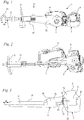
- Fig. 1 shows an implement 1.
- the implement 1 is a hand-operated implement, in the exemplary embodiment an olive shaker.
- the present invention can also be used for other work devices, both stationary and portable work devices.
- the working device can also be a pump, for example.
- the work device comprises a motor unit 2 which is used to drive a work unit 7.
- the working unit 7 is formed by a hook 51 which is driven back and forth in the direction of a double arrow 48 during operation.
- the hook 51 is held on a shaft 6 which is movably guided in a guide tube 47 of the working device 1.
- the guide tube 47 is designed in one piece with a gear housing 25.
- the transmission housing 25 is part of a transmission unit 3.
- a lateral handle 4 and a bow-shaped handle 5, which are held on the gear unit 3, are provided for guiding the implement 1.
- the side handle 4 and bow-type handle 5 are advantageously held on the gear unit 3 via vibration damping elements.
- the motor unit 2 comprises a motor housing 8.
- the motor housing 8 can be designed as a closed housing. However, it can also be provided that the motor housing 8 is designed to be partially open and / or is formed by a plurality of housing parts and / or covers.
- a drive motor 9 is arranged in the motor housing 8.
- the drive motor 9 is designed as an internal combustion engine in the exemplary embodiment.
- the drive motor 9 preferably has an in Fig. 3 starting device 64 shown schematically.
- a cooling air fan 10 is used to cool the drive motor 9.
- the drive motor 9 drives a drive shaft 22 to rotate about an axis of rotation 21.
- the cooling air fan 10 is driven via the drive shaft 22.
- the axis of rotation 21 corresponds to the axis of rotation of a fan wheel 16 of the cooling air blower 10.
- the drive shaft 22 is connected to a transmission 46 via a clutch 34, in the exemplary embodiment a centrifugal clutch.
- the gear 46 is arranged in the gear housing 25.
- Gear 46 is provided to convert the rotating movement, which is transmitted from the drive shaft 22 via the coupling 34 to the input shaft 63 of the gear 46, into a reciprocating movement of the shaft 6 along the double arrow 48.
- the gear housing 25 forms a very rigid structure.
- the gear housing 25 is preferably made of metal, in particular light metal, preferably magnesium.
- the gear housing 25 can be provided with stiffening struts to increase its rigidity. In Fig. 4 some of the stiffening struts 53 of the gear housing 25 are shown.
- Fig. 4 shows the drive motor 9, a fan housing 11 of the cooling air blower 10 as well as a connection structure 19 connected to the cooling air blower 10, which in the exemplary embodiment is at least partially formed by the gear housing 25.
- the drive motor 9 comprises a cylinder 24 and a crankcase 23.
- the cooling air fan 10 and the in Fig. 4 starting device 64 (not shown) Fig. 3 ) are arranged on opposite sides of the cylinder 24.
- a carburetor 54 is provided in the exemplary embodiment for supplying the fuel / air mixture to the drive motor 9. Any other type of fuel supply device can also be advantageous.
- the crankcase 23 is formed by a first crankcase component 44 and a second crankcase component 45. The parting plane between the crankcase components 44 and 45 runs in the exemplary embodiment parallel to one in Fig. 4 schematically entered cylinder longitudinal axis 55 of the cylinder 24.
- Fig. 5 shows a section through the cooling air fan 10.
- the fan housing 11 comprises a first side wall 13 and an opposing second side wall 14.
- the fan housing 11 is formed by a peripheral wall 15 which extends from the first side wall 13 to the second side wall 14.
- the first side wall 13, the second side wall 14 and the peripheral wall 15 delimit a fan space 12.
- Das Crankcase 23 is connected to the first side wall.
- the first crankcase component 44 is formed in one piece with the first side wall 13.
- a fan wheel 16 is arranged, which has a plurality of blades 17 for conveying cooling air.
- the fan wheel 16 is a radial fan, which generates cooling air in relation to the axis of rotation 21 of the fan wheel 16 ( Fig. 3 ) promotes radially outwards. Cooling air is sucked in through suction openings 56 which are formed in the first side wall 13 and of which in FIG Fig. 5 one is shown.
- connection structure 19 is fixed to the second side wall 14 by means of fastening screws 26, of which FIG Fig. 5 one is shown. It can also be provided that the second side wall 14 is formed in one piece with the connection structure 19 and is thereby connected to it. Another type of connection can also be provided.
- the connection structure 19 is connected to the drive motor 9 via the fan housing 11.
- the fan housing 11 is, in particular, a structure with a low mass and low rigidity.
- the mass of the fan housing 11 is advantageously less than 1.5 kg, in particular less than 1 kg.
- a mass of the fan housing 11 of 0.3 to 0.8 kg is provided.
- the connection structure 19 is advantageously a structure with a large mass.
- the connection structure 19 advantageously has a mass of at least 1.5 kg, in particular at least 3 kg, preferably more than 5 kg.
- a mass of the connection structure 19 of 7 kg to 9 kg is provided.
- the mass of the drive motor 9 is advantageously at least 1.5 kg, in particular at least 2 kg, preferably at least 3 kg.
- a mass of 4 kg to 7 kg is provided.
- the mass of the connection structure 19 is advantageously more than the mass of the drive motor 9.
- the mass of the connection structure 19 is advantageously 1.1 to 3 times, in particular 1.2 to 2.3 times, preferably 1.3 to 1.8 times the mass of the drive motor 9.
- the fan wheel 16 carries magnets 57 which serve to induce an ignition spark, as will be described in more detail below.
- connection structure 19 cannot follow these vibrations due to its high rigidity.
- the relative movements between drive motor 9 and connection structure 19 must therefore be absorbed by fan housing 11.
- the connecting strut 20 protrudes between the periphery 35 of the fan wheel 16 and the peripheral wall 15 through the fan space 12.
- the connecting strut 20 is screwed into a screw opening 30.
- the first side wall 13 is formed in one piece with the first crankcase component 44.
- the connecting strut 20 protrudes through the first side wall 13 into the screw opening 30 formed in the crankcase component 44.
- the connecting strut 20 rests on the second side wall 14 with a support collar 50.
- a fastening screw 42 is screwed into the connecting strut 20 through the second side wall 14.
- the second side wall 14 is formed on a housing part 27, namely a cover of the fan housing 11.
- the connection structure 19 is screwed to the housing part 27 by means of fastening screws 26.
- the housing part 27 is fixed to the first crankcase component 44 via fastening screws 28.
- the fastening screws 26 for fixing the connection structure 19 on the housing part 27 are screwed into fastening openings 29, as well Fig. 7 shows.
- the connecting strut 20 has an internal thread 39 for the fastening screw 42.
- the first side wall 13 and a part of the peripheral wall 15 are formed on the first crankcase component 44.
- the second side wall 14 and a further part of the peripheral wall 15 are formed on the housing part 27.
- the end faces of the first crankcase component 44 and housing part 27 lie against one another ( Fig. 6 ) and thus form the entire circumferential wall 15.
- a different configuration of the side walls 13 and 14 and the circumferential wall 15 can also be advantageous.
- the Figures 8 and 9 show the design of the connecting strut 20 in detail.
- the connecting strut 20 has an externally threaded section 37 with an external thread 43.
- the nominal diameter of the external thread 43 corresponds to the nominal diameter of the screw opening 30 ( Figures 6 and 7 ) matched in the crankcase component 44.
- the connecting strut 20 has the support collar 50 for support on the first side wall 13 and a support collar 58 for support on the second side wall 14.
- the support collar 58 has an attack contour 49, in the exemplary embodiment a hexagonal contour, on which a tool can attack the connecting strut 20 with the external thread 43 into the screw opening 30 of the first crankcase component 44 ( Figures 6 and 7 ) screw in.
- the internally threaded section 36 and a connecting section 38 extend between the support collars 50 and 58.
- the internally threaded section 36 has an internal thread 39 for the fastening screw 42 ( Figures 6 and 7 ) on.
- the internally threaded section 36 has an outer diameter e that is greater than the outer diameter f in the connecting section 38.
- the connecting strut 20 is preferably solid.
- the connecting strut 20 has a central axis 31.
- the central axis 31 has a distance c from the axis of rotation 21.
- the first crankcase component 44 has the fastening openings 59 for the fastening screws 28 ( Fig. 7 ).
- the fastening openings 59 each have a central axis 32 which is at a distance b from the axis of rotation 21. The distance b can be different for the Mounting openings 59 may be different. All fastening openings 59 are outside the circumferential wall 15.
- the distance b of at least one central axis 32 of a fastening opening 59 to the axis of rotation 21 is greater than the distance c of the central axis 31 of the connecting strut 20 to the axis of rotation 21.
- the distance b of all central axes 32 to the axis of rotation 21 is greater than the distance between the central axis 31 and the axis of rotation 21.
- Fig. 10 the flow direction 41 of the cooling air is also shown.
- the circumferential wall 15 is at a distance d from the axis of rotation 21, which increases in the direction of flow 41 at least in an angular range about the axis of rotation 21.
- an increase in the distance d is provided over a large part of the peripheral wall 15 in the flow direction 41.
- Fig. 11 shows the crankcase component 44 from the side remote from the fan chamber 12.
- the crankcase component 44 delimits a crankcase interior 52.
- the crankcase interior 52 is also separated from the second crankcase component 45 ( Fig. 4 ) limited.
- the position of the suction openings 56 is also shown.
- the fan wheel 16 has a diameter h.
- the distance d between the axis of rotation 21 and the peripheral wall 15 increases from a distance which is only slightly larger than half the diameter h of the fan wheel 16, to a distance d at the outlet opening 18 which is at least 1.2 times, preferably at least 1.3 times, in particular at least 1.4 times, half the diameter h, that is to say the radius of the fan wheel 14.
- a distance a is formed between the circumference 35 and the circumferential wall 15 which increases continuously in the flow direction 41 at least in a region of the circumference 35, preferably over a large part of the circumference 35.
- the cooling air leaves the fan space 12 through an outlet opening 18.
- the outlet opening is arranged adjacent to the cylinder 42 of the drive motor 9.
- An ignition module 60 is located on the cylinder 24 set. The ignition module 60 is arranged outside the fan space 12 in the exemplary embodiment. In the ignition module 60, the magnets 57 of the fan wheel 12 induce the energy for generating an ignition spark.
- the connecting strut 20 is arranged upstream of the outlet opening 18.
- the cooling air accordingly first flows past the connecting strut 20 and then through the outlet opening 18.
- the connecting strut 20 is arranged in the flow direction 41 in front of the outlet opening 18.
- the connecting strut 20 is at an angular distance ⁇ from the outlet opening 18 around the axis of rotation 21 of the fan wheel 16.
- the angular distance ⁇ is advantageously less than 90 °, in particular less than 60 °.
- An angle ⁇ of less than 45 ° is preferably provided.
- the angular distance ⁇ is less than 30 °, preferably less than 15 °.
- the distance a between the circumference 35 of the fan wheel 16 and the circumferential wall 15 in the circumferential angular region in which the connecting strut 20 is arranged is comparatively large.
- the distance a at the outlet opening 18 is advantageously at least 15 mm, in particular at least 20 mm.
- the distance a at the outlet opening 18 is advantageously at least 10%, in particular at least 15%, preferably at least 20% of the diameter h of the fan wheel 16.
- the fan space 12 has a width m on the connecting strut 15, which in Fig. 6 is registered.
- the width m is significantly smaller than the diameter h of the fan wheel 16 ( Fig. 12 ).
- the width m is advantageously less than half the diameter h of the fan wheel 16, in particular less than 30% of the diameter h of the fan wheel 16.
- the diameter h of the fan wheel 16 is advantageously 80 cm to 170 cm, in particular 90 cm to 150 cm.
- the peripheral wall 15 is offset radially outside the connecting strut 20 to the outside.
- Fig. 12 is the spiral course of the peripheral wall 15 shown schematically with a dashed line 61.
- the peripheral wall 15 is offset radially outward by an offset k to the axis of rotation 21.
- the offset k preferably compensates for the reduction in the flow cross section through the connecting strut 20 at least partially, preferably completely.
- the offset k is advantageously at least 3 mm, in particular at least 5 mm.
- the offset k is in particular less than 20 mm, preferably less than 15 mm.
- the offset k is advantageously from 3% to 20%, in particular from 5% to 15% of the diameter h of the fan wheel 14.
- the circumferential wall 15 is over at least part of its width m measured parallel to the axis of rotation, preferably over its entire width m, relative to the axis of rotation 21 shifted radially outward.
- Fig. 13 shows the position of the fastening screws 26 with which the connection structure 19 is fixed to the second side wall 14.
- the fastening screws 26 each have a central axis 33.
- the center axis 33 is at a distance g from the axis of rotation 21, which in FIG Fig. 13 for one of the fastening screws 26 is shown.
- the fastening screws 26 can have different distances g from the axis of rotation 21. However, the same distance g for some or all of the fastening screws 26 can also be advantageous.
- the position of the central axis 31 of the connecting strut 20 is shown schematically in a projection in the direction of the axis of rotation 21.
- the distance c between the central axis 31 of the connecting strut 20 and the axis of rotation 21 is greater than the distance g of the central axis 33 of the fastening screw 26.
- all central axes 33 of the fastening screws 26 are located in a projection in the viewing direction of the axis of rotation 21 within the Circumferential wall 15, i.e. between the axis of rotation 21 and the circumferential wall 15.
- the distance g of at least one central axis 33 is advantageously smaller than half the diameter h of the fan wheel 16.
- the distance g of at least one, in particular all of the central axes 33, is significantly smaller in the exemplary embodiment than the distance b of one, in particular all of the central axes 32 of the fastening screws 28 with which the housing part 27 is fixed to the first crankcase component 44.
- Fig. 14 shows an alternative embodiment for a connecting strut 20 '.
- the structure of the connecting strut 20 ' corresponds to the structure of the connecting strut 20 in the area arranged between the side walls 13 and 14.
- the connecting strut 20' is, however, formed in one piece with the crankcase component 44. It can be provided that the connecting strut 20 ′ is also formed in one piece with the second side wall 14.
- the connecting strut 20 ' is preferably connected in one piece to one of the side walls 13, 14 and fixed, in particular screwed, to the other of the side walls 13, 14.
- the connecting strut 20 ′ is preferably formed in one piece on the first side wall 13 and the crankcase component 44 and is screwed tightly to the second side wall 14 via a fastening screw 42, as in FIG Fig. 14 shown.
Landscapes
- Engineering & Computer Science (AREA)
- Mechanical Engineering (AREA)
- General Engineering & Computer Science (AREA)
- Chemical & Material Sciences (AREA)
- Combustion & Propulsion (AREA)
- Structures Of Non-Positive Displacement Pumps (AREA)
- Motor Or Generator Cooling System (AREA)
- Cooling Or The Like Of Electrical Apparatus (AREA)
- Percussive Tools And Related Accessories (AREA)
Abstract
Description
- Die Erfindung betrifft ein Arbeitsgerät der im Oberbegriff des Anspruchs 1 angegebenen Gattung.
- Aus der
DE 100 21 707 A1 ist ein Arbeitsgerät, nämlich ein Freischneider, mit einem Antriebsmotor bekannt. Der Antriebsmotor treibt eine Arbeitseinheit, nämlich ein Messerblatt, rotierend an. Zur Kühlung des Antriebsmotors dient ein von dem Antriebsmotor angetriebenes Lüfterrad. Am Antriebsmotor ist eine Seitenwand des Lüftergehäuses gehalten. An der gegenüberliegenden Seitenwand des Lüftergehäuses schließt eine Anschlussstruktur an, die das Führungsrohr und die Arbeitseinheit des Arbeitsgeräts umfasst. Das Lüftergehäuse liegt demnach in axialer Richtung zwischen Antriebsmotor und Arbeitseinheit. Es hat sich gezeigt, dass bei Anschluss einer anderen, insbesondere einer schwereren und/oder steiferen Anschlussstruktur Schäden oder vorzeitiger Verschleiß am Lüftergehäuse auftreten können. - Der Erfindung liegt die Aufgabe zugrunde, ein Arbeitsgerät der gattungsgemäßen Art zu schaffen, das eine hohe Lebensdauer aufweist.
- Diese Aufgabe wird durch ein Arbeitsgerät mit den Merkmalen des Anspruchs 1 gelöst.
- Der Antriebsmotor bildet bei Arbeitsgeräten üblicherweise eine steife Struktur. Der Lüfterraum besitzt einen vergleichsweise großen Durchmesser, um eine ausreichend große Menge Kühlluft fördern zu können. Dadurch ist die aus den beiden Seitenwänden und der Umfangswand des Lüfterraums gebildete Struktur vergleichsweise weich und verformbar. Bei Freischneidern ist das Führungsrohr als langes, vergleichsweise dünnes Rohr gebildet. Daher bildet auch das Führungsrohr eine weiche Struktur. Im Betrieb vom Motor erzeugte Schwingungen können daher bei einem Freischneider zu einem großen Teil durch das Führungsrohr aufgenommen werden, das zu entsprechenden Schwingungen angeregt wird.
- Es hat sich nun gezeigt, dass die Belastungen, die auf das Lüftergehäuse wirken, deutlich größer werden, wenn anstatt des Führungsrohrs und der Arbeitseinheit eine Anschlussstruktur mit großer Trägheit an der zweiten Seitenwand anschließt. Eine Anschlussstruktur mit großer Trägheit kann bei Schwingungen des Antriebsmotors nicht oder nicht in ausreichendem Maß mitbewegt werden. Die Relativbewegungen zwischen Antriebsmotor und der Anschlussstruktur müssen daher vom Lüftergehäuse aufgenommen werden, das hierzu hochfrequent verformt werden kann. Es hat sich gezeigt, dass diese Verformung des Lüftergehäuses zu vorzeitigen Schäden am Lüftergehäuse führen kann. Unter Anschlussstruktur werden vorliegend alle Elemente verstanden, die an der zweiten Seitenwand anschließen. Die Anschlussstruktur umfasst dabei auch die Arbeitseinheit, beispielsweise ein Werkzeug des Arbeitsgeräts.
- Erfindungsgemäß ist eine Verbindungsstrebe vorgesehen, die zwischen dem Umfang des Lüfterrads und der Umfangswand durch den Lüfterraum ragt und die erste Seitenwand mit der zweiten Seitenwand verbindet. Dadurch, dass die Verbindungsstrebe zwischen dem Umfang des Lüfterrads und der Umfangswand, also radial innerhalb der Umfangswand, angeordnet ist, ist der Abstand der Verbindungsstrebe zur Drehachse des Lüfterrads verglichen mit außerhalb des Lüfterraums angeordneten Versteifungselementen vergleichsweise gering. Dadurch wird für eine gewünschte Versteifung des Lüftergehäuses eine Verbindungsstrebe mit vergleichsweise geringem Querschnitt benötigt. Bereits mit geringer Zunahme des Gesamtgewichts des Arbeitsgeräts kann eine ganz erhebliche Erhöhung der Stabilität des Arbeitsgeräts erreicht werden. Eine Versteifung beispielsweise an der Außenseite der Umfangswand des Lüftergehäuses, die aufgrund des großen Abstands zur Drehachse des Lüfterrads sehr massiv ausgebildet sein müsste und daher zu einer erheblichen Gewichtserhöhung des Arbeitsgeräts führen würde, kann durch die erfindungsgemäße Verbindungsstrebe vermieden werden.
- Die Anschlussstruktur ist vorteilhaft eine vergleichsweise schwere Struktur. Das Gewicht der Anschlussstruktur beträgt vorteilhaft mindestens mehr als 1,5 kg, insbesondere mehr als 2 kg, vorzugsweise mehr als 3 kg.
- Bezogen auf die Strömungsrichtung der geförderten Kühlluft ist die Verbindungsstrebe vorteilhaft stromauf der Austrittsöffnung angeordnet. Die Verbindungsstrebe besitzt zur Austrittsöffnung vorteilhaft einen Winkelabstand von weniger als 90° um die Drehachse des Lüfterrads. Der Abstand der Umfangswand zum Umfang des Lüfterrads nimmt in Strömungsrichtung der geförderten Kühlluft zumindest in einem Abschnitt des Lüfterraums zu. Bevorzugt verläuft die Umfangswand im Wesentlichen spiralförmig um die Drehachse. Durch die Anordnung der Verbindungsstrebe vergleichsweise nah an der Austrittsöffnung wird die Verbindungsstrebe in einem Bereich angeordnet, in dem ohnehin ein vergleichsweise großer Strömungsquerschnitt vorhanden ist. Dadurch ist der Einfluss der Verbindungsstrebe auf die Menge der geförderten Kühlluft vergleichsweise gering. Da im Bereich der Austrittsöffnung auch der Abstand zwischen Drehachse und Umfangswand am größten ist, wird durch eine in diesem Umfangsbereich angebrachte Verbindungsstrebe eine größtmögliche Entlastung der Umfangswand erzielt.
- Eine einfache Gestaltung und Montage ergibt sich, wenn die Verbindungsstrebe als separates Bauteil ausgebildet ist und mindestens einen Gewindeabschnitt zur Verbindung mit einem angrenzenden Bauteil aufweist. Die Verbindungsstrebe weist insbesondere einen Innengewindeabschnitt mit einem Innengewinde auf, in das eine Befestigungsschraube eingeschraubt ist. Dadurch kann ein angrenzendes Bauteil auf einfache Weise an der Verbindungsstrebe befestigt werden. Die Verbindungsstrebe weist vorteilhaft einen Verbindungsabschnitt auf, dessen Außendurchmesser kleiner als ein Außendurchmesser des Innengewindeabschnitts ist. Der Innengewindeabschnitt und der Verbindungsabschnitt sind dabei mindestens teilweise, insbesondere vollständig in dem Lüfterraum angeordnet. In dem Verbindungsabschnitt ist der Außendurchmesser der Verbindungsstrebe reduziert, um einen möglichst große Strömungsquerschnitt bereitzustellen. Im Bereich des Innengewindeabschnitts wird vorteilhaft ein konstruktiv vorgegebener Mindestaußendurchmesser bereitgestellt, um eine ausreichende Festigkeit für das Innengewinde sicherzustellen.
- In vorteilhafter Gestaltung weist die Verbindungsstrebe einen Außengewindeabschnitt mit einem Außengewinde auf, das in eine Schrauböffnung in einer Seitenwand eingeschraubt ist. Mit dem Außengewindeabschnitt kann die Verbindungsstrebe an einer der Seitenwände verschraubt werden. Nach Montage der anderen Seitenwand kann über eine Befestigungsschraube, die von außen in die Verbindungsstrebe eingeschraubt wird, die weitere Seitenwand an der Verbindungsstrebe fixiert werden. Die Befestigungsschraube kann dabei auch zur Anbindung der Anschlussstruktur genutzt werden. Dadurch ergibt sich ein einfacher Aufbau.
- In vorteilhafter alternativer Gestaltung ist die Verbindungsstrebe mit mindestens einer Seitenwand einteilig ausgebildet. An der gegenüberliegenden Seitenwand kann die Verbindungsstrebe beispielsweise mittels einer Schraube oder dgl. fixiert werden. Die Verbindungsstrebe ist an beiden Seitenwänden zur Übertragung von im Betrieb entstehenden Kräften fest fixiert.
- Der Antriebsmotor ist insbesondere ein Verbrennungsmotor mit einem Kurbelgehäuse, das aus mindestens einem Kurbelgehäusebauteil gebildet ist. Vorteilhaft ist die Verbindungsstrebe an dem Kurbelgehäusebauteil festgelegt. Das Kurbelgehäusebauteil kann als tragende Struktur mit hoher Trägheit ausgebildet sein. Durch Anbindung der Verbindungsstrebe an dem Kurbelgehäusebauteil ergibt sich eine feste und stabile Anbindung der Verbindungsstrebe. Vorzugsweise ist die erste Seitenwand unmittelbar und die zweite Seitenwand über die Verbindungsstrebe an dem Kurbelgehäusebauteil festgelegt. In besonders vorteilhafter Gestaltung ist die erste Seitenwand an dem Kurbelgehäusebauteil des Antriebsmotors angeformt. Dadurch ergibt sich ein einfacher Aufbau mit wenigen Einzelteilen.
- Es kann vorgesehen sein, dass die Anschlussstruktur ein Getriebegehäuse umfasst, in dem ein Getriebe angeordnet ist. Über das Getriebe ist die Antriebseinheit angetrieben. Das Arbeitsgerät kann beispielsweise ein Erntegerät wie ein Olivenschüttler oder dgl. sein. Vorteilhaft wandelt das Getriebe die rotierende Antriebsbewegung des Antriebsmotors in eine hin- und hergehende Bewegung um. Die Antriebseinheit ist insbesondere ein Werkzeug des Arbeitsgeräts, beispielsweise ein Haken eines Olivenschüttlers, mit dem zu schüttelnde Äste gegriffen werden können. Es kann auch vorgesehen sein, dass das Arbeitsgerät eine Pumpe ist und die Arbeitseinheit des Arbeitsgeräts die Pumpeneinheit, die von dem Antriebsmotor angetrieben ist. Auch eine andere Anschlussstruktur mit einer anderen Arbeitseinheit kann vorgesehen sein.
- Vorteilhaft ist die Anschlussstruktur über mindestens eine Befestigungsschraube an der zweiten Seitenwand festgeschraubt. Der Abstand der Mittelachse der Befestigungsschraube zur Drehachse des Lüfterrads ist dabei vorteilhaft kleiner als der halbe Durchmesser des Lüfterrads. Die Mittelachse der Befestigungsschraube liegt demnach so, dass die Befestigungsschraube sich in Blickrichtung der Drehachse des Lüfterrads mit dem Lüfterrad überschneidet. Dadurch kann die Befestigungsschraube nicht unmittelbar an der ersten Seitenwand oder einer dahinter liegenden Struktur eingeschraubt werden. Stattdessen müssen die zwischen Motoreinheit und Arbeitseinheit wirkenden Kräfte über die Umfangswand des dazwischenliegenden Lüftergehäuses übertragen werden. Durch den verhältnismäßig großen Abstand der Umfangswand zur Drehachse, also insbesondere zur neutralen Faser, wirken hohe Momente.
- Dadurch, dass der Abstand der Mittelachse der Befestigungsschraube vergleichsweise gering ist, lässt sich ein kompakter Aufbau der Anschlussstruktur erreichen. Dadurch werden die Bedienung des Arbeitsgeräts und das Arbeiten mit dem Arbeitsgerät vereinfacht. In alternativer Gestaltung kann vorgesehen sein, dass zumindest ein Teil der Anschlussstruktur mit einem Teil des Lüftergehäuses, insbesondere zumindest mit einem Teil der zweiten Seitenwand einteilig ausgebildet ist. Vorzugsweise ist zumindest ein Teil der Anschlussstruktur mit der zweiten Seitenwand und besonders bevorzugt ergänzend mit einem Teil der Umfangswand einteilig ausgebildet.
- Die Umfangswand ist in einem Bereich, der radial außerhalb der Verbindungsstrebe liegt, gegenüber einem spiralförmigen Verlauf vorteilhaft zumindest über einen Teil ihrer Breite um mindestens die Hälfte des kleinsten Durchmessers der Verbindungsstrebe radial nach außen verschoben. Die Verringerung des Strömungsquerschnitts, die durch die Verbindungsstrebe entsteht, kann durch die Verschiebung der Umfangswand radial nach außen zumindest teilweise kompensiert werden. Dadurch wird trotz der zwischen Umfangswand und Umfang des Lüfterrads angeordneten Verbindungsstrebe ein ausreichender Durchsatz von Kühlluft erreicht. Der Ausdruck "radial" bezieht sich dabei auf die radiale Richtung zur Drehachse des Lüfterrads.
- Die vorliegende Erfindung ist insbesondere dann vorteilhaft, wenn die Anschlussstruktur ein Gehäuse umfasst, das aus Metall gebildet ist. Dadurch weist die Anschlussstruktur eine hohe Steifigkeit bzw. Trägheit auf. Das Metall ist insbesondere Leichtmetall, vorzugsweise Magnesium. Auch eine andere Gestaltung des Gehäuses der Anschlussstruktur kann jedoch vorteilhaft sein.
- Ausführungsbeispiele der Erfindung werden im Folgenden anhand der Zeichnung erläutert. Es zeigen:
- Fig. 1
- eine schematische Seitenansicht eines Arbeitsgeräts,
- Fig. 2
- eine schematische Draufsicht auf einen Teil des Arbeitsgeräts aus
Fig. 1 in Richtung des Pfeils II inFig. 1 , - Fig. 3
- eine schematische Darstellung des Antriebsstrangs des Arbeitsgeräts in einer Blickrichtung entsprechend
Fig. 2 , - Fig. 4
- eine ausschnittsweise Darstellung von Antriebsmotor, Lüftergehäuse und Anschlussstruktur des Arbeitsgeräts,
- Fig. 5
- eine ausschnittsweise Schnittdarstellung durch das Lüftergehäuse entlang der Linie V-V in
Fig. 13 , - Fig. 6
- eine ausschnittsweise Schnittdarstellung durch das Lüftergehäuse, den Antriebsmotor und die Anschlussstruktur entlang der Linie VI-VI in
Fig. 12 , - Fig. 7
- eine Explosionsdarstellung des Kühlluftgebläses,
- Fig. 8
- eine perspektivische Darstellung einer Verbindungsstrebe,
- Fig. 9
- eine Seitenansicht der Verbindungsstrebe aus
Fig. 8 , - Fig. 10 und 11
- Seitenansichten eines Kurbelgehäusebauteils,
- Fig. 12
- eine Schnittdarstellung durch das Lüftergehäuse entlang der Linie XII-XII in
Fig. 6 , - Fig. 13
- einen Schnitt entlang der Linie XIII-XIII in
Fig. 6 , - Fig. 14
- eine ausschnittsweise Schnittdarstellung in einem Schnitt entsprechend
Fig. 6 für ein weiteres Ausführungsbeispiel. -
Fig. 1 zeigt ein Arbeitsgerät 1. Das Arbeitsgerät 1 ist ein handgeführtes Arbeitsgerät, im Ausführungsbeispiel ein Olivenschüttler. Die vorliegende Erfindung kann auch für andere Arbeitsgeräte, und zwar sowohl für stationäre als auch für tragbare Arbeitsgeräte zum Einsatz kommen. Das Arbeitsgerät kann beispielsweise auch eine Pumpe sein. Das Arbeitsgerät umfasst eine Motoreinheit 2, die zum Antrieb einer Arbeitseinheit 7 dient. Im Ausführungsbeispiel ist die Arbeitseinheit 7 durch einen Haken 51 gebildet, der in Richtung eines Doppelpfeils 48 im Betrieb hin- und hergehend angetrieben ist. Hierzu ist der Haken 51 an einem Schaft 6 gehalten, der in einem Führungsrohr 47 des Arbeitsgeräts 1 beweglich geführt ist. Im Ausführungsbeispiel ist das Führungsrohr 47 einteilig mit einem Getriebegehäuse 25 ausgebildet. Das Getriebegehäuse 25 ist Teil einer Getriebeeinheit 3. - Wie
Fig. 1 auch zeigt, sind zum Führen des Arbeitsgeräts 1 ein seitlicher Handgriff 4 sowie ein Bügelgriff 5 vorgesehen, die an der Getriebeeinheit 3 gehalten sind. Vorteilhaft sind seitlicher Handgriff 4 und Bügelgriff 5 über Schwingungsdämpfungselemente an der Getriebeeinheit 3 gehalten. - Wie die
Figuren 1 bis 3 zeigen, umfasst die Motoreinheit 2 ein Motorgehäuse 8. Das Motorgehäuse 8 kann als geschlossenes Gehäuse ausgebildet sein. Es kann jedoch auch vorgesehen sein, dass das Motorgehäuse 8 teilweise offen ausgebildet und/oder durch mehrere Gehäuseteile und/oder Abdeckungen gebildet ist. WieFig. 3 zeigt, ist im Motorgehäuse 8 ein Antriebsmotor 9 angeordnet. Der Antriebsmotor 9 ist im Ausführungsbeispiel als Verbrennungsmotor ausgebildet. Der Antriebsmotor 9 weist vorzugsweise eine inFig. 3 schematisch dargestellte Anwerfvorrichtung 64 auf. Zur Kühlung des Antriebsmotors 9 dient ein Kühlluftgebläse 10. Der Antriebsmotor 9 treibt eine Antriebswelle 22 um eine Drehachse 21 rotierend an. Über die Antriebswelle 22 ist das Kühlluftgebläse 10 angetrieben. Die Drehachse 21 entspricht der Drehachse eines Lüfterrads 16 des Kühlluftgebläses 10. Die Antriebswelle 22 ist über eine Kupplung 34, im Ausführungsbeispiel eine Fliehkraftkupplung, mit einem Getriebe 46 verbunden. Das Getriebe 46 ist im Getriebegehäuse 25 angeordnet. Im Ausführungsbeispiel ist das Getriebe 46 dazu vorgesehen, die rotierende Bewegung, die von der Antriebswelle 22 über die Kupplung 34 auf die Eingangswelle 63 des Getriebes 46 übertragen wird, in eine hin- und hergehende Bewegung des Schafts 6 entlang des Doppelpfeils 48 umzuwandeln. Das Getriebegehäuse 25 bildet eine sehr starre Struktur. Das Getriebegehäuse 25 besteht vorzugsweise aus Metall, insbesondere aus Leichtmetall, vorzugsweise aus Magnesium. Das Getriebegehäuse 25 kann zur Erhöhung seiner Steifigkeit mit Versteifungsstreben versehen sein. InFig. 4 sind einige der Versteifungsstreben 53 des Getriebegehäuses 25 gezeigt. -
Fig. 4 zeigt den Antriebsmotor 9, ein Lüftergehäuse 11 des Kühlluftgebläses 10 sowie eine am Kühlluftgebläse 10 anschließende Anschlussstruktur 19, die im Ausführungsbeispiel zumindest teilweise durch das Getriebegehäuse 25 gebildet ist. - Der Antriebsmotor 9 umfasst einen Zylinder 24 sowie ein Kurbelgehäuse 23. Das Kühlluftgebläse 10 und die in
Fig. 4 nicht dargestellte Anwerfvorrichtung 64 (Fig. 3 ) sind auf gegenüberliegenden Seiten des Zylinders 24 angeordnet. Zur Zufuhr von Kraftstoff/Luft-Gemisch zum Antriebsmotor 9 ist im Ausführungsbeispiel ein Vergaser 54 vorgesehen. Auch jede andere Art von Kraftstoffzuführeinrichtung kann vorteilhaft sein. Das Kurbelgehäuse 23 ist durch ein erstes Kurbelgehäusebauteil 44 und ein zweites Kurbelgehäusebauteil 45 gebildet. Die Trennebene zwischen den Kurbelgehäusebauteilen 44 und 45 verläuft im Ausführungsbeispiel parallel zu einer inFig. 4 schematisch eingetragenen Zylinderlängsachse 55 des Zylinders 24. -
Fig. 5 zeigt einen Schnitt durch das Kühlluftgebläse 10. Wie der inFig. 13 angedeutete Schnittverlauf zeigt, verläuft der inFig. 5 dargestellte Schnitt nicht durch die Antriebswelle 22, sondern hierzu versetzt. WieFig. 5 zeigt, umfasst das Lüftergehäuse 11 eine erste Seitenwand 13 sowie eine gegenüberliegende zweite Seitenwand 14. Am Umfang ist das Lüftergehäuse 11 von einer Umfangswand 15 gebildet, die sich von der ersten Seitenwand 13 zur zweiten Seitenwand 14 erstreckt. Die erste Seitenwand 13, die zweite Seitenwand 14 und die Umfangswand 15 begrenzen einen Lüfterraum 12. Das Kurbelgehäuse 23 ist mit der ersten Seitenwand verbunden. Im Ausführungsbeispiel ist das erste Kurbelgehäusebauteil 44 einteilig mit der ersten Seitenwand 13 ausgebildet. Im Lüfterraum 12 ist ein Lüfterrad 16 angeordnet, das eine Vielzahl von Schaufeln 17 zur Förderung von Kühlluft aufweist. Das Lüfterrad 16 ist ein Radialgebläse, das Kühlluft bezogen auf die Drehachse 21 des Lüfterrads 16 (Fig. 3 ) radial nach außen fördert. Die Ansaugung von Kühlluft erfolgt durch Ansaugöffnungen 56, die in der ersten Seitenwand 13 ausgebildet sind und von denen inFig. 5 eine dargestellt ist. - An der zweiten Seitenwand 14 ist die Anschlussstruktur 19 über Befestigungsschrauben 26 festgelegt, von denen in
Fig. 5 eine dargestellt ist. Es kann auch vorgesehen sein, dass die zweite Seitenwand 14 einteilig mit der Anschlussstruktur 19 ausgebildet und dadurch mit dieser verbunden ist. Auch eine andere Art der Verbindung kann vorgesehen sein. - Über das Lüftergehäuse 11 ist die Anschlussstruktur 19 mit dem Antriebsmotor 9 verbunden. Das Lüftergehäuse 11 ist insbesondere eine Struktur mit geringer Masse und geringer Steifigkeit. Die Masse des Lüftergehäuses 11 beträgt vorteilhaft weniger als 1,5 kg, insbesondere weniger als 1 kg. Im Ausführungsbeispiel ist eine Masse des Lüftergehäuses 11 von 0,3 bis 0,8 kg vorgesehen. Die Anschlussstruktur 19 ist vorteilhaft eine Struktur mit großer Masse. Die Anschlussstruktur 19 weist vorteilhaft eine Masse von mindestens 1,5 kg, insbesondere mindestens 3 kg, vorzugsweise mehr als 5 kg auf. Im Ausführungsbeispiel ist eine Masse der Anschlussstruktur 19 von 7 kg bis 9 kg vorgesehen. Die Masse des Antriebsmotors 9 beträgt vorteilhaft mindestens 1,5 kg, insbesondere mindestens 2 kg, vorzugsweise mindestens 3 kg. Im Ausführungsbeispiel ist eine Masse von 4 kg bis 7 kg vorgesehen. Mindestens eine Struktur, insbesondere beide Strukturen, die an eine, insbesondere an beide Seitenwände 13 und 14 des Lüftergehäuses 11 anschließen, weisen vorteilhaft jeweils eine Masse auf, die mindestens das 2fache, vorzugsweise mindestens das 4fache, bevorzugt mindestens das 6fache der Masse des Lüftergehäuses 11 beträgt. Die Masse der Anschlussstruktur 19 beträgt vorteilhaft mehr als die Masse des Antriebsmotors 9. Die Masse der Anschlussstruktur 19 beträgt vorteilhaft das 1,1fache bis 3fache, insbesondere das 1,2fache bis 2,3fache, vorzugsweise das 1,3fache bis 1,8fache der Masse des Antriebsmotors 9.
- Im Ausführungsbeispiel trägt das Lüfterrad 16 Magnete 57, die zur Induzierung eines Zündfunkens dienen, wie im Folgenden noch näher beschrieben wird.
- Im Betrieb werden vom Antriebsmotor 9 aufgrund der hin- und hergehenden Bewegung eines im Zylinder 24 geführten Kolbens hochfrequente Schwingungen erzeugt. Diesen Schwingungen kann die Anschlussstruktur 19 aufgrund ihrer hohen Steifigkeit nicht folgen. Die Relativbewegungen zwischen Antriebsmotor 9 und Anschlussstruktur 19 müssen daher vom Lüftergehäuse 11 aufgenommen werden. Um eine übermäßige mechanische Belastung des Lüftergehäuses 11, insbesondere der Umfangswand 15 zu vermeiden, ist vorgesehen, die erste Seitenwand 13 und die zweite Seitenwand 14 über eine in
Fig. 6 gezeigte Verbindungsstrebe 20 mechanisch miteinander zu verbinden. WieFig. 6 zeigt, ragt die Verbindungsstrebe 20 zwischen dem Umfang 35 des Lüfterrads 16 und der Umfangswand 15 durch den Lüfterraum 12. Die Verbindungsstrebe 20 ist in eine Schrauböffnung 30 eingeschraubt. Die erste Seitenwand 13 ist einteilig mit dem ersten Kurbelgehäusebauteil 44 ausgebildet. Die Verbindungsstrebe 20 ragt durch die erste Seitenwand 13 in die im Kurbelgehäusebauteil 44 ausgebildete Schrauböffnung 30. An der zweiten Seitenwand 14 liegt die Verbindungsstrebe 20 mit einem Abstützbund 50 an. Durch die zweite Seitenwand 14 ist eine Befestigungsschraube 42 in die Verbindungsstrebe 20 eingeschraubt. Die zweite Seitenwand 14 ist an einem Gehäuseteil 27, nämlich einem Deckel des Lüftergehäuses 11 ausgebildet. An dem Gehäuseteil 27 ist die Anschlussstruktur 19 über Befestigungsschrauben 26 festgeschraubt. WieFig. 7 zeigt, ist das Gehäuseteil 27 über Befestigungsschrauben 28 am ersten Kurbelgehäusebauteil 44 fixiert. Die Befestigungsschrauben 26 zur Fixierung der Anschlussstruktur 19 am Gehäuseteil 27 sind in Befestigungsöffnungen 29 eingeschraubt, wie auchFig. 7 zeigt. Für die Befestigungsschraube 42 weist die Verbindungsstrebe 20 ein Innengewinde 39 auf. - Wie
Fig. 7 zeigt, sind die erste Seitenwand 13 und ein Teil der Umfangswand 15 am ersten Kurbelgehäusebauteil 44 angeformt. Am Gehäuseteil 27 sind die zweite Seitenwand 14 sowie ein weiterer Teil der Umfangswand 15 ausgebildet. Die Stirnseiten von erstem Kurbelgehäusebauteil 44 und Gehäuseteil 27 liegen aneinander an (Fig. 6 ) und bilden so die gesamte Umfangswand 15. Auch eine andere Ausbildung der Seitenwände 13 und 14 sowie der Umfangswand 15 kann vorteilhaft sein. - Die
Figuren 8 und 9 zeigen die Gestaltung der Verbindungsstrebe 20 im Einzelnen. An einem Ende weist die Verbindungsstrebe 20 einen Außengewindeabschnitt 37 mit einem Außengewinde 43 auf. Der Nenndurchmesser des Außengewindes 43 ist auf den Nenndurchmesser der Schrauböffnung 30 (Figuren 6 und 7 ) im Kurbelgehäusebauteil 44 abgestimmt. Die Verbindungsstrebe 20 besitzt den Abstützbund 50 zur Abstützung an der ersten Seitenwand 13 sowie einen Abstützbund 58 zur Abstützung an der zweiten Seitenwand 14. Der Abstützbund 58 weist eine Angriffskontur 49, im Ausführungsbeispiel eine Sechskantkontur auf, an der ein Werkzeug angreifen kann, um die Verbindungsstrebe 20 mit dem Außengewinde 43 in die Schrauböffnung 30 des ersten Kurbelgehäusebauteils 44 (Figuren 6 und 7 ) einzuschrauben. Zwischen den Abstützbünden 50 und 58 erstrecken sich ein Innengewindeabschnitt 36 sowie ein Verbindungsabschnitt 38. Der Innengewindeabschnitt 36 weist ein Innengewinde 39 für die Befestigungsschraube 42 (Figuren 6 und 7 ) auf. Der Innengewindeabschnitt 36 weist einen Außendurchmesser e auf, der größer als der Außendurchmesser f im Verbindungsabschnitt 38 ist. Im Verbindungsabschnitt 38 ist die Verbindungsstrebe 20 vorzugsweise massiv ausgebildet. - Wie
Fig. 9 zeigt, weist die Verbindungsstrebe 20 eine Mittelachse 31 auf. WieFig. 10 zeigt, besitzt die Mittelachse 31 zur Drehachse 21 einen Abstand c. Das erste Kurbelgehäusebauteil 44 weist die Befestigungsöffnungen 59 für die Befestigungsschrauben 28 auf (Fig. 7 ). Die Befestigungsöffnungen 59 weisen jeweils eine Mittelachse 32 auf, die zur Drehachse 21 einen Abstand b aufweist. Der Abstand b kann für die unterschiedlichen Befestigungsöffnungen 59 unterschiedlich sein. Alle Befestigungsöffnungen 59 liegen außerhalb der Umfangswand 15. Der Abstand b mindestens einer Mittelachse 32 einer Befestigungsöffnung 59 zur Drehachse 21 ist größer als der Abstand c der Mittelachse 31 der Verbindungsstrebe 20 zur Drehachse 21. Bevorzugt ist der Abstand b aller Mittelachsen 32 zur Drehachse 21 größer als der Abstand der Mittelachse 31 zur Drehachse 21. - In
Fig. 10 ist auch die Strömungsrichtung 41 der Kühlluft eingezeichnet. Die Umfangswand 15 weist zur Drehachse 21 einen Abstand d auf, der in Strömungsrichtung 41 zumindest in einem Winkelbereich um die Drehachse 21 zunimmt. Im Ausführungsbeispiel ist über einen Großteil der Umfangswand 15 in Strömungsrichtung 41 eine Vergrößerung des Abstands d vorgesehen. -
Fig. 11 zeigt das Kurbelgehäusebauteil 44 von der dem Lüfterraum 12 entfernt liegenden Seite. Das Kurbelgehäusebauteil 44 begrenzt einen Kurbelgehäuseinnenraum 52. Der Kurbelgehäuseinnenraum 52 ist auch vom zweiten Kurbelgehäusebauteil 45 (Fig. 4 ) begrenzt. In denFiguren 10 und 11 ist auch die Lage der Ansaugöffnungen 56 gezeigt. - Wie
Fig. 12 zeigt, besitzt das Lüfterrad 16 einen Durchmesser h. Der Abstand d zwischen der Drehachse 21 und der Umfangswand 15 vergrößert sich von einem Abstand, der nur geringfügig größer als der halbe Durchmesser h des Lüfterrads 16 ist, bis auf einen Abstand d an der Austrittsöffnung 18, der mindestens das 1,2fache, vorzugsweise mindestens das 1,3fache, insbesondere mindestens das 1,4fache des halben Durchmessers h, also des Radius des Lüfterrads 14, beträgt. Zwischen dem Umfang 35 und der Umfangswand 15 ist ein Abstand a gebildet, der sich in Strömungsrichtung 41 zumindest in einem Bereich des Umfangs 35, bevorzugt über einen Großteil des Umfangs 35 kontinuierlich vergrößert. Die Kühlluft verlässt den Lüfterraum 12 durch eine Austrittsöffnung 18. Die Austrittsöffnung ist im Ausführungsbeispiel benachbart zum Zylinder 42 des Antriebsmotors 9 angeordnet. Am Zylinder 24 ist ein Zündmodul 60 festgelegt. Das Zündmodul 60 ist im Ausführungsbeispiel außerhalb des Lüfterraums 12 angeordnet. Im Zündmodul 60 induzieren die Magnete 57 des Lüfterrads 12 die Energie zur Erzeugung eines Zündfunkens. - Bezogen auf die Strömungsrichtung 41 ist die Verbindungsstrebe 20 stromauf der Austrittsöffnung 18 angeordnet. Die Kühlluft strömt demnach zunächst an der Verbindungsstrebe 20 vorbei und dann durch die Austrittsöffnung 18. Die Verbindungsstrebe 20 ist in Strömungsrichtung 41 vor der Austrittsöffnung 18 angeordnet. Die Verbindungsstrebe 20 weist zur Austrittsöffnung 18 einen Winkelabstand α um die Drehachse 21 des Lüfterrads 16 auf. Der Winkelabstand α beträgt vorteilhaft weniger als 90°, insbesondere weniger als 60°. Bevorzugt ist ein Winkel α von weniger als 45° vorgesehen. Im Ausführungsbeispiel beträgt der Winkelabstand α weniger als 30°, vorzugsweise weniger als 15°. Dadurch ist der Abstand a zwischen Umfang 35 des Lüfterrads 16 und Umfangswand 15 in dem Umfangswinkelbereich, in dem die Verbindungsstrebe 20 angeordnet ist, vergleichsweise groß. Der Abstand a beträgt an der Austrittsöffnung 18 vorteilhaft mindestens 15 mm, insbesondere mindestens 20 mm. Der Abstand a an der Austrittsöffnung 18 beträgt vorteilhaft mindestens 10%, insbesondere mindestens 15%, bevorzugt mindestens 20% des Durchmessers h des Lüfterrads 16.
- Der Lüfterraum 12 besitzt an der Verbindungsstrebe 15 eine Breite m, die in
Fig. 6 eingetragen ist. Die Breite m ist deutlich kleiner als der Durchmesser h des Lüfterrads 16 (Fig. 12 ). Vorteilhaft beträgt die Breite m weniger als die Hälfte des Durchmessers h des Lüfterrads 16, insbesondere weniger als 30% des Durchmessers h des Lüfterrads 16. - Der Durchmesser h des Lüfterrads 16 beträgt vorteilhaft 80 cm bis 170 cm, insbesondere 90 cm bis 150 cm.
- Wie
Fig. 12 zeigt, ist die Umfangswand 15 radial außerhalb der Verbindungsstrebe 20 nach außen versetzt. InFig. 12 ist der spiralförmige Verlauf der Umfangswand 15 schematisch mit einer gestrichelten Linie 61 eingezeichnet. Gegenüber dieser gestrichelten Linie 61 ist die Umfangswand 15 um einen Versatz k zur Drehachse 21 radial nach außen versetzt. Dadurch wird der Strömungsquerschnitt, der in diesem Bereich aufgrund der Verbindungsstrebe 20 bei spiralförmigem Verlauf der Umfangswand 15 verringert wäre, vergrößert. Bevorzugt gleicht der Versatz k die Verringerung des Strömungsquerschnitts durch die Verbindungsstrebe 20 mindestens teilweise, bevorzugt vollständig, aus. Der Versatz k beträgt vorteilhaft mindestens 3 mm, insbesondere mindestens 5 mm. Der Versatz k ist insbesondere kleiner als 20 mm, bevorzugt kleiner als 15 mm. Der Versatz k beträgt vorteilhaft von 3% bis 20%, insbesondere von 5% bis 15 % des Durchmessers h des Lüfterrads 14. Die Umfangswand 15 ist dabei über mindestens einen Teil ihrer parallel zur Drehachse gemessenen Breite m, vorzugsweise über ihre gesamte Breite m, bezogen auf die Drehachse 21 radial nach außen verschoben. -
Fig. 13 zeigt die Lage der Befestigungsschrauben 26, mit denen die Anschlussstruktur 19 an der zweiten Seitenwand 14 festgelegt ist. Die Befestigungsschrauben 26 weisen jeweils eine Mittelachse 33 auf. Die Mittelachse 33 weist zur Drehachse 21 einen Abstand g auf, der inFig. 13 für eine der Befestigungsschrauben 26 eingezeichnet ist. Die Befestigungsschrauben 26 können unterschiedliche Abstände g zur Drehachse 21 aufweisen. Auch der gleiche Abstand g für einige oder alle Befestigungsschrauben 26 kann jedoch vorteilhaft sein. InFig. 13 ist schematisch die Lage der Mittelachse 31 der Verbindungsstrebe 20 in einer Projektion in Richtung der Drehachse 21 eingezeichnet. Daraus ist ersichtlich, dass der Abstand c zwischen der Mittelachse 31 der Verbindungsstrebe 20 und der Drehachse 21 größer ist als der Abstand g der Mittelachse 33 der Befestigungsschraube 26. Vorzugsweise liegen alle Mittelachsen 33 der Befestigungsschrauben 26 bei einer Projektion in Blickrichtung der Drehachse 21 innerhalb der Umfangswand 15, also zwischen der Drehachse 21 und der Umfangswand 15. Vorteilhaft ist der Abstand g mindestens einer Mittelachse 33 kleiner als die Hälfte des Durchmessers h des Lüfterrads 16. Es ist daher nicht möglich, bei gleicher Lage der Mittelachsen 33 der Befestigungsschrauben 26 die Anschlussstruktur 19 durch den Lüfterraum 12 hindurch, unmittelbar am ersten Kurbelgehäusebauteil 44 oder der ersten Seitenwand 13 festzulegen. Der Abstand g mindestens einer, insbesondere aller Mittelachsen 33 ist im Ausführungsbeispiel deutlich kleiner als der Abstand b einer, insbesondere aller Mittelachsen 32 der Befestigungsschrauben 28, mit denen das Gehäuseteil 27 am ersten Kurbelgehäusebauteil 44 festgelegt ist. -
Fig. 14 zeigt eine alternative Ausführungsvariante für eine Verbindungsstrebe 20'. Der Aufbau der Verbindungsstrebe 20' entspricht in dem zwischen den Seitenwänden 13 und 14 angeordneten Bereich dem Aufbau der Verbindungsstrebe 20. Die Verbindungsstrebe 20' ist allerdings einteilig mit dem Kurbelgehäusebauteil 44 ausgebildet. Es kann vorgesehen sein, dass die Verbindungsstrebe 20' auch einteilig mit der zweiten Seitenwand 14 ausgebildet ist. Vorzugsweise ist die Verbindungsstrebe 20' an einer der Seitenwände 13, 14 einteilig angebunden und an der anderen der Seitenwände 13, 14 fixiert, insbesondere festgeschraubt. Vorzugsweise ist die Verbindungsstrebe 20' an der ersten Seitenwand 13 und dem Kurbelgehäusebauteil 44 einteilig angeformt und an der zweiten Seitenwand 14 über eine Befestigungsschraube 42 festgeschraubt, wie inFig. 14 gezeigt. - In alternativer Gestaltung kann die Verbindungsstrebe 20, 20' strömungsoptimiert gestaltet sein, um vorbeiströmender Luft einen möglichst geringen Strömungswiderstand zu bieten.
Claims (15)
- Arbeitsgerät mit einem Antriebsmotor (9), einem Lüfterrad (16) zur Förderung von Kühlluft für den Antriebsmotor (9) und einer von dem Antriebsmotor (9) angetriebenen Arbeitseinheit (7), wobei das Lüfterrad (16) in einem Lüfterraum (12) angeordnet ist, der zumindest teilweise von einer Umfangswand (15), einer ersten Seitenwand (13) und einer zweiten Seitenwand (14) begrenzt ist, wobei der Lüfterraum (12) eine Austrittsöffnung (18) für die geförderte Kühlluft aufweist, wobei der Abstand (a) der Umfangswand (15) zum Umfang (35) des Lüfterrads (16) in Strömungsrichtung (41) der Kühlluft in Richtung auf die Austrittsöffnung (18) zumindest über einen Bereich des Umfangs (35) des Lüfterrads (16) zunimmt, wobei die erste Seitenwand (13) zwischen dem Antriebsmotor (9) und der zweiten Seitenwand (14) liegt und wobei an der zweiten Seitenwand (14) eine Anschlussstruktur (19) anschließt, die die Arbeitseinheit (7) umfasst,
dadurch gekennzeichnet, dass mindestens eine Verbindungsstrebe (20, 20') vorgesehen ist, die zwischen dem Umfang (35) des Lüfterrads (16) und der Umfangswand (15) durch den Lüfterraum (12) ragt und die erste Seitenwand (13) mit der zweiten Seitenwand (14) verbindet. - Arbeitsgerät nach Anspruch 1,
dadurch gekennzeichnet, dass die Verbindungsstrebe (20, 20') bezogen auf die Strömungsrichtung (41) der geförderten Kühlluft stromauf der Austrittsöffnung (18) angeordnet ist. - Arbeitsgerät nach Anspruch 1 oder 2,
dadurch gekennzeichnet, dass die Verbindungsstrebe (20, 20') zur Austrittsöffnung (18) einen Winkelabstand (α) von weniger als 90° um die Drehachse (21) des Lüfterrads (16) aufweist. - Arbeitsgerät nach einem der Ansprüche 1 bis 3,
dadurch gekennzeichnet, dass die Verbindungsstrebe (20) als separates Bauteil ausgebildet ist und mindestens einen Gewindeabschnitt zur Verbindung mit einem angrenzenden Bauteil aufweist. - Arbeitsgerät nach Anspruch 4,
dadurch gekennzeichnet, dass die Verbindungsstrebe (20) einen Innengewindeabschnitt (36) mit einem Innengewinde (39) aufweist, in das eine Befestigungsschraube (42) eingeschraubt ist. - Arbeitsgerät nach Anspruch 5,
dadurch gekennzeichnet, dass die Verbindungsstrebe (20) einen Verbindungsabschnitt (38) aufweist, dessen Außendurchmesser (f) kleiner als ein Außendurchmesser (e) des Innengewindeabschnitts (36) ist, wobei der Innengewindeabschnitt (36) und der Verbindungsabschnitt (38) mindestens teilweise in dem Lüfterraum (12) angeordnet sind. - Arbeitsgerät nach einem der Ansprüche 4 bis 6,
dadurch gekennzeichnet, dass die Verbindungsstrebe (20) einen Außengewindeabschnitt (37) mit einem Außengewinde (43) aufweist, das in eine Schrauböffnung (30) in einer Seitenwand eingeschraubt ist. - Arbeitsgerät nach einem der Ansprüche 1 bis 3,
dadurch gekennzeichnet, dass die Verbindungsstrebe (20') mit mindestens einer Seitenwand einteilig ausgebildet ist. - Arbeitsgerät nach einem der Ansprüche 1 bis 8,
dadurch gekennzeichnet, dass der Antriebsmotor (9) ein Verbrennungsmotor mit einem Kurbelgehäuse (23) ist, das aus mindestens einem Kurbelgehäusebauteil (44, 45) gebildet ist. - Arbeitsgerät nach Anspruch 9,
dadurch gekennzeichnet, dass die Verbindungsstrebe (20, 20') an dem Kurbelgehäusebauteil (44) festgelegt ist. - Arbeitsgerät nach Anspruch 9 oder 10,
dadurch gekennzeichnet, dass die erste Seitenwand (13) an dem Kurbelgehäusebauteil (44) des Antriebsmotors (9) angeformt ist. - Arbeitsgerät nach einem der Ansprüche 1 bis 11,
dadurch gekennzeichnet, dass die Anschlussstruktur (19) ein Getriebegehäuse (25) umfasst, in dem ein Getriebe (46) angeordnet ist, wobei die Arbeitseinheit (7) über das Getriebe (46) angetrieben ist. - Arbeitsgerät nach einem der Ansprüche 1 bis 12,
dadurch gekennzeichnet, dass die Anschlussstruktur (19) über mindestens eine Befestigungsschraube (26) an der zweiten Seitenwand (14) festgeschraubt ist, wobei der Abstand (g) der Mittelachse (33) der Befestigungsschraube (26) zur Drehachse (21) des Lüfterrads (16) kleiner als der halbe Durchmesser (h) des Lüfterrads (16) ist. - Arbeitsgerät nach einem der Ansprüche 1 bis 13,
dadurch gekennzeichnet, dass die Umfangswand (15) radial außerhalb der Verbindungsstrebe (20, 20') gegenüber einem spiralförmigen Verlauf zumindest über einen Teil ihrer Breite um einen Versatz (k), der mindestens die Hälfte des kleinsten Durchmessers (f) der Verbindungsstrebe (20, 20') beträgt, radial nach außen verschoben ist. - Arbeitsgerät nach einem der Ansprüche 1 bis 14,
dadurch gekennzeichnet, dass die Anschlussstruktur (19) ein Gehäuse umfasst, das aus Metall gebildet ist.
Priority Applications (2)
| Application Number | Priority Date | Filing Date | Title |
|---|---|---|---|
| ES19190671T ES2945110T3 (es) | 2019-08-08 | 2019-08-08 | Implemento motorizado con carcasa de ventilador de refrigeración reforzada |
| EP19190671.8A EP3772593B1 (de) | 2019-08-08 | 2019-08-08 | Motorisiertes arbeitsgerät mit verstärktem kühllüftergehäuse |
Applications Claiming Priority (1)
| Application Number | Priority Date | Filing Date | Title |
|---|---|---|---|
| EP19190671.8A EP3772593B1 (de) | 2019-08-08 | 2019-08-08 | Motorisiertes arbeitsgerät mit verstärktem kühllüftergehäuse |
Publications (3)
| Publication Number | Publication Date |
|---|---|
| EP3772593A1 true EP3772593A1 (de) | 2021-02-10 |
| EP3772593A8 EP3772593A8 (de) | 2021-03-17 |
| EP3772593B1 EP3772593B1 (de) | 2023-04-19 |
Family
ID=67587450
Family Applications (1)
| Application Number | Title | Priority Date | Filing Date |
|---|---|---|---|
| EP19190671.8A Active EP3772593B1 (de) | 2019-08-08 | 2019-08-08 | Motorisiertes arbeitsgerät mit verstärktem kühllüftergehäuse |
Country Status (2)
| Country | Link |
|---|---|
| EP (1) | EP3772593B1 (de) |
| ES (1) | ES2945110T3 (de) |
Cited By (1)
| Publication number | Priority date | Publication date | Assignee | Title |
|---|---|---|---|---|
| US12673407B2 (en) | 2023-05-16 | 2026-07-07 | Black & Decker Inc. | Oscillating tool |
Citations (2)
| Publication number | Priority date | Publication date | Assignee | Title |
|---|---|---|---|---|
| DE10021707A1 (de) | 2000-05-04 | 2001-11-08 | Stihl Maschf Andreas | Handgeführtes Arbeitsgerät |
| US20090044769A1 (en) * | 2005-06-23 | 2009-02-19 | Honda Motor Co., Ltd. | Air-cooled engine |
-
2019
- 2019-08-08 EP EP19190671.8A patent/EP3772593B1/de active Active
- 2019-08-08 ES ES19190671T patent/ES2945110T3/es active Active
Patent Citations (2)
| Publication number | Priority date | Publication date | Assignee | Title |
|---|---|---|---|---|
| DE10021707A1 (de) | 2000-05-04 | 2001-11-08 | Stihl Maschf Andreas | Handgeführtes Arbeitsgerät |
| US20090044769A1 (en) * | 2005-06-23 | 2009-02-19 | Honda Motor Co., Ltd. | Air-cooled engine |
Cited By (1)
| Publication number | Priority date | Publication date | Assignee | Title |
|---|---|---|---|---|
| US12673407B2 (en) | 2023-05-16 | 2026-07-07 | Black & Decker Inc. | Oscillating tool |
Also Published As
| Publication number | Publication date |
|---|---|
| EP3772593A8 (de) | 2021-03-17 |
| ES2945110T3 (es) | 2023-06-28 |
| EP3772593B1 (de) | 2023-04-19 |
Similar Documents
| Publication | Publication Date | Title |
|---|---|---|
| DE19827335B4 (de) | Handgeführte Motorarbeitsmaschine | |
| DE102007022115B4 (de) | Handgeführte Motorsäge | |
| EP2198692A1 (de) | Heckenschere | |
| DE102005016628B4 (de) | Handgeführter Freischneider | |
| DE2821805A1 (de) | Vorrichtung mit fluidkupplungseinrichtung und luefteranordnung | |
| DE102009042605C5 (de) | Integrierter Dämpfer und Anlasserzahnkranz für ein Hybridfahrzeug | |
| DE102024115954B3 (de) | Werkzeugantriebseinheit für ein Schneidmesser eines handgehaltenen Arbeitsgeräts, sowie handgehaltenes Arbeitsgerät mit der Werkzeugantriebseinheit | |
| EP2050328A1 (de) | Handgeführtes Arbeitsgerät | |
| DE3444314A1 (de) | Hilfsaggregatantrieb bei einer turbine | |
| EP2842780B1 (de) | Antriebsbaugruppe, insbesondere für eine Baumaschine, Unterbaugruppe für eine Antriebsbaugruppe und diese umfassende Baumaschine | |
| EP3772593B1 (de) | Motorisiertes arbeitsgerät mit verstärktem kühllüftergehäuse | |
| DE10297536T5 (de) | Wellenhalterung | |
| EP2244845B1 (de) | Hochdruckreinigungsgerät | |
| DE69210820T2 (de) | Wellenkupplung | |
| EP2734751B1 (de) | Verfahren zum fügen von getriebebauteilen | |
| DE102016004746A1 (de) | Heckenschere | |
| EP3115242B1 (de) | Lüfterantrieb für ein kraftfahrzeug | |
| DE102009025453A1 (de) | Ausgleichswellenmodul | |
| DE102018106987A1 (de) | Achsparalleles Hybridmodul mit Kettentrieb und Spannsystem | |
| DE102007020368A1 (de) | Handgeführtes Arbeitsgerät | |
| DE112004000567T5 (de) | Vorrichtung für eine verlängerte Säge | |
| DE102020120061A1 (de) | Gasturbinentriebwerk mit einem Hilfsgerätegetriebe | |
| DE102006022573B4 (de) | Fahrzeuggetriebe mit einem Zusatzschmiersystem | |
| DE602004000548T2 (de) | Antriebslaterne in Blockpumpen und Schutzverkleidung fur diese Laterne | |
| DE102016109507A1 (de) | Landmaschinenkupplung und Landmaschine |
Legal Events
| Date | Code | Title | Description |
|---|---|---|---|
| PUAI | Public reference made under article 153(3) epc to a published international application that has entered the european phase |
Free format text: ORIGINAL CODE: 0009012 |
|
| STAA | Information on the status of an ep patent application or granted ep patent |
Free format text: STATUS: THE APPLICATION HAS BEEN PUBLISHED |
|
| AK | Designated contracting states |
Kind code of ref document: A1 Designated state(s): AL AT BE BG CH CY CZ DE DK EE ES FI FR GB GR HR HU IE IS IT LI LT LU LV MC MK MT NL NO PL PT RO RS SE SI SK SM TR |
|
| RIN1 | Information on inventor provided before grant (corrected) |
Inventor name: SASSE, DANIEL Inventor name: WOLF, GUENTER |
|
| STAA | Information on the status of an ep patent application or granted ep patent |
Free format text: STATUS: REQUEST FOR EXAMINATION WAS MADE |
|
| 17P | Request for examination filed |
Effective date: 20210729 |
|
| RBV | Designated contracting states (corrected) |
Designated state(s): AL AT BE BG CH CY CZ DE DK EE ES FI FR GB GR HR HU IE IS IT LI LT LU LV MC MK MT NL NO PL PT RO RS SE SI SK SM TR |
|
| GRAP | Despatch of communication of intention to grant a patent |
Free format text: ORIGINAL CODE: EPIDOSNIGR1 |
|
| STAA | Information on the status of an ep patent application or granted ep patent |
Free format text: STATUS: GRANT OF PATENT IS INTENDED |
|
| INTG | Intention to grant announced |
Effective date: 20221202 |
|
| GRAS | Grant fee paid |
Free format text: ORIGINAL CODE: EPIDOSNIGR3 |
|
| GRAA | (expected) grant |
Free format text: ORIGINAL CODE: 0009210 |
|
| STAA | Information on the status of an ep patent application or granted ep patent |
Free format text: STATUS: THE PATENT HAS BEEN GRANTED |
|
| AK | Designated contracting states |
Kind code of ref document: B1 Designated state(s): AL AT BE BG CH CY CZ DE DK EE ES FI FR GB GR HR HU IE IS IT LI LT LU LV MC MK MT NL NO PL PT RO RS SE SI SK SM TR |
|
| REG | Reference to a national code |
Ref country code: GB Ref legal event code: FG4D Free format text: NOT ENGLISH |
|
| REG | Reference to a national code |
Ref country code: DE Ref legal event code: R096 Ref document number: 502019007478 Country of ref document: DE |
|
| REG | Reference to a national code |
Ref country code: CH Ref legal event code: EP |
|
| REG | Reference to a national code |
Ref country code: IE Ref legal event code: FG4D Free format text: LANGUAGE OF EP DOCUMENT: GERMAN |
|
| REG | Reference to a national code |
Ref country code: AT Ref legal event code: REF Ref document number: 1561370 Country of ref document: AT Kind code of ref document: T Effective date: 20230515 |
|
| REG | Reference to a national code |
Ref country code: ES Ref legal event code: FG2A Ref document number: 2945110 Country of ref document: ES Kind code of ref document: T3 Effective date: 20230628 |
|
| REG | Reference to a national code |
Ref country code: LT Ref legal event code: MG9D |
|
| REG | Reference to a national code |
Ref country code: NL Ref legal event code: MP Effective date: 20230419 |
|
| PG25 | Lapsed in a contracting state [announced via postgrant information from national office to epo] |
Ref country code: NL Free format text: LAPSE BECAUSE OF FAILURE TO SUBMIT A TRANSLATION OF THE DESCRIPTION OR TO PAY THE FEE WITHIN THE PRESCRIBED TIME-LIMIT Effective date: 20230419 |
|
| PG25 | Lapsed in a contracting state [announced via postgrant information from national office to epo] |
Ref country code: SE Free format text: LAPSE BECAUSE OF FAILURE TO SUBMIT A TRANSLATION OF THE DESCRIPTION OR TO PAY THE FEE WITHIN THE PRESCRIBED TIME-LIMIT Effective date: 20230419 Ref country code: PT Free format text: LAPSE BECAUSE OF FAILURE TO SUBMIT A TRANSLATION OF THE DESCRIPTION OR TO PAY THE FEE WITHIN THE PRESCRIBED TIME-LIMIT Effective date: 20230821 Ref country code: NO Free format text: LAPSE BECAUSE OF FAILURE TO SUBMIT A TRANSLATION OF THE DESCRIPTION OR TO PAY THE FEE WITHIN THE PRESCRIBED TIME-LIMIT Effective date: 20230719 |
|
| PG25 | Lapsed in a contracting state [announced via postgrant information from national office to epo] |
Ref country code: RS Free format text: LAPSE BECAUSE OF FAILURE TO SUBMIT A TRANSLATION OF THE DESCRIPTION OR TO PAY THE FEE WITHIN THE PRESCRIBED TIME-LIMIT Effective date: 20230419 Ref country code: PL Free format text: LAPSE BECAUSE OF FAILURE TO SUBMIT A TRANSLATION OF THE DESCRIPTION OR TO PAY THE FEE WITHIN THE PRESCRIBED TIME-LIMIT Effective date: 20230419 Ref country code: LV Free format text: LAPSE BECAUSE OF FAILURE TO SUBMIT A TRANSLATION OF THE DESCRIPTION OR TO PAY THE FEE WITHIN THE PRESCRIBED TIME-LIMIT Effective date: 20230419 Ref country code: LT Free format text: LAPSE BECAUSE OF FAILURE TO SUBMIT A TRANSLATION OF THE DESCRIPTION OR TO PAY THE FEE WITHIN THE PRESCRIBED TIME-LIMIT Effective date: 20230419 Ref country code: IS Free format text: LAPSE BECAUSE OF FAILURE TO SUBMIT A TRANSLATION OF THE DESCRIPTION OR TO PAY THE FEE WITHIN THE PRESCRIBED TIME-LIMIT Effective date: 20230819 Ref country code: HR Free format text: LAPSE BECAUSE OF FAILURE TO SUBMIT A TRANSLATION OF THE DESCRIPTION OR TO PAY THE FEE WITHIN THE PRESCRIBED TIME-LIMIT Effective date: 20230419 Ref country code: GR Free format text: LAPSE BECAUSE OF FAILURE TO SUBMIT A TRANSLATION OF THE DESCRIPTION OR TO PAY THE FEE WITHIN THE PRESCRIBED TIME-LIMIT Effective date: 20230720 Ref country code: AL Free format text: LAPSE BECAUSE OF FAILURE TO SUBMIT A TRANSLATION OF THE DESCRIPTION OR TO PAY THE FEE WITHIN THE PRESCRIBED TIME-LIMIT Effective date: 20230419 |
|
| PG25 | Lapsed in a contracting state [announced via postgrant information from national office to epo] |
Ref country code: FI Free format text: LAPSE BECAUSE OF FAILURE TO SUBMIT A TRANSLATION OF THE DESCRIPTION OR TO PAY THE FEE WITHIN THE PRESCRIBED TIME-LIMIT Effective date: 20230419 |
|
| PG25 | Lapsed in a contracting state [announced via postgrant information from national office to epo] |
Ref country code: SK Free format text: LAPSE BECAUSE OF FAILURE TO SUBMIT A TRANSLATION OF THE DESCRIPTION OR TO PAY THE FEE WITHIN THE PRESCRIBED TIME-LIMIT Effective date: 20230419 |
|
| REG | Reference to a national code |
Ref country code: DE Ref legal event code: R097 Ref document number: 502019007478 Country of ref document: DE |
|
| PG25 | Lapsed in a contracting state [announced via postgrant information from national office to epo] |
Ref country code: SM Free format text: LAPSE BECAUSE OF FAILURE TO SUBMIT A TRANSLATION OF THE DESCRIPTION OR TO PAY THE FEE WITHIN THE PRESCRIBED TIME-LIMIT Effective date: 20230419 Ref country code: SK Free format text: LAPSE BECAUSE OF FAILURE TO SUBMIT A TRANSLATION OF THE DESCRIPTION OR TO PAY THE FEE WITHIN THE PRESCRIBED TIME-LIMIT Effective date: 20230419 Ref country code: RO Free format text: LAPSE BECAUSE OF FAILURE TO SUBMIT A TRANSLATION OF THE DESCRIPTION OR TO PAY THE FEE WITHIN THE PRESCRIBED TIME-LIMIT Effective date: 20230419 Ref country code: EE Free format text: LAPSE BECAUSE OF FAILURE TO SUBMIT A TRANSLATION OF THE DESCRIPTION OR TO PAY THE FEE WITHIN THE PRESCRIBED TIME-LIMIT Effective date: 20230419 Ref country code: DK Free format text: LAPSE BECAUSE OF FAILURE TO SUBMIT A TRANSLATION OF THE DESCRIPTION OR TO PAY THE FEE WITHIN THE PRESCRIBED TIME-LIMIT Effective date: 20230419 Ref country code: CZ Free format text: LAPSE BECAUSE OF FAILURE TO SUBMIT A TRANSLATION OF THE DESCRIPTION OR TO PAY THE FEE WITHIN THE PRESCRIBED TIME-LIMIT Effective date: 20230419 |
|
| PLBE | No opposition filed within time limit |
Free format text: ORIGINAL CODE: 0009261 |
|
| STAA | Information on the status of an ep patent application or granted ep patent |
Free format text: STATUS: NO OPPOSITION FILED WITHIN TIME LIMIT |
|
| REG | Reference to a national code |
Ref country code: DE Ref legal event code: R119 Ref document number: 502019007478 Country of ref document: DE |
|
| PG25 | Lapsed in a contracting state [announced via postgrant information from national office to epo] |
Ref country code: MC Free format text: LAPSE BECAUSE OF FAILURE TO SUBMIT A TRANSLATION OF THE DESCRIPTION OR TO PAY THE FEE WITHIN THE PRESCRIBED TIME-LIMIT Effective date: 20230419 |
|
| 26N | No opposition filed |
Effective date: 20240122 |
|
| REG | Reference to a national code |
Ref country code: CH Ref legal event code: PL |
|
| PG25 | Lapsed in a contracting state [announced via postgrant information from national office to epo] |
Ref country code: MC Free format text: LAPSE BECAUSE OF FAILURE TO SUBMIT A TRANSLATION OF THE DESCRIPTION OR TO PAY THE FEE WITHIN THE PRESCRIBED TIME-LIMIT Effective date: 20230419 |
|
| PG25 | Lapsed in a contracting state [announced via postgrant information from national office to epo] |
Ref country code: LU Free format text: LAPSE BECAUSE OF NON-PAYMENT OF DUE FEES Effective date: 20230808 |
|
| GBPC | Gb: european patent ceased through non-payment of renewal fee |
Effective date: 20230808 |
|
| PG25 | Lapsed in a contracting state [announced via postgrant information from national office to epo] |
Ref country code: LU Free format text: LAPSE BECAUSE OF NON-PAYMENT OF DUE FEES Effective date: 20230808 Ref country code: CH Free format text: LAPSE BECAUSE OF NON-PAYMENT OF DUE FEES Effective date: 20230831 |
|
| PG25 | Lapsed in a contracting state [announced via postgrant information from national office to epo] |
Ref country code: SI Free format text: LAPSE BECAUSE OF FAILURE TO SUBMIT A TRANSLATION OF THE DESCRIPTION OR TO PAY THE FEE WITHIN THE PRESCRIBED TIME-LIMIT Effective date: 20230419 |
|
| REG | Reference to a national code |
Ref country code: BE Ref legal event code: MM Effective date: 20230831 |
|
| REG | Reference to a national code |
Ref country code: IE Ref legal event code: MM4A |
|
| PG25 | Lapsed in a contracting state [announced via postgrant information from national office to epo] |
Ref country code: SI Free format text: LAPSE BECAUSE OF FAILURE TO SUBMIT A TRANSLATION OF THE DESCRIPTION OR TO PAY THE FEE WITHIN THE PRESCRIBED TIME-LIMIT Effective date: 20230419 Ref country code: IT Free format text: LAPSE BECAUSE OF FAILURE TO SUBMIT A TRANSLATION OF THE DESCRIPTION OR TO PAY THE FEE WITHIN THE PRESCRIBED TIME-LIMIT Effective date: 20230419 |
|
| PG25 | Lapsed in a contracting state [announced via postgrant information from national office to epo] |
Ref country code: IE Free format text: LAPSE BECAUSE OF NON-PAYMENT OF DUE FEES Effective date: 20230808 |
|
| PG25 | Lapsed in a contracting state [announced via postgrant information from national office to epo] |
Ref country code: GB Free format text: LAPSE BECAUSE OF NON-PAYMENT OF DUE FEES Effective date: 20230808 |
|
| PG25 | Lapsed in a contracting state [announced via postgrant information from national office to epo] |
Ref country code: IE Free format text: LAPSE BECAUSE OF NON-PAYMENT OF DUE FEES Effective date: 20230808 Ref country code: GB Free format text: LAPSE BECAUSE OF NON-PAYMENT OF DUE FEES Effective date: 20230808 Ref country code: FR Free format text: LAPSE BECAUSE OF NON-PAYMENT OF DUE FEES Effective date: 20230831 Ref country code: DE Free format text: LAPSE BECAUSE OF NON-PAYMENT OF DUE FEES Effective date: 20240301 |
|
| PG25 | Lapsed in a contracting state [announced via postgrant information from national office to epo] |
Ref country code: BE Free format text: LAPSE BECAUSE OF NON-PAYMENT OF DUE FEES Effective date: 20230831 |
|
| REG | Reference to a national code |
Ref country code: ES Ref legal event code: FD2A Effective date: 20240927 |
|
| PG25 | Lapsed in a contracting state [announced via postgrant information from national office to epo] |
Ref country code: ES Free format text: LAPSE BECAUSE OF NON-PAYMENT OF DUE FEES Effective date: 20230809 |
|
| PG25 | Lapsed in a contracting state [announced via postgrant information from national office to epo] |
Ref country code: ES Free format text: LAPSE BECAUSE OF NON-PAYMENT OF DUE FEES Effective date: 20230809 |
|
| PG25 | Lapsed in a contracting state [announced via postgrant information from national office to epo] |
Ref country code: BG Free format text: LAPSE BECAUSE OF FAILURE TO SUBMIT A TRANSLATION OF THE DESCRIPTION OR TO PAY THE FEE WITHIN THE PRESCRIBED TIME-LIMIT Effective date: 20230419 |
|
| PG25 | Lapsed in a contracting state [announced via postgrant information from national office to epo] |
Ref country code: BG Free format text: LAPSE BECAUSE OF FAILURE TO SUBMIT A TRANSLATION OF THE DESCRIPTION OR TO PAY THE FEE WITHIN THE PRESCRIBED TIME-LIMIT Effective date: 20230419 |
|
| PG25 | Lapsed in a contracting state [announced via postgrant information from national office to epo] |
Ref country code: CY Free format text: LAPSE BECAUSE OF FAILURE TO SUBMIT A TRANSLATION OF THE DESCRIPTION OR TO PAY THE FEE WITHIN THE PRESCRIBED TIME-LIMIT; INVALID AB INITIO Effective date: 20190808 |
|
| PG25 | Lapsed in a contracting state [announced via postgrant information from national office to epo] |
Ref country code: HU Free format text: LAPSE BECAUSE OF FAILURE TO SUBMIT A TRANSLATION OF THE DESCRIPTION OR TO PAY THE FEE WITHIN THE PRESCRIBED TIME-LIMIT; INVALID AB INITIO Effective date: 20190808 |
|
| REG | Reference to a national code |
Ref country code: AT Ref legal event code: MM01 Ref document number: 1561370 Country of ref document: AT Kind code of ref document: T Effective date: 20240808 |
|
| PG25 | Lapsed in a contracting state [announced via postgrant information from national office to epo] |
Ref country code: AT Free format text: LAPSE BECAUSE OF NON-PAYMENT OF DUE FEES Effective date: 20240808 |
|
| PG25 | Lapsed in a contracting state [announced via postgrant information from national office to epo] |
Ref country code: TR Free format text: LAPSE BECAUSE OF FAILURE TO SUBMIT A TRANSLATION OF THE DESCRIPTION OR TO PAY THE FEE WITHIN THE PRESCRIBED TIME-LIMIT Effective date: 20230419 |
|
| PGFP | Annual fee paid to national office [announced via postgrant information from national office to epo] |
Ref country code: AT Payment date: 20260410 Year of fee payment: 5 |