EP3772425A1 - Bloc-batterie de véhicule - Google Patents
Bloc-batterie de véhicule Download PDFInfo
- Publication number
- EP3772425A1 EP3772425A1 EP20189389.8A EP20189389A EP3772425A1 EP 3772425 A1 EP3772425 A1 EP 3772425A1 EP 20189389 A EP20189389 A EP 20189389A EP 3772425 A1 EP3772425 A1 EP 3772425A1
- Authority
- EP
- European Patent Office
- Prior art keywords
- electrical component
- vehicle
- connection portion
- inverter
- battery pack
- Prior art date
- Legal status (The legal status is an assumption and is not a legal conclusion. Google has not performed a legal analysis and makes no representation as to the accuracy of the status listed.)
- Granted
Links
- 238000001816 cooling Methods 0.000 claims description 31
- 230000017525 heat dissipation Effects 0.000 claims description 4
- 238000005452 bending Methods 0.000 description 6
- 230000002452 interceptive effect Effects 0.000 description 4
- 238000011144 upstream manufacturing Methods 0.000 description 4
- 238000005516 engineering process Methods 0.000 description 3
- 238000012986 modification Methods 0.000 description 2
- 230000004048 modification Effects 0.000 description 2
- RYGMFSIKBFXOCR-UHFFFAOYSA-N Copper Chemical compound [Cu] RYGMFSIKBFXOCR-UHFFFAOYSA-N 0.000 description 1
- 229910052802 copper Inorganic materials 0.000 description 1
- 239000010949 copper Substances 0.000 description 1
Images


Classifications
-
- B—PERFORMING OPERATIONS; TRANSPORTING
- B60—VEHICLES IN GENERAL
- B60K—ARRANGEMENT OR MOUNTING OF PROPULSION UNITS OR OF TRANSMISSIONS IN VEHICLES; ARRANGEMENT OR MOUNTING OF PLURAL DIVERSE PRIME-MOVERS IN VEHICLES; AUXILIARY DRIVES FOR VEHICLES; INSTRUMENTATION OR DASHBOARDS FOR VEHICLES; ARRANGEMENTS IN CONNECTION WITH COOLING, AIR INTAKE, GAS EXHAUST OR FUEL SUPPLY OF PROPULSION UNITS IN VEHICLES
- B60K1/00—Arrangement or mounting of electrical propulsion units
- B60K1/04—Arrangement or mounting of electrical propulsion units of the electric storage means for propulsion
-
- B—PERFORMING OPERATIONS; TRANSPORTING
- B60—VEHICLES IN GENERAL
- B60K—ARRANGEMENT OR MOUNTING OF PROPULSION UNITS OR OF TRANSMISSIONS IN VEHICLES; ARRANGEMENT OR MOUNTING OF PLURAL DIVERSE PRIME-MOVERS IN VEHICLES; AUXILIARY DRIVES FOR VEHICLES; INSTRUMENTATION OR DASHBOARDS FOR VEHICLES; ARRANGEMENTS IN CONNECTION WITH COOLING, AIR INTAKE, GAS EXHAUST OR FUEL SUPPLY OF PROPULSION UNITS IN VEHICLES
- B60K11/00—Arrangement in connection with cooling of propulsion units
- B60K11/06—Arrangement in connection with cooling of propulsion units with air cooling
-
- B—PERFORMING OPERATIONS; TRANSPORTING
- B60—VEHICLES IN GENERAL
- B60K—ARRANGEMENT OR MOUNTING OF PROPULSION UNITS OR OF TRANSMISSIONS IN VEHICLES; ARRANGEMENT OR MOUNTING OF PLURAL DIVERSE PRIME-MOVERS IN VEHICLES; AUXILIARY DRIVES FOR VEHICLES; INSTRUMENTATION OR DASHBOARDS FOR VEHICLES; ARRANGEMENTS IN CONNECTION WITH COOLING, AIR INTAKE, GAS EXHAUST OR FUEL SUPPLY OF PROPULSION UNITS IN VEHICLES
- B60K1/00—Arrangement or mounting of electrical propulsion units
- B60K2001/003—Arrangement or mounting of electrical propulsion units with means for cooling the electrical propulsion units
- B60K2001/005—Arrangement or mounting of electrical propulsion units with means for cooling the electrical propulsion units the electric storage means
-
- B—PERFORMING OPERATIONS; TRANSPORTING
- B60—VEHICLES IN GENERAL
- B60K—ARRANGEMENT OR MOUNTING OF PROPULSION UNITS OR OF TRANSMISSIONS IN VEHICLES; ARRANGEMENT OR MOUNTING OF PLURAL DIVERSE PRIME-MOVERS IN VEHICLES; AUXILIARY DRIVES FOR VEHICLES; INSTRUMENTATION OR DASHBOARDS FOR VEHICLES; ARRANGEMENTS IN CONNECTION WITH COOLING, AIR INTAKE, GAS EXHAUST OR FUEL SUPPLY OF PROPULSION UNITS IN VEHICLES
- B60K1/00—Arrangement or mounting of electrical propulsion units
- B60K1/04—Arrangement or mounting of electrical propulsion units of the electric storage means for propulsion
- B60K2001/0405—Arrangement or mounting of electrical propulsion units of the electric storage means for propulsion characterised by their position
- B60K2001/0416—Arrangement in the rear part of the vehicle
-
- B—PERFORMING OPERATIONS; TRANSPORTING
- B60—VEHICLES IN GENERAL
- B60K—ARRANGEMENT OR MOUNTING OF PROPULSION UNITS OR OF TRANSMISSIONS IN VEHICLES; ARRANGEMENT OR MOUNTING OF PLURAL DIVERSE PRIME-MOVERS IN VEHICLES; AUXILIARY DRIVES FOR VEHICLES; INSTRUMENTATION OR DASHBOARDS FOR VEHICLES; ARRANGEMENTS IN CONNECTION WITH COOLING, AIR INTAKE, GAS EXHAUST OR FUEL SUPPLY OF PROPULSION UNITS IN VEHICLES
- B60K1/00—Arrangement or mounting of electrical propulsion units
- B60K1/04—Arrangement or mounting of electrical propulsion units of the electric storage means for propulsion
- B60K2001/0405—Arrangement or mounting of electrical propulsion units of the electric storage means for propulsion characterised by their position
- B60K2001/0438—Arrangement under the floor
-
- B—PERFORMING OPERATIONS; TRANSPORTING
- B60—VEHICLES IN GENERAL
- B60Y—INDEXING SCHEME RELATING TO ASPECTS CROSS-CUTTING VEHICLE TECHNOLOGY
- B60Y2410/00—Constructional features of vehicle sub-units
- B60Y2410/10—Housings
-
- Y—GENERAL TAGGING OF NEW TECHNOLOGICAL DEVELOPMENTS; GENERAL TAGGING OF CROSS-SECTIONAL TECHNOLOGIES SPANNING OVER SEVERAL SECTIONS OF THE IPC; TECHNICAL SUBJECTS COVERED BY FORMER USPC CROSS-REFERENCE ART COLLECTIONS [XRACs] AND DIGESTS
- Y02—TECHNOLOGIES OR APPLICATIONS FOR MITIGATION OR ADAPTATION AGAINST CLIMATE CHANGE
- Y02E—REDUCTION OF GREENHOUSE GAS [GHG] EMISSIONS, RELATED TO ENERGY GENERATION, TRANSMISSION OR DISTRIBUTION
- Y02E60/00—Enabling technologies; Technologies with a potential or indirect contribution to GHG emissions mitigation
- Y02E60/10—Energy storage using batteries
Definitions
- the present invention relates to a vehicle battery pack.
- Patent Literature 1 discloses a cooling structure of an electric apparatus in a vehicle, in which the electric apparatus is disposed below a floor behind a seat and the electric apparatus is cooled by cooling air.
- the electric apparatus includes a battery for driving a motor for traveling, a DC/DC converter, and an inverter for driving the motor.
- the DC/DC converter and the inverter for driving the motor are juxtaposed in a vehicle width direction on an upper portion of the battery.
- the cooling air which flows from a front side of a vehicle body to a rear side, is divided into upper and lower parts to cool in parallel the battery on a lower side as well as the DC/DC converter and the inverter for driving the motor on an upper side.
- Patent Literature 1 JP-A-2008-62780
- the present invention has been made in view of the above circumstances, and an object thereof is to provide a vehicle battery pack that can protect electrical components from an impact.
- a vehicle battery pack including: a battery case in which a battery module is built; a first electrical component configured to convert electric power from the battery module; a second electrical component configured to electrically connect the battery module to the first electrical component; and a housing configured to house the battery case, the first electrical component, and the second electrical component.
- the first electrical component and the second electrical component are arranged side by side on a vehicle front side and a vehicle rear side in a space formed on a lateral side of the battery case in the housing in a vehicle width direction, and are electrically connected to each other via a conductive member.
- the first electrical component includes a first connection portion to which one end portion of the conductive member is connected.
- the second electrical component includes a second connection portion to which the other end portion of the conductive member is connected.
- the first connection portion and the second connection portion are arranged such that height positions of the first connection portion and the second connection portion are different.
- the conductive member includes an inclined portion inclined to be higher from the second connection portion toward the first connection portion.
- a vehicle battery pack includes: a battery case in which a battery module is built; a first electrical component configured to convert electric power from the battery module; a second electrical component configured to electrically connect the battery module to the first electrical component; a housing configured to house the battery case, the first electrical component, and the second electrical component.
- the first electrical component and the second electrical component are arranged side by side on a vehicle front side and a vehicle rear side in a space formed on a lateral side of the battery case in the housing in a vehicle width direction, and are electrically connected to each other via a conductive member.
- the first electrical component includes a first connection portion to which one end portion of the conductive member is connected.
- the second electrical component includes a second connection portion to which the other end portion of the conductive member is connected.
- the first connection portion and the second connection portion are arranged such that height positions of the first connection portion and the second connection portion are different.
- the conductive member includes an inclined portion inclined to be higher from the second connection portion toward the first connection portion. Accordingly, the vehicle battery pack according to the embodiment of the present invention can protect the electrical components from an impact.
- upper, lower, front, rear, left, and right directions are upper, lower, front, rear, left, and right directions of the vehicle battery pack installed in a vehicle.
- a direction orthogonal to a front-rear direction of the vehicle is a left-right direction
- a height direction of the vehicle battery pack is an upper-lower direction.
- Figs. 1 to 8 are views showing the vehicle battery pack according to an embodiment of the present invention.
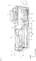
- a vehicle battery pack 10 is housed in a recessed portion 2B formed in a rear floor panel 2A at a rear portion of a vehicle body 2 of a vehicle 1.
- the rear floor panel 2A forms a luggage compartment by a side panel 2C that constitutes a side surface of the vehicle body 2 and a rear panel 2D that constitutes a rear surface of the vehicle body.
- the vehicle battery pack 10 includes a battery case 20 in which battery modules 11 are built.
- the vehicle battery pack 10 includes an inverter 13 serving as a first electrical component that converts electric power from the battery modules 11 (see Fig. 4 ), a switching portion 14 serving as a second electrical component that electrically connects the battery modules 11 to the inverter 13, and a cooling fan 12.
- the vehicle battery pack 10 includes a duct 50 connected to the cooling fan 12.
- the vehicle battery pack 10 includes a housing 30.
- the battery case 20 (see Fig. 4 ), the inverter 13, the switching portion 14, and the duct 50 (see Fig. 6 ) are housed in the housing 30.
- each battery module 11 is formed of an assembled battery in which a plurality of cells are electrically connected.
- the battery case 20 is disposed in a region on a right side from a central portion of the housing 30 in a vehicle width direction. Therefore, a space in which the inverter 13 and the switching portion 14 are arranged is formed in a region on a left side of the battery case 20 in the housing 30, that is, a region on a lateral side of the battery case 20 in the vehicle width direction.
- the cooling fan 12 is disposed on an upper surface of a left rear end portion of the housing 30, and supplies air taken in from outside of the housing 30 to the duct 50.
- the duct 50 includes an upstream duct 51 connected to the cooling fan 12, a branch duct 53 (see Fig. 8 ) connected to a lower portion of the upstream duct 51, an electrical component cooling duct 60 that branches from the branch duct 53 and extends forward to the inverter 13, and a battery cooling duct 70 that branches from the branch duct 53 and extends rightward along a rear surface of the battery case 20.
- a portion where the electrical component cooling duct 60 and the battery cooling duct 70 intersect is the branch duct 53, and a boundary of the branch duct 53 is indicated by a broken line.
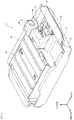
- the inverter 13 and the switching portion 14 are arranged side by side on a vehicle front side and a vehicle rear side in the space formed on the lateral side of the battery case 20 of the housing 30 in the vehicle width direction.
- the inverter 13 is disposed in front of the switching portion 14. Further, the inverter 13 and the switching portion 14 are electrically connected to each other via a bus bar 15.
- the bus bar 15 is formed by forming a conductive flat plate formed of copper or the like in a shape that extends in the vehicle front-rear direction.
- the bus bar 15 constitutes a conductive member in the present invention.
- the inverter 13 includes a first connection portion 13A to which one end portion of the bus bar 15 is connected.
- the switching portion 14 includes a second connection portion 14A to which the other end portion of the bus bar 15 is connected.
- the first connection portion 13A and the second connection portion 14A are arranged such that height positions of the first connection portion 13A and the second connection portion 14A are different.
- the bus bar 15 includes an inclined portion 15A inclined to be higher from the second connection portion 14A toward the first connection portion 13A.
- the first connection portion 13A is disposed on a side opposite to the battery case 20 in the vehicle width direction with respect to the second connection portion 14A.
- the first connection portion 13A is disposed away from the battery case 20, and the second connection portion 14A is disposed close to the battery case 20.
- the bus bar 15 includes curved portions 15B that is curved from the second connection portion 14A to the first connection portion 13A.
- the inverter 13 and the switching portion 14 are arranged at positions lower than an upper surface of the battery case 20.
- the inverter 13 is disposed in front of the switching portion 14, and a rear side bottom surface of the inverter 13 is disposed at a position higher than a front side upper surface of the switching portion 14.
- a bottom surface 30A of the housing 30 includes a first bottom surface portion 30B that is a region that overlaps with the inverter 13 in the upper-lower direction, and a second bottom surface portion 30C that is a region that overlaps with the switching portion 14 in the upper-lower direction.
- the first bottom surface portion 30B includes a bulging portion 30D that bulges upward than the second bottom surface portion 30C to approach an inverter 13 side.
- the inverter 13 is supported on an upper surface of the bulging portion 30D via a bracket 41.
- the cooling fan 12 is provided on a rear end portion of an upper surface of the housing 30.
- the inverter 13 and the cooling fan 12 are arranged at different positions in the height direction. In other words, the inverter 13 is disposed at a position lower than the cooling fan 12.
- the vehicle battery pack 10 includes the duct 50 connected to the cooling fan 12.
- the electrical component cooling duct 60 of the duct 50 includes a vehicle width direction extending portion 62 that extends in the vehicle width direction between the inverter 13 and the switching portion 14.
- the duct 50 includes a front-rear direction extending portion 61 that extends in the vehicle front-rear direction.
- the front-rear direction extending portion 61 includes a facing portion 61A that faces the inverter 13 in the vehicle front-rear direction, and an outer side portion 61B disposed outward than a side end of the inverter 13 in the vehicle width direction.
- a rear end portion of the front-rear direction extending portion 61 is continuous with the branch duct 53 (see Fig. 8 ), and a front end portion of the front-rear direction extending portion 61 is continuous with the vehicle width direction extending portion 62. Accordingly, air that flows from the branch duct 53 into the front-rear direction extending portion 61 changes a direction to a left side at the front end portion of the front-rear direction extending portion 61, flows into the vehicle width direction extending portion 62, and is supplied to the inverter 13.
- the bracket 41 is disposed below the inverter 13.
- a heat dissipation member 13B is provided on a lower surface of the inverter 13 while having a gap with respect to the bracket 41.
- the bracket 41 faces the switching portion 14 in the vehicle front-rear direction.
- An interval between the bracket 41 and the switching portion 14 is set to be smaller than an interval between the inverter 13 and the switching portion 14.
- a right end portion of the inverter 13 is provided with the bracket 40 that supports the right end portion of the inverter 13.
- the inverter 13 and the switching portion 14 are arranged side by side on the vehicle front side and the vehicle rear side in the space formed on the lateral side of the battery case 20 of the housing 30 in the vehicle width direction, and are electrically connected to each other via the bus bar 15.
- the inverter 13 includes the first connection portion 13A to which one end portion of the bus bar 15 is connected.
- the switching portion 14 includes the second connection portion 14A to which the other end portion of the bus bar 15 is connected.
- the first connection portion 13A and the second connection portion 14A are arranged such that the height positions of the first connection portion 13A and the second connection portion 14A are different.
- the bus bar 15 includes the inclined portion 15A inclined to be higher from the second connection portion 14A toward the first connection portion 13A.
- the inverter 13 and the switching portion 14 can be prevented from excessively interfering with the battery case 20, and the inverter 13 and the switching portion 14 can be protected.
- the first bending moment is applied to the bus bar 15, so that the load can be absorbed by the bus bar 15. Therefore, a load applied to the switching portion 14 and a load applied to the inverter 13 from the switching portion 14 can be reduced. As a result, the switching portion 14 and the inverter 13, which are the electrical components, can be protected from an impact.
- the first connection portion 13A is disposed on the side opposite to the battery case 20 in the vehicle width direction with respect to the second connection portion 14A.
- the bus bar 15 includes the curved portions 15B that is curved from the second connection portion 14A to the first connection portion 13A.
- a bending moment generated in the bus bar 15 in the plan view of the vehicle battery pack 10 (second bending moment) can be applied.
- the bus bar 15 can be plastically deformed in a direction in which a first connection portion 13A side is away from the battery case 20, and an impact can be absorbed by the plastic deformation. Therefore, the loads applied to the switching portion 14 and the inverter 13 can be reduced, and the inverter 13 and the switching portion 14 can be protected.
- the first connection portion 13A is disposed on the side opposite to the battery case 20 (outer side of the battery pack in the vehicle width direction) with respect to the second connection portion 14A. Therefore, when the switching portion 14 is about to enter the inverter 13 side, the bus bar 15 is plastically deformed in a predetermined mode, so that the inverter 13 can be moved in a direction away from the battery case 20 having high rigidity (leftward), the inverter 13 can be prevented from interfering with the battery case 20, and the inverter 13 can be protected.
- the inverter 13 and the switching portion 14 are arranged at the positions lower than the upper surface of the battery case 20.
- the inverter 13 is disposed in front of the switching portion 14, and the rear side bottom surface of the inverter 13 is disposed at the position higher than the front side upper surface of the switching portion 14.
- the switching portion 14 and the inverter 13 can be prevented from strongly interfering with each other on side surfaces.
- the inverter 13 and the switching portion 14 are arranged at the positions lower than the upper surface of the battery case 20. Therefore, even when heat generated in the battery case 20 stays in an upper portion in the housing 30, the inverter 13 and the switching portion 14 can be kept away from the heat generated from the battery case 20, and the inverter 13 and the switching portion 14 can be protected from the heat.
- the bottom surface of the housing 30 includes the first bottom surface portion 30B that is the region that overlaps with the inverter 13 in the upper-lower direction, and the second bottom surface portion 30C that is the region that overlaps with the switching portion 14 in the upper-lower direction.
- the first bottom surface portion 30B includes the bulging portion 30D that bulges upward than the second bottom surface portion 30C to approach the inverter 13 side.
- the inverter 13 is supported on the upper surface of the bulging portion 30D via the bracket 41.
- the inverter 13 can be reliably disposed at a position higher than the switching portion 14 without increasing a length dimension of the bracket 41 in the upper-lower direction.
- the inverter 13 can be stably held by the bulging portion 30D and the bracket 41, the bus bar 15 can be easily plastically deformed, and the switching portion 14 can be prevented from entering the inverter 13 side.
- the cooling fan 12 is provided on the rear end portion of the upper surface of the housing 30.
- the inverter 13 and the cooling fan 12 are arranged at different positions in the height direction.
- the inverter 13 and the cooling fan 12 are arranged at different positions in the height direction, even when the cooling fan 12 is moved toward the front side of the vehicle during a rear collision of the vehicle, the cooling fan 12 can be prevented from interfering with the inverter 13, and the inverter 13 can be protected.
- the vehicle battery pack 10 includes the duct 50 connected to the cooling fan 12.
- the duct 50 includes the vehicle width direction extending portion 62 that extends in the vehicle width direction between the inverter 13 and the switching portion 14.
- the duct 50 includes the front-rear direction extending portion 61 that extends in the vehicle front-rear direction.
- the front-rear direction extending portion 61 includes the facing portion 61A that faces the inverter 13 in the vehicle front-rear direction, and the outer side portion 61B disposed outward than the side end of the inverter 13 in the vehicle width direction.
- the bracket 41 is disposed below the inverter 13.
- the heat dissipation member 13B is provided on the lower surface of the inverter 13 while having a gap with respect to the bracket 41. Further, the bracket 41 faces the switching portion 14 in the vehicle front-rear direction.
- the interval between the bracket 41 and the switching portion 14 is set to be smaller than the interval between the inverter 13 and the switching portion 14.
Landscapes
- Engineering & Computer Science (AREA)
- Chemical & Material Sciences (AREA)
- Combustion & Propulsion (AREA)
- Transportation (AREA)
- Mechanical Engineering (AREA)
- Arrangement Or Mounting Of Propulsion Units For Vehicles (AREA)
- Cooling Or The Like Of Electrical Apparatus (AREA)
- Secondary Cells (AREA)
- Battery Mounting, Suspending (AREA)
- Electric Propulsion And Braking For Vehicles (AREA)
- Cooling, Air Intake And Gas Exhaust, And Fuel Tank Arrangements In Propulsion Units (AREA)
Applications Claiming Priority (1)
| Application Number | Priority Date | Filing Date | Title |
|---|---|---|---|
| JP2019146737A JP7275979B2 (ja) | 2019-08-08 | 2019-08-08 | 車両用バッテリパック |
Publications (2)
| Publication Number | Publication Date |
|---|---|
| EP3772425A1 true EP3772425A1 (fr) | 2021-02-10 |
| EP3772425B1 EP3772425B1 (fr) | 2022-06-08 |
Family
ID=71948501
Family Applications (1)
| Application Number | Title | Priority Date | Filing Date |
|---|---|---|---|
| EP20189389.8A Active EP3772425B1 (fr) | 2019-08-08 | 2020-08-04 | Bloc-batterie de véhicule |
Country Status (3)
| Country | Link |
|---|---|
| EP (1) | EP3772425B1 (fr) |
| JP (1) | JP7275979B2 (fr) |
| HU (1) | HUE059833T2 (fr) |
Cited By (1)
| Publication number | Priority date | Publication date | Assignee | Title |
|---|---|---|---|---|
| CN115117531A (zh) * | 2021-03-22 | 2022-09-27 | 本田技研工业株式会社 | 车辆用电池组 |
Citations (5)
| Publication number | Priority date | Publication date | Assignee | Title |
|---|---|---|---|---|
| JP2008062780A (ja) | 2006-09-07 | 2008-03-21 | Honda Motor Co Ltd | 車両における電気機器の冷却構造 |
| US20140299393A1 (en) * | 2011-10-28 | 2014-10-09 | Kawasaki Jukogyo Kabushiki Kaisha | Straddle Electric Vehicle |
| DE102016218098A1 (de) * | 2015-09-30 | 2017-03-30 | Fuji Jukogyo K.K. | Bordbatterie für Fahrzeug |
| US20170320383A1 (en) * | 2014-11-07 | 2017-11-09 | Honda Motor Co., Ltd. | Vehicle |
| US20180035573A1 (en) * | 2016-07-26 | 2018-02-01 | Subaru Corporation | Electrical unit |
Family Cites Families (3)
| Publication number | Priority date | Publication date | Assignee | Title |
|---|---|---|---|---|
| JP6365331B2 (ja) | 2015-02-04 | 2018-08-01 | スズキ株式会社 | 電源装置の冷却構造 |
| JP6879815B2 (ja) | 2017-04-28 | 2021-06-02 | 株式会社Subaru | 車載用バッテリー |
| JP6946718B2 (ja) | 2017-04-28 | 2021-10-06 | トヨタ自動車株式会社 | 車両前部構造 |
-
2019
- 2019-08-08 JP JP2019146737A patent/JP7275979B2/ja active Active
-
2020
- 2020-08-04 EP EP20189389.8A patent/EP3772425B1/fr active Active
- 2020-08-04 HU HUE20189389A patent/HUE059833T2/hu unknown
Patent Citations (5)
| Publication number | Priority date | Publication date | Assignee | Title |
|---|---|---|---|---|
| JP2008062780A (ja) | 2006-09-07 | 2008-03-21 | Honda Motor Co Ltd | 車両における電気機器の冷却構造 |
| US20140299393A1 (en) * | 2011-10-28 | 2014-10-09 | Kawasaki Jukogyo Kabushiki Kaisha | Straddle Electric Vehicle |
| US20170320383A1 (en) * | 2014-11-07 | 2017-11-09 | Honda Motor Co., Ltd. | Vehicle |
| DE102016218098A1 (de) * | 2015-09-30 | 2017-03-30 | Fuji Jukogyo K.K. | Bordbatterie für Fahrzeug |
| US20180035573A1 (en) * | 2016-07-26 | 2018-02-01 | Subaru Corporation | Electrical unit |
Cited By (2)
| Publication number | Priority date | Publication date | Assignee | Title |
|---|---|---|---|---|
| CN115117531A (zh) * | 2021-03-22 | 2022-09-27 | 本田技研工业株式会社 | 车辆用电池组 |
| CN115117531B (zh) * | 2021-03-22 | 2023-10-31 | 本田技研工业株式会社 | 车辆用电池组 |
Also Published As
| Publication number | Publication date |
|---|---|
| HUE059833T2 (hu) | 2023-01-28 |
| JP2021027008A (ja) | 2021-02-22 |
| JP7275979B2 (ja) | 2023-05-18 |
| EP3772425B1 (fr) | 2022-06-08 |
Similar Documents
| Publication | Publication Date | Title |
|---|---|---|
| EP3228527B1 (fr) | Véhicule équipé d'un moteur de déplacement | |
| JP6181723B2 (ja) | 車体構造及び車載用バッテリー | |
| US10358048B2 (en) | Onboard battery for vehicle | |
| US9034502B2 (en) | Battery installation structure for electric vehicles | |
| US9561762B2 (en) | Electric unit | |
| US10093249B2 (en) | Electric device mounting structure | |
| US20210221239A1 (en) | Electric vehicle structure | |
| EP3772425A1 (fr) | Bloc-batterie de véhicule | |
| JP2019166918A (ja) | 電動車両の前部ユニット搭載構造 | |
| JP2019166915A (ja) | 電動車両の前部ユニット搭載構造 | |
| US20140238765A1 (en) | Electric car | |
| JP7155561B2 (ja) | 電動車両の前部ユニット搭載構造 | |
| JP2017077786A (ja) | 車両 | |
| EP3782835B1 (fr) | Bloc-batterie de véhicule | |
| JP7151113B2 (ja) | 電動車両の前部ユニット搭載構造 | |
| JP5292524B1 (ja) | 電気自動車のパワーコントロールユニット | |
| JP2015205595A (ja) | 車載機器の固定構造 | |
| JP7272166B2 (ja) | 車両用バッテリパック | |
| EP4049872B1 (fr) | Vehicule avec structure de protection pour composant électrique | |
| JP2014094653A (ja) | 電動車両 | |
| JP7327170B2 (ja) | 車両用の駆動ユニット | |
| JP2020079034A (ja) | 電気機器の搭載構造 | |
| EP4108491A1 (fr) | Structure de partie avant de véhicule | |
| US20230406083A1 (en) | High voltage device mounting structure of vehicle | |
| JP6873572B2 (ja) | 配線部品の保護構造 |
Legal Events
| Date | Code | Title | Description |
|---|---|---|---|
| PUAI | Public reference made under article 153(3) epc to a published international application that has entered the european phase |
Free format text: ORIGINAL CODE: 0009012 |
|
| STAA | Information on the status of an ep patent application or granted ep patent |
Free format text: STATUS: REQUEST FOR EXAMINATION WAS MADE |
|
| 17P | Request for examination filed |
Effective date: 20200903 |
|
| AK | Designated contracting states |
Kind code of ref document: A1 Designated state(s): AL AT BE BG CH CY CZ DE DK EE ES FI FR GB GR HR HU IE IS IT LI LT LU LV MC MK MT NL NO PL PT RO RS SE SI SK SM TR |
|
| AX | Request for extension of the european patent |
Extension state: BA ME |
|
| GRAP | Despatch of communication of intention to grant a patent |
Free format text: ORIGINAL CODE: EPIDOSNIGR1 |
|
| STAA | Information on the status of an ep patent application or granted ep patent |
Free format text: STATUS: GRANT OF PATENT IS INTENDED |
|
| RIC1 | Information provided on ipc code assigned before grant |
Ipc: B60K 11/06 20060101ALN20220207BHEP Ipc: B60K 1/00 20060101ALN20220207BHEP Ipc: B60K 1/04 20190101AFI20220207BHEP |
|
| INTG | Intention to grant announced |
Effective date: 20220310 |
|
| GRAS | Grant fee paid |
Free format text: ORIGINAL CODE: EPIDOSNIGR3 |
|
| GRAA | (expected) grant |
Free format text: ORIGINAL CODE: 0009210 |
|
| STAA | Information on the status of an ep patent application or granted ep patent |
Free format text: STATUS: THE PATENT HAS BEEN GRANTED |
|
| AK | Designated contracting states |
Kind code of ref document: B1 Designated state(s): AL AT BE BG CH CY CZ DE DK EE ES FI FR GB GR HR HU IE IS IT LI LT LU LV MC MK MT NL NO PL PT RO RS SE SI SK SM TR |
|
| REG | Reference to a national code |
Ref country code: AT Ref legal event code: REF Ref document number: 1496692 Country of ref document: AT Kind code of ref document: T Effective date: 20220615 Ref country code: CH Ref legal event code: EP |
|
| REG | Reference to a national code |
Ref country code: DE Ref legal event code: R096 Ref document number: 602020003449 Country of ref document: DE |
|
| REG | Reference to a national code |
Ref country code: IE Ref legal event code: FG4D |
|
| REG | Reference to a national code |
Ref country code: LT Ref legal event code: MG9D |
|
| REG | Reference to a national code |
Ref country code: NL Ref legal event code: MP Effective date: 20220608 |
|
| PG25 | Lapsed in a contracting state [announced via postgrant information from national office to epo] |
Ref country code: SE Free format text: LAPSE BECAUSE OF FAILURE TO SUBMIT A TRANSLATION OF THE DESCRIPTION OR TO PAY THE FEE WITHIN THE PRESCRIBED TIME-LIMIT Effective date: 20220608 Ref country code: NO Free format text: LAPSE BECAUSE OF FAILURE TO SUBMIT A TRANSLATION OF THE DESCRIPTION OR TO PAY THE FEE WITHIN THE PRESCRIBED TIME-LIMIT Effective date: 20220908 Ref country code: LT Free format text: LAPSE BECAUSE OF FAILURE TO SUBMIT A TRANSLATION OF THE DESCRIPTION OR TO PAY THE FEE WITHIN THE PRESCRIBED TIME-LIMIT Effective date: 20220608 Ref country code: HR Free format text: LAPSE BECAUSE OF FAILURE TO SUBMIT A TRANSLATION OF THE DESCRIPTION OR TO PAY THE FEE WITHIN THE PRESCRIBED TIME-LIMIT Effective date: 20220608 Ref country code: GR Free format text: LAPSE BECAUSE OF FAILURE TO SUBMIT A TRANSLATION OF THE DESCRIPTION OR TO PAY THE FEE WITHIN THE PRESCRIBED TIME-LIMIT Effective date: 20220909 Ref country code: FI Free format text: LAPSE BECAUSE OF FAILURE TO SUBMIT A TRANSLATION OF THE DESCRIPTION OR TO PAY THE FEE WITHIN THE PRESCRIBED TIME-LIMIT Effective date: 20220608 Ref country code: BG Free format text: LAPSE BECAUSE OF FAILURE TO SUBMIT A TRANSLATION OF THE DESCRIPTION OR TO PAY THE FEE WITHIN THE PRESCRIBED TIME-LIMIT Effective date: 20220908 |
|
| REG | Reference to a national code |
Ref country code: AT Ref legal event code: MK05 Ref document number: 1496692 Country of ref document: AT Kind code of ref document: T Effective date: 20220608 |
|
| PG25 | Lapsed in a contracting state [announced via postgrant information from national office to epo] |
Ref country code: RS Free format text: LAPSE BECAUSE OF FAILURE TO SUBMIT A TRANSLATION OF THE DESCRIPTION OR TO PAY THE FEE WITHIN THE PRESCRIBED TIME-LIMIT Effective date: 20220608 Ref country code: LV Free format text: LAPSE BECAUSE OF FAILURE TO SUBMIT A TRANSLATION OF THE DESCRIPTION OR TO PAY THE FEE WITHIN THE PRESCRIBED TIME-LIMIT Effective date: 20220608 |
|
| PG25 | Lapsed in a contracting state [announced via postgrant information from national office to epo] |
Ref country code: NL Free format text: LAPSE BECAUSE OF FAILURE TO SUBMIT A TRANSLATION OF THE DESCRIPTION OR TO PAY THE FEE WITHIN THE PRESCRIBED TIME-LIMIT Effective date: 20220608 |
|
| REG | Reference to a national code |
Ref country code: HU Ref legal event code: AG4A Ref document number: E059833 Country of ref document: HU |
|
| PG25 | Lapsed in a contracting state [announced via postgrant information from national office to epo] |
Ref country code: SM Free format text: LAPSE BECAUSE OF FAILURE TO SUBMIT A TRANSLATION OF THE DESCRIPTION OR TO PAY THE FEE WITHIN THE PRESCRIBED TIME-LIMIT Effective date: 20220608 Ref country code: SK Free format text: LAPSE BECAUSE OF FAILURE TO SUBMIT A TRANSLATION OF THE DESCRIPTION OR TO PAY THE FEE WITHIN THE PRESCRIBED TIME-LIMIT Effective date: 20220608 Ref country code: RO Free format text: LAPSE BECAUSE OF FAILURE TO SUBMIT A TRANSLATION OF THE DESCRIPTION OR TO PAY THE FEE WITHIN THE PRESCRIBED TIME-LIMIT Effective date: 20220608 Ref country code: PT Free format text: LAPSE BECAUSE OF FAILURE TO SUBMIT A TRANSLATION OF THE DESCRIPTION OR TO PAY THE FEE WITHIN THE PRESCRIBED TIME-LIMIT Effective date: 20221010 Ref country code: ES Free format text: LAPSE BECAUSE OF FAILURE TO SUBMIT A TRANSLATION OF THE DESCRIPTION OR TO PAY THE FEE WITHIN THE PRESCRIBED TIME-LIMIT Effective date: 20220608 Ref country code: EE Free format text: LAPSE BECAUSE OF FAILURE TO SUBMIT A TRANSLATION OF THE DESCRIPTION OR TO PAY THE FEE WITHIN THE PRESCRIBED TIME-LIMIT Effective date: 20220608 Ref country code: CZ Free format text: LAPSE BECAUSE OF FAILURE TO SUBMIT A TRANSLATION OF THE DESCRIPTION OR TO PAY THE FEE WITHIN THE PRESCRIBED TIME-LIMIT Effective date: 20220608 Ref country code: AT Free format text: LAPSE BECAUSE OF FAILURE TO SUBMIT A TRANSLATION OF THE DESCRIPTION OR TO PAY THE FEE WITHIN THE PRESCRIBED TIME-LIMIT Effective date: 20220608 |
|
| PG25 | Lapsed in a contracting state [announced via postgrant information from national office to epo] |
Ref country code: PL Free format text: LAPSE BECAUSE OF FAILURE TO SUBMIT A TRANSLATION OF THE DESCRIPTION OR TO PAY THE FEE WITHIN THE PRESCRIBED TIME-LIMIT Effective date: 20220608 Ref country code: IS Free format text: LAPSE BECAUSE OF FAILURE TO SUBMIT A TRANSLATION OF THE DESCRIPTION OR TO PAY THE FEE WITHIN THE PRESCRIBED TIME-LIMIT Effective date: 20221008 |
|
| REG | Reference to a national code |
Ref country code: DE Ref legal event code: R097 Ref document number: 602020003449 Country of ref document: DE |
|
| PG25 | Lapsed in a contracting state [announced via postgrant information from national office to epo] |
Ref country code: MC Free format text: LAPSE BECAUSE OF FAILURE TO SUBMIT A TRANSLATION OF THE DESCRIPTION OR TO PAY THE FEE WITHIN THE PRESCRIBED TIME-LIMIT Effective date: 20220608 Ref country code: AL Free format text: LAPSE BECAUSE OF FAILURE TO SUBMIT A TRANSLATION OF THE DESCRIPTION OR TO PAY THE FEE WITHIN THE PRESCRIBED TIME-LIMIT Effective date: 20220608 |
|
| PLBE | No opposition filed within time limit |
Free format text: ORIGINAL CODE: 0009261 |
|
| STAA | Information on the status of an ep patent application or granted ep patent |
Free format text: STATUS: NO OPPOSITION FILED WITHIN TIME LIMIT |
|
| PG25 | Lapsed in a contracting state [announced via postgrant information from national office to epo] |
Ref country code: LU Free format text: LAPSE BECAUSE OF NON-PAYMENT OF DUE FEES Effective date: 20220804 Ref country code: DK Free format text: LAPSE BECAUSE OF FAILURE TO SUBMIT A TRANSLATION OF THE DESCRIPTION OR TO PAY THE FEE WITHIN THE PRESCRIBED TIME-LIMIT Effective date: 20220608 |
|
| REG | Reference to a national code |
Ref country code: BE Ref legal event code: MM Effective date: 20220831 |
|
| 26N | No opposition filed |
Effective date: 20230310 |
|
| PG25 | Lapsed in a contracting state [announced via postgrant information from national office to epo] |
Ref country code: SI Free format text: LAPSE BECAUSE OF FAILURE TO SUBMIT A TRANSLATION OF THE DESCRIPTION OR TO PAY THE FEE WITHIN THE PRESCRIBED TIME-LIMIT Effective date: 20220608 |
|
| PG25 | Lapsed in a contracting state [announced via postgrant information from national office to epo] |
Ref country code: IE Free format text: LAPSE BECAUSE OF NON-PAYMENT OF DUE FEES Effective date: 20220804 Ref country code: FR Free format text: LAPSE BECAUSE OF NON-PAYMENT OF DUE FEES Effective date: 20220808 |
|
| PG25 | Lapsed in a contracting state [announced via postgrant information from national office to epo] |
Ref country code: BE Free format text: LAPSE BECAUSE OF NON-PAYMENT OF DUE FEES Effective date: 20220831 |
|
| PGFP | Annual fee paid to national office [announced via postgrant information from national office to epo] |
Ref country code: HU Payment date: 20230720 Year of fee payment: 4 Ref country code: DE Payment date: 20230627 Year of fee payment: 4 |
|
| PG25 | Lapsed in a contracting state [announced via postgrant information from national office to epo] |
Ref country code: IT Free format text: LAPSE BECAUSE OF FAILURE TO SUBMIT A TRANSLATION OF THE DESCRIPTION OR TO PAY THE FEE WITHIN THE PRESCRIBED TIME-LIMIT Effective date: 20220608 |
|
| REG | Reference to a national code |
Ref country code: CH Ref legal event code: PL |
|
| PG25 | Lapsed in a contracting state [announced via postgrant information from national office to epo] |
Ref country code: MK Free format text: LAPSE BECAUSE OF FAILURE TO SUBMIT A TRANSLATION OF THE DESCRIPTION OR TO PAY THE FEE WITHIN THE PRESCRIBED TIME-LIMIT Effective date: 20220608 Ref country code: CY Free format text: LAPSE BECAUSE OF FAILURE TO SUBMIT A TRANSLATION OF THE DESCRIPTION OR TO PAY THE FEE WITHIN THE PRESCRIBED TIME-LIMIT Effective date: 20220608 Ref country code: CH Free format text: LAPSE BECAUSE OF NON-PAYMENT OF DUE FEES Effective date: 20230831 |