EP3771684B1 - Industrial truck with a lifting device - Google Patents
Industrial truck with a lifting device Download PDFInfo
- Publication number
- EP3771684B1 EP3771684B1 EP20184405.7A EP20184405A EP3771684B1 EP 3771684 B1 EP3771684 B1 EP 3771684B1 EP 20184405 A EP20184405 A EP 20184405A EP 3771684 B1 EP3771684 B1 EP 3771684B1
- Authority
- EP
- European Patent Office
- Prior art keywords
- lifting
- load
- mast
- control valve
- pressure accumulator
- Prior art date
- Legal status (The legal status is an assumption and is not a legal conclusion. Google has not performed a legal analysis and makes no representation as to the accuracy of the status listed.)
- Active
Links
- 230000000903 blocking effect Effects 0.000 claims description 3
- 239000000725 suspension Substances 0.000 description 14
- 230000004913 activation Effects 0.000 description 10
- 238000013016 damping Methods 0.000 description 9
- 230000007704 transition Effects 0.000 description 7
- 230000004044 response Effects 0.000 description 4
- 238000010586 diagram Methods 0.000 description 2
- 230000010355 oscillation Effects 0.000 description 2
- 230000036316 preload Effects 0.000 description 2
- 230000009172 bursting Effects 0.000 description 1
- 238000010276 construction Methods 0.000 description 1
- 230000008878 coupling Effects 0.000 description 1
- 238000010168 coupling process Methods 0.000 description 1
- 238000005859 coupling reaction Methods 0.000 description 1
- 230000009849 deactivation Effects 0.000 description 1
- 238000006073 displacement reaction Methods 0.000 description 1
- 230000002349 favourable effect Effects 0.000 description 1
- 239000012530 fluid Substances 0.000 description 1
- 239000010720 hydraulic oil Substances 0.000 description 1
- 238000009434 installation Methods 0.000 description 1
- 230000007935 neutral effect Effects 0.000 description 1
- 238000005457 optimization Methods 0.000 description 1
- 230000035939 shock Effects 0.000 description 1
Images

Classifications
-
- B—PERFORMING OPERATIONS; TRANSPORTING
- B66—HOISTING; LIFTING; HAULING
- B66F—HOISTING, LIFTING, HAULING OR PUSHING, NOT OTHERWISE PROVIDED FOR, e.g. DEVICES WHICH APPLY A LIFTING OR PUSHING FORCE DIRECTLY TO THE SURFACE OF A LOAD
- B66F9/00—Devices for lifting or lowering bulky or heavy goods for loading or unloading purposes
- B66F9/06—Devices for lifting or lowering bulky or heavy goods for loading or unloading purposes movable, with their loads, on wheels or the like, e.g. fork-lift trucks
- B66F9/075—Constructional features or details
- B66F9/20—Means for actuating or controlling masts, platforms, or forks
- B66F9/22—Hydraulic devices or systems
-
- B—PERFORMING OPERATIONS; TRANSPORTING
- B66—HOISTING; LIFTING; HAULING
- B66F—HOISTING, LIFTING, HAULING OR PUSHING, NOT OTHERWISE PROVIDED FOR, e.g. DEVICES WHICH APPLY A LIFTING OR PUSHING FORCE DIRECTLY TO THE SURFACE OF A LOAD
- B66F9/00—Devices for lifting or lowering bulky or heavy goods for loading or unloading purposes
- B66F9/06—Devices for lifting or lowering bulky or heavy goods for loading or unloading purposes movable, with their loads, on wheels or the like, e.g. fork-lift trucks
- B66F9/075—Constructional features or details
- B66F9/08—Masts; Guides; Chains
Definitions
- the invention relates to an industrial truck with a lifting device and with a hydraulic pressure accumulator device, the lifting device being provided for raising and lowering a load handling attachment, the lifting device having a hydraulic lifting cylinder device which has a pressure chamber which can be connected to the hydraulic pressure accumulator device, the lifting device is designed as a mast, which is designed as a multiple mast with a standing mast and at least one extension mast that can be raised and lowered relative to the standing mast, in which the load handling device can be raised and lowered, the mast having a free lift with a free lift area and a mast lift with a mast lift area, wherein the lifting cylinder device has at least one free lifting cylinder for raising and lowering the load handling device in the extension mast and has at least one lifting cylinder for raising and lowering the at least one extension mast in the fixed mast.
- industrial trucks have a load handling device which is fastened so that it can move in the vertical direction on a lifting device designed as a mast.
- loads for example loads arranged on pallets, can be lifted, transported and stacked with the load handling device, which is often designed as a load fork.
- a hydraulic lifting cylinder device for raising or lowering the load-carrying device, which can consist of one or more lifting cylinders that are connected directly or indirectly to the load-carrying device, often via a lifting chain or a lifting belt.
- the force required to lift the load is generated by the lifting cylinder device, which is connected to a control directional control valve via a hydraulic lifting line.
- This directional control valve usually has three switching positions, with the lifting line being able to be connected either to a hydraulic pump for raising the load-carrying device or to a container for lowering the load-carrying device or to be shut off to hold the load-carrying device. According to the respective switching position of the directional control valve, the load handling attachment is raised, lowered or held in the current position.
- the lifting cylinder device When the control directional valve is in the closed switching position, the lifting cylinder device represents an at least approximately rigid component, as a result of which the load handling device is not movably coupled to the frame of the industrial truck. As a result of this rigid coupling, vibrations and shocks, for example as a result of driving over bumps in the road, are transmitted immediately and directly from the load handling device with a load arranged thereon to the frame of the industrial truck.
- the load damping device essentially consists of a hydraulic pressure accumulator device which is connected to the pressure chamber of the lifting cylinder device.
- the hydraulic pressure accumulator device is connected to a lifting line leading to the lifting cylinder device.
- the hydraulic pressure accumulator device has the function of a spring. Due to the mass inertia of the load picked up, the impacts coming from the industrial truck and resulting from unevenness in the roadway are cushioned with the hydraulic pressure accumulator device and the load vibrates in relation to the industrial truck.
- the aperture assigned to the hydraulic pressure accumulator device also represents a strong damping of the suspension system formed by the hydraulic pressure accumulator device, so that the aperture acts contrary to the actual intended use of the hydraulic pressure accumulator device.
- the diameter of the aperture must therefore be selected depending on the lifting capacity of the industrial truck, the load weight of the load, the temperature of the hydraulic fluid and the size of the hydraulic pressure accumulator device used, and therefore requires many optimization loops and always forms a corresponding one Compromise.
- the DE 10 2014 113 208 A1 discloses an industrial truck with a duplex mast, in which the lifting cylinder device is assigned a pressure accumulator device designed as a gas pressure accumulator, which can be switched on and off by means of a control valve.
- the gas preload of the gas pressure accumulator is adjusted to the current loading condition by means of a gas preload changing device.
- the DE 10 2016 103 256 A1 discloses an industrial truck with a multiple mast.
- a proportional valve device is provided in addition to a control valve device controlling the lifting cylinder influences the flow conditions of the free lift cylinder and mast lift cylinder during the transition between free lift and mast lift.
- the EP 3 153 456 A1 discloses a telescopic handler in which the telescopic arm can be raised and lowered by means of a lifting cylinder and extended and retracted by means of an extension cylinder.
- a pressure accumulator device is assigned to the extension cylinder in order to avoid major damage to the telehandler in the event of a frontal collision, ie the telescopic arm hitting an obstacle.
- a safety device is assigned to the pressure accumulator device, which includes a sensor that detects the extension path of the extension cylinder and a control valve with which the pressure accumulator device can be switched on and off the extension cylinder.
- the safety device with the activation/deactivation of the pressure accumulator device depending on the extension path of the extension cylinder represents a safety function to prevent the pressure accumulator device from bursting when the extension cylinder is extended far enough in the event of a frontal collision due to the large amount of pressure medium flowing into the pressure accumulator device.
- the EP 1 659 087 A2 discloses a suspension system for a boom or a front loader arm of a telehandler, wheel loader or tractor.
- a pressure medium accumulator is connected to the displacement of a hydraulic cylinder and can be switched on and off by means of a valve.
- a sensor is provided on the lifting cylinder, which sensor detects the position of the hydraulic cylinder, for example a predetermined position of the hydraulic cylinder. The sensor activates the suspension function if the sensor detects the lowered position of the hydraulic cylinder. The suspension function itself is then activated with an additional activation switch.
- the WO 2013/155178 A1 discloses a telehandler with hydraulic suspension of the telescopic arm, with a pressure accumulator being able to be switched on and off the lifting cylinder of the telescopic arm by means of a valve. With a position sensor, the position of the telescopic arm is recorded.
- the telescopic arm occurs due to the loading of the pressure accumulator with pressure medium from the pressure chamber of the lifting cylinder, the movement of the telescopic arm is detected with the position sensor and the suspension is deactivated if, after activation of the suspension function, the movement of the telescopic arm exceeds a predetermined limit value.
- the object of the present invention is to provide an improved industrial truck of the type mentioned at the outset.
- a control valve is provided, the pressure accumulator device being able to be switched on and off by means of the control valve depending on the lifting height of the load-carrying means, the pressure accumulator device being switched on below a lifting height limit value of the load-carrying device by corresponding activation of the control valve and above the lifting height limit value of the load-carrying means, the pressure accumulator device is switched off by appropriate activation of the control valve, the lift height limit value being within the free lift range of the free lift.
- the hydraulic pressure accumulator device can be switched on and off in a simple manner with the control valve, so that there is no need for a constantly active orifice plate associated with the hydraulic pressure accumulator device, as is the case in the prior art with the disadvantages and compromises associated with the orifice plate.
- the pressure accumulator device below a lifting height limit value of the load handling device, the pressure accumulator device is activated by appropriate activation of the control valve, and above the lifting height limit value of the load handling device, the pressure accumulator device is deactivated by appropriate activation of the control valve. Since the incorrect response of the line rupture safety valve, particularly at the lift stage transitions takes place, by switching off the hydraulic pressure accumulator device above a specific lifting height limit value, an erroneous response of the line rupture protection valve can be avoided in a simple manner. Since the hydraulic pressure accumulator device is switched on below the lift height limit by means of the control valve, the spring and damping properties of the hydraulic pressure accumulator device can be fully utilized, i.e.
- the lifting device is designed as a lifting frame, which is designed as a multiple lifting frame with a standing mast and at least one extension mast that can be raised and lowered relative to the standing mast, in which the load handling device can be raised and lowered, the lifting frame having a free lift with a free lift area and a mast lift with a mast lifting area, wherein the lifting cylinder device has at least one free lifting cylinder for raising and lowering the load handling device in the extending mast and has at least one lifting cylinder for raising and lowering the at least one extending mast in the standing mast, the lifting height limit value being within the free lifting area of the free lift.
- Such a multiple lifting frame can be designed as a duplex mast or as a triplex mast, which is equipped with a free lift for the load handling device.
- Duplex masts have a stationary mast and an extension mast that can be raised and lowered on the stationary mast, the load handling device being arranged on the extension mast so that it can be raised and lowered.
- the lifting cylinder device has one or more lifting cylinders for raising and lowering the extension mast in the Fixed mast and at least one additional free lift cylinder for raising and lowering the load handling device on the extending mast.
- Triplex masts have a stationary mast, a first extension mast guided on the stationary mast and a second second extension mast guided on the first extension mast, with the load handling device being arranged such that it can be raised and lowered on the second extension mast.
- the lifting cylinder device has one or more lifting cylinders for raising and lowering the two extension masts and at least one additional free lift cylinder for raising and lowering the load handling device on the second extension mast.
- the line rupture safety valve responds incorrectly, particularly at the lift stage transitions between mast lift and free lift, the fact that the lift height limit value is within the free lift range of the free lift and thus the lift height limit value is smaller than the upper end of the free lift range can result in the hydraulic pressure accumulator device being switched off above the lift height limit value an erroneous response of the line rupture protection valve can be avoided in a simple manner. Since the hydraulic pressure accumulator device is switched on by means of the control valve below the lift height limit value, the spring and damping properties of the hydraulic pressure accumulator device can be fully utilized, i.e. without damping, during transport work of the industrial truck, in which the load handling device with a load picked up is lowered below the lift height limit value.
- the hydraulic pressure accumulator device is switched off by means of the control valve above the lifting height limit value. Storing and retrieving a load, in which the load handling attachment is raised above the lifting height limit, can therefore be carried out without disturbing after-oscillation and without the risk of a power failure safety valve responding and the associated risk of the truck tipping over and component failure.
- the control valve can be actuated electrically between a switched-on position and a switched-off position, and the control valve can be actuated with an electronic control device Connection, wherein the electronic control device is connected to a lifting height of the lifting device detecting the lifting height sensor device.
- the control valve can be controlled in a simple manner in such a way that the pressure accumulator device is switched on below the lifting height limit value and switched off above the lifting height limit value.
- the lift height sensor device can continuously detect the lift height of the load handling device.
- the lifting height limit value is then advantageously stored in the electronic control device, so that the control device can use the lifting height measured with the lifting height sensor to determine whether the load handling device is above or below the lifting height limit value.
- the lift height sensor device is designed as a lift height switch with which the lift height limit value can be detected.
- a lifting height switch which is attached to a mast of the industrial truck in such a way that it detects the lifting height limit value of the load handling device, it can be determined with little construction effort whether the load handling device is above or below the lifting height limit value.
- the switch-on position of the control valve is designed as a flow position and the switch-off position of the control valve is designed as a throttle position or blocking position. If the disconnected position is designed as a throttle position, the hydraulic pressure accumulator device is throttled in the disconnected position of the control valve.
- the pressure accumulator device is connected by means of a branch line to the pressure chamber of the lifting cylinder device or to a lifting line leading from a control directional valve controlling the lifting device to the lifting cylinder device.
- the invention enables a number of advantages:
- the fact that the hydraulic pressure accumulator device is switched off above the lifting height limit value means that the load-carrying means can be lifted above the lifting height limit value safely and sensitively to be worked.
- the hydraulic pressure accumulator device is switched on below the lift height limit value, the suspension behavior of the suspension system formed by the hydraulic pressure accumulator device can be fully utilized with the load suspension device lowered below the lift height limit value, since there is no throttled and/or damped behavior.
- service costs can be reduced, which arise due to a line rupture safety valve responding incorrectly.
- the time-consuming orifice adjustment of the orifice assigned to the hydraulic pressure accumulator device is no longer necessary.
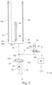
- an industrial truck 1 designed for example as a counterbalanced forklift truck, is shown as an example of an industrial truck.
- the industrial truck 1 is provided in the front area with a lifting device 2 designed as a mast for raising and lowering a load lifting device 3 carrying a load L.
- the industrial truck 1 is provided with a counterweight 4 in the rear area.
- the industrial truck 1 comprises a vehicle body 5 with a frame and a driver's canopy 6 which is arranged on the vehicle body 5 and within which a driver's workplace 7 is located.
- the driver's workplace 7 includes a driver's seat, not shown in detail, a steering device and at least one pedal arranged in a footwell for controlling a drive, not shown in detail.
- the working hydraulics can optionally a Tilting drive 10 of the mast and an additional consumer include, for example, a side shift drive for the load handling device 3.
- the truck 1 is supported by front wheels 11 and one or more rear wheels 12 on a roadway.
- the mast is designed as a multiple mast in the form of a duplex mast.
- the duplex mast comprises a stationary mast 2a, which is formed by two lateral vertical mast profiles arranged spaced apart in the transverse direction of the vehicle.
- the vertical mast 2a can be arranged on the industrial truck 1 so as to be adjustable in inclination by means of the tilting drive 10, which is formed by tilting cylinders.
- an extension mast (not shown in detail) is arranged such that it can be raised and lowered, on which the load handling device 3 is arranged such that it can be raised and lowered.
- the load handling device 3 is formed by a load fork with two forks 3a.
- the forks 3a are arranged on a fork carrier 3b, which is arranged on the extension mast so that it can be adjusted in height.
- the lifting device 2 For raising and lowering the lifting device 3, the lifting device 2 has a hydraulic lifting cylinder device 15 as a lifting drive figure 2 is shown in more detail.
- the industrial truck 1 has an unsprung chassis.
- the front wheels 11 and the rear wheels 12 are arranged without suspension on the vehicle body 5 and the counterweight 4, respectively.
- the lifting device 2 is also attached without suspension to the vehicle body 5 or to a drive axle carrying the front wheels 11 .
- FIG 2 a hydraulic circuit diagram of the lifting drive of the industrial truck 1 according to the invention is shown.
- a hydraulic pump 20 draws in pressure medium, for example hydraulic oil, from a container 21 and is connected via a delivery line 22 to a directional control valve 23, with which the lifting cylinder device 15 and thus the lifting and lowering movement of the load handling device 3 can be controlled.
- a lifting line 25 connects the directional control valve 23 to a pressure chamber 26 of the lifting cylinder device 15.
- the directional control valve 23, which preferably throttles in intermediate positions, has three switching positions. In a neutral position 23a, which the directional control valve 23, for example, as a result of spring force occupies the rest position, the delivery line 22 and the lifting line 25 are closed and the lifting line 25 is blocked.
- the control directional control valve 23 is in this switching position when no signal for raising or lowering the load L is specified by the operator.
- the control directional valve 23 is actuated into a lifting position 23b, in which the pump 20 is connected to the lifting line 25 of the lifting cylinder device 15, as a result of which piston rods of the lifting cylinder device 15 extend upwards as a result of the pressure present in a pressure chamber 26 of the lifting cylinder device 15.
- the control directional valve 23 is actuated into a lowering position 23c, in which the lifting line 25 of the lifting cylinder device 15 is connected to a tank line 27 which is connected to the control directional valve 23 and runs to the container 21, as a result of which the pressure chamber 26 of the lifting cylinder device 15 is connected to the Container 21 is connected and retract the piston rods of the lifting cylinder device 15 down.
- the lifting cylinder device 15 has two lifting cylinders 15a, 15b of a mast lift, which are used to raise and lower the or the extension masts of the multiple lifting frame.
- the lifting cylinder device 15 also has a free lifting cylinder 15c of a free lift, which is used to raise and lower the load handling device 3 on the extension mast.
- the lifting cylinders 15a, 15b, 15c are each designed as single-acting plunger cylinders, each having a piston rod extending in a cylinder housing and forming a corresponding pressure chamber 26 between the cylinder housing and the piston rod.
- the lifting cylinders 15a, 15b are fluidically connected in parallel in the illustrated embodiment.
- the free lift cylinder 15c is fluidically connected in series with the lift cylinder 15a in the exemplary embodiment shown. It goes without saying that, alternatively, the free lift cylinder 15c can be connected fluidically in parallel with the lift cylinders 15a, 15b.
- the free lifting cylinder 15c is connected to the fork carrier 3b via a lifting chain or a lifting belt.
- further lifting chains can be attached to the mast or lifting belts can be provided in order to couple the extension movement of several extension masts.
- a line rupture safety valve 16a, 16b, 16c is arranged at the lower ends of the lifting cylinders 15a, 15b, 15c.
- the pressure chambers 26 of the lifting cylinders 15a, 15b, 15c can be connected to a hydraulic pressure accumulator device 30 to reduce the vibrations and load impacts of the load L acting on the vehicle body 5 when driving over bumps in the roadway.
- the pressure accumulator device 30 is connected by means of a branch line 31 to the lifting line 25 leading from the control directional control valve 23 to the lifting cylinder device 15 .
- the pressure accumulator device 30 can be switched on and off by means of a control valve 35 depending on the lifting height of the load handling device 3 .
- the pressure accumulator device 30 is activated by appropriate activation of the control valve 35 and above the lifting height limit value HG of the load-carrying device 3 the pressure accumulator device 30 is deactivated by appropriate activation of the control valve 35.
- control valve 35 can be actuated electrically between a switch-on position 35a and a switch-off position 35b.
- the control valve 35 is connected to an electronic control device 36 which is connected to a lifting height sensor device 37 which detects the lifting height of the load-carrying means 3 .
- the switch-on position 35a of the control valve 35 is designed as a flow position.
- the switch-off position 35b of the control valve 35 is designed as a throttle position in the exemplary embodiment shown.
- the switched-off position 35b can be designed as a blocked position.
- control valve 35 is actuated by a spring 40 into the switched-on position 35a and can be actuated into the switched-off position 35b by means of an electrical actuating device 41, for example a switching magnet.
- the control valve 35 is thus designed as an electrically operated 2/2-way valve, for example a switching valve.
- the lifting height sensor device 37 is designed as a lifting height switch 38 with which the lifting height limit value HG of the load-receiving means 3 can be detected.
- the lifting height switch 38 is arranged, for example, on the vertical mast 2a of the mast and interacts with a counterpart 39 arranged on the load handling device 3, for example on the fork carriage 3b.
- the fork carriage 3b in the lowered extension mast can be raised to the upper end of the lowered extension mast for the free lift of the load handling device 3.
- the achievable with the free lift cylinder 15c free lift of the load handling device (forks 3a) is in figure 1 illustrated with a free lift area FH.
- the load-carrying means 3 can be raised together with the extension mast by means of the lifting cylinders 15a, 15b.
- the achievable with the lifting cylinders 15a, 15b Masthub is in the figure 1 illustrated with a mast lift range MH.
- the lift height limit HG is within the free lift range FH of the free lift.
- the lifting height switch 38 is arranged on the mast in such a way that it is actuated by the counterpart 39 on the load-carrying means 3 when the load-carrying means 3 is raised before the load-carrying means 3 reaches the upper end of the free lift range FH.
- the lifting height limit value HG is therefore smaller than the upper end of the free lift FH of the load handling device 3.
- the control valve 35 is actuated into the switch-on position 35a and the pressure accumulator device 30 is switched on and is therefore effective. If the load handling attachment 3 is above the lifting height limit value HG, the control valve 35 actuated in the disconnected position 35b and disconnected the pressure accumulator device 30 and thus not effective. Since the lift height limit value HG is less than the upper end of the free lift FH of the load handling attachment 3, the pressure accumulator device 30 is switched off during the transition from the free lift to the mast lift, so that an incorrect response and engagement of the power failure safety valves 16a, 16b, 16c can be effectively avoided.
- the hydraulic pressure accumulator device 30 Since the hydraulic pressure accumulator device 30 is switched on below the lift height limit value HG by means of the control valve 35 actuated in the switched-on position 35a, the spring and damping properties of the hydraulic pressure accumulator device 30 during transport work of the industrial truck 1 in which the load handling device 3 with the load L picked up is below the lift height limit value HG is lowered, can be fully utilized, i.e. without damping. Above the lifting height limit value, the hydraulic pressure accumulator device 30 is switched off by means of the control valve 35 actuated into the switched-off position 35b.
Landscapes
- Engineering & Computer Science (AREA)
- Transportation (AREA)
- Structural Engineering (AREA)
- Civil Engineering (AREA)
- Life Sciences & Earth Sciences (AREA)
- Geology (AREA)
- Mechanical Engineering (AREA)
- Chemical & Material Sciences (AREA)
- Combustion & Propulsion (AREA)
- Forklifts And Lifting Vehicles (AREA)
Description
Die Erfindung betrifft ein Flurförderzeug mit einer Hubvorrichtung und mit einer hydraulischen Druckspeichereinrichtung, wobei die Hubvorrichtung zum Anheben und Absenken eines Lastaufnahmemittels vorgesehen ist, wobei die Hubvorrichtung eine hydraulische Hubzylindereinrichtung aufweist, die einen Druckraum aufweist, der mit der hydraulischen Druckspeichereinrichtung verbindbar ist, wobei die Hubvorrichtung als Hubgerüst ausgebildet ist, das als Mehrfachhubgerüst mit einem Standmast und zumindest einem relativ zu dem Standmast anhebbaren und absenkbaren Ausfahrmast ausgeführt ist, in dem das Lastaufnahmemittel anhebbar und absenkbar ist, wobei das Hubgerüst einen Freihub mit einem Freihubbereich und einen Masthub mit einem Masthubbereich aufweist, wobei die Hubzylindereinrichtung zumindest einen Freihubzylinder zum Anheben und Absenken des Lastaufnahmemittel in dem Ausfahrmast aufweist und zumindest einen Hubzylinder zum Anheben und Absenken des mindestens einen Ausfahrmastes in dem Standmast aufweist.The invention relates to an industrial truck with a lifting device and with a hydraulic pressure accumulator device, the lifting device being provided for raising and lowering a load handling attachment, the lifting device having a hydraulic lifting cylinder device which has a pressure chamber which can be connected to the hydraulic pressure accumulator device, the lifting device is designed as a mast, which is designed as a multiple mast with a standing mast and at least one extension mast that can be raised and lowered relative to the standing mast, in which the load handling device can be raised and lowered, the mast having a free lift with a free lift area and a mast lift with a mast lift area, wherein the lifting cylinder device has at least one free lifting cylinder for raising and lowering the load handling device in the extension mast and has at least one lifting cylinder for raising and lowering the at least one extension mast in the fixed mast.
Flurförderzeuge weisen in der Regel ein Lastaufnahmemittel auf, die an einer als Hubgerüst ausgebildeten Hubvorrichtung in vertikaler Richtung beweglich befestigt ist. Mit dem häufig als Lastgabel ausgeführten Lastaufnahmemittel können verschiedenartige, beispielsweise auf Paletten angeordnete Lasten angehoben, transportiert und gestapelt werden.As a rule, industrial trucks have a load handling device which is fastened so that it can move in the vertical direction on a lifting device designed as a mast. Various types of loads, for example loads arranged on pallets, can be lifted, transported and stacked with the load handling device, which is often designed as a load fork.
Zum Anheben oder Absenken des Lastaufnahmemittels ist eine hydraulische Hubzylindereinrichtung vorgesehen, die aus einem oder mehreren Hubzylindern bestehen kann, die direkt oder indirekt, häufig über eine Hubkette oder einen Hubriemen, mit dem Lastaufnahmemittel verbunden sind. Die zum Anheben der Last erforderliche Kraft wird durch die Hubzylindereinrichtung erzeugt, welcher über eine hydraulische Hubleitung mit einem Steuerwegeventil verbunden ist. Dieses Steuerwegeventil weist in der Regel drei Schaltstellungen auf, wobei die Hubleitung wahlweise zum Anheben des Lastaufnahmemittels mit einer Hydraulikpumpe oder zum Absenken des Lastaufnahmemittels mit einem Behälter verbunden oder zum Halten des Lastaufnahmemittels abgesperrt werden kann. Entsprechend der jeweiligen Schaltstellung des Steuerwegeventils wird das Lastaufnahmemittel angehoben, abgesenkt oder in der momentanen Position gehalten.A hydraulic lifting cylinder device is provided for raising or lowering the load-carrying device, which can consist of one or more lifting cylinders that are connected directly or indirectly to the load-carrying device, often via a lifting chain or a lifting belt. The force required to lift the load is generated by the lifting cylinder device, which is connected to a control directional control valve via a hydraulic lifting line. This directional control valve usually has three switching positions, with the lifting line being able to be connected either to a hydraulic pump for raising the load-carrying device or to a container for lowering the load-carrying device or to be shut off to hold the load-carrying device. According to the respective switching position of the directional control valve, the load handling attachment is raised, lowered or held in the current position.
Bei geschlossener Schaltstellung des Steuerwegeventils stellt die Hubzylindereinrichtung ein zumindest annähernd starres Bauteil dar, wodurch das Lastaufnahmemittel nicht beweglich an den Rahmen des Flurförderzeugs gekoppelt ist. Infolge dieser starren Koppelung werden Schwingungen und Stöße, beispielsweise infolge Fahrens über Fahrbahnunebenheiten, unmittelbar und direkt von dem Lastaufnahmemittel mit einer hierauf angeordneten Last auf den Rahmen des Flurförderzeugs übertragen.When the control directional valve is in the closed switching position, the lifting cylinder device represents an at least approximately rigid component, as a result of which the load handling device is not movably coupled to the frame of the industrial truck. As a result of this rigid coupling, vibrations and shocks, for example as a result of driving over bumps in the road, are transmitted immediately and directly from the load handling device with a load arranged thereon to the frame of the industrial truck.
Um sensible, beispielsweise leicht zerbrechliche, Lasten während des Transports mit dem Flurförderzeug zu schützen, ist es bekannt, Flurförderzeug mit einer Lastdämpfungseinrichtung auszustatten. Die Lastdämpfungseinrichtung besteht im Wesentlichen aus einer hydraulischen Druckspeichereinrichtung, die mit dem Druckraum der Hubzylindereinrichtung verbunden ist. In der Regel ist die hydraulischen Druckspeichereinrichtung an eine zu der Hubzylindereinrichtung geführte Hubleitung angeschlossen. Die hydraulischen Druckspeichereinrichtung weist hierbei die Funktion einer Feder auf. Durch die Massenträgheit der aufgenommen Last werden mit der hydraulischen Druckspeichereinrichtung die aus dem Flurförderzeug kommenden Stöße, die aus Fahbahnunebenheiten resultieren, abgefedert und die Last schwingt in Relation zum Flurförderzeug.In order to protect sensitive, for example easily breakable, loads during transport with the industrial truck, it is known to equip the industrial truck with a load damping device. The load damping device essentially consists of a hydraulic pressure accumulator device which is connected to the pressure chamber of the lifting cylinder device. As a rule, the hydraulic pressure accumulator device is connected to a lifting line leading to the lifting cylinder device. In this case, the hydraulic pressure accumulator device has the function of a spring. Due to the mass inertia of the load picked up, the impacts coming from the industrial truck and resulting from unevenness in the roadway are cushioned with the hydraulic pressure accumulator device and the load vibrates in relation to the industrial truck.
Mit einer derartigen hydraulischen Druckspeichereinrichtung gehen jedoch aus bestimmte Nachteile einher. Beispielsweise bei ruckartigen Senkenbewegungen des Lastaufnahmemittels, insbesondere bei Hubstufenübergängen, beispielsweise zwischen einem Freihub und einem Masthub, und dem an den Hubstufenübergängen einhergehenden Druckanstieg bzw. Druckabfall, kann ein vorhandenes Leitungsbruchsicherungsventil fälschlicherweise ansprechen, was zu einem abrupten Stop der Senkenbewegung des Lastaufnahmemittels führt. Der abrupte Stop der Senkenbewegung bei ansprechendem Leitungsbruchsicherungsventil führt zu einer hohen Belastung der Bauteile und kann zu einem standsicherheitskritschen Fahrverhalten des Flurförderzeugs führen.However, certain disadvantages are associated with such a hydraulic accumulator device. For example, in the case of jerky lowering movements of the load-carrying device, especially in the case of lifting stage transitions, for example between a free lift and a mast lift, and the pressure increase or pressure drop associated with the lifting stage transitions, an existing line break safety valve can respond incorrectly, which leads to an abrupt stop of the lowering movement of the load-carrying device. The abrupt stop of the lowering movement when the line rupture safety valve responds places a high load on the components and can lead to a driving behavior of the truck that is critical to the stability.
Um ein fälschlicherweise stattfindendes Ansprechen und Einfallen des Leitungsbruchsicherungsventils zu vermeiden, ist es bekannt, der hydraulischen Druckspeichereinrichtung in Abhängigkeit von der Tragfähigkeit des Flurförderzeugs und des Typs der Hubgerüstes eine unterschiedlich große Blende zuzuordnen, die ständig aktiv ist und das Ansprechen und somit das Einfallen des Leitungsbruchsicherungsventils verhindern soll.In order to prevent the line rupture safety valve from responding and dropping in by mistake, it is known to assign the hydraulic pressure accumulator device an orifice of different sizes, depending on the load capacity of the industrial truck and the type of mast, which is constantly active and prevents the line rupture safety valve from responding and thus dropping in should prevent.
Die der hydraulischen Druckspeichereinrichtung zugeordnete Blende stellt jedoch auch eine starke Dämpfung des von der hydraulischen Druckspeichereinrichtung gebildeten Federungssystems dar, so dass die Blende gegenläufig zu dem eigentlichen Verwendungszweck der hydraulischen Druckspeichereinrichtung agiert.However, the aperture assigned to the hydraulic pressure accumulator device also represents a strong damping of the suspension system formed by the hydraulic pressure accumulator device, so that the aperture acts contrary to the actual intended use of the hydraulic pressure accumulator device.
Die Wahl des Durchmessers der Blende muss bei bekannten Flurförderzeugen des Standes der Technik deshalb in Abhängigkeit von der Tragfähigkeit des Flurförderzeugs, des Lastgewichts der Last, der Temperatur der Hydraulikflüssigkeit und der verwendeten Größe der hydraulischen Druckspeichereinrichtung erfolgen und erfordert daher vieler Optimierungsschleifen und bildet immer einen entsprechenden Kompromiss.In known industrial trucks of the prior art, the diameter of the aperture must therefore be selected depending on the lifting capacity of the industrial truck, the load weight of the load, the temperature of the hydraulic fluid and the size of the hydraulic pressure accumulator device used, and therefore requires many optimization loops and always forms a corresponding one Compromise.
Aus der
Die
Die
Die
Die
Die
Der vorliegenden Erfindung liegt die Aufgabe zugrunde, ein Flurförderzeug der eingangs genannten Gattung zur Verfügung zu stellen, das verbessert ist.The object of the present invention is to provide an improved industrial truck of the type mentioned at the outset.
Diese Aufgabe wird erfindungsgemäß dadurch gelöst, dass ein Steuerventil vorgesehen ist, wobei die Druckspeichereinrichtung mittels des Steuerventils in Abhängigkeit von der Hubhöhe des Lastaufnahmemittels zuschaltbar und wegschaltbar ist, wobei unterhalb eines Hubhöhengrenzwertes des Lastaufnahmemittels die Druckspeichereinrichtung durch entsprechende Ansteuerung des Steuerventils zugeschaltet ist und oberhalb des Hubhöhengrenzwertes des Lastaufnahmemittels die Druckspeichereinrichtung durch entsprechende Ansteuerung des Steuerventils weggeschaltet ist, wobei der Hubhöhengrenzwert innerhalb des Freihubbereichs des Freihubs ist.This object is achieved according to the invention in that a control valve is provided, the pressure accumulator device being able to be switched on and off by means of the control valve depending on the lifting height of the load-carrying means, the pressure accumulator device being switched on below a lifting height limit value of the load-carrying device by corresponding activation of the control valve and above the lifting height limit value of the load-carrying means, the pressure accumulator device is switched off by appropriate activation of the control valve, the lift height limit value being within the free lift range of the free lift.
Mit dem Steuerventil kann auf einfache Weise die hydraulische Druckspeichereinrichtung zugeschaltet und weggeschaltet werden, so dass keine der hydraulischen Druckspeichereinrichtung zugeordnete und ständig aktive Blende wie im Stand der Technik mit den mit der Blende einhergehenden Nachteilen und Kompromissen erforderlich ist.The hydraulic pressure accumulator device can be switched on and off in a simple manner with the control valve, so that there is no need for a constantly active orifice plate associated with the hydraulic pressure accumulator device, as is the case in the prior art with the disadvantages and compromises associated with the orifice plate.
Gemäß der Erfindung ist unterhalb eines Hubhöhengrenzwertes des Lastaufnahmemittels die Druckspeichereinrichtung durch entsprechende Ansteuerung des Steuerventils zugeschaltet und ist oberhalb des Hubhöhengrenzwertes des Lastaufnahmemittels die Druckspeichereinrichtung durch entsprechende Ansteuerung des Steuerventils weggeschaltet. Da das fälschlicherweise stattfindende Ansprechen des Leitungsbruchsicherungsventils insbesondere an den Hubstufenübergängen erfolgt, kann durch das Wegschalten der hydraulischen Druckspeichereinrichtung oberhalb eines bestimmten Hubhöhengrenzwertes auf einfache Weise ein fälschlicherweise stattfindendes Ansprechen des Leitungsbruchsicherungsventils vermieden werden. Da die hydraulische Druckspeichereinrichtung unterhalb des Hubhöhengrenzwertes mittels des Steuerventils zugeschaltet ist, können die Feder- und Dämpfungseigenschaften der hydraulischen Druckspeichereinrichtung bei Transportarbeiten des Flurförderzeugs, in denen das Lastaufnahmemittel mit einer aufgenommenen Last unter den Hubhöhengrenzwert abgesenkt ist, voll, d.h. ohne Dämpfung, ausgenutzt werden. Oberhalb des Hubhöhengrenzwertes ist die hydraulische Druckspeichereinrichtung mittels des Steuerventils abgeschaltet. Ein- und Auslagerungsarbeiten einer Last, in denen das Lastaufnahmemittel über den Hubhöhengrenzwert angehoben ist, sind somit ohne störendes Nachschwingen sowie ohne Gefahr eines ansprechenden Leistungsbruchsicherungsventils möglich und der damit einhergehenden Gefahr bezüglich Kippstabilität des Flurförderzeugs und Bauteilversagen.According to the invention, below a lifting height limit value of the load handling device, the pressure accumulator device is activated by appropriate activation of the control valve, and above the lifting height limit value of the load handling device, the pressure accumulator device is deactivated by appropriate activation of the control valve. Since the incorrect response of the line rupture safety valve, particularly at the lift stage transitions takes place, by switching off the hydraulic pressure accumulator device above a specific lifting height limit value, an erroneous response of the line rupture protection valve can be avoided in a simple manner. Since the hydraulic pressure accumulator device is switched on below the lift height limit by means of the control valve, the spring and damping properties of the hydraulic pressure accumulator device can be fully utilized, i.e. without damping, during transport work of the industrial truck, in which the load handling device with a load picked up is lowered below the lift height limit. The hydraulic pressure accumulator device is switched off by means of the control valve above the lifting height limit value. Storing and retrieving a load, in which the load handling attachment is raised above the lifting height limit, is therefore possible without disturbing oscillations and without the risk of a power failure safety valve responding and the associated risk of the truck tipping stability and component failure.
Die Hubvorrichtung ist erfindungsgemäß als Hubgerüst ausgebildet, das als Mehrfachhubgerüst mit einem Standmast und zumindest einem relativ zu dem Standmast anhebbaren und absenkbaren Ausfahrmast ausgeführt ist, in dem das Lastaufnahmemittel anhebbar und absenkbar ist, wobei das Hubgerüst einen Freihub mit einem Freihubbereich und einen Masthub mit einem Masthubbereich aufweist, wobei die Hubzylindereinrichtung zumindest einen Freihubzylinder zum Anheben und Absenken des Lastaufnahmemittel in dem Ausfahrmast aufweist und zumindest einen Hubzylinder zum Anheben und Absenken des mindestens einen Ausfahrmastes in dem Standmast aufweist, wobei der Hubhöhengrenzwert innerhalb des Freihubbereichs des Freihubs ist.According to the invention, the lifting device is designed as a lifting frame, which is designed as a multiple lifting frame with a standing mast and at least one extension mast that can be raised and lowered relative to the standing mast, in which the load handling device can be raised and lowered, the lifting frame having a free lift with a free lift area and a mast lift with a mast lifting area, wherein the lifting cylinder device has at least one free lifting cylinder for raising and lowering the load handling device in the extending mast and has at least one lifting cylinder for raising and lowering the at least one extending mast in the standing mast, the lifting height limit value being within the free lifting area of the free lift.
Ein derartiges Mehrfachhubgerüst kann als Duplexmast oder als Triplexmast ausgeführt sein, das mit einem Freihub für das Lastaufnahmemittel ausgerüstet ist.Such a multiple lifting frame can be designed as a duplex mast or as a triplex mast, which is equipped with a free lift for the load handling device.
Duplex-Hubgerüste weisen einen Standmast und einen an dem Standmast anhebbaren und absenkbaren Ausfahrmast auf, wobei an dem Ausfahrmast das Lastaufnahmemittel anhebbar und absenkbar angeordnet ist. Bei Duplex-Hubgerüsten mit Freihub für das Lastaufnahmemittel weist die Hubzylindereinrichtung einen oder mehrere Hubzylinder zum Anheben und Absenken des Ausfahrmastes in dem Standmast und zumindest einen zusätzlichen Freihubzylinder zum Anheben und Absenken des Lastaufnahmemittels an dem Ausfahrmast auf.Duplex masts have a stationary mast and an extension mast that can be raised and lowered on the stationary mast, the load handling device being arranged on the extension mast so that it can be raised and lowered. In duplex masts with free lift for the load handling device, the lifting cylinder device has one or more lifting cylinders for raising and lowering the extension mast in the Fixed mast and at least one additional free lift cylinder for raising and lowering the load handling device on the extending mast.
Triplex-Hubgerüste weisen einen Standmast, einen ersten an dem Standmast geführten Ausfahrmast und einen zweiten an dem ersten Ausfahrtmast geführten zweiten Ausfahrmast auf, wobei an dem zweiten Ausfahrmast das Lastaufnahmemittel anhebbar und absenkbar angeordnet ist. Bei Triplex-Hubgerüsten mit Freihub für das Lastaufnahmemittel weist die Hubzylindereinrichtung einen oder mehrere Hubzylinder zum Anheben und Absenken der beiden Ausfahrmaste und zumindest einen zusätzlichen Freihubzylinder zum Anheben und Absenken des Lastaufnahmemittels an dem zweiten Ausfahrmast auf.Triplex masts have a stationary mast, a first extension mast guided on the stationary mast and a second second extension mast guided on the first extension mast, with the load handling device being arranged such that it can be raised and lowered on the second extension mast. In triplex masts with free lift for the load handling device, the lifting cylinder device has one or more lifting cylinders for raising and lowering the two extension masts and at least one additional free lift cylinder for raising and lowering the load handling device on the second extension mast.
Da das fälschlicherweise stattfindende Ansprechen des Leitungsbruchsicherungsventils insbesondere an den Hubstufenübergängen zwischen Masthub und Freihub erfolgt, kann dadurch, dass der Hubhöhengrenzwert innerhalb des Freihubbereichs des Freihubs und somit der Hubhöhengrenzwert kleiner wie das obere Ende des Freihubbereichs ist, durch das Wegschalten der hydraulischen Druckspeichereinrichtung oberhalb des Hubhöhengrenzwertes auf einfache Weise ein fälschlicherweise stattfindendes Ansprechen des Leitungsbruchsicherungsventils vermieden werden. Da die hydraulische Druckspeichereinrichtung unterhalb des Hubhöhengrenzwertes mittels des Steuerventils zugeschaltet ist, können die Feder- und Dämpfungseigenschaften der hydraulischen Druckspeichereinrichtung bei Transportarbeiten des Flurförderzeugs, in denen das Lastaufnahmemittel mit einer aufgenommenen Last unter den Hubhöhengrenzwert abgesenkt ist, voll, d.h. ohne Dämpfung, ausgenutzt werden. Oberhalb des Hubhöhengrenzwertes ist die hydraulische Druckspeichereinrichtung mittels des Steuerventils abgeschaltet. Ein- und Auslagerungsarbeiten einer Last, in denen das Lastaufnahmemittel über den Hubhöhengrenzwert angehoben ist, können somit ohne störendes Nachschwingen sowie ohne Gefahr eines ansprechendes Leistungsbruchsicherungsventils möglich und der damit einhergehenden Gefahr bezüglich Kippstabilität des Flurförderzeugs und Bauteilversagen.Since the line rupture safety valve responds incorrectly, particularly at the lift stage transitions between mast lift and free lift, the fact that the lift height limit value is within the free lift range of the free lift and thus the lift height limit value is smaller than the upper end of the free lift range can result in the hydraulic pressure accumulator device being switched off above the lift height limit value an erroneous response of the line rupture protection valve can be avoided in a simple manner. Since the hydraulic pressure accumulator device is switched on by means of the control valve below the lift height limit value, the spring and damping properties of the hydraulic pressure accumulator device can be fully utilized, i.e. without damping, during transport work of the industrial truck, in which the load handling device with a load picked up is lowered below the lift height limit value. The hydraulic pressure accumulator device is switched off by means of the control valve above the lifting height limit value. Storing and retrieving a load, in which the load handling attachment is raised above the lifting height limit, can therefore be carried out without disturbing after-oscillation and without the risk of a power failure safety valve responding and the associated risk of the truck tipping over and component failure.
Gemäß einer vorteilhaften Ausführungsform der Erfindung ist das Steuerventil elektrisch zwischen einer Zuschaltstellung und einer Wegschaltstellung betätigbar und steht das Steuerventil zur Ansteuerung mit einer elektronischen Steuereinrichtung in Verbindung, wobei die elektronische Steuereinrichtung mit einer die Hubhöhe des Lastaufnahmemittels erfassende Hubhöhensensoreinrichtung in Verbindung steht. Mit einer elektronischen Steuereinrichtung, die mit einer die Hubhöhe des Lastaufnahmemittels erfassende Hubhöhensensoreinrichtung in Verbindung steht, kann auf einfache Weise das Steuerventil derart angesteuert werden, dass die Druckspeichereinrichtung unterhalb des Hubhöhengrenzwertes zugeschaltet und oberhalb des Hubhöhengrenzwertes weggeschaltet ist.According to an advantageous embodiment of the invention, the control valve can be actuated electrically between a switched-on position and a switched-off position, and the control valve can be actuated with an electronic control device Connection, wherein the electronic control device is connected to a lifting height of the lifting device detecting the lifting height sensor device. With an electronic control device, which is connected to a lifting height sensor device that detects the lifting height of the load handling device, the control valve can be controlled in a simple manner in such a way that the pressure accumulator device is switched on below the lifting height limit value and switched off above the lifting height limit value.
Die Hubhöhensensoreinrichtung kann gemäß einer vorteilhaften Ausgestaltungsform die Hubhöhe des Lastaufnahmemittels kontinuierlich erfassen. In der elektronischen Steuereinrichtung ist dann vorteilhafterweise der Hubhöhengrenzwert hinterlegt, so dass die Steuereinrichtung anhand der mit dem Hubhöhensensor gemessenen Hubhöhe ermitteln kann, ob sich das Lastaufnahmemittel oberhalb oder unterhalb des Hubhöhengrenzwertes befindet.According to an advantageous embodiment, the lift height sensor device can continuously detect the lift height of the load handling device. The lifting height limit value is then advantageously stored in the electronic control device, so that the control device can use the lifting height measured with the lifting height sensor to determine whether the load handling device is above or below the lifting height limit value.
Gemäß einer alternativen und ebenfalls vorteilhaften Ausgestaltungsform der Erfindung ist die Hubhöhensensoreinrichtung als Hubhöhenschalter ausgebildet, mit dem der Hubhöhengrenzwert erfassbar ist. Mit einem Hubhöhenschalter, der an einem Hubgerüst des Flurförderzeugs derart angebracht ist, dass er den Hubhöhengrenzwert des Lastaufnahmemittels erfasst, kann mit geringem Bauaufwand ermittelt werden, ob sich das Lastaufnahmemittel oberhalb oder unterhalb des Hubhöhengrenzwertes befindet.According to an alternative and likewise advantageous embodiment of the invention, the lift height sensor device is designed as a lift height switch with which the lift height limit value can be detected. With a lifting height switch, which is attached to a mast of the industrial truck in such a way that it detects the lifting height limit value of the load handling device, it can be determined with little construction effort whether the load handling device is above or below the lifting height limit value.
Gemäß einer vorteilhaften Ausgestaltungsform der Erfindung ist die Zuschaltstellung des Steuerventils als Durchflussstellung ausgebildet und die Wegschaltstellung des Steuerventils als Drosselstellung oder Sperrstellung ausgebildet. Sofern die Wegschaltstellung als Drosselstellung ausgebildet ist, erfolgt somit in der Wegschaltstellung des Steuerventils ein Drosselbetrieb der hydraulischen Druckspeichereinrichtung.According to an advantageous embodiment of the invention, the switch-on position of the control valve is designed as a flow position and the switch-off position of the control valve is designed as a throttle position or blocking position. If the disconnected position is designed as a throttle position, the hydraulic pressure accumulator device is throttled in the disconnected position of the control valve.
Gemäß einer vorteilhaften Ausgestaltungsform der Erfindung ist die Druckspeichereinrichtung mittels einer Zweigleitung an den Druckraum der Hubzylindereinrichtung oder an eine von einem die Hubvorrichtung steuernden Steuerwegeventil zu der Hubzylindereinrichtung führende Hubleitung angeschlossen. Hierdurch wird es auf einfache Weise ermöglicht, die Druckspeichereinrichtung an einem geeigneten und günstigen Einbauort im Flurförderzeugen anzuordnen, so dass die erfindungsgemäße Druckspeichereinrichtung auf einfache Weise in einem Flurförderzeugs angeordnet und auch nachgerüstet werden kann.According to an advantageous embodiment of the invention, the pressure accumulator device is connected by means of a branch line to the pressure chamber of the lifting cylinder device or to a lifting line leading from a control directional valve controlling the lifting device to the lifting cylinder device. This makes it possible in a simple manner to the pressure accumulator device to be arranged in a suitable and favorable installation location in the industrial truck, so that the pressure accumulator device according to the invention can be easily arranged in an industrial truck and can also be retrofitted.
Die Erfindung ermöglicht eine Reihe von Vorteilen:
Dadurch dass die hydraulische Druckspeichereinrichtung oberhalb des Hubhöhengrenzwertes weggeschaltet ist, kann mit oberhalb des Hubhöhengrenzwertes angehobenem Lastaufnahmemittel sicher und feinfühlig gearbeitet werden. Dadurch dass die hydraulische Druckspeichereinrichtung unterhalb des Hubhöhengrenzwertes zugeschaltet ist, kann mit unterhalb des Hubhöhengrenzwertes abgesenktem Lastaufnahmemittel das Federungsverhalten des von der hydraulischen Druckspeichereinrichtung gebildeten Federungssystems voll ausgenutzt werden, da kein gedrosseltes und/oder gedämpftes Verhalten stattfindet. Weiterhin können Servicekosten reduziert werden, die durch fälschlicherweise stattfindendes Ansprechen eines Leitungsbruchsicherungsventil entstehen. Gegenüber einem Flurförderzeug des Standes der Technik entfällt weiterhin die aufwändige Blendenabstimmung der der hydraulischen Druckspeichereinrichtung zugeordneten Blende.The invention enables a number of advantages:
The fact that the hydraulic pressure accumulator device is switched off above the lifting height limit value means that the load-carrying means can be lifted above the lifting height limit value safely and sensitively to be worked. Because the hydraulic pressure accumulator device is switched on below the lift height limit value, the suspension behavior of the suspension system formed by the hydraulic pressure accumulator device can be fully utilized with the load suspension device lowered below the lift height limit value, since there is no throttled and/or damped behavior. Furthermore, service costs can be reduced, which arise due to a line rupture safety valve responding incorrectly. Compared to an industrial truck of the prior art, the time-consuming orifice adjustment of the orifice assigned to the hydraulic pressure accumulator device is no longer necessary.
Weitere Vorteile und Einzelheiten der Erfindung werden anhand des in den schematischen Figuren dargestellten Ausführungsbeispiels näher erläutert. Hierbei zeigt
- Figur 1
- ein erfindungsgemäßes Flurförderzeug in einer Seitenansicht und
Figur 2- einen Hydraulikschaltplan des erfindungsgemäßen Flurförderzeugs.
- figure 1
- an industrial truck according to the invention in a side view and
- figure 2
- a hydraulic circuit diagram of the industrial truck according to the invention.
In der
Das Hubgerüst ist im dargestellten Ausführungsbeispiel als Mehrfachhubgerüst in Ausführung eines Duplex-Hubgerüstes ausgeführt. Das Duplex-Hubgerüstes umfasst einen Standmast 2a, der von zwei seitlich, in Fahrzeugquerrichtung beabstandet angeordneten vertikalen Hubgerüstprofilen gebildet ist. Der Standmast 2a kann mittels des Neigeantriebs 10, der von Neigezylindern gebildet ist, in der Neigung verstellbar am Flurförderzeug 1 angeordnet sein. An dem Standmast 2a ist ein nicht näher dargestellter Ausfahrmast anhebbar und absenkbar angeordnet, an dem das Lastaufnahmemittel 3 anhebbar und absenkbar angeordnet ist. Das Lastaufnahmemittel 3 ist im dargestellten Ausführungsbeispiel von einer Lastgabel mit zwei Gabelzinken 3a gebildet. Die Gabelzinken 3a sind an einem Gabelträger 3b angeordnet, der an dem Ausfahrmast höhenverstellbar angeordnet ist.In the exemplary embodiment shown, the mast is designed as a multiple mast in the form of a duplex mast. The duplex mast comprises a
Zum Anheben und Absenken des Lastaufnahmemittels 3 weist die Hubvorrichtung 2 als Hubantrieb eine hydraulische Hubzylindereinrichtung 15 auf, die in der
Das Flurförderzeug 1 weist ein ungefedertes Fahrwerk auf. Die Vorderräder 11 und die Hinterräder 12 sind ohne Federung an dem Fahrzeugkörper 5 bzw. dem Gegengewicht 4 angeordnet. Die Hubvorrichtung 2 ist ebenfalls ohne Federung an dem Fahrzeugkörper 5 oder einer die Vorderräder 11 tragenden Antriebsachse angebaut.The industrial truck 1 has an unsprung chassis. The
In der
Zum Anheben der Last L wird das Steuerwegeventil 23 in eine Hebenstellung 23b beaufschlagt, bei der die Pumpe 20 mit der Hubleitung 25 der Hubzylindereinrichtung 15 verbunden ist, wodurch Kolbenstangen der Hubzylindereinrichtung 15 infolge des in einem Druckraum 26 der Hubzylindereinrichtung 15 anstehenden Druckes nach oben ausfahren. Zum Absenken der Last L wird das Steuerwegeventil 23 in eine Senkenstellung 23c beaufschlagt, bei der die Hubleitung 25 der Hubzylindereinrichtung 15 mit einer an das Steuerwegeventil 23 angeschlossenen und zu dem Behälter 21 geführten Behälterleitung 27 verbunden ist, wodurch der Druckraum 26 der Hubzylindereinrichtung 15 mit dem Behälter 21 verbunden ist und die Kolbenstangen der Hubzylindereinrichtung 15 nach unten einfahren.To lift the load L, the control
Im dargestellten Ausführungsbeispiel weist die Hubzylindereinrichtung 15 zwei Hubzylinder 15a, 15b eines Masthubes auf, die zum Anheben und Absenken des bzw. der Ausfahrmaste des Mehrfachhubgerüstes dienen. Die Hubzylindereinrichtung 15 weist weiterhin einen Freihubzylinder 15c eines Freihubs auf, der zum Anheben und Absenken des Lastaufnahmemittels 3 an dem Ausfahrmast dient.In the illustrated embodiment, the
Die Hubzylinder 15a, 15b, 15c sind jeweils als einfach-wirkende Plungerzylinder ausgebildet, die jeweils eine in einem Zylindergehäuse ausfahrende Kolbenstange aufweisen und zwischen dem Zylindergehäuse und der Kolbenstange einen entsprechenden Druckraum 26 bilden.The lifting
Die Hubzylinder 15a, 15b sind im dargestellten Ausführungsbeispiel fluidtechnisch parallel geschaltet. Der Freihubzylinder 15c ist zu dem Hubzylinder 15a im dargestellten Ausführungsbeispiel fluidtechnisch in Reihe geschaltet. Es versteht sich, dass alternativ der Freihubzylinder 15c zu den Hubzylindern 15a, 15b fluidtechnisch parallel geschaltet werden kann.The lifting
Der Freihubzylinder 15c steht über eine Hubkette oder einen Hubriemen mit dem Gabelträger 3b in Verbindung. Zudem können an dem Hubgerüst weitere Hubketten oder Hubriemen vorgesehen sein, um die Ausfahrbewegung mehrerer Ausfahrmaste zu koppeln.The
An den unteren Enden der Hubzylinder 15a, 15b, 15c ist jeweils ein Leitungsbruchsicherungsventil 16a, 16b, 16c angeordnet.A line
Die Druckräume 26 der Hubzylinder 15a, 15b, 15c sind zur Verringerung der auf den Fahrzeugkörper 5 einwirkenden Schwingungen und Laststöße der Last L beim Fahren über Unebenheiten der Fahrbahn mit einer hydraulischen Druckspeichereinrichtung 30 verbindbar.The
Im dargestellten Ausführungsbeispiel ist die Druckspeichereinrichtung 30 mittels einer Zweigleitung 31 an die von dem Steuerwegeventil 23 zu der Hubzylindereinrichtung 15 führenden Hubleitung 25 angeschlossen.In the exemplary embodiment shown, the
Erfindungsgemäß ist die Druckspeichereinrichtung 30 mittels eines Steuerventils 35 in Abhängigkeit von der Hubhöhe des Lastaufnahmemittels 3 zuschaltbar und wegschaltbar.According to the invention, the
Unterhalb eines Hubhöhengrenzwertes HG des Lastaufnahmemittels 3 ist die Druckspeichereinrichtung 30 durch entsprechende Ansteuerung des Steuerventils 35 zugeschaltet und oberhalb des Hubhöhengrenzwertes HG des Lastaufnahmemittels 3 ist die Druckspeichereinrichtung 30 durch entsprechende Ansteuerung des Steuerventils 35 weggeschaltet.Below a lifting height limit value HG of the load-carrying means 3, the
Das Steuerventil 35 ist im dargestellten Ausführungsbeispiel elektrisch zwischen einer Zuschaltstellung 35a und einer Wegschaltstellung 35b betätigbar. Das Steuerventil 35 steht zur Ansteuerung mit einer elektronischen Steuereinrichtung 36 in Verbindung, die mit einer die Hubhöhe des Lastaufnahmemittels 3 erfassenden Hubhöhensensoreinrichtung 37 in Verbindung steht.In the exemplary embodiment shown, the
Die Zuschaltstellung 35a des Steuerventils 35 ist als Durchflussstellung ausgebildet. Die Wegschaltstellung 35b des Steuerventils 35 ist im dargestellten Ausführungsbeispiel als Drosselstellung ausgebildet. Alternativ kann die Wegschaltstellung 35b als Sperrstellung ausgebildet sein.The switch-on
Im dargestellten Ausführungsbeispiel ist das Steuerventil 35 von einer Feder 40 in die Zuschaltstellung 35a betätigt und mittels einer elektrischen Betätigungseinrichtung 41, beispielsweise eines Schaltmagneten, in die Wegschaltstellung 35b betätigbar.In the exemplary embodiment shown, the
Das Steuerventil 35 ist somit als elektrisch betätigtes 2/2-Wegeventil, beispielsweise Schaltventil, ausgebildet.The
Die Hubhöhensensoreinrichtung 37 ist im dargestellten Ausführungsbeispiel als Hubhöhenschalter 38 ausgebildet, mit dem der Hubhöhengrenzwert HG des Lastaufnahmemittels 3 erfassbar ist.In the exemplary embodiment shown, the lifting height sensor device 37 is designed as a lifting height switch 38 with which the lifting height limit value HG of the load-receiving means 3 can be detected.
Der Hubhöhenschalter 38 ist beispielsweise an dem Standmast 2a des Hubgerüstes angeordnet und wirkt mit einem an dem Lastaufnahmemittel 3, beispielsweise an dem Gabelträger 3b, angeordneten Gegenstücks 39 zusammen.The lifting height switch 38 is arranged, for example, on the
Mit dem Freihubzylinder 15c kann für den Freihub des Lastaufnahmemittels 3 der Gabelträger 3b in dem abgesenkten Ausfahrmast bis zum oberen Ende des abgesenkten Ausfahrmastes angehoben werden. Der mit dem Freihubzylinder 15c erzielbare Freihub des Lastaufnahmemittels (Gabelzinken 3a) ist in der
Befindet sich das Lastaufnahmemittel 3 unterhalb des Hubhöhengrenzwertes HG, ist das Steuerventil 35 in die Zuschaltstellung 35a betätigt und die Druckspeichereinrichtung 30 zugeschaltet und somit wirksam. Befindet sich das Lastaufnahmemittel 3 oberhalb des Hubhöhengrenzwertes HG, ist das Steuerventil 35 in die Wegschaltstellung 35b betätigt und die Druckspeichereinrichtung 30 weggeschaltet und somit nicht-wirksam. Da der Hubhöhengrenzwert HG kleiner wie das obere Ende des Freihubs FH des Lastaufnahmemittels 3 ist, ist somit die Druckspeichereinrichtung 30 beim Übergang vom Freihub zum Masthub weggeschaltet, so dass ein fälschliches Ansprechen und Einfallen der Leistungsbruchsicherungsventile 16a, 16b, 16c wirksam vermieden werden kann.If the load-carrying means 3 is below the lifting height limit value HG, the
Da die hydraulische Druckspeichereinrichtung 30 unterhalb des Hubhöhengrenzwertes HG mittels des in die Zuschaltstellung 35a betätigten Steuerventils 35 zugeschaltet ist, können die Feder- und Dämpfungseigenschaften der hydraulischen Druckspeichereinrichtung 30 bei Transportarbeiten des Flurförderzeugs 1, in denen das Lastaufnahmemittel 3 mit der aufgenommenen Last L unter den Hubhöhengrenzwert HG abgesenkt ist, voll, d.h. ohne Dämpfung, ausgenutzt werden. Oberhalb des Hubhöhengrenzwertes ist die hydraulische Druckspeichereinrichtung 30 mittels des in die Wegschaltstellung 35b betätigten Steuerventils 35 abgeschaltet. Ein- und Auslagerungsarbeiten der Last L, in denen das Lastaufnahmemittel 3 über den Hubhöhengrenzwert HG angehoben ist, sind somit ohne störendes Nachschwingen sowie ohne Gefahr eines ansprechenden Leistungsbruchsicherungsventils 16a, 16b, 16c möglich und der damit einhergehenden Gefahr bezüglich Kippstabilität des Flurförderzeugs 1 und Bauteilversagen.Since the hydraulic
Claims (6)
- Industrial truck (1) having a lifting device (2) and having a hydraulic pressure accumulator device (30), wherein the lifting device (2) is provided for lifting and lowering a load-carrying means (3), wherein the lifting device (2) has a hydraulic lifting cylinder device (15) which has a pressure chamber (26) that can be connected to the hydraulic pressure accumulator device (30), wherein the lifting device (2) is formed as a lifting frame, which is designed as a multiple lifting frame with a stationary mast (2a) and at least one extension mast which can be lifted and lowered relative to the stationary mast (2a) and in which the load-carrying means (3) can be lifted and lowered, wherein the lifting frame has a free lift with a free-lift range (FH) and a mast lift with a mast-lift range (MH), wherein the lifting cylinder device (15) has at least one free-lift cylinder (15c) for lifting and lowering the load-carrying means (3) in the extension mast and has at least one lifting cylinder (15a, 15b) for lifting and lowering the at least one extension mast in the stationary mast (2a), characterized in that a control valve (35) is provided, wherein the pressure accumulator device (30) can be connected and disconnected by means of the control valve (35) depending on the lifting height of the load-carrying means (3), wherein, below a lifting height limiting value (HG) of the load-carrying means (3), the pressure accumulator device (30) is connected by appropriate control of the control valve (35) and, above the lifting height limiting value (HG) of the load-carrying means (3), the pressure accumulator device (30) is disconnected by appropriate control of the control valve (35), wherein the lifting height limiting value (HG) is within the free-lift range (FH) of the free lift.
- Industrial truck according to Claim 1, characterized in that the control valve (35) can be actuatable electrically between a connected position (35a) and a disconnected position (35b) and the control valve (35) for the control is connected to an electronic control device (36), wherein the electronic control device (36) is connected to a lifting height sensor device (37) detecting the lifting height of the load-carrying means (3) .
- Industrial truck according to Claim 2, characterized in that the lifting height sensor device (37) detects the lifting height of the load-carrying means (3) continuously, and the lifting height limiting value (HG) is stored in the electronic control device (36).
- Industrial truck according to Claim 2, characterized in that the lifting height sensor device (37) is formed as a lifting height switch (38), with which the lifting height limiting value (HG) can be detected.
- Industrial truck according to one of Claims 2 to 4, characterized in that the connected position (36a) of the control valve (35) is formed as a through-flow position, and the disconnected position (35b) of the control valve (35) is formed as a throttling position or blocking position.
- Industrial truck according to one of Claims 1 to 5, characterized in that the pressure accumulator device (30) is connected by means of a branch line (31) to the pressure chamber (26) of the lifting cylinder device (15) or to a lifting line (25) leading from a directional control valve (23) controlling the lifting device (2) to the lifting cylinder device (15).
Applications Claiming Priority (1)
| Application Number | Priority Date | Filing Date | Title |
|---|---|---|---|
| DE102019120504.2A DE102019120504A1 (en) | 2019-07-30 | 2019-07-30 | Industrial truck with a lifting device |
Publications (2)
| Publication Number | Publication Date |
|---|---|
| EP3771684A1 EP3771684A1 (en) | 2021-02-03 |
| EP3771684B1 true EP3771684B1 (en) | 2023-06-07 |
Family
ID=71523021
Family Applications (1)
| Application Number | Title | Priority Date | Filing Date |
|---|---|---|---|
| EP20184405.7A Active EP3771684B1 (en) | 2019-07-30 | 2020-07-07 | Industrial truck with a lifting device |
Country Status (2)
| Country | Link |
|---|---|
| EP (1) | EP3771684B1 (en) |
| DE (1) | DE102019120504A1 (en) |
Family Cites Families (6)
| Publication number | Priority date | Publication date | Assignee | Title |
|---|---|---|---|---|
| DE102004056418B4 (en) * | 2004-11-23 | 2013-02-28 | Deere & Company | Hydraulic arrangement |
| WO2013155178A1 (en) * | 2012-04-11 | 2013-10-17 | Clark Equipment Company | Lift arm suspension system for a power machine |
| DE102013114387A1 (en) * | 2013-12-18 | 2015-06-18 | Still Gmbh | Truck with a lifting device |
| DE102014113208A1 (en) * | 2014-09-12 | 2016-03-17 | Linde Material Handling Gmbh | Mobile work machine, in particular industrial truck |
| ITUB20154253A1 (en) * | 2015-10-09 | 2017-04-09 | Merlo Project Srl | LIFTING VEHICLE WITH A TELESCOPIC LIFTING ARM WITH A SHOCK ABSORBER SYSTEM |
| DE102016103256A1 (en) * | 2015-12-29 | 2017-06-29 | Still Gmbh | Truck with a mast |
-
2019
- 2019-07-30 DE DE102019120504.2A patent/DE102019120504A1/en active Pending
-
2020
- 2020-07-07 EP EP20184405.7A patent/EP3771684B1/en active Active
Also Published As
| Publication number | Publication date |
|---|---|
| EP3771684A1 (en) | 2021-02-03 |
| DE102019120504A1 (en) | 2021-02-04 |
Similar Documents
| Publication | Publication Date | Title |
|---|---|---|
| DE60128599T2 (en) | implement | |
| EP1574626B1 (en) | Hydraulic passive suspension system | |
| EP1743981A1 (en) | Hydraulic arrangement | |
| DE102012101949A1 (en) | Lifting device of a truck | |
| EP1764339B1 (en) | Hydraulic arrangement for a lifting arm pivotably mounted on a vehicle | |
| EP2805911B1 (en) | Industrial truck, in particular picking truck with a driver's cab that can be raised and lowered | |
| EP3168187B1 (en) | Lifting device of industrial truck and method for depositing a load from a load receiving means of the industrial truck to a target surface | |
| EP1897846B1 (en) | Charging device | |
| EP1762535A2 (en) | Loader and method for loader | |
| EP3556722B1 (en) | Industrial truck with a lifting device | |
| EP1507087A2 (en) | Hydraulic control for a mobile working machine | |
| EP1172277B1 (en) | Industrial truck | |
| EP3771684B1 (en) | Industrial truck with a lifting device | |
| EP2029815B1 (en) | Method for the positionally correct orientation of working equipment which is arranged in a tiltable manner on a lifting frame, which can be raised and lowered, of a working machine | |
| EP3560885B1 (en) | Industrial truck | |
| DE102014113208A1 (en) | Mobile work machine, in particular industrial truck | |
| EP0931758B1 (en) | Lift truck with dampening device | |
| EP1908724B1 (en) | Industrial truck with adjustable wheel axle | |
| DE102013114387A1 (en) | Truck with a lifting device | |
| EP2392540B1 (en) | Industrial truck | |
| DE102018129688A1 (en) | Industrial truck | |
| DE102015118666A1 (en) | Hydraulic tilt drive of a load-handling device of a truck | |
| DE102018119222A1 (en) | Lifting device of an industrial truck and method for operating the lifting device | |
| DE102014113209A1 (en) | Mobile work machine, in particular industrial truck | |
| DE102010022755A1 (en) | Industrial lorry i.e. counterbalance forklift lorry, has vehicle body provided with electrical actuator, where vehicle body is latched against lateral bending when thrust carriage is moved from alternate position into operational position |
Legal Events
| Date | Code | Title | Description |
|---|---|---|---|
| PUAI | Public reference made under article 153(3) epc to a published international application that has entered the european phase |
Free format text: ORIGINAL CODE: 0009012 |
|
| STAA | Information on the status of an ep patent application or granted ep patent |
Free format text: STATUS: THE APPLICATION HAS BEEN PUBLISHED |
|
| AK | Designated contracting states |
Kind code of ref document: A1 Designated state(s): AL AT BE BG CH CY CZ DE DK EE ES FI FR GB GR HR HU IE IS IT LI LT LU LV MC MK MT NL NO PL PT RO RS SE SI SK SM TR |
|
| AX | Request for extension of the european patent |
Extension state: BA ME |
|
| STAA | Information on the status of an ep patent application or granted ep patent |
Free format text: STATUS: REQUEST FOR EXAMINATION WAS MADE |
|
| 17P | Request for examination filed |
Effective date: 20210720 |
|
| RBV | Designated contracting states (corrected) |
Designated state(s): AL AT BE BG CH CY CZ DE DK EE ES FI FR GB GR HR HU IE IS IT LI LT LU LV MC MK MT NL NO PL PT RO RS SE SI SK SM TR |
|
| GRAP | Despatch of communication of intention to grant a patent |
Free format text: ORIGINAL CODE: EPIDOSNIGR1 |
|
| STAA | Information on the status of an ep patent application or granted ep patent |
Free format text: STATUS: GRANT OF PATENT IS INTENDED |
|
| INTG | Intention to grant announced |
Effective date: 20230214 |
|
| GRAS | Grant fee paid |
Free format text: ORIGINAL CODE: EPIDOSNIGR3 |
|
| GRAA | (expected) grant |
Free format text: ORIGINAL CODE: 0009210 |
|
| STAA | Information on the status of an ep patent application or granted ep patent |
Free format text: STATUS: THE PATENT HAS BEEN GRANTED |
|
| AK | Designated contracting states |
Kind code of ref document: B1 Designated state(s): AL AT BE BG CH CY CZ DE DK EE ES FI FR GB GR HR HU IE IS IT LI LT LU LV MC MK MT NL NO PL PT RO RS SE SI SK SM TR |
|
| REG | Reference to a national code |
Ref country code: GB Ref legal event code: FG4D Free format text: NOT ENGLISH |
|
| P01 | Opt-out of the competence of the unified patent court (upc) registered |
Effective date: 20230507 |
|
| REG | Reference to a national code |
Ref country code: CH Ref legal event code: EP Ref country code: AT Ref legal event code: REF Ref document number: 1574537 Country of ref document: AT Kind code of ref document: T Effective date: 20230615 Ref country code: DE Ref legal event code: R096 Ref document number: 502020003507 Country of ref document: DE |
|
| REG | Reference to a national code |
Ref country code: LT Ref legal event code: MG9D |
|
| REG | Reference to a national code |
Ref country code: NL Ref legal event code: MP Effective date: 20230607 |
|
| PG25 | Lapsed in a contracting state [announced via postgrant information from national office to epo] |
Ref country code: SE Free format text: LAPSE BECAUSE OF FAILURE TO SUBMIT A TRANSLATION OF THE DESCRIPTION OR TO PAY THE FEE WITHIN THE PRESCRIBED TIME-LIMIT Effective date: 20230607 Ref country code: NO Free format text: LAPSE BECAUSE OF FAILURE TO SUBMIT A TRANSLATION OF THE DESCRIPTION OR TO PAY THE FEE WITHIN THE PRESCRIBED TIME-LIMIT Effective date: 20230907 Ref country code: ES Free format text: LAPSE BECAUSE OF FAILURE TO SUBMIT A TRANSLATION OF THE DESCRIPTION OR TO PAY THE FEE WITHIN THE PRESCRIBED TIME-LIMIT Effective date: 20230607 |
|
| PG25 | Lapsed in a contracting state [announced via postgrant information from national office to epo] |
Ref country code: RS Free format text: LAPSE BECAUSE OF FAILURE TO SUBMIT A TRANSLATION OF THE DESCRIPTION OR TO PAY THE FEE WITHIN THE PRESCRIBED TIME-LIMIT Effective date: 20230607 Ref country code: NL Free format text: LAPSE BECAUSE OF FAILURE TO SUBMIT A TRANSLATION OF THE DESCRIPTION OR TO PAY THE FEE WITHIN THE PRESCRIBED TIME-LIMIT Effective date: 20230607 Ref country code: LV Free format text: LAPSE BECAUSE OF FAILURE TO SUBMIT A TRANSLATION OF THE DESCRIPTION OR TO PAY THE FEE WITHIN THE PRESCRIBED TIME-LIMIT Effective date: 20230607 Ref country code: LT Free format text: LAPSE BECAUSE OF FAILURE TO SUBMIT A TRANSLATION OF THE DESCRIPTION OR TO PAY THE FEE WITHIN THE PRESCRIBED TIME-LIMIT Effective date: 20230607 Ref country code: HR Free format text: LAPSE BECAUSE OF FAILURE TO SUBMIT A TRANSLATION OF THE DESCRIPTION OR TO PAY THE FEE WITHIN THE PRESCRIBED TIME-LIMIT Effective date: 20230607 Ref country code: GR Free format text: LAPSE BECAUSE OF FAILURE TO SUBMIT A TRANSLATION OF THE DESCRIPTION OR TO PAY THE FEE WITHIN THE PRESCRIBED TIME-LIMIT Effective date: 20230908 |
|
| PGFP | Annual fee paid to national office [announced via postgrant information from national office to epo] |
Ref country code: FR Payment date: 20230731 Year of fee payment: 4 Ref country code: DE Payment date: 20230728 Year of fee payment: 4 |
|
| PG25 | Lapsed in a contracting state [announced via postgrant information from national office to epo] |
Ref country code: FI Free format text: LAPSE BECAUSE OF FAILURE TO SUBMIT A TRANSLATION OF THE DESCRIPTION OR TO PAY THE FEE WITHIN THE PRESCRIBED TIME-LIMIT Effective date: 20230607 |
|
| PG25 | Lapsed in a contracting state [announced via postgrant information from national office to epo] |
Ref country code: SK Free format text: LAPSE BECAUSE OF FAILURE TO SUBMIT A TRANSLATION OF THE DESCRIPTION OR TO PAY THE FEE WITHIN THE PRESCRIBED TIME-LIMIT Effective date: 20230607 |
|
| PG25 | Lapsed in a contracting state [announced via postgrant information from national office to epo] |
Ref country code: IS Free format text: LAPSE BECAUSE OF FAILURE TO SUBMIT A TRANSLATION OF THE DESCRIPTION OR TO PAY THE FEE WITHIN THE PRESCRIBED TIME-LIMIT Effective date: 20231007 |
|
| PG25 | Lapsed in a contracting state [announced via postgrant information from national office to epo] |
Ref country code: SM Free format text: LAPSE BECAUSE OF FAILURE TO SUBMIT A TRANSLATION OF THE DESCRIPTION OR TO PAY THE FEE WITHIN THE PRESCRIBED TIME-LIMIT Effective date: 20230607 Ref country code: SK Free format text: LAPSE BECAUSE OF FAILURE TO SUBMIT A TRANSLATION OF THE DESCRIPTION OR TO PAY THE FEE WITHIN THE PRESCRIBED TIME-LIMIT Effective date: 20230607 Ref country code: RO Free format text: LAPSE BECAUSE OF FAILURE TO SUBMIT A TRANSLATION OF THE DESCRIPTION OR TO PAY THE FEE WITHIN THE PRESCRIBED TIME-LIMIT Effective date: 20230607 Ref country code: PT Free format text: LAPSE BECAUSE OF FAILURE TO SUBMIT A TRANSLATION OF THE DESCRIPTION OR TO PAY THE FEE WITHIN THE PRESCRIBED TIME-LIMIT Effective date: 20231009 Ref country code: IS Free format text: LAPSE BECAUSE OF FAILURE TO SUBMIT A TRANSLATION OF THE DESCRIPTION OR TO PAY THE FEE WITHIN THE PRESCRIBED TIME-LIMIT Effective date: 20231007 Ref country code: EE Free format text: LAPSE BECAUSE OF FAILURE TO SUBMIT A TRANSLATION OF THE DESCRIPTION OR TO PAY THE FEE WITHIN THE PRESCRIBED TIME-LIMIT Effective date: 20230607 Ref country code: CZ Free format text: LAPSE BECAUSE OF FAILURE TO SUBMIT A TRANSLATION OF THE DESCRIPTION OR TO PAY THE FEE WITHIN THE PRESCRIBED TIME-LIMIT Effective date: 20230607 |
|
| PG25 | Lapsed in a contracting state [announced via postgrant information from national office to epo] |
Ref country code: PL Free format text: LAPSE BECAUSE OF FAILURE TO SUBMIT A TRANSLATION OF THE DESCRIPTION OR TO PAY THE FEE WITHIN THE PRESCRIBED TIME-LIMIT Effective date: 20230607 |
|
| REG | Reference to a national code |
Ref country code: CH Ref legal event code: PL |
|
| REG | Reference to a national code |
Ref country code: DE Ref legal event code: R097 Ref document number: 502020003507 Country of ref document: DE |
|
| PG25 | Lapsed in a contracting state [announced via postgrant information from national office to epo] |
Ref country code: MC Free format text: LAPSE BECAUSE OF FAILURE TO SUBMIT A TRANSLATION OF THE DESCRIPTION OR TO PAY THE FEE WITHIN THE PRESCRIBED TIME-LIMIT Effective date: 20230607 |
|
| REG | Reference to a national code |
Ref country code: BE Ref legal event code: MM Effective date: 20230731 |
|
| PG25 | Lapsed in a contracting state [announced via postgrant information from national office to epo] |
Ref country code: LU Free format text: LAPSE BECAUSE OF NON-PAYMENT OF DUE FEES Effective date: 20230707 |
|
| PG25 | Lapsed in a contracting state [announced via postgrant information from national office to epo] |
Ref country code: MC Free format text: LAPSE BECAUSE OF FAILURE TO SUBMIT A TRANSLATION OF THE DESCRIPTION OR TO PAY THE FEE WITHIN THE PRESCRIBED TIME-LIMIT Effective date: 20230607 Ref country code: LU Free format text: LAPSE BECAUSE OF NON-PAYMENT OF DUE FEES Effective date: 20230707 |
|
| PLBE | No opposition filed within time limit |
Free format text: ORIGINAL CODE: 0009261 |
|
| STAA | Information on the status of an ep patent application or granted ep patent |
Free format text: STATUS: NO OPPOSITION FILED WITHIN TIME LIMIT |
|
| REG | Reference to a national code |
Ref country code: IE Ref legal event code: MM4A |
|
| PG25 | Lapsed in a contracting state [announced via postgrant information from national office to epo] |
Ref country code: DK Free format text: LAPSE BECAUSE OF FAILURE TO SUBMIT A TRANSLATION OF THE DESCRIPTION OR TO PAY THE FEE WITHIN THE PRESCRIBED TIME-LIMIT Effective date: 20230607 Ref country code: CH Free format text: LAPSE BECAUSE OF NON-PAYMENT OF DUE FEES Effective date: 20230731 |
|
| PG25 | Lapsed in a contracting state [announced via postgrant information from national office to epo] |
Ref country code: SI Free format text: LAPSE BECAUSE OF FAILURE TO SUBMIT A TRANSLATION OF THE DESCRIPTION OR TO PAY THE FEE WITHIN THE PRESCRIBED TIME-LIMIT Effective date: 20230607 |
|
| 26N | No opposition filed |
Effective date: 20240308 |
|
| PG25 | Lapsed in a contracting state [announced via postgrant information from national office to epo] |
Ref country code: SI Free format text: LAPSE BECAUSE OF FAILURE TO SUBMIT A TRANSLATION OF THE DESCRIPTION OR TO PAY THE FEE WITHIN THE PRESCRIBED TIME-LIMIT Effective date: 20230607 Ref country code: IT Free format text: LAPSE BECAUSE OF FAILURE TO SUBMIT A TRANSLATION OF THE DESCRIPTION OR TO PAY THE FEE WITHIN THE PRESCRIBED TIME-LIMIT Effective date: 20230607 Ref country code: BE Free format text: LAPSE BECAUSE OF NON-PAYMENT OF DUE FEES Effective date: 20230731 |
|
| PG25 | Lapsed in a contracting state [announced via postgrant information from national office to epo] |
Ref country code: IE Free format text: LAPSE BECAUSE OF NON-PAYMENT OF DUE FEES Effective date: 20230707 |
|
| PG25 | Lapsed in a contracting state [announced via postgrant information from national office to epo] |
Ref country code: IE Free format text: LAPSE BECAUSE OF NON-PAYMENT OF DUE FEES Effective date: 20230707 |