EP1574626B1 - Hydraulic passive suspension system - Google Patents
Hydraulic passive suspension system Download PDFInfo
- Publication number
- EP1574626B1 EP1574626B1 EP05101766A EP05101766A EP1574626B1 EP 1574626 B1 EP1574626 B1 EP 1574626B1 EP 05101766 A EP05101766 A EP 05101766A EP 05101766 A EP05101766 A EP 05101766A EP 1574626 B1 EP1574626 B1 EP 1574626B1
- Authority
- EP
- European Patent Office
- Prior art keywords
- hydraulic
- switching
- valve
- chamber
- suspension system
- Prior art date
- Legal status (The legal status is an assumption and is not a legal conclusion. Google has not performed a legal analysis and makes no representation as to the accuracy of the status listed.)
- Expired - Fee Related
Links
Images

Classifications
-
- E—FIXED CONSTRUCTIONS
- E02—HYDRAULIC ENGINEERING; FOUNDATIONS; SOIL SHIFTING
- E02F—DREDGING; SOIL-SHIFTING
- E02F9/00—Component parts of dredgers or soil-shifting machines, not restricted to one of the kinds covered by groups E02F3/00 - E02F7/00
- E02F9/20—Drives; Control devices
- E02F9/22—Hydraulic or pneumatic drives
- E02F9/2217—Hydraulic or pneumatic drives with energy recovery arrangements, e.g. using accumulators, flywheels
-
- E—FIXED CONSTRUCTIONS
- E02—HYDRAULIC ENGINEERING; FOUNDATIONS; SOIL SHIFTING
- E02F—DREDGING; SOIL-SHIFTING
- E02F9/00—Component parts of dredgers or soil-shifting machines, not restricted to one of the kinds covered by groups E02F3/00 - E02F7/00
- E02F9/20—Drives; Control devices
- E02F9/22—Hydraulic or pneumatic drives
- E02F9/2203—Arrangements for controlling the attitude of actuators, e.g. speed, floating function
- E02F9/2207—Arrangements for controlling the attitude of actuators, e.g. speed, floating function for reducing or compensating oscillations
-
- F—MECHANICAL ENGINEERING; LIGHTING; HEATING; WEAPONS; BLASTING
- F15—FLUID-PRESSURE ACTUATORS; HYDRAULICS OR PNEUMATICS IN GENERAL
- F15B—SYSTEMS ACTING BY MEANS OF FLUIDS IN GENERAL; FLUID-PRESSURE ACTUATORS, e.g. SERVOMOTORS; DETAILS OF FLUID-PRESSURE SYSTEMS, NOT OTHERWISE PROVIDED FOR
- F15B11/00—Servomotor systems without provision for follow-up action; Circuits therefor
- F15B11/003—Systems with load-holding valves
-
- F—MECHANICAL ENGINEERING; LIGHTING; HEATING; WEAPONS; BLASTING
- F15—FLUID-PRESSURE ACTUATORS; HYDRAULICS OR PNEUMATICS IN GENERAL
- F15B—SYSTEMS ACTING BY MEANS OF FLUIDS IN GENERAL; FLUID-PRESSURE ACTUATORS, e.g. SERVOMOTORS; DETAILS OF FLUID-PRESSURE SYSTEMS, NOT OTHERWISE PROVIDED FOR
- F15B2211/00—Circuits for servomotor systems
- F15B2211/50—Pressure control
- F15B2211/505—Pressure control characterised by the type of pressure control means
- F15B2211/50509—Pressure control characterised by the type of pressure control means the pressure control means controlling a pressure upstream of the pressure control means
- F15B2211/50545—Pressure control characterised by the type of pressure control means the pressure control means controlling a pressure upstream of the pressure control means using braking valves to maintain a back pressure
Definitions
- the invention relates to a hydraulic passive suspension system
- a hydraulic cylinder having a first and a second chamber, a hydraulic tank, a hydraulic fluid conveying means, a hydraulic accumulator, a hydraulic line arranged between hydraulic accumulator and first chamber, a switching valve arranged in the hydraulic line, a first supply line for the first chamber, a second supply line for the second chamber, a pipe rupture protection device arranged in the first supply line and a control device with at least three switch positions, which comprise a lifting position, a lowered position and a neutral position for the hydraulic cylinder.
- a hydraulic suspension system that cushions the boom or the rocker to achieve overall on the vehicle improved suspension comfort, especially while driving.
- the lifting side of a hydraulic cylinder is connected to a hydraulic accumulator to effect a suspension through the hydraulic accumulator.
- the lowering side of the hydraulic cylinder is connected to a hydraulic tank to prevent on the one hand cavitation on the lower side and on the other to allow free movement of the piston rod during the suspension process.
- these suspension systems to protect the hydraulic cylinder against hose breaks, be provided with load-holding valves.
- Such a suspension system is in the EP 1 157 963 A2 disclosed. It is proposed a suspension system for the boom of a telehandler, which provides for securing the boom against sinking a load-holding valve or a pipe rupture device.
- a separate switching valve is arranged, which must be closed to close a connection made for the suspension to the tank and the necessary pressure to open the load-holding valve in the supply line to build up.
- the object underlying the invention is seen to provide a hydraulic passive suspension system of the type mentioned, by which an effort to realize the "lowering function" is reduced.
- a malfunction of the suspension system for the "lowering function” is to be excluded in the absence or defective monitoring device.
- a hydraulic passive suspension system of the type mentioned above is formed such that the control unit has a further switching position, which represents a suspension position, in which at least the second supply line is connected to the tank by the control unit and at the same time connections of both supply lines to the conveyor are interrupted ,
- Characterized in that the control device has a fourth switching position can be dispensed with a second switching valve for connecting the second chamber of the hydraulic cylinder with a tank, as provided in conventional solutions.
- only one switching valve is used, with which only the lifting side of the hydraulic cylinder is connected to the hydraulic accumulator.
- a fourth shift position according to the invention has the advantage that in addition to a lifting position and a lowered position Furthermore, a neutral position can be provided for the hydraulic cylinder, in which both supply lines are closed. In the neutral position, the connection between the lowering side of the hydraulic cylinder and the tank should preferably be closed, as there are applications with wheel loaders, telehandlers and front loaders in which a certain contact pressure is to be generated under a boom-mounted tool, resulting in a permanent connection to the tank would not be possible and so would lead to a disadvantage compared to competing products. It is therefore advantageous to add a fourth switching position according to the invention and to provide both the lifting and lowering position and the neutral position.
- the control unit may be designed such that a so-called floating position is switched as fourth switching position.
- the first supply line is connected to the second supply line and both supply lines connected to the tank, wherein the second input to the control unit is closed, so that no supply takes place by the conveyor.
- a floating position as the fourth switching position is not mandatory, it is sufficient if the fourth switching position connects only the second chamber of the hydraulic cylinder with the tank.
- control unit connects the second supply line or the second and the first supply line directly to the tank, ie no further valves or means are required (except for a connecting line from the control unit to the tank).
- the control unit can be designed manually or electrically actuated, Of course, other methods are conceivable, for example, pneumatic or hydraulic methods, which should not be explained in detail.
- the switching valve preferably has a closed position and an open position, wherein the switching valve closes in the closed position in one or both flow directions, but opens in the open position in both flow directions, so that a suspension function occurs in connection with the hydraulic accumulator.
- the switching valve may be designed such that in the closed position hydraulic fluid can flow from the hydraulic cylinder to the hydraulic accumulator, so that the hydraulic accumulator is always biased with the highest load pressure that occurs during a work cycle.
- the switching valve can also be designed such that it seals in the closed position in the opposite direction or in both directions.
- bypassing the switching valve by means of check valves and orifices are also conceivable in order to charge the hydraulic accumulator.
- the switching valve is preferably electrically actuated. It is of course also conceivable that other types of actuation of the switching valve are used, for example, a manual, pneumatic or hydraulic actuation.
- the suspension should be activated, which can be done by means of a switch that the operator operates in the cabin of the vehicle, or for example by a speed signal, the switching valve is switched to its open position and the control unit in its fourth switching position to the first Chamber of the hydraulic cylinder to connect to the tank.
- the switching valve is switched to its open position and the control unit in its fourth switching position to the first Chamber of the hydraulic cylinder to connect to the tank.
- the connection of the second chamber of the hydraulic cylinder to the tank is automatically closed by adjusting the control unit in the lowering position and hydraulic fluid flows into the second chamber of the hydraulic cylinder, where now a sufficiently high pressure is built up can to open the load-holding valve, which is mandatory for lowering the boom or the rocker.
- a second switching valve is required, which produces the required for a suspension function connection to the tank and which must be closed to ensure the required pressure build-up.
- the second chamber of the hydraulic cylinder is automatically connected to the tank, so that the hydraulic fluid displaced by the lifting operation can flow from the hydraulic cylinder to the tank. If a shock is transmitted to the boom or the rocker during the lifting process, this or these can deflect without the risk of cavitation, since the second chamber is relieved to the tank.
- the switching valve which is the first chamber with the hydraulic accumulator connects, be closed, since there is the risk during compression of the jib or the rocker that in the second chamber of the hydraulic cylinder, a negative pressure (cavitation) is formed, which can damage the seals of the hydraulic cylinder.
- the switching valve is preferably always closed automatically, ie brought into the closed position when the controller is in its neutral position, while the suspension is active.
- means are provided for determining whether or not the valve is in its closed neutral position. This can be implemented, for example, in the form of a switch, which is switched in conjunction or in dependence on the neutral position on the control unit.
- a switch mentioned above can be attached to a joystick, to an actuation mechanism incl. Cable or directly to the control unit. Also conceivable here is a sensor which receives a proportional signal, which is converted into a suitable evaluation in an electrical signal, which switches the switching valve in the closed position. It would also be conceivable to use a pressure switch or pressure sensor, which determines the pilot pressure, which is sent by a hydraulic joystick as a control signal to the control unit. It thus results a variety of ways to determine the switching position of the controller.
- a time delay element is provided in a preferred embodiment of the invention.
- a passing of the neutral position may be required if the neutral position is located on the control unit directly between the lifting and lowering position and should be switched from a lifting position directly into a lowered position.
- the time delay element provides that the simple switching of the neutral position, the switching of the switching valve is not made. Only when a presettable residence time is reached in neutral position, the switching valve is brought into the closed position.
- an electronically or electrohydraulically controlled control unit for example, in the control software also be taken into account that, for example, when the joystick is not actuated, the control unit is basically not moved in its neutral position but in the fourth switching position with activated suspension. It would also be conceivable that, as is usual with some wheel loaders, the suspension is basically deactivated during the raising and lowering of the jib or the rocker. As a very simplified version of the system, it would also be conceivable that the suspension is only active when the controller is in its fourth shift position. In this way, the electronic effort could be considerable reduce, since only one switch is needed, which opens or closes the switching valve.
- the control unit is preferably designed as a slide valve, which has four switching positions, each with two inputs and outputs. In the individual positions, the supply lines are connected or closed in different ways in accordance with the actuating function (lifting, lowering, neutral position (holding) and suspension) of the control unit with the conveying means or with the tank.
- the pipe rupture protection device preferably comprises a check valve closing in the direction of the control device and a pressure limiting valve, wherein the pressure limiting valve can be activated by prevailing pressures in the connecting lines.
- the control is carried out by pilot pressure lines, which lead from the pressure relief valve in the first and in the second supply line.
- the check valve is arranged in a bypass line bypassing the pressure limiting valve, wherein the check valve opens in the direction of the first chamber.
- Other possibilities for pipe burst protection are also conceivable. For example, it is also possible to use duck switches which actuate a switching valve when the pressure drops.
- FIG. 1 hydraulic arrangement 10 shows an inventive embodiment for the realization of a suspension.
- the hydraulic arrangement 10 contains a switchable control unit 12, for example a slide valve, which is connected via hydraulic lines 14, 16 to a pump 18 and a hydraulic tank 20, wherein the control unit 12 in four operating positions, lifting, neutral, lowering and suspension position, is switchable.
- the switching of the control unit 12 is preferably carried out manually, but can also be done electrically, hydraulically or pneumatically.
- the control unit 12 Via a first and second supply line 22, 24, the control unit 12 is connected to a hydraulic cylinder 26, wherein the first supply line 22 leads into a first chamber 28 of the hydraulic cylinder 26 and the second supply line 24 into a second chamber 30 of the hydraulic cylinder 26.
- a piston 29 separates the two chambers 26, 28 from each other.
- the first chamber 28 of the hydraulic cylinder 26 represents the piston bottom side and the stroke side chamber, whereas the second chamber 30 represents the piston rod side and the lower side chamber of the hydraulic cylinder.
- a load-holding valve arrangement or pipe rupture protection device 32 is provided in the first supply line 22.
- the pipe burst protection device 32 includes a pressure and spring-controlled pressure limiting valve 34, and a check valve 36 which opens to the hydraulic cylinder side and which is arranged via a bypass line 38 parallel to the pressure limiting valve 34.
- a pressure connection from the pressure limiting valve 34 to the hydraulic cylinder side section of the first supply line 22 is established via a first pressure line 40.
- a second pressure line 42 is a further pressure connection from the pressure relief valve 34 to the second supply line 24 made.
- a spring 44 holds the pressure relief valve 34 in the closed position.
- a hydraulic line 46 connects the first chamber 28 and the first supply line 22 to a hydraulic accumulator 48, wherein the not connected to the hydraulic accumulator 48 end 50 of the hydraulic line 46 is disposed between the first chamber 28 and the pipe rupture device 32.
- a switching valve 52 is arranged in the hydraulic line 46.
- the switching valve 52 is an electrically switchable seat valve, which is held by a spring 54 in the closed position and can be brought via a solenoid 56 in an open position.
- the switching valve 52 seals in the closed position in the direction of the hydraulic accumulator 48.
- the switching valve may also be designed such that it seals leak-free in both directions. In the open position, a hydraulic flow in both directions is ensured to produce a suspension function between the hydraulic cylinder 26 and the hydraulic accumulator 48.
- the individual operating states can now be controlled as follows via the control unit 12 and via the switching valve 52.
- the control unit 12 is held by adjusting springs 60, 62 in neutral position.
- the switching valve 52 is in a closed position.
- the control unit 12 Via a control signal or, as shown in Figure 1, by manual operation, the control unit 12 by means of an actuator 58 from the neutral position in the Lifting, lowering or suspension position brought. It may be a manual, electrical, hydraulic or pneumatic actuator 58.
- the neutral position of the controller 12 is detected and a signal sent to a control unit 66.
- the control unit 66 is connected to the switching valve 52 and holds the switching valve 52 in the closed position when the control unit 12 is in the neutral position.
- the control unit 66 is provided with a time delay element, which causes only after a presettable residence time of the control unit 12 in the neutral position, the control unit 66 brings the switching valve 52 in the closed position. This ensures that the control unit 66 does not close the switching valve 52 during each switching operation of the control unit 12, when switching only via the neutral position.
- the switching valve 52 is brought into the closed position only when the control unit 12 is actually switched to the neutral position.
- the connection of the first supply line 22 to the hydraulic tank 20 and the connection of the second supply line 24 to the pump 18 is established.
- the pump delivers oil into the second chamber 30 of the hydraulic cylinder 26, whereby the pressure building up in the second supply line 24 opens the pressure limiting valve 34 via the second pressure line 42 of the pipe rupture protection device 32.
- the piston 29 is moved in the direction of the first chamber 28, so that the oil flowing out of the first chamber 28 passes via the first supply line 22 and via the open pressure limiting valve 34 into the hydraulic tank 20.
- the pipe rupture device 32 thus ensures that the hydraulic cylinder 26 maintains its position in the neutral position or escape oil in the lifting and neutral position from the pressurized first chamber 28 and that in the lowered position, the oil from the first chamber 28 can flow through the open pressure relief valve 34 ,
- the pipe rupture protection device 32 should or should be arranged on the lifting side of the hydraulic cylinder 26, as shown, with the lifting side being the side of the hydraulic cylinder 26 in which a pressure for lifting a load is built.
- the lifting side is the first chamber 28 of the hydraulic cylinder 26, wherein by turning the hydraulic cylinder 26 and the second chamber 30 could serve as a lifting side.
- the first pressure line 40 is an overload protection, so that at high operating pressures in the first chamber 28 of the hydraulic cylinder 26, which may arise, for example, by excessive loads, in the first pressure line 40, a limiting pressure is reached, which opens the pressure relief valve 34 to reduce pressure ,
- the connection of the second supply line 24 is made with the hydraulic tank 20.
- the connection of the first supply line 22 to the pump 18 or to the hydraulic tank 20 is closed or the connection remains closed when switched from the neutral position into the suspension position.
- a floating position can be switched in the suspension position. In such a floating position, the first supply line 22 is then connected by the control unit 12 to the second supply line 24, wherein both supply lines 22, 24 connected to the hydraulic tank 20 and the input to the control unit, to which the pump 18 is connected, are closed.
- the piston 29 can move in the suspension position only in the direction of the second chamber 30. Only by activating the suspension, ie by adding the hydraulic accumulator 48 can the piston 29 move resiliently, ie traveling in both directions.
- the suspension is activated via a Activation switch 68, which outputs an activation signal to the control unit 66, whereupon this brings the switching valve 52 in the open position.
- the activation of the suspension could also be done automatically by an activation signal is generated when the controller 12 is switched to the fourth switching position.
- the sensor 64 releases a signal for opening the switching valve 52.
- the signal of the sensor 64 is thus superior to the activation signal of the activation switch 68 in the switching logic of the control unit 66, so that despite an opening signal from the activation switch 68, the switching valve 52 can be closed by a closing signal of the sensor 64.
- the first supply line 22 to the pump 18 and the second supply line 24 is connected to the hydraulic tank 20.
- a corresponding pressure builds up, through which the piston 29 is raised, so that oil from the second chamber 30 via the second supply line 24 can flow into the hydraulic tank 20.
- the piston 29 can perform resilient movements, since a connection to the hydraulic accumulator 48 on the lifting side and a connection on the lowering side to the hydraulic tank 20 is made. If a shock is transmitted to the piston 29 during a lowering or lifting operation, it can deflect without risk of cavitation, since the lowering side is relieved to the hydraulic tank 20.
- the first supply line 22 is closed and the second supply line 24 is connected to the hydraulic tank 20.
- the piston 29 can spring freely in this position. If it moves downwards through a shock transmitted to it, the oil from the first chamber 28 is forced into the hydraulic accumulator 48. The pressure building up in the hydraulic accumulator 48 causes the oil to flow back into the first chamber 28, so that the piston 29 moves upward again. This resilient movement is repeated, if necessary, until the shock has been completely compensated.
- control unit 12 is moved or switched from the suspension position to another position, based on the sensor 64 in the control unit 66 generates a deactivation signal for the suspension and thereby the switching valve 52 is closed by a closing signal.
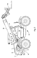
- FIG. 2 shows a mobile telescopic loader 82 with a telescopically extendable arm 86 pivotably articulated on a housing 84 or frame of the telescopic handler 82.
- a hydraulic cylinder 26 for lifting and lowering the arm 86 is arranged between the arm 86 and the housing 84.
- the hydraulic cylinder 26 is pivoted to a first and a second bearing 88, 90, wherein the piston rod side 92 is hinged to the second bearing point 90 on the arm 86 and the piston bottom side 94 at the first bearing 88 on the housing 84.
- the hydraulic tank 20, the pump 18 and the control unit 12 are positioned on or in the housing 84 and connected to each other via hydraulic lines 14, 16, 96. Further the supply lines 22, 24 between control unit 12 and hydraulic cylinder 26 in Fig. 2 can be seen.
- the pipe burst protection device 32 and the switching valve 52 are located in a common valve block directly on the hydraulic cylinder 26.
- the hydraulic accumulator 48 is preferably also disposed directly on the hydraulic cylinder 26, so that between the common valve block and the hydraulic accumulator 48, the hydraulic line 46 can be formed as a rigid connection, which does not require a separate breakaway device. Via a control not shown, control or switching signals are generated with which the control unit 12 and the switching valve 52 (see FIG. 1) are controlled or switched.
- the hydraulic cylinder 26 can be operated such that the boom 86 can be raised, held, lowered or resiliently held.
- activated suspension and in spring position ensures that during excitation, for example, by the chassis of the telehandler 82, shock-like acceleration due to a free swing of the boom 86 are damped, so that there is an increase in ride comfort, especially if with a Work tool 98 loads are absorbed and moved.
- suspension system can be applied to other vehicles, such as wheel loaders or front loaders or to excavators or cranes that hydraulically have actuated components which can be raised or lowered and in which a suspension seems useful.
Description
Die Erfindung betrifft ein hydraulisches passives Federungssystem, mit einem eine erste und eine zweite Kammer aufweisenden Hydraulikzylinder, einem Hydrauliktank, einem eine Hydraulikflüssigkeit fördernden Fördermittel, einem Hydraulikspeicher, einer zwischen Hydraulikspeicher und ersten Kammer angeordneten Hydraulikleitung, einem in der Hydraulikleitung angeordneten Schaltventil, einer ersten Versorgungsleitung für die erste Kammer, einer zweiten Versorgungsleitung für die zweite Kammer, einer in der ersten Versorgungsleitung angeordneten Rohrbruchsicherungseinrichtung und einem Steuergerät mit wenigstens drei Schaltstellungen, welche eine Hebestellung, eine Senkstellung und eine Neutralstellung für den Hydraulikzylinder umfassen.The invention relates to a hydraulic passive suspension system comprising a hydraulic cylinder having a first and a second chamber, a hydraulic tank, a hydraulic fluid conveying means, a hydraulic accumulator, a hydraulic line arranged between hydraulic accumulator and first chamber, a switching valve arranged in the hydraulic line, a first supply line for the first chamber, a second supply line for the second chamber, a pipe rupture protection device arranged in the first supply line and a control device with at least three switch positions, which comprise a lifting position, a lowered position and a neutral position for the hydraulic cylinder.
Bei landwirtschaftlichen Maschinen, wie z.B. Teleskoplader, Radlader oder Frontlader an Traktoren, ist es bekannt, ein hydraulisches Federungssystem einzusetzen, das den Ausleger bzw. die Schwinge abfedert, um einen insgesamt am Fahrzeug verbesserten Federungskomfort, insbesondere während der Fahrt, zu erzielen. Hierbei wird mittels einer geeigneten hydraulischen Anordnung von Ventilen die Hubseite eines Hydraulikzylinders mit einem Hydrospeicher verbunden um eine Federung durch den Hydrospeicher zu bewirken. Ferner wird die Senkseite des Hydraulikzylinders mit einem Hydrauliktank verbunden, um zum einen eine Kavitation auf der Senkseite zu vermeiden und zum anderen ein freies Bewegen der Kolbenstange während des Federungsvorganges zu ermöglichen. Zur Erhöhung der Sicherheit gegen ein plötzliches Absinken des Auslegers bzw. der Schwinge können diese Federungssysteme, zur Absicherung des Hydraulikzylinders gegen Schlauchbrüche, mit Lasthalteventilen versehen sein. Zum Absenken des Hydraulikzylinders ist es dann jedoch erforderlich die Tankverbindung der Senkseite des Hydraulikzylinders zu schließen, damit sich ein erforderlicher Druck aufbauen kann, um das Lasthalteventil zu öffnen. Erst wenn das Lasthalteventil geöffnet wird, kann Öl aus der Hubseite des Hydraulikzylinders abfließen.In agricultural machines, such as telescopic loader, wheel loader or front loader on tractors, it is known to use a hydraulic suspension system that cushions the boom or the rocker to achieve overall on the vehicle improved suspension comfort, especially while driving. Here, by means of a suitable hydraulic arrangement of valves, the lifting side of a hydraulic cylinder is connected to a hydraulic accumulator to effect a suspension through the hydraulic accumulator. Further, the lowering side of the hydraulic cylinder is connected to a hydraulic tank to prevent on the one hand cavitation on the lower side and on the other to allow free movement of the piston rod during the suspension process. To increase safety against a sudden drop in the boom or the rocker these suspension systems, to protect the hydraulic cylinder against hose breaks, be provided with load-holding valves. However, it is then necessary to lower the hydraulic cylinder Close tank connection of the lower side of the hydraulic cylinder, so that a required pressure can build up to open the load-holding valve. Only when the load-holding valve is opened, oil can flow out of the lift side of the hydraulic cylinder.
Ein derartiges Federungssystem wird in der
Die der Erfindung zugrunde liegende Aufgabe wird darin gesehen, ein hydraulisches passives Federungssystem der eingangs genannten Art zu schaffen, durch die ein Aufwand zur Realisierung der "Absenken-Funktion" reduziert wird. Insbesondere soll eine Fehlschaltung des Federungssystem für die "Absenken-Funktion" bei nicht vorhandener oder defekter Überwachungseinrichtung ausgeschlossen werden.The object underlying the invention is seen to provide a hydraulic passive suspension system of the type mentioned, by which an effort to realize the "lowering function" is reduced. In particular, a malfunction of the suspension system for the "lowering function" is to be excluded in the absence or defective monitoring device.
Die Aufgabe wird erfindungsgemäß durch die Lehre des Patentanspruchs 1 gelöst. Weitere vorteilhafte Ausgestaltungen und Weiterbildungen der Erfindung gehen aus den Unteransprüchen hervor.The object is achieved by the teaching of claim 1. Further advantageous embodiments and modifications of the invention will become apparent from the dependent claims.
Erfindungsgemäß ist ein hydraulisches passives Federungssystem der eingangs genannten Art derart ausgebildet, dass das Steuergerät, eine weitere Schaltstellung aufweist, welche eine Federungsstellung darstellt, in welcher durch das Steuergerät wenigstens die zweite Versorgungsleitung mit dem Tank verbindbar ist und gleichzeitig Verbindungen beider Versorgungsleitungen zum Fördermittel unterbrochen sind. Dadurch, dass das Steuergerät eine vierte Schaltstellung aufweist, kann auf ein zweites Schaltventil zur Verbindung der zweiten Kammer des Hydraulikzylinders mit einem Tank, wie es bei konventionellen Lösungen vorgesehen ist, verzichtet werden. Damit reduziert sich der technische Aufwand erheblich, insbesondere deswegen, weil eine Überwachung der "Absenken-Funktion" für den Hydraulikzylinder entfällt. Somit wird vorzugsweise nur ein Schaltventil verwendet, mit dem lediglich die Hubseite des Hydraulikzylinders mit dem Hydrospeicher verbunden wird.According to the invention, a hydraulic passive suspension system of the type mentioned above is formed such that the control unit has a further switching position, which represents a suspension position, in which at least the second supply line is connected to the tank by the control unit and at the same time connections of both supply lines to the conveyor are interrupted , Characterized in that the control device has a fourth switching position, can be dispensed with a second switching valve for connecting the second chamber of the hydraulic cylinder with a tank, as provided in conventional solutions. This reduces the technical complexity considerably, in particular because a monitoring of the "lowering function" for the hydraulic cylinder is eliminated. Thus, preferably only one switching valve is used, with which only the lifting side of the hydraulic cylinder is connected to the hydraulic accumulator.
Eine erfindungsgemäße vierte Schaltstellung bietet den Vorteil, dass neben einer Hebestellung und einer Senkstellung weiterhin eine Neutralstellung für den Hydraulikzylinder bereitgestellt werden kann, in der beide Versorgungsleitungen geschlossen sind. In der Neutralstellung soll die Verbindung zwischen der Senkseite des Hydraulikzylinders und dem Tank vorzugsweise geschlossen sein, da es Anwendungen mit Radladern, Teleskopladern und auch Frontladern gibt, bei denen ein bestimmter Anpressdruck unter einem am Ausleger befestigten Werkzeug erzeugt werden soll, was bei einer ständigen Verbindung zum Tank nicht möglich wäre und so zu einem Nachteil gegenüber Konkurrenzprodukten führen würde. Es ist daher von Vorteil eine erfindungsgemäße vierte Schaltstellung hinzuzufügen und sowohl die Hebe- und Senkstellung als auch die Neutralstellung bereitzustellen.A fourth shift position according to the invention has the advantage that in addition to a lifting position and a lowered position Furthermore, a neutral position can be provided for the hydraulic cylinder, in which both supply lines are closed. In the neutral position, the connection between the lowering side of the hydraulic cylinder and the tank should preferably be closed, as there are applications with wheel loaders, telehandlers and front loaders in which a certain contact pressure is to be generated under a boom-mounted tool, resulting in a permanent connection to the tank would not be possible and so would lead to a disadvantage compared to competing products. It is therefore advantageous to add a fourth switching position according to the invention and to provide both the lifting and lowering position and the neutral position.
Das Steuergerät kann derart ausgebildet sein, dass als vierte Schaltposition eine sogenannte Schwimmstellung geschaltet wird. In der Schwimmstellung ist die erste Versorgungsleitung mit der zweiten Versorgungsleitung zusammengeschaltet und beide Versorgungsleitungen mit dem Tank verbunden, wobei der zweite Eingang zum Steuergerät geschlossen ist, so dass keine Versorgung seitens des Fördermittels erfolgt. Eine Schwimmstellung als vierte Schaltstellung ist nicht zwingend erforderlich, es ist ausreichend, wenn die vierte Schaltstellung lediglich die zweite Kammer des Hydraulikzylinders mit dem Tank verbindet.The control unit may be designed such that a so-called floating position is switched as fourth switching position. In the floating position, the first supply line is connected to the second supply line and both supply lines connected to the tank, wherein the second input to the control unit is closed, so that no supply takes place by the conveyor. A floating position as the fourth switching position is not mandatory, it is sufficient if the fourth switching position connects only the second chamber of the hydraulic cylinder with the tank.
In der Federungsstellung verbindet das Steuergerät die zweite Versorgungsleitung bzw. die zweite und die erste Versorgungsleitung unmittelbar mit Tank, d.h. es werden keine weiteren Ventile oder Mittel benötigt (außer einer Verbindungsleitung vom Steuergerät zum Tank). Das Steuergerät kann manuell oder auch elektrisch betätigbar ausgebildet sein, wobei selbstverständlich auch noch andere Methoden denkbar sind, beispielsweise pneumatische oder hydraulische Methoden, die jedoch nicht näher erläutert werden sollen.In the suspension position, the control unit connects the second supply line or the second and the first supply line directly to the tank, ie no further valves or means are required (except for a connecting line from the control unit to the tank). The control unit can be designed manually or electrically actuated, Of course, other methods are conceivable, for example, pneumatic or hydraulic methods, which should not be explained in detail.
Das Schaltventil weist vorzugsweise eine Schließstellung und eine Öffnungsstellung auf, wobei das Schaltventil in der Schließstellung in eine oder in beide Fließrichtungen schließt, jedoch in der Öffnungsstellung in beide Fließrichtungen öffnet, so dass eine Federungsfunktion in Verbindung mit dem Hydraulikspeicher eintritt. Das Schaltventil kann derart ausgebildet sein, dass in der Schließstellung Hydraulikflüssigkeit vom Hydraulikzylinder zum Hydrospeicher durchströmen kann, so dass der Hydrospeicher immer mit dem höchsten Lastdruck vorgespannt wird, der während eines Arbeitszyklus auftritt. Ferner kann das Schaltventil auch derart ausgebildet sein, dass es in der Schließstellung in die entgegengesetzte Richtung hin abdichtet oder auch in beide Richtungen. Des Weiteren sind auch Umgehungen des Schaltventils mittels Rückschlagventilen und Blenden denkbar, um den Hydrospeicher aufzuladen. Das Schaltventil ist vorzugsweise elektrisch betätigbar. Es ist selbstverständlich auch denkbar, dass andere Betätigungsarten des Schaltventils eingesetzt werden, beispielsweise eine manuelle, pneumatische oder hydraulische Betätigung.The switching valve preferably has a closed position and an open position, wherein the switching valve closes in the closed position in one or both flow directions, but opens in the open position in both flow directions, so that a suspension function occurs in connection with the hydraulic accumulator. The switching valve may be designed such that in the closed position hydraulic fluid can flow from the hydraulic cylinder to the hydraulic accumulator, so that the hydraulic accumulator is always biased with the highest load pressure that occurs during a work cycle. Furthermore, the switching valve can also be designed such that it seals in the closed position in the opposite direction or in both directions. Furthermore, bypassing the switching valve by means of check valves and orifices are also conceivable in order to charge the hydraulic accumulator. The switching valve is preferably electrically actuated. It is of course also conceivable that other types of actuation of the switching valve are used, for example, a manual, pneumatic or hydraulic actuation.
Soll nun die Federung aktiviert werden, was mittels eines Schalters geschehen kann, den der Bediener in der Kabine des Fahrzeugs betätigt, oder beispielsweise auch durch ein Geschwindigkeitssignal, so wird das Schaltventil in seine Öffnungsstellung und das Steuergerät in seine vierte Schaltstellung geschaltet, um die erste Kammer des Hydraulikzylinders mit dem Tank zu verbinden. Während einer Anregung durch das Fahrwerk der Arbeitsmaschine können stoßartige Beschleunigungen durch das freie Schwingen des Auslegers bzw. der Schwinge abgedämpft werden, so dass eine Steigerung des Fahrkomforts erzielbar ist.If now the suspension should be activated, which can be done by means of a switch that the operator operates in the cabin of the vehicle, or for example by a speed signal, the switching valve is switched to its open position and the control unit in its fourth switching position to the first Chamber of the hydraulic cylinder to connect to the tank. During one Excitation by the chassis of the machine shock-like acceleration can be damped by the free swinging of the boom or the rocker, so that an increase in ride comfort is achieved.
Wird der Ausleger bzw. die Schwinge bei aktivierter Federung abgesenkt, wird durch Verstellen des Steuergerätes in die Senkstellung automatisch die Verbindung der zweiten Kammer des Hydraulikzylinders mit dem Tank geschlossen und Hydraulikflüssigkeit strömt in die zweite Kammer des Hydraulikzylinders, wo jetzt ein ausreichend hoher Druck aufgebaut werden kann, um das Lasthalteventil zu öffnen, was zum Absenken des Auslegers bzw. der Schwinge zwingend erforderlich ist. Bei den marktüblichen Federungssystemen mit Lasthalteventil bzw. mit einer Rohrbruchsicherungseinrichtung wird ein zweites Schaltventil benötigt, welches die für eine Federungsfunktion erforderliche Verbindung zum Tank herstellt und welches geschlossen werden muss, um den erforderlichen Druckaufbau zu gewährleisten.If the boom or the rocker is lowered when the suspension is activated, the connection of the second chamber of the hydraulic cylinder to the tank is automatically closed by adjusting the control unit in the lowering position and hydraulic fluid flows into the second chamber of the hydraulic cylinder, where now a sufficiently high pressure is built up can to open the load-holding valve, which is mandatory for lowering the boom or the rocker. In the usual market suspension systems with load-holding valve or with a pipe rupture device, a second switching valve is required, which produces the required for a suspension function connection to the tank and which must be closed to ensure the required pressure build-up.
Wird der Ausleger bzw. die Schwinge bei aktivierter Federung mit der Hebestellung des Steuergerätes angehoben, ist automatisch die zweite Kammer des Hydraulikzylinders mit dem Tank verbunden, damit die durch den Hebevorgang verdrängte Hydraulikflüssigkeit aus dem Hydraulikzylinder zum Tank strömen kann. Sollte während des Hebevorgangs ein Stoß auf den Ausleger bzw. auf die Schwinge übertragen werden, kann dieser bzw. diese ohne der Gefahr einer Kavitation einfedern, da die zweite Kammer zum Tank hin entlastet ist.If the boom or the rocker is raised with the suspension of the control unit with the suspension activated, the second chamber of the hydraulic cylinder is automatically connected to the tank, so that the hydraulic fluid displaced by the lifting operation can flow from the hydraulic cylinder to the tank. If a shock is transmitted to the boom or the rocker during the lifting process, this or these can deflect without the risk of cavitation, since the second chamber is relieved to the tank.
Lediglich in der Neutralstellung des Steuergerätes muss das Schaltventil, das die erste Kammer mit dem Hydrospeicher verbindet, geschlossen werden, da hier beim Einfedern des Auslegers bzw. der Schwinge die Gefahr besteht, dass in der zweiten Kammer des Hydraulikzylinders ein Unterdruck (Kavitation) entsteht, der die Dichtungen des Hydraulikzylinders beschädigen kann. Damit es zu einem problemlosen Bedienen des Auslegers bzw. der Schwinge kommen kann, wird das Schaltventil vorzugsweise immer dann automatisch geschlossen, d. h. in Schließstellung gebracht, wenn sich das Steuergerät in seiner Neutralstellung befindet, während die Federung aktiv ist. Vorzugsweise sind dazu Mittel vorgesehen, mit denen ermittelt wird, ob sich das Ventil in seiner geschlossenen Neutralstellung befindet oder nicht. Dies kann beispielsweise in Form eines Schalters umgesetzt werden, der in Verbindung bzw. in Abhängigkeit von der Neutralstellung am Steuergerät geschaltet wird. Bei elektrohydraulisch angesteuerten Steuergeräten ist ein derartiger Schalter meist nicht erforderlich, da diese Aufgabe von der Software einer elektronischen Steuereinheit übernommen werden kann. Es ist darüber hinaus auch unerheblich, wie und wo die Schaltstellung des Steuergerätes erfasst wird, da lediglich das Ergebnis als solches von Interesse ist. Ein oben genannter Schalter kann an einem Joystick, an einer Betätigungsmechanik inkl. Seilzug oder auch direkt am Steuergerät angebracht werden. Denkbar ist hier auch ein Sensor, der ein proportionales Signal aufnimmt, welches in einer geeigneten Auswerteelektronik in ein elektrisches Signal umgewandelt wird, welches das Schaltventil in Schließstellung schaltet. Auch wäre es denkbar, einen Druckschalter oder Drucksensor zu verwenden, der den Vorsteuerdruck, der von einem hydraulischen Joystick als Stellsignal an das Steuergerät geschickt wird, bestimmt. Es ergeben sich somit eine Vielzahl von Möglichkeiten die Schaltposition des Steuergeräts zu bestimmen.Only in the neutral position of the control unit must the switching valve, which is the first chamber with the hydraulic accumulator connects, be closed, since there is the risk during compression of the jib or the rocker that in the second chamber of the hydraulic cylinder, a negative pressure (cavitation) is formed, which can damage the seals of the hydraulic cylinder. So that it can come to a trouble-free operation of the boom or the rocker, the switching valve is preferably always closed automatically, ie brought into the closed position when the controller is in its neutral position, while the suspension is active. Preferably, means are provided for determining whether or not the valve is in its closed neutral position. This can be implemented, for example, in the form of a switch, which is switched in conjunction or in dependence on the neutral position on the control unit. In electro-hydraulically controlled control devices, such a switch is usually not required, since this task can be taken over by the software of an electronic control unit. It is also irrelevant how and where the switching position of the control unit is detected, since only the result as such is of interest. A switch mentioned above can be attached to a joystick, to an actuation mechanism incl. Cable or directly to the control unit. Also conceivable here is a sensor which receives a proportional signal, which is converted into a suitable evaluation in an electrical signal, which switches the switching valve in the closed position. It would also be conceivable to use a pressure switch or pressure sensor, which determines the pilot pressure, which is sent by a hydraulic joystick as a control signal to the control unit. It thus results a variety of ways to determine the switching position of the controller.
Um zu ermöglichen, dass bei aktiver Federung die Neutralstellung passierbar ist, ohne das sofort in die Schließstellung des Schaltventils geschaltet wird, ist in einer bevorzugten Ausgestaltung der Erfindung ein Zeitverzögerungselement vorgesehen. Ein Passieren der Neutralstellung kann beispielsweise erforderlich sein, wenn die Neutralstellung am Steuergerät direkt zwischen der Hebe- und Senkstellung angeordnet ist und von einer Hebestellung direkt in eine Senkstellung geschaltet werden soll. Das Zeitverzögerungselement sieht vor, dass beim einfachen Passieren der Neutralstellung das Schalten des Schaltventils nicht vorgenommen wird. Erst wenn eine voreinstellbare Verweilzeit in Neutralstellung erreicht ist, wird das Schaltventil in die Schließstellung gebracht.In order to make it possible for the neutral position to be passable when the suspension is active without being immediately switched to the closed position of the switching valve, a time delay element is provided in a preferred embodiment of the invention. A passing of the neutral position, for example, may be required if the neutral position is located on the control unit directly between the lifting and lowering position and should be switched from a lifting position directly into a lowered position. The time delay element provides that the simple switching of the neutral position, the switching of the switching valve is not made. Only when a presettable residence time is reached in neutral position, the switching valve is brought into the closed position.
Bei einem elektronisch oder elektrohydraulisch angesteuerten Steuergerät kann beispielsweise in der Steuersoftware auch berücksichtigt werden, dass beispielsweise bei nicht betätigtem Joystick das Steuergerät bei aktivierter Federung grundsätzlich nicht in seine Neutralstellung sondern in die vierte Schaltstellung verfahren wird. Ebenfalls wäre es auch denkbar, dass wie bei einigen Radladern üblich, während des Hebens und Senkens des Auslegers bzw. der Schwinge die Federung grundsätzlich deaktiviert wird. Als eine sehr vereinfachte Version des Systems wäre es auch denkbar, dass die Federung ausschließlich dann aktiv ist, wenn sich das Steuergerät in seiner vierten Schaltstellung befindet. Auf diese Art ließe sich der elektronische Aufwand erheblich verringern, da lediglich ein Schalter benötigt wird, der das Schaltventil öffnet oder schließt.In an electronically or electrohydraulically controlled control unit, for example, in the control software also be taken into account that, for example, when the joystick is not actuated, the control unit is basically not moved in its neutral position but in the fourth switching position with activated suspension. It would also be conceivable that, as is usual with some wheel loaders, the suspension is basically deactivated during the raising and lowering of the jib or the rocker. As a very simplified version of the system, it would also be conceivable that the suspension is only active when the controller is in its fourth shift position. In this way, the electronic effort could be considerable reduce, since only one switch is needed, which opens or closes the switching valve.
Das Steuergerät ist vorzugsweise als Schieberventil ausgebildet, welches vier Schaltstellungen mit jeweils zwei Ein- und Ausgängen aufweist. In den einzelnen Stellungen werden die Versorgungsleitungen auf unterschiedliche Weise entsprechend den Stellfunktion (Heben, Senken, Neutralstellung (Halten) und Federung) des Steuergeräts mit dem Fördermittel oder mit dem Tank verbunden bzw. geschlossen.The control unit is preferably designed as a slide valve, which has four switching positions, each with two inputs and outputs. In the individual positions, the supply lines are connected or closed in different ways in accordance with the actuating function (lifting, lowering, neutral position (holding) and suspension) of the control unit with the conveying means or with the tank.
Die Rohrbruchsicherungseinrichtung umfasst vorzugsweise ein in Richtung des Steuergeräts schließendes Rückschlagventil und ein Druckbegrenzungsventil, wobei das Druckbegrenzungsventil durch in den Verbindungsleitungen vorherrschenden Drücken ansteuerbar ist. Die Ansteuerung erfolgt durch Pilotdruckleitungen, welche von dem Druckbegrenzungsventil in die erste und in die zweite Versorgungsleitung führen. Das Rückschlagventil ist in einer das Druckbegrenzungsventil umgehenden Bypass-Leitung angeordnet, wobei das Rückschlagventil in Richtung der ersten Kammer öffnet. Andere Möglichkeiten zur Rohrbruchsicherung sind ebenfalls denkbar. So können beispielsweise auch Duckschalter verwendet werden, die bei Druckabfall, ein Schaltventil betätigen.The pipe rupture protection device preferably comprises a check valve closing in the direction of the control device and a pressure limiting valve, wherein the pressure limiting valve can be activated by prevailing pressures in the connecting lines. The control is carried out by pilot pressure lines, which lead from the pressure relief valve in the first and in the second supply line. The check valve is arranged in a bypass line bypassing the pressure limiting valve, wherein the check valve opens in the direction of the first chamber. Other possibilities for pipe burst protection are also conceivable. For example, it is also possible to use duck switches which actuate a switching valve when the pressure drops.
Im Vergleich zu üblichen Federungssystemen ergibt sich ein kostengünstigere hydraulische Anordnung, da das erforderliche zweite Schaltventil samt dessen Verschlauchung auf der Seite der zweite Kammer des Hydraulikzylinders entfällt und statt dessen ein handelsübliches Schieberventil mit Schwimmstellungsfunktion verwendet werden kann. Durch den Wegfall eines zweiten Schaltventils wird auch die Anzahl möglicher Fehlerquellen verringert, da eine Komponente weniger eingesetzt wird. Des Weiteren ergeben sich günstigere gestalterische Möglichkeiten, da weniger Bauraum benötigt wird.Compared to conventional suspension systems results in a more cost-effective hydraulic arrangement, since the required second switching valve together with its tubing omitted on the side of the second chamber of the hydraulic cylinder and instead a commercial slide valve with floating position function can be used. By eliminating a second switching valve and the number possible sources of error because one less component is used. Furthermore, there are more favorable design options, since less space is needed.
Besonders bei Traktoren mit Frontlader ist es üblich, dass die hydraulische und elektrische Verbindung zwischen Frontlader und Traktor mittels sogenannter Multikuppler sichergestellt wird, die ein schnelles und einfaches Verbinden und Trennen ermöglichen. Durch die Verwendung einer erfindungsgemäßen hydraulischen Anordnung können diese Multikuppler beibehalten werden, da kein zusätzlicher Schlauch zur Verbindung der Senkseite des Hydraulikzylinders mit dem Tank erforderlich ist. Aufgrund der internen Verbindung des Steuergerätes in seiner vierten Schaltposition mit dem Tank, kann die zweite Kammer des Hydraulikzylinders mittels des bereits vorhandenen zweiten Versorgungsschlauches versorgt werden.Especially with tractors with front loader, it is common that the hydraulic and electrical connection between front loader and tractor is ensured by means of so-called multi-couplers, which allow a quick and easy connection and disconnection. By using a hydraulic arrangement according to the invention, these multi-couplers can be maintained, since no additional hose for connecting the lowering side of the hydraulic cylinder is required with the tank. Due to the internal connection of the control unit in its fourth switching position with the tank, the second chamber of the hydraulic cylinder can be supplied by means of the already existing second supply hose.
Anhand der Zeichnung, die ein Ausführungsbeispiel der Erfindung zeigt, werden nachfolgend die Erfindung sowie weitere Vorteile und vorteilhafte Weiterbildungen und Ausgestaltungen der Erfindung näher beschrieben und erläutert.Reference to the drawing, which shows an embodiment of the invention, the invention and further advantages and advantageous developments and refinements of the invention are described and explained in more detail below.
Es zeigt:
- Fig. 1
- eine hydraulische Anordnung für ein Federungssystem eines Hydraulikzylinders und
- Fig. 2
- eine schematische Darstellung eines Teleskopladers mit einer hydraulischen Anordnung aus Figur 1.
- Fig. 1
- a hydraulic arrangement for a suspension system of a hydraulic cylinder and
- Fig. 2
- a schematic representation of a telescopic loader with a hydraulic arrangement of Figure 1.
Eine in Fig. 1 dargestellte hydraulische Anordnung 10 zeigt ein erfindungsgemäßes Ausführungsbeispiel zur Realisierung einer Federung. Die hydraulische Anordnung 10 enthält ein schaltbares Steuergerät 12, beispielsweise ein Schieberventil, welches über Hydraulikleitungen 14, 16 mit einer Pumpe 18 und einem Hydrauliktank 20 verbunden ist, wobei das Steuergerät 12 in vier Betriebsstellungen, Hebe-, Neutral-, Senk- und Federungsstellung, schaltbar ist. Das Schalten des Steuergeräts 12 erfolgt vorzugsweise handgesteuert, kann aber auch elektrisch, hydraulisch oder pneumatisch erfolgen.An illustrated in Fig. 1
Über eine erste und zweite Versorgungsleitung 22, 24 ist das Steuergerät 12 mit einem Hydraulikzylinder 26 verbunden, wobei die erste Versorgungsleitung 22 in eine erste Kammer 28 des Hydraulikzylinders 26 und die zweite Versorgungsleitung 24 in eine zweite Kammer 30 des Hydraulikzylinders 26 führt. Ein Kolben 29 trennt die beiden Kammern 26, 28 voneinander. Die erste Kammer 28 des Hydraulikzylinders 26 stellt die kolbenbodenseitige bzw. hubseitige Kammer dar, wohingegen die zweite Kammer 30 die kolbenstangenseitige bzw. senkseitige Kammer des Hydraulikzylinders darstellt.Via a first and
In der ersten Versorgungsleitung 22 ist eine Lasthalteventilanordnung oder Rohrbruchsicherungseinrichtung 32 vorgesehen. Die Rohrbruchsicherungseinrichtung 32 enthält ein druck- und federgesteuertes Druckbegrenzungsventil 34, sowie ein zur Hydraulikzylinderseite öffnendes Rückschlagventil 36, welches über eine Bypassleitung 38 parallel zum Druckbegrenzungsventil 34 angeordnet ist. Über eine erste Druckleitung 40 ist eine Druckverbindung vom Druckbegrenzungsventil 34 zum hydraulikzylinderseitigen Abschnitt der ersten Versorgungsleitung 22 hergestellt. Über eine zweite Druckleitung 42 ist eine weitere Druckverbindung vom Druckbegrenzungsventil 34 zur zweiten Versorgungsleitung 24 hergestellt. Des Weiteren hält eine Stellfeder 44 das Druckbegrenzungsventil 34 in Schließstellung.In the
Eine Hydraulikleitung 46 verbindet die erste Kammer 28 bzw. die erste Versorgungsleitung 22 mit einem Hydraulikspeicher 48, wobei das nicht mit dem Hydraulikspeicher 48 verbundene Ende 50 der Hydraulikleitung 46 zwischen der ersten Kammer 28 und der Rohrbruchsicherungseinrichtung 32 angeordnet ist.A
In der Hydraulikleitung 46 ist ein Schaltventil 52 angeordnet. Das Schaltventil 52 stellt ein elektrisch schaltbares Sitzventil dar, welches über eine Stellfeder 54 in Schließstellung gehalten wird und über eine Magnetspule 56 in eine Öffnungsstellung gebracht werden kann. Das Schaltventil 52 dichtet dabei in Schließstellung in Richtung des Hydraulikspeichers 48 ab. Hierbei kann das Schaltventil auch derart ausgebildet sein, dass es in beide Richtungen leckagefrei abdichtet. In der Öffnungsstellung ist zur Herstellung einer Federungsfunktion zwischen Hydraulikzylinder 26 und Hydraulikspeicher 48 ein hydraulischer Fluss in beide Richtungen gewährleistet.In the
Die einzelnen Betriebszustände können nun wie folgt über das Steuergerät 12 sowie über die Schaltventil 52 angesteuert werden. Wie in Fig. 1 dargestellt, wird das Steuergerät 12 durch Stellfedern 60, 62 in Neutralstellung gehalten. Das Schaltventil 52 befindet sich in einer Schließstellung. Über ein Steuersignal oder, wie in Figur 1 dargestellt, durch manuelle Betätigung wird das Steuergerät 12 mittels einer Betätigungsvorrichtung 58 aus der Neutralstellung heraus in die Hebe-, Senk- oder Federungsstellung gebracht. Dabei kann es sich um eine manuelle, elektrische, hydraulische oder pneumatische Betätigungsvorrichtung 58 handeln.The individual operating states can now be controlled as follows via the
Anhand eines mit der Betätigungsvorrichtung 58 verbundenen Schalters oder Sensors 64 wird die Neutralstellung des Steuergeräts 12 detektiert und ein Signal an eine Steuereinheit 66 gesendet. Die Steuereinheit 66 ist mit dem Schaltventil 52 verbunden und hält bzw. bringt das Schaltventil 52 in Schließstellung, wenn sich das Steuergerät 12 in Neutralstellung befindet. Vorzugsweise ist die Steuereinheit 66 mit einem Zeitverzögerungsglied versehen, welches bewirkt, dass erst nach einer voreinstellbaren Verweilzeit des Steuergeräts 12 in der Neutralstellung die Steuereinheit 66 das Schaltventil 52 in Schließstellung bringt. Dadurch wird gewährleistet, dass nicht bei jedem Schaltvorgang des Steuergeräts 12, wenn nur über die Neutralstellung hinweg geschaltet wird, die Steuereinheit 66 das Schaltventil 52 schließt. Das Schaltventil 52 wird nur dann in Schließstellung gebracht, wenn das Steuergerät 12 tatsächlich in die Neutralstellung geschaltet wird.Based on a connected to the
In der Hebestellung wird die Verbindung der ersten Versorgungsleitung 22 mit der Pumpe 18 und die Verbindung der zweiten Versorgungsleitung 24 mit dem Hydrauliktank 20 hergestellt. Die mit dem Hydrauliktank 20 verbundene Pumpe 18 befüllt über die erste Versorgungsleitung 22 und über das Rückschlagventil 36 der Rohrbruchsicherungseinrichtung 32 (das Druckbegrenzungsventil 34 der Lasthalteanordnung 32 befindet sich in Schließstellung) die erste Kammer 28 des Hydraulikzylinders 26. In Folge dessen bewegt sich der Kolben 29 in Richtung der zweiten Kammer 30 und drückt das dort vorhandene Öl durch die zweite Versorgungsleitung 24 heraus in den Hydrauliktank 20. Wird nun wieder in die Neutralstellung geschaltet, so unterbricht das Steuergerät 12 die Verbindungen zur Pumpe 18 und zum Hydrauliktank 20, so dass der Druck in den beiden Kammern 28, 30 des Hydraulikzylinders 26 beibehalten und die Bewegung des Kolbens 29 aufgehoben wird. Der Kolben 29 bleibt stehen.In the lifting position, the connection of the
In der Senkstellung wird die Verbindung der ersten Versorgungsleitung 22 mit dem Hydrauliktank 20 und die Verbindung der zweiten Versorgungsleitung 24 mit der Pumpe 18 hergestellt. Die Pumpe fördert Öl in die zweite Kammer 30 des Hydraulikzylinders 26, wobei der sich in der zweiten Versorgungsleitung 24 aufbauende Druck das Druckbegrenzungsventil 34 über die zweite Druckleitung 42 der Rohrbruchsicherungseinrichtung 32 öffnet. Gleichzeitig wird der Kolben 29 in Richtung der ersten Kammer 28 bewegt, so dass das aus der ersten Kammer 28 strömende Öl über die erste Versorgungsleitung 22 und über das geöffnete Druckbegrenzungsventil 34 in den Hydrauliktank 20 gelangt.In the lowering position, the connection of the
Die Rohrbruchsicherungseinrichtung 32 stellt somit sicher, dass der Hydraulikzylinder 26 in Neutralstellung seine Position beibehält bzw. in Hebe- und Neutralstellung kein Öl aus der druckbeaufschlagten ersten Kammer 28 entweichen und dass in Senkstellung das Öl aus der ersten Kammer 28 über das geöffnete Druckbegrenzungsventil 34 abfließen kann. Um dies zu gewährleisten sollte bzw. muss die Rohrbruchsicherungseinrichtung 32 sinnvoller Weise wie abgebildet auf der Hubseite des Hydraulikzylinders 26 angeordnet sein, wobei die Hubseite die Seite des Hydraulkzylinders 26 ist, in der ein Druck zum Heben einer Last aufgebaut wird. In den hier dargestellten Ausführungsbeispielen ist die Hubseite die erste Kammer 28 des Hydraulikzylinders 26, wobei durch Umdrehen des Hydraulikzylinders 26 auch die zweite Kammer 30 als Hubseite dienen könnte. Die erste Druckleitung 40 stellt eine Überlastsicherung dar, so dass bei zu hohen Betriebsdrücken in der ersten Kammer 28 des Hydraulikzylinders 26, die beispielsweise durch zu hohe Traglasten entstehen können, in der ersten Druckleitung 40 ein Grenzdruck erreicht wird, der das Druckbegrenzungsventil 34 zum Druckabbau öffnet.The
In der Federungsstellung, die in Figur 1 am Steuergerät 12 als unterste Stellung dargestellt ist, wird die Verbindung der zweiten Versorgungsleitung 24 mit dem Hydrauliktank 20 hergestellt. Die Verbindung der ersten Versorgungsleitung 22 zur Pumpe 18 oder zum Hydrauliktank 20 wird geschlossen bzw. die Verbindung bleibt geschlossen, wenn aus der Neutralstellung heraus in die Federungsstellung geschaltet wird. Als alternative Lösung kann in der Federungsstellung auch eine Schwimmstellung geschaltet werden. Bei einer derartigen Schwimmstellung wird dann die erste Versorgungsleitung 22 durch das Steuergerät 12 mit der zweiten Versorgungsleitung 24 verbunden, wobei beide Versorgungsleitungen 22, 24 mit dem Hydrauliktank 20 verbunden und der Eingang am Steuergerät, an dem die Pumpe 18 angeschlossen ist, geschlossen werden. Solange das Schaltventil 52 in Schließstellung ist, d.h. solange der Hydraulikspeicher 48 von dem Hydraulikzylinder 26 getrennt ist und dadurch auch die Federung deaktiviert ist, kann sich der Kolben 29 in der Federungsstellung nur in Richtung der zweiten Kammer 30 bewegen. Erst durch Aktivierung der Federung, d.h. durch Hinzuschalten des Hydraulikspeichers 48 kann sich der Kolben 29 federnd, d.h in beide Richtungen verfahrend, bewegen. Die Aktivierung der Federung erfolgt über einen Aktivierungsschalter 68, der ein Aktivierungssignal an die Steuereinheit 66 abgibt, woraufhin diese das Schaltventil 52 in Öffnungsstellung bringt. Alternativ könnte die Aktivierung der Federung auch automatisch erfolgen, indem ein Aktivierungssignal erzeugt wird, sobald das Steuergerät 12 in die vierte Schaltstellung geschaltet wird.In the suspension position, which is shown in Figure 1 on the
Für die Öffnungsstellung des Schaltventils 52, d.h. für die aktivierte Federung ergeben sich entsprechend der verschiedenen Schaltstellungen des Steuergeräts 12 folgende Zustände:For the open position of the switching
In der Senkstellung (oberste Schaltstellung des Steuergeräts aus Figur 1) wird die erste Versorgungsleitung 22 mit dem Hydrauliktank 20 und die zweite Versorgungsleitung 24 mit der Pumpe verbunden. In der zweiten Versorgungsleitung 24 bzw. in der zweiten Kammer 30 baut sich ein entsprechender Druck auf, durch den das Druckbegrenzungsventil 34 über die Druckleitung 42 geöffnet wird, so dass Öl aus der ersten Kammer 28 über die erste Versorgungsleitung 22 in den Hydrauliktank 20 abfließen kann. Gleichzeitig kann der Kolben 29 federnde Bewegungen ausführen, da eine Verbindung zum Hydraulikspeicher 48 auf der Hubseite und eine Verbindung auf der Senkseite zum Hydrauliktank 20 hergestellt ist.In the lowered position (top switching position of the control unit of Figure 1), the
In der Neutralstellung (von oben zweite Schaltstellung des Steuergeräts 12 aus Figur 1) werden alle Ein- und Ausgänge am Steuergerät 12 geschlossen, d. h. es kann kein Öl durch die Versorgungsleitungen 22, 24 fließen. Falls es in dieser Stellung zu einem Einfedern des Kolbens 29 kommen würde, bestände die Gefahr einer Kavitationswirkung in der zweiten Kammer 30 des Hydraulikzylinders 26, wodurch Dichtungen im Hydraulikzylinder 26 beschädigt werden könnten. Um dieses zu verhindern signalisiert der Schalter bzw. Sensor 64 ein Signal, welches von der Steuereinheit 66 aufgenommen wird. Die Steuereinheit 66 erzeugt daraufhin unter Berücksichtigung einer Zeitverzögerung, zur Bestätigung einer Verweilzeit in der Neutralstellung, ein Schließsignal für das Schaltventil 52. Sobald das Schaltventil 52 geschlossen ist, kann der Kolben 29 keine Bewegungen mehr ausführen, da alle Leitungen 22, 24, 46 geschlossen sind. Sobald das Steuergerät 12 in eine andere Stellung geschaltet wird, gibt der Sensor 64 ein Signal zum Öffnen des Schaltventils 52 frei. Das Signal des Sensors 64 ist somit dem Aktivierungssignal des Aktivierungsschalters 68 in der Schaltlogik der Steuereinheit 66 übergeordnet, damit trotz eines Öffnungssignals vom Aktivierungsschalter 68 das Schaltventil 52 durch ein Schließsignal des Sensors 64 geschlossen werden kann.In the neutral position (from the top second switching position of the
In der Hebestellung (von oben dritte Schaltstellung des Steuergeräts 12 aus Figur 1) wird die erste Versorgungsleitung 22 mit der Pumpe 18 und die zweite Versorgungsleitung 24 mit dem Hydrauliktank 20 verbunden. In der ersten Versorgungsleitung 22 bzw. in der ersten Kammer 28 baut sich ein entsprechender Druck auf, durch den der Kolben 29 angehoben wird, so dass Öl aus der zweiten Kammer 30 über die zweite Versorgungsleitung 24 in den Hydrauliktank 20 abfließen kann. Gleichzeitig kann der Kolben 29 federnde Bewegungen ausführen, da eine Verbindung zum Hydraulikspeicher 48 auf der Hubseite und eine Verbindung auf der Senkseite zum Hydrauliktank 20 hergestellt ist.
Sollte während eines Senk- oder Hebevorgangs ein Stoß auf den Kolben 29 übertragen werden, kann dieser ohne Gefahr der Kavitation einfedern, da die Senkseite zum Hydrauliktank 20 hin entlastet ist.In the lifting position (from the top third switching position of the
If a shock is transmitted to the
In der Federungsstellung (unterste Schaltstellung des Steuergeräts 12 aus Figur 1) wird die erste Versorgungsleitung 22 geschlossen und die zweite Versorgungsleitung 24 mit dem Hydrauliktank 20 verbunden. Der Kolben 29 kann in dieser Stellung frei federn. Bewegt er sich durch einen auf ihn übertragenden Stoß abwärts, wird das Öl aus der ersten Kammer 28 in den Hydraulikspeicher 48 gedrängt. Der sich im Hydraulikspeicher 48 aufbauende Druck lässt das Öl wieder zurück in die erste Kammer 28 strömen, so dass der Kolben 29 sich wieder aufwärts bewegt. Diese federnde Bewegung wiederholt sich gegebenenfalls, bis der Stoß vollständig kompensiert wurde. Des Weiteren kann vorgesehen sein, dass sobald das Steuergerät 12 aus der Federungsstellung heraus in eine andere Stellung bewegt bzw. geschaltet wird, anhand des Sensors 64 in der Steuereinheit 66 ein Deaktivierungssignal für die Federung generiert und dadurch das Schaltventil 52 durch ein Schließsignal geschlossen wird.In the suspension position (lowermost switching position of the
Eine Verwendung für die in Fig. 1 dargestellten Ausführungsbeispiele wird in Fig. 2 verdeutlicht. Fig. 2 zeigt einen fahrbaren Teleskoplader 82 mit einem an einem Gehäuse 84 bzw. Rahmen des Teleskopladers 82 schwenkbar angelenkten, teleskopartig ausfahrbaren, Ausleger 86. Zwischen Ausleger 86 und Gehäuse 84 ist ein Hydraulikzylinder 26 zum Heben und Senken des Auslegers 86 angeordnet. Der Hydraulikzylinder 26 ist dabei an einer ersten und einer zweiten Lagerstelle 88, 90 schwenkbar angelenkt, wobei die Kolbenstangenseite 92 an der zweiten Lagerstelle 90 am Ausleger 86 und die Kolbenbodenseite 94 an der ersten Lagerstelle 88 am Gehäuse 84 angelenkt ist. Des Weiteren sind der Hydrauliktank 20, die Pumpe 18 sowie das Steuergerät 12 am bzw. im Gehäuse 84 positioniert und über Hydraulikleitungen 14, 16, 96 miteinander verbunden. Ferner sind die Versorgungsleitungen 22, 24 zwischen Steuergerät 12 und Hydraulikzylinder 26 in Fig. 2 zu sehen. Die Rohrbruchsicherungseinrichtung 32 sowie das Schaltventil 52 befinden sich in einem gemeinsamen Ventilbaustein direkt am Hydraulikzylinder 26. Der Hydraulikspeicher 48 ist vorzugsweise ebenfalls direkt am Hydraulikzylinder 26 angeordnet, so dass zwischen dem gemeinsamen Ventilbaustein und dem Hydraulikspeicher 48 die Hydraulikleitung 46 als starre Verbindung ausgebildet werden kann, die keine gesonderte Rohbruchsicherungseinrichtung erfordert. Über eine nicht gezeigte Steuerung werden Steuer- bzw. Schaltsignale generiert, mit denen das Steuergerät 12 sowie das Schaltventil 52 (siehe Fig. 1) gesteuert bzw. geschaltet werden. Entsprechend der vorhergehend beschriebenen Schaltstellungen kann der Hydraulikzylinder 26 derart betätigt werden, dass der Ausleger 86 angehoben, festgehalten, abgesenkt oder federnd gehalten werden kann. Bei aktivierter Federung und in Federstellung wird gewährleistet, dass während einer Anregung, beispielsweise durch das Fahrwerk des Teleskopladers 82, stoßartige Beschleunigungen aufgrund eines freien Schwingens des Auslegers 86 abgedämpft werden, so dass es zu einer Steigerung des Fahrkomforts kommt, insbesondere dann, wenn mit einem Arbeitswerkzeug 98 Lasten aufgenommen und verfahren werden.A use for the embodiments shown in Fig. 1 is illustrated in Fig. 2. FIG. 2 shows a mobile
Auch wenn die Erfindung lediglich anhand von zwei Ausführungsbeispielen beschrieben wurde, erschließen sich für den Fachmann im Lichte der vorstehenden Beschreibung sowie der Zeichnung viele verschiedenartige Alternativen, Modifikationen und Varianten, die unter die vorliegende Erfindung fallen. So kann beispielsweise das Federungssystem auch an anderen Fahrzeugen angewendet werden, beispielsweise an Radladern oder Frontladern oder auch an Baggern oder Kränen, die hydraulisch betätigbare Komponenten aufweisen, welche angehoben bzw. abgesenkt werden können und bei denen eine Federung sinnvoll erscheint.Although the invention has been described by way of two embodiments only, many different alternatives, modifications and variations that are within the scope of the present invention will become apparent to those skilled in the art in light of the foregoing description and the drawings. For example, the suspension system can be applied to other vehicles, such as wheel loaders or front loaders or to excavators or cranes that hydraulically have actuated components which can be raised or lowered and in which a suspension seems useful.
Claims (9)
- Hydraulic passive suspension system, with a hydraulic cylinder (26) having a first and a second chamber (28, 30), a hydraulic tank (20), a transport means (18) transporting a hydraulic fluid, a hydraulic accumulator (48), a hydraulic lead (46) arranged between the hydraulic accumulator (48) and the first chamber (28), a switching valve (52) arranged in the hydraulic lead (46), a first supply conduit (22) for the first chamber (28), a second supply conduit (24) for the second chamber (30), a pipe break protection means (32) arranged in the first supply conduit (22), and a control device (12) with at least three switching positions, which include a lifting position, a lowering position and a neutral position for the hydraulic cylinder (26), characterised in that the control device (12) has a further switching position, which represents a suspension position, in which at least the second supply conduit (24) can be connected to the hydraulic tank (20) by the control device (12) and at the same time connections of both supply conduits (22, 24) to the transport means (18) are interrupted.
- Hydraulic passive suspension system according to Claim 1, characterised in that in the suspension position the first and the second connecting conduit (22, 24) can be connected to the hydraulic tank (20) by the control device (12).
- Hydraulic passive suspension system according to Claim 1 or 2, characterised in that the switching valve (52) has a closing position and an opening position.
- Hydraulic passive suspension system according to Claim 3, characterised in that the switching valve (52) in the closing position closes in one or in both directions of flow.
- Hydraulic passive suspension system according to one of the preceding claims, characterised in that means (64, 66) are provided, which bring the switching valve (52) into a closing position when the control device (12) is in the neutral position.
- Hydraulic passive suspension system according to one of the preceding claims, characterised in that means (64, 66) are provided, which bring the switching valve (52) into a closing position when the control device (12) is not in the suspension position.
- Hydraulic passive suspension system according to one of Claims 3 to 5, characterised in that a time delay element is provided, which, when the control device (12) is in neutral position, causes a pre-adjustable time delay for switching the switching valve (52) into the closing position.
- Hydraulic passive suspension system according to one of the preceding claims, characterised in that the control device (12) is a slide valve, which has at least two inlets and two outlets for each switching position.
- Hydraulic passive suspension system according to one of the preceding claims, characterised in that the pipe break protection means (32) comprises a non-return valve (36) closing in the direction of the control device (12) and a pressure control valve (34), wherein the pressure control valve (34) can be actuated by pressures prevailing in the supply conduits (22, 24).
Applications Claiming Priority (2)
| Application Number | Priority Date | Filing Date | Title |
|---|---|---|---|
| DE102004012362A DE102004012362A1 (en) | 2004-03-13 | 2004-03-13 | Hydraulic arrangement |
| DE102004012362 | 2004-03-13 |
Publications (2)
| Publication Number | Publication Date |
|---|---|
| EP1574626A1 EP1574626A1 (en) | 2005-09-14 |
| EP1574626B1 true EP1574626B1 (en) | 2007-08-08 |
Family
ID=34813688
Family Applications (1)
| Application Number | Title | Priority Date | Filing Date |
|---|---|---|---|
| EP05101766A Expired - Fee Related EP1574626B1 (en) | 2004-03-13 | 2005-03-08 | Hydraulic passive suspension system |
Country Status (7)
| Country | Link |
|---|---|
| US (1) | US7140178B2 (en) |
| EP (1) | EP1574626B1 (en) |
| AU (1) | AU2005201082B2 (en) |
| CA (1) | CA2500627C (en) |
| DE (2) | DE102004012362A1 (en) |
| ES (1) | ES2289652T3 (en) |
| NZ (1) | NZ538731A (en) |
Families Citing this family (17)
| Publication number | Priority date | Publication date | Assignee | Title |
|---|---|---|---|---|
| DE102005038333A1 (en) * | 2005-08-11 | 2007-02-15 | Deere & Company, Moline | Hydraulic arrangement |
| EP1914353A3 (en) * | 2006-10-19 | 2011-04-20 | Hitachi Construction Machinery Co., Ltd. | Construction machine |
| US20090025352A1 (en) * | 2007-02-26 | 2009-01-29 | Angelle Clinton J | Apparatus and Method for Handling a Cutting Device |
| AT505111B1 (en) * | 2007-04-12 | 2009-05-15 | Rosenbauer Int Ag | APPLICATION DEVICE FOR FIRE FIGHTING |
| FR2923352B1 (en) * | 2007-11-12 | 2010-01-15 | Signalisation Moderne Autoroutiere Sma | MOWING / LOCKING / PRUNING MACHINE WITH SHOCK ABSORBING MEANS |
| KR101655458B1 (en) * | 2009-12-24 | 2016-09-07 | 두산인프라코어 주식회사 | Valve for controlling hydraulic pump of construction machinery |
| US8176992B2 (en) | 2010-05-28 | 2012-05-15 | Cnh Canada, Ltd. | Electronically controlled hydraulic system for an agricultural implement |
| DE102012106185B3 (en) * | 2012-07-10 | 2013-11-21 | Fsp Fluid Systems Partners Holding Ag | Control arrangement for a hydropneumatic suspension system and hydropneumatic suspension system with such a control arrangement |
| DE102012021544B4 (en) * | 2012-10-29 | 2014-07-10 | Terex Cranes Germany Gmbh | Telescoping unit with additional function |
| GB2514112C (en) * | 2013-05-13 | 2016-11-30 | Caterpillar Inc | Valve Arrangement |
| CN104033450B (en) * | 2014-05-28 | 2016-05-25 | 广西柳工机械股份有限公司 | Hydraulic control unloader valve |
| CN105275907A (en) * | 2015-11-25 | 2016-01-27 | 上海电气液压气动有限公司 | Valve block device for supporting oil cylinder |
| JP6723839B2 (en) * | 2016-06-09 | 2020-07-15 | 株式会社クボタ | Hydraulic system of work machine |
| JP7164294B2 (en) * | 2017-10-24 | 2022-11-01 | 株式会社小松製作所 | work vehicle |
| EP3844350B1 (en) * | 2018-08-30 | 2023-07-26 | Volvo Construction Equipment AB | Hydraulic circuit for construction equipment |
| CN110541448B (en) * | 2019-09-12 | 2022-03-01 | 三一重机有限公司 | Excavator movable arm hydraulic control system and excavator |
| DE202020104190U1 (en) | 2020-07-21 | 2021-10-22 | Liebherr-Werk Nenzing Gmbh | Hydraulic system for a fallback support and work device |
Family Cites Families (17)
| Publication number | Priority date | Publication date | Assignee | Title |
|---|---|---|---|---|
| US4367673A (en) * | 1981-01-09 | 1983-01-11 | Dresser Industries, Inc. | System and method for controlling the elevation of a boom hoist device |
| US4522109A (en) * | 1983-11-21 | 1985-06-11 | J. I. Case Company | Leak-detecting hydraulic system |
| JPS63265023A (en) * | 1987-04-20 | 1988-11-01 | Kobe Steel Ltd | Vibration suppressor for vehicular construction machine |
| US5116188A (en) * | 1987-09-16 | 1992-05-26 | Kabushiki Kaisha Kobe Seiko Sho | Vibration suppressing device for wheeled construction equipment |
| WO1990005814A1 (en) * | 1988-11-23 | 1990-05-31 | A & T Hansson Konsult Ab | Shock absorbing device for a mobile machine |
| DE68918930T2 (en) * | 1989-02-06 | 1995-03-23 | Kobe Steel Ltd | Device for suppressing vibrations for construction machines on wheels. |
| DE4221943C2 (en) * | 1991-09-04 | 1996-01-25 | Orenstein & Koppel Ag | Hydraulic system for mobile working machines provided with working devices |
| EP0601047B1 (en) * | 1991-09-04 | 1997-03-19 | O&K ORENSTEIN & KOPPEL AG | Hydraulic vibration dampening system for machines provided with tools |
| DE4129509C2 (en) * | 1991-09-05 | 1994-06-16 | Rexroth Mannesmann Gmbh | Hydraulic control arrangement for construction machines |
| DE19608758A1 (en) * | 1996-03-07 | 1997-09-11 | Rexroth Mannesmann Gmbh | Multifunction control valve for hydraulic lifting gear |
| US5992146A (en) * | 1996-04-12 | 1999-11-30 | Caterpillar Inc. | Variable rate ride control system |
| DE19754828C2 (en) * | 1997-12-10 | 1999-10-07 | Mannesmann Rexroth Ag | Hydraulic control arrangement for a mobile working machine, in particular for a wheel loader, for damping pitching vibrations |
| GB2365407B (en) * | 2000-05-25 | 2003-10-08 | Bamford Excavators Ltd | Hydraulic system for wheeled loader |
| JP2002117539A (en) * | 2000-10-10 | 2002-04-19 | Tdk Corp | Optical recording medium |
| US6382326B1 (en) * | 2001-03-20 | 2002-05-07 | Deere & Company | Implement suspension with accumulator |
| DE10133616A1 (en) * | 2001-07-13 | 2003-01-30 | Bosch Rexroth Ag | Hydraulic control arrangement |
| DE10227966A1 (en) * | 2002-06-22 | 2004-01-08 | Deere & Company, Moline | Hydraulic control arrangement for a mobile machine |
-
2004
- 2004-03-13 DE DE102004012362A patent/DE102004012362A1/en not_active Withdrawn
-
2005
- 2005-03-08 EP EP05101766A patent/EP1574626B1/en not_active Expired - Fee Related
- 2005-03-08 DE DE502005001155T patent/DE502005001155D1/en active Active
- 2005-03-08 ES ES05101766T patent/ES2289652T3/en active Active
- 2005-03-10 NZ NZ538731A patent/NZ538731A/en not_active IP Right Cessation
- 2005-03-11 CA CA002500627A patent/CA2500627C/en not_active Expired - Fee Related
- 2005-03-11 US US11/077,645 patent/US7140178B2/en active Active
- 2005-03-11 AU AU2005201082A patent/AU2005201082B2/en not_active Ceased
Also Published As
| Publication number | Publication date |
|---|---|
| US7140178B2 (en) | 2006-11-28 |
| DE502005001155D1 (en) | 2007-09-20 |
| ES2289652T3 (en) | 2008-02-01 |
| AU2005201082A1 (en) | 2005-09-29 |
| CA2500627C (en) | 2008-08-12 |
| NZ538731A (en) | 2006-02-24 |
| CA2500627A1 (en) | 2005-09-13 |
| US20050198949A1 (en) | 2005-09-15 |
| AU2005201082B2 (en) | 2010-07-22 |
| EP1574626A1 (en) | 2005-09-14 |
| DE102004012362A1 (en) | 2005-09-22 |
Similar Documents
| Publication | Publication Date | Title |
|---|---|---|
| EP1574626B1 (en) | Hydraulic passive suspension system | |
| EP1752587B1 (en) | Hydraulic arrangement | |
| EP1743981A1 (en) | Hydraulic arrangement | |
| DE102004056418B4 (en) | Hydraulic arrangement | |
| EP1987256B1 (en) | Control device and hydraulic pilot control | |
| EP1574474A2 (en) | Hydraulic arrangement | |
| EP1897847B1 (en) | Charging device | |
| DE10327132A1 (en) | Hydraulic circuit for a boom-cylinder combination, which has a circulation function | |
| EP1003939B1 (en) | Hydraulic control device for a mobile machine, especially for a wheel loader | |
| DE4438899C1 (en) | Energy recovery installation for work tool | |
| EP1375926A1 (en) | Hydraulic control system for a working machine | |
| DE112014005049T5 (en) | Hydraulic pressure circuit and working machine | |
| DE202008005035U1 (en) | Work implement and emergency lowering system | |
| DE10336684A1 (en) | Hydraulic control arrangement for a mobile work machine | |
| EP2910796B9 (en) | Assembly with a control valve device with a float position | |
| DE19729870A1 (en) | Hydraulic system for working cylinders of construction equipment | |
| WO2023036701A1 (en) | Actuation device for at least one fluidically drivable load | |
| DE602004011077T2 (en) | leveling | |
| DE102017206581A1 (en) | Valve arrangement for stem cylinder with two operating states | |
| EP3816095A1 (en) | Power machine with a frame and a pivotable boom | |
| EP1432878B1 (en) | Control device | |
| DE19751357B4 (en) | Hydraulic control arrangement for a mobile work machine, in particular for a wheel loader, for damping pitching vibrations | |
| EP1789270B1 (en) | Suspension system | |
| DE202022105632U1 (en) | Mobile hydraulic construction machine with emergency stop valves | |
| DE102022114096A1 (en) | Mobile hydraulic construction machine with emergency stop valves and method for controlling a mobile hydraulic construction machine |
Legal Events
| Date | Code | Title | Description |
|---|---|---|---|
| PUAI | Public reference made under article 153(3) epc to a published international application that has entered the european phase |
Free format text: ORIGINAL CODE: 0009012 |
|
| AK | Designated contracting states |
Kind code of ref document: A1 Designated state(s): AT BE BG CH CY CZ DE DK EE ES FI FR GB GR HU IE IS IT LI LT LU MC NL PL PT RO SE SI SK TR |
|
| AX | Request for extension of the european patent |
Extension state: AL BA HR LV MK YU |
|
| 17P | Request for examination filed |
Effective date: 20060314 |
|
| AKX | Designation fees paid |
Designated state(s): DE ES FR GB IT |
|
| GRAP | Despatch of communication of intention to grant a patent |
Free format text: ORIGINAL CODE: EPIDOSNIGR1 |
|
| RTI1 | Title (correction) |
Free format text: HYDRAULIC PASSIVE SUSPENSION SYSTEM |
|
| GRAS | Grant fee paid |
Free format text: ORIGINAL CODE: EPIDOSNIGR3 |
|
| GRAA | (expected) grant |
Free format text: ORIGINAL CODE: 0009210 |
|
| AK | Designated contracting states |
Kind code of ref document: B1 Designated state(s): DE ES FR GB IT |
|
| REG | Reference to a national code |
Ref country code: GB Ref legal event code: FG4D Free format text: NOT ENGLISH |
|
| REF | Corresponds to: |
Ref document number: 502005001155 Country of ref document: DE Date of ref document: 20070920 Kind code of ref document: P |
|
| GBT | Gb: translation of ep patent filed (gb section 77(6)(a)/1977) |
Effective date: 20070906 |
|
| ET | Fr: translation filed | ||
| REG | Reference to a national code |
Ref country code: ES Ref legal event code: FG2A Ref document number: 2289652 Country of ref document: ES Kind code of ref document: T3 |
|
| PLBE | No opposition filed within time limit |
Free format text: ORIGINAL CODE: 0009261 |
|
| STAA | Information on the status of an ep patent application or granted ep patent |
Free format text: STATUS: NO OPPOSITION FILED WITHIN TIME LIMIT |
|
| 26N | No opposition filed |
Effective date: 20080509 |
|
| PGFP | Annual fee paid to national office [announced via postgrant information from national office to epo] |
Ref country code: DE Payment date: 20140219 Year of fee payment: 10 |
|
| PGFP | Annual fee paid to national office [announced via postgrant information from national office to epo] |
Ref country code: ES Payment date: 20140326 Year of fee payment: 10 Ref country code: FR Payment date: 20140317 Year of fee payment: 10 Ref country code: IT Payment date: 20140320 Year of fee payment: 10 |
|
| PGFP | Annual fee paid to national office [announced via postgrant information from national office to epo] |
Ref country code: GB Payment date: 20140327 Year of fee payment: 10 |
|
| REG | Reference to a national code |
Ref country code: DE Ref legal event code: R119 Ref document number: 502005001155 Country of ref document: DE |
|
| GBPC | Gb: european patent ceased through non-payment of renewal fee |
Effective date: 20150308 |
|
| PG25 | Lapsed in a contracting state [announced via postgrant information from national office to epo] |
Ref country code: IT Free format text: LAPSE BECAUSE OF NON-PAYMENT OF DUE FEES Effective date: 20150308 |
|
| REG | Reference to a national code |
Ref country code: FR Ref legal event code: ST Effective date: 20151130 |
|
| PG25 | Lapsed in a contracting state [announced via postgrant information from national office to epo] |
Ref country code: GB Free format text: LAPSE BECAUSE OF NON-PAYMENT OF DUE FEES Effective date: 20150308 Ref country code: DE Free format text: LAPSE BECAUSE OF NON-PAYMENT OF DUE FEES Effective date: 20151001 |
|
| PG25 | Lapsed in a contracting state [announced via postgrant information from national office to epo] |
Ref country code: FR Free format text: LAPSE BECAUSE OF NON-PAYMENT OF DUE FEES Effective date: 20150331 |
|
| REG | Reference to a national code |
Ref country code: ES Ref legal event code: FD2A Effective date: 20160602 |
|
| PG25 | Lapsed in a contracting state [announced via postgrant information from national office to epo] |
Ref country code: ES Free format text: LAPSE BECAUSE OF NON-PAYMENT OF DUE FEES Effective date: 20150309 |