EP2029815B1 - Method for the positionally correct orientation of working equipment which is arranged in a tiltable manner on a lifting frame, which can be raised and lowered, of a working machine - Google Patents
Method for the positionally correct orientation of working equipment which is arranged in a tiltable manner on a lifting frame, which can be raised and lowered, of a working machine Download PDFInfo
- Publication number
- EP2029815B1 EP2029815B1 EP07724652.8A EP07724652A EP2029815B1 EP 2029815 B1 EP2029815 B1 EP 2029815B1 EP 07724652 A EP07724652 A EP 07724652A EP 2029815 B1 EP2029815 B1 EP 2029815B1
- Authority
- EP
- European Patent Office
- Prior art keywords
- tilting cylinder
- hydraulic
- cylinder
- hydraulic pump
- working
- Prior art date
- Legal status (The legal status is an assumption and is not a legal conclusion. Google has not performed a legal analysis and makes no representation as to the accuracy of the status listed.)
- Active
Links
- 238000000034 method Methods 0.000 title claims description 7
- 230000007246 mechanism Effects 0.000 claims description 10
- 230000007935 neutral effect Effects 0.000 claims description 10
- 244000037459 secondary consumers Species 0.000 claims description 10
- 239000010720 hydraulic oil Substances 0.000 claims description 5
- 239000003921 oil Substances 0.000 description 12
- 238000010586 diagram Methods 0.000 description 5
- 230000008901 benefit Effects 0.000 description 4
- 239000000463 material Substances 0.000 description 4
- 238000004891 communication Methods 0.000 description 3
- 230000002349 favourable effect Effects 0.000 description 2
- HCHKCACWOHOZIP-UHFFFAOYSA-N Zinc Chemical group [Zn] HCHKCACWOHOZIP-UHFFFAOYSA-N 0.000 description 1
- 238000010521 absorption reaction Methods 0.000 description 1
- 230000003213 activating effect Effects 0.000 description 1
- 230000004913 activation Effects 0.000 description 1
- 238000010276 construction Methods 0.000 description 1
- 230000001419 dependent effect Effects 0.000 description 1
- 230000009699 differential effect Effects 0.000 description 1
- 238000006073 displacement reaction Methods 0.000 description 1
- 230000008713 feedback mechanism Effects 0.000 description 1
- 230000002706 hydrostatic effect Effects 0.000 description 1
- 238000003780 insertion Methods 0.000 description 1
- 230000037431 insertion Effects 0.000 description 1
- 230000008569 process Effects 0.000 description 1
- 230000001902 propagating effect Effects 0.000 description 1
- 238000009420 retrofitting Methods 0.000 description 1
- 238000000926 separation method Methods 0.000 description 1
- 230000011664 signaling Effects 0.000 description 1
- 239000011701 zinc Substances 0.000 description 1
- 229910052725 zinc Inorganic materials 0.000 description 1
Images

Classifications
-
- E—FIXED CONSTRUCTIONS
- E02—HYDRAULIC ENGINEERING; FOUNDATIONS; SOIL SHIFTING
- E02F—DREDGING; SOIL-SHIFTING
- E02F9/00—Component parts of dredgers or soil-shifting machines, not restricted to one of the kinds covered by groups E02F3/00 - E02F7/00
- E02F9/20—Drives; Control devices
- E02F9/22—Hydraulic or pneumatic drives
- E02F9/2221—Control of flow rate; Load sensing arrangements
- E02F9/2239—Control of flow rate; Load sensing arrangements using two or more pumps with cross-assistance
-
- E—FIXED CONSTRUCTIONS
- E02—HYDRAULIC ENGINEERING; FOUNDATIONS; SOIL SHIFTING
- E02F—DREDGING; SOIL-SHIFTING
- E02F3/00—Dredgers; Soil-shifting machines
- E02F3/04—Dredgers; Soil-shifting machines mechanically-driven
- E02F3/28—Dredgers; Soil-shifting machines mechanically-driven with digging tools mounted on a dipper- or bucket-arm, i.e. there is either one arm or a pair of arms, e.g. dippers, buckets
- E02F3/36—Component parts
- E02F3/42—Drives for dippers, buckets, dipper-arms or bucket-arms
- E02F3/43—Control of dipper or bucket position; Control of sequence of drive operations
- E02F3/431—Control of dipper or bucket position; Control of sequence of drive operations for bucket-arms, front-end loaders, dumpers or the like
- E02F3/434—Control of dipper or bucket position; Control of sequence of drive operations for bucket-arms, front-end loaders, dumpers or the like providing automatic sequences of movements, e.g. automatic dumping or loading, automatic return-to-dig
-
- E—FIXED CONSTRUCTIONS
- E02—HYDRAULIC ENGINEERING; FOUNDATIONS; SOIL SHIFTING
- E02F—DREDGING; SOIL-SHIFTING
- E02F9/00—Component parts of dredgers or soil-shifting machines, not restricted to one of the kinds covered by groups E02F3/00 - E02F7/00
- E02F9/20—Drives; Control devices
- E02F9/2025—Particular purposes of control systems not otherwise provided for
- E02F9/2041—Automatic repositioning of implements, i.e. memorising determined positions of the implement
-
- E—FIXED CONSTRUCTIONS
- E02—HYDRAULIC ENGINEERING; FOUNDATIONS; SOIL SHIFTING
- E02F—DREDGING; SOIL-SHIFTING
- E02F9/00—Component parts of dredgers or soil-shifting machines, not restricted to one of the kinds covered by groups E02F3/00 - E02F7/00
- E02F9/20—Drives; Control devices
- E02F9/22—Hydraulic or pneumatic drives
- E02F9/2278—Hydraulic circuits
- E02F9/2292—Systems with two or more pumps
-
- E—FIXED CONSTRUCTIONS
- E02—HYDRAULIC ENGINEERING; FOUNDATIONS; SOIL SHIFTING
- E02F—DREDGING; SOIL-SHIFTING
- E02F9/00—Component parts of dredgers or soil-shifting machines, not restricted to one of the kinds covered by groups E02F3/00 - E02F7/00
- E02F9/20—Drives; Control devices
- E02F9/22—Hydraulic or pneumatic drives
- E02F9/2278—Hydraulic circuits
- E02F9/2296—Systems with a variable displacement pump
-
- F—MECHANICAL ENGINEERING; LIGHTING; HEATING; WEAPONS; BLASTING
- F15—FLUID-PRESSURE ACTUATORS; HYDRAULICS OR PNEUMATICS IN GENERAL
- F15B—SYSTEMS ACTING BY MEANS OF FLUIDS IN GENERAL; FLUID-PRESSURE ACTUATORS, e.g. SERVOMOTORS; DETAILS OF FLUID-PRESSURE SYSTEMS, NOT OTHERWISE PROVIDED FOR
- F15B11/00—Servomotor systems without provision for follow-up action; Circuits therefor
- F15B11/02—Systems essentially incorporating special features for controlling the speed or actuating force of an output member
- F15B11/024—Systems essentially incorporating special features for controlling the speed or actuating force of an output member by means of differential connection of the servomotor lines, e.g. regenerative circuits
-
- F—MECHANICAL ENGINEERING; LIGHTING; HEATING; WEAPONS; BLASTING
- F15—FLUID-PRESSURE ACTUATORS; HYDRAULICS OR PNEUMATICS IN GENERAL
- F15B—SYSTEMS ACTING BY MEANS OF FLUIDS IN GENERAL; FLUID-PRESSURE ACTUATORS, e.g. SERVOMOTORS; DETAILS OF FLUID-PRESSURE SYSTEMS, NOT OTHERWISE PROVIDED FOR
- F15B11/00—Servomotor systems without provision for follow-up action; Circuits therefor
- F15B11/16—Servomotor systems without provision for follow-up action; Circuits therefor with two or more servomotors
- F15B11/17—Servomotor systems without provision for follow-up action; Circuits therefor with two or more servomotors using two or more pumps
-
- F—MECHANICAL ENGINEERING; LIGHTING; HEATING; WEAPONS; BLASTING
- F15—FLUID-PRESSURE ACTUATORS; HYDRAULICS OR PNEUMATICS IN GENERAL
- F15B—SYSTEMS ACTING BY MEANS OF FLUIDS IN GENERAL; FLUID-PRESSURE ACTUATORS, e.g. SERVOMOTORS; DETAILS OF FLUID-PRESSURE SYSTEMS, NOT OTHERWISE PROVIDED FOR
- F15B15/00—Fluid-actuated devices for displacing a member from one position to another; Gearing associated therewith
- F15B15/20—Other details, e.g. assembly with regulating devices
- F15B15/28—Means for indicating the position, e.g. end of stroke
- F15B15/2807—Position switches, i.e. means for sensing of discrete positions only, e.g. limit switches
-
- F—MECHANICAL ENGINEERING; LIGHTING; HEATING; WEAPONS; BLASTING
- F15—FLUID-PRESSURE ACTUATORS; HYDRAULICS OR PNEUMATICS IN GENERAL
- F15B—SYSTEMS ACTING BY MEANS OF FLUIDS IN GENERAL; FLUID-PRESSURE ACTUATORS, e.g. SERVOMOTORS; DETAILS OF FLUID-PRESSURE SYSTEMS, NOT OTHERWISE PROVIDED FOR
- F15B2211/00—Circuits for servomotor systems
- F15B2211/20—Fluid pressure source, e.g. accumulator or variable axial piston pump
- F15B2211/205—Systems with pumps
- F15B2211/20507—Type of prime mover
- F15B2211/20523—Internal combustion engine
-
- F—MECHANICAL ENGINEERING; LIGHTING; HEATING; WEAPONS; BLASTING
- F15—FLUID-PRESSURE ACTUATORS; HYDRAULICS OR PNEUMATICS IN GENERAL
- F15B—SYSTEMS ACTING BY MEANS OF FLUIDS IN GENERAL; FLUID-PRESSURE ACTUATORS, e.g. SERVOMOTORS; DETAILS OF FLUID-PRESSURE SYSTEMS, NOT OTHERWISE PROVIDED FOR
- F15B2211/00—Circuits for servomotor systems
- F15B2211/20—Fluid pressure source, e.g. accumulator or variable axial piston pump
- F15B2211/205—Systems with pumps
- F15B2211/20576—Systems with pumps with multiple pumps
- F15B2211/20584—Combinations of pumps with high and low capacity
-
- F—MECHANICAL ENGINEERING; LIGHTING; HEATING; WEAPONS; BLASTING
- F15—FLUID-PRESSURE ACTUATORS; HYDRAULICS OR PNEUMATICS IN GENERAL
- F15B—SYSTEMS ACTING BY MEANS OF FLUIDS IN GENERAL; FLUID-PRESSURE ACTUATORS, e.g. SERVOMOTORS; DETAILS OF FLUID-PRESSURE SYSTEMS, NOT OTHERWISE PROVIDED FOR
- F15B2211/00—Circuits for servomotor systems
- F15B2211/20—Fluid pressure source, e.g. accumulator or variable axial piston pump
- F15B2211/265—Control of multiple pressure sources
-
- F—MECHANICAL ENGINEERING; LIGHTING; HEATING; WEAPONS; BLASTING
- F15—FLUID-PRESSURE ACTUATORS; HYDRAULICS OR PNEUMATICS IN GENERAL
- F15B—SYSTEMS ACTING BY MEANS OF FLUIDS IN GENERAL; FLUID-PRESSURE ACTUATORS, e.g. SERVOMOTORS; DETAILS OF FLUID-PRESSURE SYSTEMS, NOT OTHERWISE PROVIDED FOR
- F15B2211/00—Circuits for servomotor systems
- F15B2211/30—Directional control
- F15B2211/31—Directional control characterised by the positions of the valve element
- F15B2211/3122—Special positions other than the pump port being connected to working ports or the working ports being connected to the return line
- F15B2211/3133—Regenerative position connecting the working ports or connecting the working ports to the pump, e.g. for high-speed approach stroke
-
- F—MECHANICAL ENGINEERING; LIGHTING; HEATING; WEAPONS; BLASTING
- F15—FLUID-PRESSURE ACTUATORS; HYDRAULICS OR PNEUMATICS IN GENERAL
- F15B—SYSTEMS ACTING BY MEANS OF FLUIDS IN GENERAL; FLUID-PRESSURE ACTUATORS, e.g. SERVOMOTORS; DETAILS OF FLUID-PRESSURE SYSTEMS, NOT OTHERWISE PROVIDED FOR
- F15B2211/00—Circuits for servomotor systems
- F15B2211/60—Circuit components or control therefor
- F15B2211/63—Electronic controllers
- F15B2211/6303—Electronic controllers using input signals
- F15B2211/6336—Electronic controllers using input signals representing a state of the output member, e.g. position, speed or acceleration
-
- F—MECHANICAL ENGINEERING; LIGHTING; HEATING; WEAPONS; BLASTING
- F15—FLUID-PRESSURE ACTUATORS; HYDRAULICS OR PNEUMATICS IN GENERAL
- F15B—SYSTEMS ACTING BY MEANS OF FLUIDS IN GENERAL; FLUID-PRESSURE ACTUATORS, e.g. SERVOMOTORS; DETAILS OF FLUID-PRESSURE SYSTEMS, NOT OTHERWISE PROVIDED FOR
- F15B2211/00—Circuits for servomotor systems
- F15B2211/70—Output members, e.g. hydraulic motors or cylinders or control therefor
- F15B2211/705—Output members, e.g. hydraulic motors or cylinders or control therefor characterised by the type of output members or actuators
- F15B2211/7051—Linear output members
- F15B2211/7053—Double-acting output members
Definitions
- the invention relates to a method for the positional alignment of tiltable arranged on a lifting and lowering mast of a working machine working equipment, wherein the working equipment is moved by means of a tilt cylinder relative to the mast, wherein the working equipment is connected via a Gelenkhebelmechanimus with the piston rod of the tilt cylinder, said the tilting cylinder is supplied with hydraulic oil of a hydraulic pump for the working hydraulics via a directly actuated control slide, and secondary consumers of the working machine are supplied with hydraulic oil by at least one further hydraulic pump.
- the invention relates to a work machine with a liftable and lowerable mast and with respect to the mast tiltable arranged by a tilting work equipment, the working equipment is connected via a toggle mechanism with the piston rod of the tilting cylinder and the tilting cylinder via a directly operated spool with a hydraulic pump for the working hydraulics is connected, and wherein at least one further hydraulic pump is provided, wherein the further hydraulic pump is connected via a switching valve simultaneously with the two hydraulic ports of the tilting cylinder, wherein the switching valve is actuated via a control device.
- Mobile machines especially wheel loaders, have work equipment, which are mounted on the frame of the machine by means of a lifting and lowering mast.
- the work equipment (especially when working with a bucket) after emptying the same in a raised position of the mast after lowering it automatically returns to a position at ground support, which without readjustment by the driver continued work, ie a new recording of material in favorable angular position of Shovel bottom, so approximately parallel to the ground, allows.
- a work machine with the features of the preamble of claim 3 is made US-A-535620 known.
- an additional hydraulic pump is provided, which alone serves to actuate the tilt cylinder, which is correspondingly expensive.
- the object of the invention is to provide as simple as possible, possibly also retrofitted Rag constitutionalally designed for the tilting work equipment a working machine with a directly operated spool valve for the tilting cylinder.
- This object is achieved in a method of the type described in the present invention, that after actuation of a trigger element by the driver, the two hydraulic connections of the cylinder designed as a differential cylinder tilting cylinder via a switch actuated by a control valve are simultaneously connected to the hydraulic pump for the auxiliary consumers and thereby the tilt cylinder is moved in the direction of the neutral position of the working equipment, wherein the position of the tilting cylinder is determined and monitored by the control device of the changeover valve, and that the control device of the changeover valve on reaching the predetermined neutral position of the tilting cylinder switches the changeover valve in a position in which the two hydraulic connections of the Tilting cylinders are shut off by the hydraulic pump for the auxiliary consumers.
- the flow of the pump is used for the working hydraulics, but the flow rate of the pump for the secondary consumers.
- This can e.g. either be removed in front of the hydraulic motor for the fan of the oil cooler, wherein during the short period of remindkippvorganges then the fan in the usually existing freewheeling circuit runs and experiences only a slight speed drop, or even after the fan.
- the fan motor is then acted upon at its outlet opening with the pressure required for the tipping back of the blade, which, however, can be absorbed by the fan motor.
- This switching valve has a circuit diagram that when switching on the feedback mechanism via the trigger element (switch) directs the flow of oil to the two ports of the tilt cylinder so that it is acted upon by the principle of a differential cylinder, ie the extension speed of the piston rod is released from that of her , determined by the flow rate of the pump to be filled volume.
- the piston rod In the usual area ratio of piston rod to cylinder of about 1: 4 corresponding to a relative to the cylinder diameter about half the piston rod diameter, the piston rod is extended at a certain flow four times as fast as in the application of the cylinder only on the piston side. Since the flow rate of the hydraulic pump used for the secondary consumers is only about half as large as the flow rate of the hydraulic pump for the working hydraulics, thus the piston rod is extended at about twice the speed compared to the use of the pump for the working hydraulics. Thus, even after triggering of the automatic feedback system in the case of lifting frame positions below the maximum height, it is still achieved that the working equipment (for example a blade) already strikes the ground in its ground-parallel end position. Especially with wheel loaders of the aforementioned weight class (up to about 6 t), this is for a speedy workflow of great advantage in which often material is poured only on a heap, the lifting frame does not need to be raised to its uppermost position.
- the position of the tilting cylinder is determined and monitored by the control device of the changeover valve and the control device of the changeover valve switches on reaching the predetermined neutral position of the tilting cylinder, the changeover valve in a position in which the two hydraulic connections of the tilting cylinder are shut off by the hydraulic pump for the auxiliary consumers. In this way, an exact alignment of the work equipment is ensured in the predetermined neutral position.
- a 4/2-way valve is preferably used.
- the invention also provides a working machine with the features of claim 3.
- a check valve is provided in the hydraulic line between the switching valve and the hydraulic port on the Piston rod side of the tilt cylinder. This check valve ensures proper operation even if the driver at the same time actuates the control slide in the direction of tilting when the automatic return mechanism.
- the pump can be used for the auxiliary consumers with a smaller displacement than the pump for the working hydraulics to achieve compared to previous systems still superior and meet all operating requirements increasing the adjustment speed.
- all components forming the system can be kept small due to the lower flow rate.
- the desired end position of the working equipment e.g., bucket
- the shutdown takes place only via a small valve size solenoid valve.
- Such solenoid valves have shutdown times of less than 50 ms.
- the end position of the blade from the currently prevailing engine speed greatly influenced, since the actuating time of a here also existing solenoid valve still added to the tilting piston, which a Is multiple of that of the solenoid valve. To compensate for this, additional devices are required in known systems.
- the tilting cylinder 7 has a piston rod 8 and a piston 9 and is opposite to the piston rod 8 End in a pivot point 10 also hinged to the frame of the wheel loader.
- a support rod 11 is fastened which carries at its free end a control lug 12 which forms part of a tilt cylinder position determination device.
- a component designed as a proximity switch 13 in this example is arranged as a second part of the tilting cylinder position determining device, which is in operative connection with an electronic control device 15 via an electrical signal line 14, the function of which will be explained in more detail below.
- the tilt cylinder position determination device can also be realized in other ways. It is essential that it is able to detect that position of the tilt cylinder 8, which is the predetermined in Fig. 1 shown neutral position of the blade 4 relative to the ground 16 corresponds.
- the working machine in this case the wheel loader, has a drive motor, for example a diesel engine 17, which drives three hydraulic units, namely a preferably adjustable hydrostatic drive 18, a hydraulic pump 19 for the working hydraulics of the wheel loader and at least one further hydraulic pump 20 for secondary consumers.
- a drive motor for example a diesel engine 17
- three hydraulic units namely a preferably adjustable hydrostatic drive 18, a hydraulic pump 19 for the working hydraulics of the wheel loader and at least one further hydraulic pump 20 for secondary consumers.
- hydraulic oil is conveyed from the hydraulic aggregates 18, 19, 20 out of a tank, generally designated 21, or conveyed back into it.
- the hydraulic pump 19 for the working hydraulics is used inter alia for a normal operation of the blade 4 by the driver via the tilting cylinder 7.
- the pump 19 is connected via a hydraulic line 22 to a control slide 23 which can be actuated directly by the driver by means of control levers 24 is.
- the spool valve 23 is connected via a hydraulic line 25 to the piston side 26 and via a hydraulic line 27 to the annular space 28 of the tilting cylinder 7. Further, a line 29 is provided to the tank 21.
- the hydraulic pump 20 for the auxiliary consumers is used, for example, to supply or drive a fan motor 30 of a fan 31.
- the hydraulic pump 20 is connected via two hydraulic lines 32 and 33 to the fan motor 30, wherein between the two hydraulic lines 32 and 33, an electromagnetic 4/2 -Wegeventil 34 is arranged.
- an electromagnetic 4/2 -Wegeventil 34 is arranged between the two hydraulic lines 32 and 33.
- the fan motor 30 is connected to the hydraulic pump 20.
- a pressure relief valve 42 secures the hydraulic pump 20 from.
- the solenoid valve 34 also has two ports 35, 36, wherein the terminal 35, a hydraulic line 37 is connected, which is in communication with the annular space 28 of the tilting cylinder 7, wherein in this line, a check valve 38 is arranged. To the terminal 36, a hydraulic line 39 is connected, which is in communication with the piston side 26 of the tilting cylinder 7.
- the electromagnetic 4/2-way valve 34 is connected via an electrical signal line 40 to the control device 15, which in turn is in turn connected to a trigger element 41 designed as a switch.
- the driver wants to trigger the return mechanism, he actuates the switch or the trigger element 41, whereby the control device 15, the 4/2-way valve 34 in the switching position according to Fig. 1 3 brings, in which both the oil flow of the hydraulic pump 20 and the displaced from the annular space 28 of the tilting cylinder 7, via the terminal 35 flowing oil flow together via the port 36 of Piston side 26 of the tilting cylinder 7 are supplied, so that the tilting cylinder 7 is acted upon by the principle of a differential cylinder, ie the extension speed of the piston rod 8 is determined by the released by the flow of the hydraulic pump 20 to be filled volume. In this position of the solenoid valve 34, the fan motor 30 is decoupled from the hydraulic pump 20.
- the piston rod 8 of the tilting cylinder 7 is extended as long as the hydraulic pump 20 and thus guided the blade 4 in neutral position until it is determined by the Kippzylinderpositionsbeticians owned 12, 13 that the predetermined desired maximum extension position of the piston rod 8 and thus the desired neutral position of the blade. 4 is reached.
- a corresponding signal is output to the control device 15, which the 4/2-way valve 34 in the in Fig. 2 shown rest position brings, so that a further oil flow to the tilting cylinder 7 is excluded from the hydraulic pump 20.
- the automatic feedback system is not switched on.
- the solenoid valve 34 switches the flow rate of the hydraulic pump 20 to free passage to the secondary consumer (s) (eg, fan motor 30).
- the terminals 35, 36 of the tilt cylinder 7 are locked by the solenoid valve 34, so that upon actuation of the tilt cylinder 7 via the spool 23 by the driver (via the control lever 24) no mutual interference is given.
- the tilting cylinder 7 is additionally applied in the direction of "tilting" by the driver during the automatic remindkippvorganges.
- the piston rod 8 continues to drive, however, the differential action of the tilting cylinder 7 is repealed, since the annular space 28 of the tilting cylinder 7 is connected via the spool 23 to the tank 21.
- the check valve 38 in the hydraulic line 37 prevents the flow rates of the two hydraulic pumps 19 and 20 can not flow to the annulus 28 of the tilt cylinder 7, but as intended only to the piston side 26.
- the displaced from the annulus 28 oil flow is directly into the tank 21st directed.
- It can be a hydraulic holding force of the tilt cylinder 7 in the size of the product of the piston surface and the pressure of Adjust the relief valve 42 so that the external load can be held in position.
- the hydraulic pump 20 promotes the secondary consumers via the pressure relief valve 42 in the tank. If the driver then actuates the function "tilting" via the spool valve 23, the annular space 28 of the tilting cylinder 7 is released via the return passage in the spool valve 23 and the piston rod 8 extends in the desired direction.
Description
Die Erfindung betrifft ein Verfahren zur lagegerechten Ausrichtung einer an einem heb- und senkbaren Hubgerüst einer Arbeitsmaschine kippbar angeordneten Arbeitsausrüstung, bei welchem die Arbeitsausrüstung mittels eines Kippzylinders gegenüber dem Hubgerüst bewegt wird, wobei die Arbeitsausrüstung über einen Gelenkhebelmechanimus mit der Kolbenstange des Kippzylinders verbunden ist, wobei der Kippzylinder über einen direkt betätigten Steuerschieber mit Hydrauliköl einer Hydraulikpumpe für die Arbeitshydraulik versorgt wird und wobei Nebenverbraucher der Arbeitsmaschine von wenigstens einer weiteren Hydraulikpumpe mit Hydrauliköl versorgt werden.
Ferner betrifft die Erfindung eine Arbeitsmaschine mit einem heb- und senkbaren Hubgerüst und einer gegenüber dem Hubgerüst mittels eines Kippzylinders kippbar angeordneten Arbeitsausrüstung, wobei die Arbeitsausrüstung über einen Gelenkhebelmechanismus mit der Kolbenstange des Kippzylinders verbunden ist und der Kippzylinder über einen direkt betätigten Steuerschieber mit einer Hydraulikpumpe für die Arbeitshydraulik verbunden ist, und wobei wenigstens eine weitere Hydraulikpumpe vorgesehen ist, wobei die weitere Hydraulikpumpe über ein Umschaltventil gleichzeitig mit den beiden Hydraulikanschlüssen des Kippzylinders verbunden ist, wobei das Umschaltventil über eine Steuereinrichtung betätigbar ist.
Mobile Arbeitsmaschinen, insbesondere Radlader, weisen Arbeitsausrüstungen auf, die am Rahmen der Arbeitsmaschine mittels eines heb- und senkbaren Hubgerüstes gelagert sind. Für einen zügigen Arbeitsablauf ist es zweckmäßig, dass die Arbeitsausrüstung (insbesondere bei Arbeiten mit einer Ladeschaufel) nach Entleerung derselben in einer angehobenen Stellung des Hubgerüstes nach dessen Absenken selbsttätig wieder in eine Position bei Bodenauflage ankommt, welche ohne Nachregeln durch den Fahrer ein Weiterarbeiten, d.h. ein erneutes Aufnehmen von Material in günstiger Winkelstellung des Schaufelbodens, also etwa parallel zum Untergrund, ermöglicht. Je nach den gegebenen Verhältnissen ist es dabei vorteilhaft, den Schaufelboden in Richtung eines gewissen positiven oder negativen Anstellwinkels voreinstellen zu können. Radlader ab einer gewissen Größenordnung, etwa bei einem Einsatzgewicht ab 7 t, weisen heute üblicherweise eine hydraulische Vorsteuerung für den Steuerschieber auf, über den Hub- und Schaufelkippwerk und fallweise auch Zusatzfunktionen bedient werden. Bei derartigen mit einer Vorsteuerung für den Steuerschieber ausgerüsteten Radladern ist es bekannt, Rückführautomatiken vorzusehen, welche nach Aktivierung die Ladeschaufel wieder in die Neutralposition bringen, d.h. jene Stellung, in welcher diese parallel oder mit einem gewünschten Anstellwinkel auf den Boden auftreffen wird. Dazu wird in die Vorsteuerung für den die Kippfunktion der Schaufel auslösenden Hydraulikkreis eingegriffen, um die Rückführautomatik in angestrebter Weise in Funktion treten zu lassen. Der Eingriff in die Vorsteuerung bietet zudem den Vorteil, dass dabei nur ein geringer Ölstrom bei geringen Drücken zu steuern ist.The invention relates to a method for the positional alignment of tiltable arranged on a lifting and lowering mast of a working machine working equipment, wherein the working equipment is moved by means of a tilt cylinder relative to the mast, wherein the working equipment is connected via a Gelenkhebelmechanimus with the piston rod of the tilt cylinder, said the tilting cylinder is supplied with hydraulic oil of a hydraulic pump for the working hydraulics via a directly actuated control slide, and secondary consumers of the working machine are supplied with hydraulic oil by at least one further hydraulic pump.
Furthermore, the invention relates to a work machine with a liftable and lowerable mast and with respect to the mast tiltable arranged by a tilting work equipment, the working equipment is connected via a toggle mechanism with the piston rod of the tilting cylinder and the tilting cylinder via a directly operated spool with a hydraulic pump for the working hydraulics is connected, and wherein at least one further hydraulic pump is provided, wherein the further hydraulic pump is connected via a switching valve simultaneously with the two hydraulic ports of the tilting cylinder, wherein the switching valve is actuated via a control device.
Mobile machines, especially wheel loaders, have work equipment, which are mounted on the frame of the machine by means of a lifting and lowering mast. For a speedy workflow, it is expedient that the work equipment (especially when working with a bucket) after emptying the same in a raised position of the mast after lowering it automatically returns to a position at ground support, which without readjustment by the driver continued work, ie a new recording of material in favorable angular position of Shovel bottom, so approximately parallel to the ground, allows. Depending on the given conditions, it is advantageous to be able to preset the blade bottom in the direction of a certain positive or negative angle of attack. Wheel loaders of a certain size, such as at a starting weight from 7 t, today usually have a hydraulic pilot control for the spool on the lifting and Schaufelkippwerk and occasionally also additional functions are served. In such equipped with a feedforward control for the spool wheel loaders, it is known to provide Rückführautomatiken which bring after activation, the bucket back to the neutral position, ie that position in which it will impinge parallel or with a desired angle to the ground. For this purpose, intervenes in the feedforward control for the tilting function of the blade triggering hydraulic circuit to allow the automatic return in the desired manner in function. The intervention in the pilot control also offers the advantage that only a small flow of oil can be controlled at low pressures.
Solche geringen Ölströme bieten den Vorteil, dass die Schaltzeiten der deshalb nur geringe Nennweiten aufweisenden Magnetventile gering sind. Jedoch weist der durch Federkraft in seine Mittelstellung nach Erreichen der entsprechenden Winkellage der Schaufel zu führende Ventilkolben eine gewisse Stellzeit auf. Da der oder die Kippzylinder während dieser Abschaltzeit von der Hydraulikpumpe für die Arbeitshydraulik beaufschlagt werden und deren Förderstrom von der in dieser Zeitspanne herrschenden Drehzahl des Antriebsmotors abhängig ist, stellt sich dadurch bedingt ein unterschiedlicher Nachlauf des Kippzylinders nach erfolgtem Abschaltsignal ein, der bewirkt, dass die Schaufel bei Erreichen der Bodenlage nicht parallel (oder mit dem vorgegebenen gewollten Anstellwinkel) zum Untergrund auftritt. Diese für den Ladevorgang nachteilige Schaufelstellung ist entweder hinzunehmen oder es kann durch zusätzliche Maßnahmen eine von der Motordrehzahl weitgehend unabhängige Schaufelstellung erreicht werden, wie z.B. in
Diese vorbeschriebenen bekannten Rückführautomatiken sind somit nur für Arbeitsmaschinen geeignet, die eine hydraulische Vorsteuerung für den Steuerschieber aufweisen. Radlader geringerer Gewichtsklassen bis etwa 6 t sind jedoch häufig direkt gesteuert, d.h. der vom Fahrer betätigte Steuerhebel wirkt über ein Umlenkgestänge direkt auf die Kolben des Steuerschiebers. Bei derartigen Arbeitsmaschinen gibt es somit keine hydraulische Vorsteuerung für den Steuerschieber, der eine Implementierung bekannter Rückführautomatiken ermöglichen würde. Bei Arbeitsmaschinen, insbesondere Radladern dieser Art, sind deshalb die Kinematik-Systeme für Hub- und Kippwerk vorwiegend so ausgelegt, dass die Schaufel in oberster Hubrahmenstellung ganz ausgekippt ist und beim Absenken des Hubwerkes mit ihrem Boden annähernd parallel zum Untergrund auf diesen auftrifft. Dies gilt allerdings nur beim Absenken aus oberster Hubrahmenstellung. Wird die Schaufel in maximal ausgekippter Stellung aus geringerer Hubhöhe abgesenkt, ergeben sich starke Abweichungen von der Parallelität.These above-described known Rückführautomatiken are thus suitable only for work machines having a hydraulic pilot control for the spool. However, wheel loaders of lower weight classes up to about 6 tons are often directly controlled, i. The control lever actuated by the driver acts via a deflection linkage directly on the pistons of the spool valve. Thus, in such work machines, there is no hydraulic pilot control for the spool that would allow for an implementation of known automatic recirculation actuators. In work machines, especially wheel loaders of this type, therefore, the kinematics systems for lifting and tilting are mainly designed so that the blade is completely dumped in the upper Hubrahmenstellung and impinges when lowering the hoist with its bottom approximately parallel to the ground on this. However, this only applies when lowering from the uppermost Hubrahmenstellung. If the bucket is lowered in a maximum tilted position from a lower lifting height, there are strong deviations from the parallelism.
Ein gravierender Nachteil ergibt sich bei einer solchen Auslegung des Kinematik-Systems auch beim Arbeiten mit einer Staplergabel. Da der Ankippwinkel der Schaufel für eine günstige Materialaufnahme von der Bodenlage aus zumindest im ersten Hubbereich zunimmt, wird die Winkellage der Staplergabel ebenfalls einen solchen Verlauf nehmen, so dass der Fahrer beim Anheben laufend nachkorrigieren muss, um die Staplerzinken in einer annähernd bodenparallelen Lage zu halten. Gefährliche Zustände ergeben sich aber dann, wenn mit bodenparalleler Zinkenstellung ein Ladegut, z.B. eine beladene Palette aus mittlerer Hubhöhe, wie etwa beim Entladen von Lastkraftwagen oder Eisenbahnwagen aufgenommen und dann abgesenkt wird. Hierbei neigen sich, falls nicht vom Fahrer umsichtig gegengesteuert wird, die Zinken zunehmend nach vorne, so dass die Ladung von diesen abgleiten kann.A serious disadvantage arises in such a design of the kinematics system when working with a forklift fork. Since the tilt angle of the blade for a favorable material absorption from the bottom layer increases at least in the first stroke range, the angular position of the forklift fork will also take such a course, so that the driver has to correct when lifting continuously to keep the forklift tines in an approximately ground-parallel position , Dangerous conditions arise, however, when with Bodenparalleler zinc position a load, e.g. picking up a loaded pallet from medium lifting height, such as during unloading of trucks or railway carriages, and then lowering it. In this case, unless carefully controlled by the driver, the tines incline increasingly forward, so that the charge can slide off these.
Da Radlader dieser Gewichtsklasse zunehmend schon in überwiegendem Maße für Stapelarbeiten eingesetzt werden, geht die Auslegung der Kinematik-Systeme heutzutage dahin, dass die Staplergabel über den gesamten Hubbereich parallel geführt wird. Dies hat aber zur Folge, dass bei Verwendung einer Ladeschaufel diese, wenn der Hubrahmen bei ganz ausgekippter Schaufel abgesenkt wird, die Schaufel dann stark nach vorne geneigt mit dem Schaufelmesser oder bei montierten Zähnen mit diesen auf den Boden auftrifft. Somit besteht ein Bedürfnis einer Rückführautomatik auch für Arbeitsmaschinen mit direkt betätigtem Steuerschieber.As wheel loaders of this weight class are increasingly being used to a large extent for stacking work, the design of the kinematics systems today is that the forklift fork over the entire stroke range is performed in parallel. But this has the consequence that when using a Loading bucket this, when the lifting frame is lowered with completely dumped bucket, the bucket then strongly tilted forward with the blade blade or with mounted teeth with these on the ground. Thus, there is a need for a Rückführautomatik for machines with directly operated spool.
Bei einem direkt gesteuerten Steuerschieber kann jedoch der Kippkolben für das Kippwerk nicht für die Schaufelrückführung herangezogen werden, weil sich dieser unabhängig vom Steuerhebel, welchen der Fahrer in der Hand hält, bewegen müsste. Dies wäre nur durch eine aufwändige Trennung des Steuergestänges vom Steuerschieber mit dazwischen eingefügtem Einbau eines Stellzylinders oder ähnlichem möglich. Schon aus Platzgründen scheidet diese Möglichkeit weitgehend aus, da das Umlenkgestänge oftmals direkt auf dem Steuerschiebergehäuse montiert ist. Deshalb müsste der für eine Rückführautomatik erforderliche Förderstrom direkt zwischen der Pumpe für die Arbeitshydraulik und dem Steuerschieber abgenommen werden, was einerseits ein Ventil großer Nennweite bedingen würde, andererseits aber während des automatischen Rückkippvorganges dem Fahrer nicht erlauben würde, die Heben-Funktion zu bedienen. Nach selbsttätiger Beendigung des Rückkippvorganges würde dann schlagartig der Pumpenstrom auf die Senken-Seite der Hubzylinder wirken, wodurch das Senkverhalten sich zu einem für den Fahrer schwer erkennbaren Zeitpunkt änderte. Eine solche Lösung scheidet deshalb aus.In a directly controlled spool, however, the tilt piston for the tilting mechanism can not be used for the blade return, because this would have to move independently of the control lever, which holds the driver in the hand. This would be possible only by a complex separation of the control linkage from the spool with inserted insertion of an adjusting cylinder or the like. Already for reasons of space, this option is largely eliminated, since the Umlenkgestänge is often mounted directly on the spool housing. Therefore, the required for a Rückführautomatik flow would have to be taken directly between the pump for the working hydraulics and the spool, which would require a valve of large nominal size on the one hand, but on the other hand would not allow the driver to operate the lifting function during the automatic Rückkippvorganges. After automatic termination of the Rückkippvorganges then the pump current would act on the sink side of the lifting cylinder abruptly, causing the lowering behavior changed to a hard-to-recognize time for the driver. Such a solution is therefore eliminated.
Eine Arbeitsmaschine mit den Merkmalen des Oberbegriffes des Patentanspruches 3 ist aus
Aufgabe der Erfindung ist es, eine möglichst einfach ausgestaltete, ggf. auch nachrüstbare Rückführautomatik für die kippbare Arbeitsausrüstung einer Arbeitsmaschine mit einem direkt betätigten Steuerschieber für den Kippzylinder zu schaffen.The object of the invention is to provide as simple as possible, possibly also retrofitted Rückführautomatik for the tilting work equipment a working machine with a directly operated spool valve for the tilting cylinder.
Diese Aufgabe wird bei einem Verfahren der eingangs bezeichneten Art erfindungsgemäß dadurch gelöst, dass nach Betätigung eines Auslöseelementes durch den Fahrer die beiden Hydraulikanschlüsse des als Differentialzylinder ausgebildeten Kippzylinders über ein von einer Steuereinrichtung betätigbares Umschaltventil gleichzeitig mit der Hydraulikpumpe für die Nebenverbraucher verbunden werden und dadurch der Kippzylinder in Richtung der Neutralposition der Arbeitsausrüstung bewegt wird, wobei die Position des Kippzylinders bestimmt und von der Steuereinrichtung des Umschaltventiles überwacht wird, und dass die Steuereinrichtung des Umschaltventiles bei Erreichen der vorgegebenen Neutralposition des Kippzylinders das Umschaltventil in eine Stellung schaltet, in welcher die beiden Hydraulikanschlüsse des Kippzylinders von der Hydraulikpumpe für die Nebenverbraucher abgesperrt werden.This object is achieved in a method of the type described in the present invention, that after actuation of a trigger element by the driver, the two hydraulic connections of the cylinder designed as a differential cylinder tilting cylinder via a switch actuated by a control valve are simultaneously connected to the hydraulic pump for the auxiliary consumers and thereby the tilt cylinder is moved in the direction of the neutral position of the working equipment, wherein the position of the tilting cylinder is determined and monitored by the control device of the changeover valve, and that the control device of the changeover valve on reaching the predetermined neutral position of the tilting cylinder switches the changeover valve in a position in which the two hydraulic connections of the Tilting cylinders are shut off by the hydraulic pump for the auxiliary consumers.
Erfindungsgemäß ist somit vorgesehen, dass zur Realisierung der Rückführautomatik nicht der Förderstrom der Pumpe für die Arbeitshydraulik verwendet wird, sondern der Förderstrom der Pumpe für die Nebenverbraucher. Dieser kann z.B. entweder vor dem Hydromotor für den Lüfter des Ölkühlers abgenommen werden, wobei während des kurzen Zeitraumes des Rückkippvorganges dann der Lüfter in der üblicherweise vorhandenen Freilaufschaltung läuft und dabei nur einen geringen Drehzahlabfall erfährt, oder aber auch erst nach dem Lüfter. Dabei wird dann der Lüftermotor an seiner Austrittsöffnung mit dem für das Rückkippen der Schaufel erforderlichen Druck beaufschlagt, der jedoch vom Lüftermotor aufgenommen werden kann.According to the invention, it is thus provided that for the realization of the automatic return system not the flow of the pump is used for the working hydraulics, but the flow rate of the pump for the secondary consumers. This can e.g. either be removed in front of the hydraulic motor for the fan of the oil cooler, wherein during the short period of Rückkippvorganges then the fan in the usually existing freewheeling circuit runs and experiences only a slight speed drop, or even after the fan. In this case, the fan motor is then acted upon at its outlet opening with the pressure required for the tipping back of the blade, which, however, can be absorbed by the fan motor.
Die Zuleitung des Öls zum Kippzylinder erfolgt über ein in die Leitung von der Hydraulikpumpe für den Nebenverbraucher gelegtes elektromagnetisches Umschaltventil. Dieses Umschaltventil weist ein Schaltschema auf, das bei Einschalten der Rückführautomatik über das Auslöseelement (Schalter) den Ölstrom zu den beiden Anschlüssen des Kippzylinders leitet, so dass dieser nach dem Prinzip eines Differentialzylinders beaufschlagt wird, d.h. die Ausfahrgeschwindigkeit der Kolbenstange wird von dem von ihr freigegebenen, durch den Förderstrom der Pumpe aufzufüllenden Volumen bestimmt.The supply of the oil to the tilting cylinder via a laid in the direction of the hydraulic pump for the auxiliary consumer electromagnetic switching valve. This switching valve has a circuit diagram that when switching on the feedback mechanism via the trigger element (switch) directs the flow of oil to the two ports of the tilt cylinder so that it is acted upon by the principle of a differential cylinder, ie the extension speed of the piston rod is released from that of her , determined by the flow rate of the pump to be filled volume.
Bei dem üblichen Flächenverhältnis von Kolbenstange zu Zylinder von etwa 1:4 entsprechend einem gegenüber dem Zylinderdurchmesser etwa halb so großen Kolbenstangendurchmesser, wird die Kolbenstange bei einem bestimmten Förderstrom viermal so rasch ausgefahren wie bei der Beaufschlagung des Zylinders nur auf der Kolbenseite. Da der Förderstrom der dafür herangezogenen Hydraulikpumpe für die Nebenverbraucher nur etwa halb so groß ist wie der Förderstrom der Hydraulikpumpe für die Arbeitshydraulik, wird somit die Kolbenstange mit etwa der doppelten Geschwindigkeit gegenüber der Verwendung der Pumpe für die Arbeitshydraulik ausgefahren. Damit wird auch nach dem Auslösen der Rückführautomatik bei Hubrahmenstellungen unterhalb der maximalen Höhe noch erreicht, dass die Arbeitsausrüstung (z.B. Schaufel) bereits in ihrer bodenparallelen Endstellung auf den Untergrund auftrifft. Gerade bei Radladern der vorgenannten Gewichtsklasse (bis etwa 6 t) ist dies für einen zügigen Arbeitsablauf von großem Vorteil, bei dem oftmals Material nur auf ein Haufwerk aufgeschüttet wird, wobei der Hubrahmen nicht bis zu seiner obersten Stellung angehoben zu werden braucht.In the usual area ratio of piston rod to cylinder of about 1: 4 corresponding to a relative to the cylinder diameter about half the piston rod diameter, the piston rod is extended at a certain flow four times as fast as in the application of the cylinder only on the piston side. Since the flow rate of the hydraulic pump used for the secondary consumers is only about half as large as the flow rate of the hydraulic pump for the working hydraulics, thus the piston rod is extended at about twice the speed compared to the use of the pump for the working hydraulics. Thus, even after triggering of the automatic feedback system in the case of lifting frame positions below the maximum height, it is still achieved that the working equipment (for example a blade) already strikes the ground in its ground-parallel end position. Especially with wheel loaders of the aforementioned weight class (up to about 6 t), this is for a speedy workflow of great advantage in which often material is poured only on a heap, the lifting frame does not need to be raised to its uppermost position.
Dabei wird die Position des Kippzylinders bestimmt und von der Steuereinrichtung des Umschaltventiles überwacht und die Steuereinrichtung des Umschaltventiles schaltet bei Erreichen der vorgegebenen Neutralposition des Kippzylinders das Umschaltventil in eine Stellung, in welcher die beiden Hydraulikanschlüsse des Kippzylinders von der Hydraulikpumpe für die Nebenverbraucher abgesperrt werden. Auf diese Weise ist eine exakte Ausrichtung der Arbeitsausrüstung in der vorgegebenen Neutralposition gewährleistet.The position of the tilting cylinder is determined and monitored by the control device of the changeover valve and the control device of the changeover valve switches on reaching the predetermined neutral position of the tilting cylinder, the changeover valve in a position in which the two hydraulic connections of the tilting cylinder are shut off by the hydraulic pump for the auxiliary consumers. In this way, an exact alignment of the work equipment is ensured in the predetermined neutral position.
Als Umschaltventil wird bevorzugt ein 4/2-Wegeventil verwendet.As a switching valve, a 4/2-way valve is preferably used.
Zur Lösung der eingangs gestellten Aufgabe sieht die Erfindung auch eine Arbeitsmaschine mit den Merkmalen des Patentanspruches 3 vor.To solve the problem initially set, the invention also provides a working machine with the features of claim 3.
In besonders bevorzugter Ausgestaltung ist vorgesehen, dass in der Hydraulikleitung zwischen dem Umschaltventil und dem Hydraulikanschluss auf der Kolbenstangenseite des Kippzylinders ein Rückschlagventil vorgesehen ist. Dieses Rückschlagventil gewährleistet eine einwandfreie Funktionsweise auch dann, wenn bei aktiver Rückführautomatik der Fahrer gleichzeitig den Steuerschieber in Richtung Ankippen betätigt.In a particularly preferred embodiment it is provided that in the hydraulic line between the switching valve and the hydraulic port on the Piston rod side of the tilt cylinder a check valve is provided. This check valve ensures proper operation even if the driver at the same time actuates the control slide in the direction of tilting when the automatic return mechanism.
Die vorbeschriebene Lösung ermöglicht auch bei Arbeitsmaschinen, insbesondere Ladern mit direkt betätigten Steuerschiebern eine Schaufelrückführautomatik einfachen Aufbaus, welche aber trotzdem noch Vorteile gegenüber den bisherigen Systemen mit Steuerschiebern mit hydraulischer Vorsteuerung aufweist:
So werden hohe Verstellgeschwindigkeiten in Folge der Differentialschaltung des Kippzylinders erreicht, so dass beim Beladen von z.B. Lastkraftwagen, bei denen der vordere Schaufelbereich bei Radladern der angesprochenen Größenordnung unter den oberen Bordrand des Lastkraftwagens taucht,
die Wartezeit nach Auslösen der Rückführautomatik gering ist und der Lader infolge der rasch gekippten Schaufel wieder zurückfahren kann. Diese hohe Verstellgeschwindigkeit ermöglicht auch bei Entleerung der Schaufel bei nicht ganz angehobenem Hubrahmen ein bodenparalleles Auftreffen der Schaufel beim Senkvorgang.The above-described solution also makes it possible, in the case of working machines, in particular loaders with directly actuated slide valves, to have a blade return automatic of simple construction, which nevertheless still has advantages over the previous systems with control slides with hydraulic pilot control:
Thus, high adjustment speeds are achieved as a result of the differential circuit of the tilt cylinder, so that when loading, for example, trucks, in which the front blade area immersed in wheel loaders of the aforementioned magnitude below the upper edge of the truck,
the waiting time after triggering of the automatic feedback system is low and the loader can return due to the rapidly tilted blade. This high adjustment speed allows even when emptying the blade at not completely raised lifting frame a ground-parallel impact of the blade during the lowering process.
Infolge der Differentialschaltung des Kippzylinders mit einer etwa vierfachen Geschwindigkeitssteigerung kann die Pumpe für die Nebenverbraucher mit geringerem Fördervolumen als die Pumpe für die Arbeitshydraulik herangezogen werden, um eine gegenüber bisherigen Systemen immer noch überlegene und allen Betriebsanforderungen gerechtwerdende Steigerung der Verstellgeschwindigkeit zu erreichen. Damit können auch alle das System bildenden Bauteile infolge des geringeren Förderstromes kleingehalten werden.Due to the differential circuit of the tilt cylinder with an approximately four-fold increase in speed, the pump can be used for the auxiliary consumers with a smaller displacement than the pump for the working hydraulics to achieve compared to previous systems still superior and meet all operating requirements increasing the adjustment speed. Thus, all components forming the system can be kept small due to the lower flow rate.
Die gewünschte Endposition der Arbeitsausrüstung (z.B. Schaufel) wird auch bei unterschiedlichen Motordrehzahlen und dadurch bedingt unterschiedlichen Förderströmen der Pumpe mit hoher Wiederholgenauigkeit angefahren, da die Abschaltung lediglich über ein Magnetventil geringer Nennweite erfolgt. Solche Magnetventile weisen Abschaltzeiten von unter 50 ms auf. Demgegenüber wird bei herkömmlichen Systemen, bei welchem der Kippwerkkolben des Steuerschiebers über die Vorsteuerung die Abschaltung des Rückführvorganges übernimmt, die Endposition der Schaufel von der jeweils gerade herrschenden Motordrehzahl stark beeinflusst, da zur Stellzeit eines hier ebenfalls vorhandenen Magnetventils noch die des Kippkolbens hinzukommt, welche ein Mehrfaches von der des Magnetventils ist. Um dies auszugleichen, sind bei bekannten Systemen zusätzliche Vorrichtungen erforderlich.The desired end position of the working equipment (e.g., bucket) is approached with high repeatability even at different engine speeds and thus different flow rates of the pump, since the shutdown takes place only via a small valve size solenoid valve. Such solenoid valves have shutdown times of less than 50 ms. In contrast, in conventional systems, in which the Kippwerkkolben the spool over the feedforward takes over the shutdown of the return operation, the end position of the blade from the currently prevailing engine speed greatly influenced, since the actuating time of a here also existing solenoid valve still added to the tilting piston, which a Is multiple of that of the solenoid valve. To compensate for this, additional devices are required in known systems.
Bei der erfindungsgemäßen Lösung können sich weder bei unbeabsichtigter Auslösung der Rückführautomatik noch bei Überlasten kritische oder für den Fahrer nicht vorhersehbare Betriebszustände einstellen. Dies gilt auch für eine Betätigung des Kippwerkes des Steuerschiebers in beliebiger Verstellrichtung während des Ablaufes des automatischen Rückführvorganges. Eine Zurüstung während der Endmontage der Maschine oder Nachrüstung nach Auslieferung ist einfach durchzuführen, alle bereits vorhandenen Bauteile an der Arbeitsmaschine bleiben unverändert. Es brauchen lediglich neben den einfachen anzubringenden elektrisch-elektronischen Elementen zur Signalgabe Hydraulikleitungen geringer Nennweite angeschlossen zu werden.In the solution according to the invention, neither in the event of unintentional triggering of the automatic feedback system nor in the event of overloads Set critical or unforeseeable operating conditions for the driver. This also applies to an actuation of the tilting mechanism of the spool in any adjustment during the course of the automatic return operation. Equipping during final assembly of the machine or retrofitting after delivery is easy to carry out, all existing components on the working machine remain unchanged. It only need to be connected in addition to the easy-to-install electrical-electronic elements for signaling hydraulic lines small nominal diameter.
Die Erfindung ist nachstehend anhand der Zeichnung beispielhaft näher erläutert. Diese zeigt in
- Fig. 1
- einen Hydraulikschaltplan für einen nicht im Einzelnen dargestellten Radlader und in den
- Fig. 2
bis 6 - die einzelnen Betriebszustände des die Rückführautomatik betreffenden Teils des Hydraulikschaltplanes nach
Fig. 1 .
- Fig. 1
- a hydraulic circuit diagram for a non-illustrated wheel loader and in the
- Fig. 2 to 6
- the individual operating states of the part of the hydraulic circuit diagram relating to the automatic return system
Fig. 1 ,
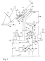
Von einem nicht weiter dargestellten Radlader ist ein Hubgerüst 1 schematisch dargestellt. Dieses Hubgerüst 1 ist an einem Anlenkpunkt 2 heb- und senkbar und an einem nicht weiter dargestellten Radladerrahmen gelagert. Am unteren Ende des Hubgerüstes 1 ist an einem Anlenkpunkt 3 eine Arbeitsausrüstung angelenkt, welche beim Ausführungsbeispiel in Form einer Schaufel 4 ausgebildet ist. Diese Schaufel 4 ist über einen Gelenkhebelmechanismus 5, 6 mittels eines allgemein mit 7 bezeichneten Kippzylinders gegenüber dem Hubgerüst 1 um den Anlenkpunkt 3 verschwenkbar.From a wheel loader, not shown, a
Der Kippzylinder 7 weist eine Kolbenstange 8 und einen Kolben 9 auf und ist an dem der Kolbenstange 8 gegenüberliegenden Ende in einem Anlenkpunkt 10 ebenfalls gelenkig am Rahmen des Radladers befestigt.The
Am außerhalb des Kippzylinders befindlichen Endbereich der Kolbenstange 8 ist eine Tragstange 11 befestigt, die an ihrem freien Ende eine als ein Teil einer Kippzylinderpositionsbestimmungseinrichtung bildenden Steuerfahne 12 trägt. Am Kippzylinder 7 selbst ist ein in diesem Beispiel als Näherungsschalter 13 ausgebildetes Bauteil als zweites Teil der Kippzylinderpositionsbestimmungseinrichtung angeordnet, das über eine elektrische Signalleitung 14 in Wirkverbindung mit einer elektronischen Steuerungseinrichtung 15 steht, deren Funktion nachfolgend näher erläutert wird. Die Kippzylinderpositionsbestimmungseinrichtung kann selbstverständlich auch auf andere Weise realisiert werden. Wesentlich ist, dass sie in der Lage ist, diejenige Position des Kippzylinders 8 zu erfassen, die der vorbestimmten in
Die Arbeitsmaschine, also in diesem Fall der Radlader, weist einen Antriebsmotor, beispielsweise einen Dieselmotor 17 auf, welcher drei Hydraulikaggregate antreibt, nämlich einen vorzugsweise verstellbaren hydrostatischen Fahrantrieb 18, eine Hydraulikpumpe 19 für die Arbeitshydraulik des Radladers und wenigstens eine weitere Hydraulikpumpe 20 für Nebenverbraucher. Dabei wird von den Hydraulikaggregaten 18, 19, 20 Hydrauliköl aus einem allgemein mit 21 bezeichneten Tank gefördert bzw. in diesen zurückgefördert.The working machine, in this case the wheel loader, has a drive motor, for example a
Die Hydraulikpumpe 19 für die Arbeitshydraulik dient unter anderem für eine normale Betätigung der Schaufel 4 durch den Fahrer über den Kippzylinder 7. Dazu ist die Pumpe 19 über eine Hydraulikleitung 22 mit einem Steuerschieber 23 verbunden, der mittels Steuerhebeln 24 direkt vom Fahrer betätigbar ist. Der Steuerschieber 23 ist über eine Hydraulikleitung 25 mit der Kolbenseite 26 und über eine Hydraulikleitung 27 mit dem Ringraum 28 des Kippzylinders 7 verbunden. Ferner ist eine Leitung 29 zum Tank 21 vorgesehen.The
Die Hydraulikpumpe 20 für die Nebenverbraucher dient z.B. zur Versorgung bzw. Antrieb eines Lüftermotors 30 eines Lüfters 31. Dabei ist die Hydraulikpumpe 20 über zwei Hydraulikleitungen 32 und 33 mit dem Lüftermotor 30 verbunden, wobei zwischen den beiden Hydraulikleitungen 32 und 33 ein elektromagnetisches 4/2-Wegeventil 34 angeordnet ist. In der in
Das Magnetventil 34 weist darüber hinaus zwei Anschlüsse 35, 36 auf, wobei an den Anschluss 35 eine Hydraulikleitung 37 angeschlossen ist, die mit dem Ringraum 28 des Kippzylinders 7 in Verbindung steht, wobei in dieser Leitung ein Rückschlagventil 38 angeordnet ist. An den Anschluss 36 ist eine Hydraulikleitung 39 angeschlossen, welche mit der Kolbenseite 26 des Kippzylinders 7 in Verbindung steht.The
Das elektromagnetische 4/2-Wegeventil 34 ist über eine elektrische Signalleitung 40 mit der Steuereinrichtung 15 verbunden, die wiederum ihrerseits mit einem als Schalter ausgebildeten Auslöseelement 41 verbunden ist.The electromagnetic 4/2-
Will der Fahrer die Rückführautomatik auslösen, betätigt er den Schalter bzw. das Auslöseelement 41, wodurch die Steuerungseinrichtung 15 das 4/2-Wegeventil 34 in die Schaltposition gemäß
Die Kolbenstange 8 des Kippzylinders 7 wird über die Hydraulikpumpe 20 solange ausgefahren und dadurch die Schaufel 4 entsprechend in Neutrallage geführt, bis von der Kippzylinderpositionsbestimmungseinrichtung 12, 13 festgestellt wird, dass die vorgegebene gewünschte maximale Ausfahrposition der Kolbenstange 8 und damit die gewünschte Neutrallage der Schaufel 4 erreicht ist. Über die Signalleitung 14 wird ein entsprechendes Signal an die Steuereinrichtung 15 abgegeben, welche das 4/2-Wegeventil 34 in die in
In den
Gemäß
In der in
Bei der Darstellung gemäß
In der in
Bei der in
Claims (5)
- Method for the positionally correct orientation of working equipment (4) arranged on a liftable and lowerable lifting frame (1) of a working machine in a tiltable manner, wherein the working equipment (4) is moved relative to the lifting frame (1) by means of a tilting cylinder (7), wherein the working equipment (4) is connected to the piston rod (8) of the tilting cylinder (7) by means of an articulated lever mechanism (5, 6), wherein the tilting cylinder (7) is supplied with hydraulic oil from a hydraulic pump (19) for the working hydraulic system by a direct-operated control valve (23), and wherein secondary consumers of the working machine are supplied with hydraulic oil from at least one other hydraulic pump (20),
wherein
following operation of a triggering element (41) by the driver, the two hydraulic connections (25, 27) of the tilting cylinder (7) designed as a differential cylinder are also connected to the hydraulic pump (20) for the secondary consumers by a switch-over valve (34) activated by a control device (15) thereby moving the tilting cylinder (7) in the direction of the neutral position of the working equipment (4), wherein the position of the tilting cylinder (7) is determined and monitored by the control device (15) of the switch-over valve (34), and wherein, on reaching the pre-set neutral position of the tilting cylinder (7), the control device (15) of the switch-over valve (34) switches the switch-over valve (34) into a position in which the two hydraulic connections (25, 27) of the tilting cylinder (7) are shut off from the hydraulic pump (20) for the secondary consumers. - Method according to claim 1,
characterised in that
a 4/2-way directional control valve is used as switch-over valve (34). - Working machine with a liftable and lowerable lifting frame (1) and working equipment (4) arranged in a tiltable manner relative to the lifting frame (1) by means of a tilting cylinder (7), wherein the working equipment (4) is connected to the piston rod (8) of the tilting cylinder (7) by means of an articulated lever mechanism (5, 6) and the tilting cylinder (7) is connected to a hydraulic pump (18) for the working hydraulic system by means of a direct-operated control valve (23), and wherein at least one further hydraulic pump (20) is provided, wherein the further hydraulic pump (20) is connected to the two hydraulic connections (25, 27) of the tilting cylinder (7) by means of a switch-over valve (34), wherein the switch-over valve (34) can be actuated by a triggering element (41) by means of a control device (15), wherein the tilting cylinder (7) is designed as a differential cylinder,
characterised in that
the further hydraulic pump (20) is provided for secondary consumers, and that the further hydraulic pump (20) is also connected to the two hydraulic connections (25, 27) of the tilting cylinder (7) by means of the switch-over valve (34),
wherein the tilting cylinder (7) is provided with a device for detecting (12, 13) the position of the tilting cylinder which is connected to the control device (15). - Working machine according to claim 3,
characterised in that
the switch-over valve (34) is configured as a 4/2-way directional control valve. - Working machine according to claim 3 or 4,
characterised in that
a non-return valve (38) is provided in the hydraulics line (37) between the switch-over valve (34) and the hydraulic connection (27) on the piston rod side (28) of the tilting cylinder (7).
Applications Claiming Priority (2)
| Application Number | Priority Date | Filing Date | Title |
|---|---|---|---|
| DE102006024731A DE102006024731B3 (en) | 2006-05-26 | 2006-05-26 | Method for aligning equipment tilting on a lifting and lowering structure of a machine e.g. wheel loader comprises connecting hydraulic connections of a tilting cylinder with a hydraulic pump and moving the cylinder into a neutral position |
| PCT/EP2007/003722 WO2007137662A1 (en) | 2006-05-26 | 2007-04-27 | Method for the positionally correct orientation of working equipment which is arranged in a tiltable manner on a lifting frame, which can be raised and lowered, of a working machine |
Publications (2)
| Publication Number | Publication Date |
|---|---|
| EP2029815A1 EP2029815A1 (en) | 2009-03-04 |
| EP2029815B1 true EP2029815B1 (en) | 2018-11-21 |
Family
ID=38261455
Family Applications (1)
| Application Number | Title | Priority Date | Filing Date |
|---|---|---|---|
| EP07724652.8A Active EP2029815B1 (en) | 2006-05-26 | 2007-04-27 | Method for the positionally correct orientation of working equipment which is arranged in a tiltable manner on a lifting frame, which can be raised and lowered, of a working machine |
Country Status (4)
| Country | Link |
|---|---|
| US (1) | US8146356B2 (en) |
| EP (1) | EP2029815B1 (en) |
| DE (1) | DE102006024731B3 (en) |
| WO (1) | WO2007137662A1 (en) |
Families Citing this family (4)
| Publication number | Priority date | Publication date | Assignee | Title |
|---|---|---|---|---|
| JP5027705B2 (en) * | 2008-03-25 | 2012-09-19 | 株式会社小松製作所 | Hydraulic oil supply device and construction machine |
| FR2938561A1 (en) * | 2008-11-20 | 2010-05-21 | Mailleux | AUTOMATIC LEVELING DEVICE FOR THE TOOL OF A HYDRAULIC CHARGER MOUNTED ON A TRACTOR |
| US10315853B2 (en) | 2015-08-10 | 2019-06-11 | Superior Industries, Inc. | Conveyor leveling systems and methods |
| CN106088187A (en) * | 2016-06-06 | 2016-11-09 | 郑州市小石头信息技术有限公司 | Forklift material loads intelligent identifying system |
Family Cites Families (8)
| Publication number | Priority date | Publication date | Assignee | Title |
|---|---|---|---|---|
| US3811587A (en) * | 1972-07-17 | 1974-05-21 | Case Co J I | Hydraulic leveling circuit for implement |
| JPH0791842B2 (en) | 1988-01-18 | 1995-10-09 | 株式会社小松製作所 | Bucket leveler equipment |
| JPH0639317B2 (en) * | 1989-09-09 | 1994-05-25 | 株式会社神戸製鋼所 | Displacement suppression mechanism for mobile cranes |
| DE4437300C2 (en) * | 1994-07-13 | 1996-12-05 | Orenstein & Koppel Ag | Method and device for positioning the work equipment tiltably arranged on a downwardly moving mast of a mobile working machine |
| EP0770163B1 (en) * | 1994-07-13 | 1999-05-26 | O & K Orenstein & Koppel Ag | Process for exactly positioning the tilting outfit mounted on the descending lift frame of movable construction machines |
| WO1996029478A1 (en) | 1995-03-22 | 1996-09-26 | Komatsu Ltd. | Bucket leveller device for an industrial vehicle |
| US6120237A (en) * | 1998-08-25 | 2000-09-19 | Rockland Inc. | Attachment for groundworking and material handling machines and a strut assembly therefor |
| DE20116947U1 (en) * | 2001-10-12 | 2002-04-04 | Weidemann Gmbh & Co Kg | Schnellauskippventil |
-
2006
- 2006-05-26 DE DE102006024731A patent/DE102006024731B3/en not_active Expired - Fee Related
-
2007
- 2007-04-27 US US12/302,261 patent/US8146356B2/en not_active Expired - Fee Related
- 2007-04-27 EP EP07724652.8A patent/EP2029815B1/en active Active
- 2007-04-27 WO PCT/EP2007/003722 patent/WO2007137662A1/en active Application Filing
Non-Patent Citations (1)
| Title |
|---|
| None * |
Also Published As
| Publication number | Publication date |
|---|---|
| DE102006024731B3 (en) | 2007-08-16 |
| US8146356B2 (en) | 2012-04-03 |
| US20090107133A1 (en) | 2009-04-30 |
| EP2029815A1 (en) | 2009-03-04 |
| WO2007137662A1 (en) | 2007-12-06 |
Similar Documents
| Publication | Publication Date | Title |
|---|---|---|
| EP1752587B1 (en) | Hydraulic arrangement | |
| EP2171285B1 (en) | Hydraulic control arrangement | |
| DE102004012382B4 (en) | Hydraulic arrangement | |
| EP1743981A1 (en) | Hydraulic arrangement | |
| DE202007005232U1 (en) | tipper | |
| DE19532769A1 (en) | Fluid pressure control system for hydraulic excavator with top rotating frame and jib | |
| EP1897847A2 (en) | Charging device | |
| DE112017003054T5 (en) | HYDRAULIC CONTROL SYSTEM | |
| EP1762535A2 (en) | Loader and method for loader | |
| DE10393484B4 (en) | Method and device for controlling a hydraulic pump for a working device of a working vehicle | |
| EP2029815B1 (en) | Method for the positionally correct orientation of working equipment which is arranged in a tiltable manner on a lifting frame, which can be raised and lowered, of a working machine | |
| DE2164628A1 (en) | OVERLOAD SHUT-OFF DEVICE FOR HYDRAULIC LIFTING AND LIFTING SYSTEMS ADJUSTMENT MECHANISMS, ESPECIALLY FOR HYDRAULIC LOADING CRANES | |
| DE2411051C2 (en) | Excavators, such as shovel excavators, shovel loaders or the like. | |
| DE2533673C2 (en) | Hydraulic control system | |
| EP1507087A2 (en) | Hydraulic control for a mobile working machine | |
| DE2517810A1 (en) | VEHICLE | |
| DE10063610B4 (en) | Control device for controlling a hydraulic rotary drive device | |
| EP3816095A1 (en) | Power machine with a frame and a pivotable boom | |
| EP1576241B1 (en) | Control device for a work device comprising a scoop held on an extension arm | |
| DE3508691C1 (en) | Hydraulic earthworks vehicle with a slewable boom | |
| DE102015118666A1 (en) | Hydraulic tilt drive of a load-handling device of a truck | |
| EP3564448B1 (en) | Utility vehicle with front loader | |
| DE19547696C1 (en) | Automatic flow rate changeover system e.g. for hydraulic excavator | |
| DE4437300C2 (en) | Method and device for positioning the work equipment tiltably arranged on a downwardly moving mast of a mobile working machine | |
| WO2022189197A1 (en) | Method and device for controlling a hydraulic lifting drive of a mobile work machine |
Legal Events
| Date | Code | Title | Description |
|---|---|---|---|
| PUAI | Public reference made under article 153(3) epc to a published international application that has entered the european phase |
Free format text: ORIGINAL CODE: 0009012 |
|
| 17P | Request for examination filed |
Effective date: 20081229 |
|
| AK | Designated contracting states |
Kind code of ref document: A1 Designated state(s): AT BE BG CH CY CZ DE DK EE ES FI FR GB GR HU IE IS IT LI LT LU LV MC MT NL PL PT RO SE SI SK TR |
|
| AX | Request for extension of the european patent |
Extension state: AL BA HR MK RS |
|
| DAX | Request for extension of the european patent (deleted) | ||
| RAP1 | Party data changed (applicant data changed or rights of an application transferred) |
Owner name: CNH INDUSTRIAL BAUMASCHINEN GMBH |
|
| 17Q | First examination report despatched |
Effective date: 20160108 |
|
| REG | Reference to a national code |
Ref country code: DE Ref legal event code: R079 Ref document number: 502007016504 Country of ref document: DE Free format text: PREVIOUS MAIN CLASS: E02F0003430000 Ipc: F15B0011024000 |
|
| GRAP | Despatch of communication of intention to grant a patent |
Free format text: ORIGINAL CODE: EPIDOSNIGR1 |
|
| RIC1 | Information provided on ipc code assigned before grant |
Ipc: E02F 3/43 20060101ALI20180626BHEP Ipc: E02F 9/22 20060101ALI20180626BHEP Ipc: F15B 11/024 20060101AFI20180626BHEP Ipc: F15B 15/28 20060101ALI20180626BHEP Ipc: F15B 11/17 20060101ALI20180626BHEP Ipc: E02F 9/20 20060101ALI20180626BHEP |
|
| STAA | Information on the status of an ep patent application or granted ep patent |
Free format text: STATUS: GRANT OF PATENT IS INTENDED |
|
| INTG | Intention to grant announced |
Effective date: 20180802 |
|
| GRAS | Grant fee paid |
Free format text: ORIGINAL CODE: EPIDOSNIGR3 |
|
| GRAA | (expected) grant |
Free format text: ORIGINAL CODE: 0009210 |
|
| STAA | Information on the status of an ep patent application or granted ep patent |
Free format text: STATUS: THE PATENT HAS BEEN GRANTED |
|
| AK | Designated contracting states |
Kind code of ref document: B1 Designated state(s): AT BE BG CH CY CZ DE DK EE ES FI FR GB GR HU IE IS IT LI LT LU LV MC MT NL PL PT RO SE SI SK TR |
|
| REG | Reference to a national code |
Ref country code: CH Ref legal event code: EP |
|
| REG | Reference to a national code |
Ref country code: IE Ref legal event code: FG4D Free format text: LANGUAGE OF EP DOCUMENT: GERMAN |
|
| REG | Reference to a national code |
Ref country code: DE Ref legal event code: R096 Ref document number: 502007016504 Country of ref document: DE |
|
| REG | Reference to a national code |
Ref country code: AT Ref legal event code: REF Ref document number: 1067881 Country of ref document: AT Kind code of ref document: T Effective date: 20181215 |
|
| REG | Reference to a national code |
Ref country code: NL Ref legal event code: MP Effective date: 20181121 |
|
| PG25 | Lapsed in a contracting state [announced via postgrant information from national office to epo] |
Ref country code: LT Free format text: LAPSE BECAUSE OF FAILURE TO SUBMIT A TRANSLATION OF THE DESCRIPTION OR TO PAY THE FEE WITHIN THE PRESCRIBED TIME-LIMIT Effective date: 20181121 Ref country code: BG Free format text: LAPSE BECAUSE OF FAILURE TO SUBMIT A TRANSLATION OF THE DESCRIPTION OR TO PAY THE FEE WITHIN THE PRESCRIBED TIME-LIMIT Effective date: 20190221 Ref country code: FI Free format text: LAPSE BECAUSE OF FAILURE TO SUBMIT A TRANSLATION OF THE DESCRIPTION OR TO PAY THE FEE WITHIN THE PRESCRIBED TIME-LIMIT Effective date: 20181121 Ref country code: LV Free format text: LAPSE BECAUSE OF FAILURE TO SUBMIT A TRANSLATION OF THE DESCRIPTION OR TO PAY THE FEE WITHIN THE PRESCRIBED TIME-LIMIT Effective date: 20181121 Ref country code: ES Free format text: LAPSE BECAUSE OF FAILURE TO SUBMIT A TRANSLATION OF THE DESCRIPTION OR TO PAY THE FEE WITHIN THE PRESCRIBED TIME-LIMIT Effective date: 20181121 Ref country code: IS Free format text: LAPSE BECAUSE OF FAILURE TO SUBMIT A TRANSLATION OF THE DESCRIPTION OR TO PAY THE FEE WITHIN THE PRESCRIBED TIME-LIMIT Effective date: 20190321 |
|
| PG25 | Lapsed in a contracting state [announced via postgrant information from national office to epo] |
Ref country code: PT Free format text: LAPSE BECAUSE OF FAILURE TO SUBMIT A TRANSLATION OF THE DESCRIPTION OR TO PAY THE FEE WITHIN THE PRESCRIBED TIME-LIMIT Effective date: 20190321 Ref country code: GR Free format text: LAPSE BECAUSE OF FAILURE TO SUBMIT A TRANSLATION OF THE DESCRIPTION OR TO PAY THE FEE WITHIN THE PRESCRIBED TIME-LIMIT Effective date: 20190222 Ref country code: NL Free format text: LAPSE BECAUSE OF FAILURE TO SUBMIT A TRANSLATION OF THE DESCRIPTION OR TO PAY THE FEE WITHIN THE PRESCRIBED TIME-LIMIT Effective date: 20181121 Ref country code: SE Free format text: LAPSE BECAUSE OF FAILURE TO SUBMIT A TRANSLATION OF THE DESCRIPTION OR TO PAY THE FEE WITHIN THE PRESCRIBED TIME-LIMIT Effective date: 20181121 |
|
| PG25 | Lapsed in a contracting state [announced via postgrant information from national office to epo] |
Ref country code: PL Free format text: LAPSE BECAUSE OF FAILURE TO SUBMIT A TRANSLATION OF THE DESCRIPTION OR TO PAY THE FEE WITHIN THE PRESCRIBED TIME-LIMIT Effective date: 20181121 Ref country code: DK Free format text: LAPSE BECAUSE OF FAILURE TO SUBMIT A TRANSLATION OF THE DESCRIPTION OR TO PAY THE FEE WITHIN THE PRESCRIBED TIME-LIMIT Effective date: 20181121 Ref country code: CZ Free format text: LAPSE BECAUSE OF FAILURE TO SUBMIT A TRANSLATION OF THE DESCRIPTION OR TO PAY THE FEE WITHIN THE PRESCRIBED TIME-LIMIT Effective date: 20181121 |
|
| REG | Reference to a national code |
Ref country code: DE Ref legal event code: R097 Ref document number: 502007016504 Country of ref document: DE |
|
| PG25 | Lapsed in a contracting state [announced via postgrant information from national office to epo] |
Ref country code: SK Free format text: LAPSE BECAUSE OF FAILURE TO SUBMIT A TRANSLATION OF THE DESCRIPTION OR TO PAY THE FEE WITHIN THE PRESCRIBED TIME-LIMIT Effective date: 20181121 Ref country code: EE Free format text: LAPSE BECAUSE OF FAILURE TO SUBMIT A TRANSLATION OF THE DESCRIPTION OR TO PAY THE FEE WITHIN THE PRESCRIBED TIME-LIMIT Effective date: 20181121 Ref country code: RO Free format text: LAPSE BECAUSE OF FAILURE TO SUBMIT A TRANSLATION OF THE DESCRIPTION OR TO PAY THE FEE WITHIN THE PRESCRIBED TIME-LIMIT Effective date: 20181121 |
|
| PLBE | No opposition filed within time limit |
Free format text: ORIGINAL CODE: 0009261 |
|
| STAA | Information on the status of an ep patent application or granted ep patent |
Free format text: STATUS: NO OPPOSITION FILED WITHIN TIME LIMIT |
|
| 26N | No opposition filed |
Effective date: 20190822 |
|
| PG25 | Lapsed in a contracting state [announced via postgrant information from national office to epo] |
Ref country code: SI Free format text: LAPSE BECAUSE OF FAILURE TO SUBMIT A TRANSLATION OF THE DESCRIPTION OR TO PAY THE FEE WITHIN THE PRESCRIBED TIME-LIMIT Effective date: 20181121 |
|
| REG | Reference to a national code |
Ref country code: CH Ref legal event code: PL |
|
| REG | Reference to a national code |
Ref country code: BE Ref legal event code: MM Effective date: 20190430 |
|
| PG25 | Lapsed in a contracting state [announced via postgrant information from national office to epo] |
Ref country code: MC Free format text: LAPSE BECAUSE OF FAILURE TO SUBMIT A TRANSLATION OF THE DESCRIPTION OR TO PAY THE FEE WITHIN THE PRESCRIBED TIME-LIMIT Effective date: 20181121 Ref country code: LU Free format text: LAPSE BECAUSE OF NON-PAYMENT OF DUE FEES Effective date: 20190427 |
|
| PG25 | Lapsed in a contracting state [announced via postgrant information from national office to epo] |
Ref country code: CH Free format text: LAPSE BECAUSE OF NON-PAYMENT OF DUE FEES Effective date: 20190430 Ref country code: LI Free format text: LAPSE BECAUSE OF NON-PAYMENT OF DUE FEES Effective date: 20190430 |
|
| PG25 | Lapsed in a contracting state [announced via postgrant information from national office to epo] |
Ref country code: BE Free format text: LAPSE BECAUSE OF NON-PAYMENT OF DUE FEES Effective date: 20190430 |
|
| PG25 | Lapsed in a contracting state [announced via postgrant information from national office to epo] |
Ref country code: TR Free format text: LAPSE BECAUSE OF FAILURE TO SUBMIT A TRANSLATION OF THE DESCRIPTION OR TO PAY THE FEE WITHIN THE PRESCRIBED TIME-LIMIT Effective date: 20181121 |
|
| PG25 | Lapsed in a contracting state [announced via postgrant information from national office to epo] |
Ref country code: IE Free format text: LAPSE BECAUSE OF NON-PAYMENT OF DUE FEES Effective date: 20190427 Ref country code: IT Free format text: LAPSE BECAUSE OF NON-PAYMENT OF DUE FEES Effective date: 20190427 |
|
| PGFP | Annual fee paid to national office [announced via postgrant information from national office to epo] |
Ref country code: FR Payment date: 20200420 Year of fee payment: 14 |
|
| REG | Reference to a national code |
Ref country code: AT Ref legal event code: MM01 Ref document number: 1067881 Country of ref document: AT Kind code of ref document: T Effective date: 20190427 |
|
| PGFP | Annual fee paid to national office [announced via postgrant information from national office to epo] |
Ref country code: GB Payment date: 20200424 Year of fee payment: 14 |
|
| PG25 | Lapsed in a contracting state [announced via postgrant information from national office to epo] |
Ref country code: AT Free format text: LAPSE BECAUSE OF NON-PAYMENT OF DUE FEES Effective date: 20190427 |
|
| REG | Reference to a national code |
Ref country code: DE Ref legal event code: R084 Ref document number: 502007016504 Country of ref document: DE |
|
| PG25 | Lapsed in a contracting state [announced via postgrant information from national office to epo] |
Ref country code: CY Free format text: LAPSE BECAUSE OF FAILURE TO SUBMIT A TRANSLATION OF THE DESCRIPTION OR TO PAY THE FEE WITHIN THE PRESCRIBED TIME-LIMIT Effective date: 20181121 |
|
| PG25 | Lapsed in a contracting state [announced via postgrant information from national office to epo] |
Ref country code: HU Free format text: LAPSE BECAUSE OF FAILURE TO SUBMIT A TRANSLATION OF THE DESCRIPTION OR TO PAY THE FEE WITHIN THE PRESCRIBED TIME-LIMIT; INVALID AB INITIO Effective date: 20070427 Ref country code: MT Free format text: LAPSE BECAUSE OF FAILURE TO SUBMIT A TRANSLATION OF THE DESCRIPTION OR TO PAY THE FEE WITHIN THE PRESCRIBED TIME-LIMIT Effective date: 20181121 |
|
| GBPC | Gb: european patent ceased through non-payment of renewal fee |
Effective date: 20210427 |
|
| PG25 | Lapsed in a contracting state [announced via postgrant information from national office to epo] |
Ref country code: FR Free format text: LAPSE BECAUSE OF NON-PAYMENT OF DUE FEES Effective date: 20210430 Ref country code: GB Free format text: LAPSE BECAUSE OF NON-PAYMENT OF DUE FEES Effective date: 20210427 |
|
| PGFP | Annual fee paid to national office [announced via postgrant information from national office to epo] |
Ref country code: DE Payment date: 20230426 Year of fee payment: 17 |