EP3771684B1 - Chariot de manutention doté d'un dispositif de levage - Google Patents
Chariot de manutention doté d'un dispositif de levage Download PDFInfo
- Publication number
- EP3771684B1 EP3771684B1 EP20184405.7A EP20184405A EP3771684B1 EP 3771684 B1 EP3771684 B1 EP 3771684B1 EP 20184405 A EP20184405 A EP 20184405A EP 3771684 B1 EP3771684 B1 EP 3771684B1
- Authority
- EP
- European Patent Office
- Prior art keywords
- lifting
- load
- mast
- control valve
- pressure accumulator
- Prior art date
- Legal status (The legal status is an assumption and is not a legal conclusion. Google has not performed a legal analysis and makes no representation as to the accuracy of the status listed.)
- Active
Links
- 230000000903 blocking effect Effects 0.000 claims description 3
- 239000000725 suspension Substances 0.000 description 14
- 230000004913 activation Effects 0.000 description 10
- 238000013016 damping Methods 0.000 description 9
- 230000007704 transition Effects 0.000 description 7
- 230000004044 response Effects 0.000 description 4
- 238000010586 diagram Methods 0.000 description 2
- 230000010355 oscillation Effects 0.000 description 2
- 230000036316 preload Effects 0.000 description 2
- 230000009172 bursting Effects 0.000 description 1
- 238000010276 construction Methods 0.000 description 1
- 230000008878 coupling Effects 0.000 description 1
- 238000010168 coupling process Methods 0.000 description 1
- 238000005859 coupling reaction Methods 0.000 description 1
- 230000009849 deactivation Effects 0.000 description 1
- 238000006073 displacement reaction Methods 0.000 description 1
- 230000002349 favourable effect Effects 0.000 description 1
- 239000012530 fluid Substances 0.000 description 1
- 239000010720 hydraulic oil Substances 0.000 description 1
- 238000009434 installation Methods 0.000 description 1
- 230000007935 neutral effect Effects 0.000 description 1
- 238000005457 optimization Methods 0.000 description 1
- 230000035939 shock Effects 0.000 description 1
Images

Classifications
-
- B—PERFORMING OPERATIONS; TRANSPORTING
- B66—HOISTING; LIFTING; HAULING
- B66F—HOISTING, LIFTING, HAULING OR PUSHING, NOT OTHERWISE PROVIDED FOR, e.g. DEVICES WHICH APPLY A LIFTING OR PUSHING FORCE DIRECTLY TO THE SURFACE OF A LOAD
- B66F9/00—Devices for lifting or lowering bulky or heavy goods for loading or unloading purposes
- B66F9/06—Devices for lifting or lowering bulky or heavy goods for loading or unloading purposes movable, with their loads, on wheels or the like, e.g. fork-lift trucks
- B66F9/075—Constructional features or details
- B66F9/20—Means for actuating or controlling masts, platforms, or forks
- B66F9/22—Hydraulic devices or systems
-
- B—PERFORMING OPERATIONS; TRANSPORTING
- B66—HOISTING; LIFTING; HAULING
- B66F—HOISTING, LIFTING, HAULING OR PUSHING, NOT OTHERWISE PROVIDED FOR, e.g. DEVICES WHICH APPLY A LIFTING OR PUSHING FORCE DIRECTLY TO THE SURFACE OF A LOAD
- B66F9/00—Devices for lifting or lowering bulky or heavy goods for loading or unloading purposes
- B66F9/06—Devices for lifting or lowering bulky or heavy goods for loading or unloading purposes movable, with their loads, on wheels or the like, e.g. fork-lift trucks
- B66F9/075—Constructional features or details
- B66F9/08—Masts; Guides; Chains
Definitions
- the invention relates to an industrial truck with a lifting device and with a hydraulic pressure accumulator device, the lifting device being provided for raising and lowering a load handling attachment, the lifting device having a hydraulic lifting cylinder device which has a pressure chamber which can be connected to the hydraulic pressure accumulator device, the lifting device is designed as a mast, which is designed as a multiple mast with a standing mast and at least one extension mast that can be raised and lowered relative to the standing mast, in which the load handling device can be raised and lowered, the mast having a free lift with a free lift area and a mast lift with a mast lift area, wherein the lifting cylinder device has at least one free lifting cylinder for raising and lowering the load handling device in the extension mast and has at least one lifting cylinder for raising and lowering the at least one extension mast in the fixed mast.
- industrial trucks have a load handling device which is fastened so that it can move in the vertical direction on a lifting device designed as a mast.
- loads for example loads arranged on pallets, can be lifted, transported and stacked with the load handling device, which is often designed as a load fork.
- a hydraulic lifting cylinder device for raising or lowering the load-carrying device, which can consist of one or more lifting cylinders that are connected directly or indirectly to the load-carrying device, often via a lifting chain or a lifting belt.
- the force required to lift the load is generated by the lifting cylinder device, which is connected to a control directional control valve via a hydraulic lifting line.
- This directional control valve usually has three switching positions, with the lifting line being able to be connected either to a hydraulic pump for raising the load-carrying device or to a container for lowering the load-carrying device or to be shut off to hold the load-carrying device. According to the respective switching position of the directional control valve, the load handling attachment is raised, lowered or held in the current position.
- the lifting cylinder device When the control directional valve is in the closed switching position, the lifting cylinder device represents an at least approximately rigid component, as a result of which the load handling device is not movably coupled to the frame of the industrial truck. As a result of this rigid coupling, vibrations and shocks, for example as a result of driving over bumps in the road, are transmitted immediately and directly from the load handling device with a load arranged thereon to the frame of the industrial truck.
- the load damping device essentially consists of a hydraulic pressure accumulator device which is connected to the pressure chamber of the lifting cylinder device.
- the hydraulic pressure accumulator device is connected to a lifting line leading to the lifting cylinder device.
- the hydraulic pressure accumulator device has the function of a spring. Due to the mass inertia of the load picked up, the impacts coming from the industrial truck and resulting from unevenness in the roadway are cushioned with the hydraulic pressure accumulator device and the load vibrates in relation to the industrial truck.
- the aperture assigned to the hydraulic pressure accumulator device also represents a strong damping of the suspension system formed by the hydraulic pressure accumulator device, so that the aperture acts contrary to the actual intended use of the hydraulic pressure accumulator device.
- the diameter of the aperture must therefore be selected depending on the lifting capacity of the industrial truck, the load weight of the load, the temperature of the hydraulic fluid and the size of the hydraulic pressure accumulator device used, and therefore requires many optimization loops and always forms a corresponding one Compromise.
- the DE 10 2014 113 208 A1 discloses an industrial truck with a duplex mast, in which the lifting cylinder device is assigned a pressure accumulator device designed as a gas pressure accumulator, which can be switched on and off by means of a control valve.
- the gas preload of the gas pressure accumulator is adjusted to the current loading condition by means of a gas preload changing device.
- the DE 10 2016 103 256 A1 discloses an industrial truck with a multiple mast.
- a proportional valve device is provided in addition to a control valve device controlling the lifting cylinder influences the flow conditions of the free lift cylinder and mast lift cylinder during the transition between free lift and mast lift.
- the EP 3 153 456 A1 discloses a telescopic handler in which the telescopic arm can be raised and lowered by means of a lifting cylinder and extended and retracted by means of an extension cylinder.
- a pressure accumulator device is assigned to the extension cylinder in order to avoid major damage to the telehandler in the event of a frontal collision, ie the telescopic arm hitting an obstacle.
- a safety device is assigned to the pressure accumulator device, which includes a sensor that detects the extension path of the extension cylinder and a control valve with which the pressure accumulator device can be switched on and off the extension cylinder.
- the safety device with the activation/deactivation of the pressure accumulator device depending on the extension path of the extension cylinder represents a safety function to prevent the pressure accumulator device from bursting when the extension cylinder is extended far enough in the event of a frontal collision due to the large amount of pressure medium flowing into the pressure accumulator device.
- the EP 1 659 087 A2 discloses a suspension system for a boom or a front loader arm of a telehandler, wheel loader or tractor.
- a pressure medium accumulator is connected to the displacement of a hydraulic cylinder and can be switched on and off by means of a valve.
- a sensor is provided on the lifting cylinder, which sensor detects the position of the hydraulic cylinder, for example a predetermined position of the hydraulic cylinder. The sensor activates the suspension function if the sensor detects the lowered position of the hydraulic cylinder. The suspension function itself is then activated with an additional activation switch.
- the WO 2013/155178 A1 discloses a telehandler with hydraulic suspension of the telescopic arm, with a pressure accumulator being able to be switched on and off the lifting cylinder of the telescopic arm by means of a valve. With a position sensor, the position of the telescopic arm is recorded.
- the telescopic arm occurs due to the loading of the pressure accumulator with pressure medium from the pressure chamber of the lifting cylinder, the movement of the telescopic arm is detected with the position sensor and the suspension is deactivated if, after activation of the suspension function, the movement of the telescopic arm exceeds a predetermined limit value.
- the object of the present invention is to provide an improved industrial truck of the type mentioned at the outset.
- a control valve is provided, the pressure accumulator device being able to be switched on and off by means of the control valve depending on the lifting height of the load-carrying means, the pressure accumulator device being switched on below a lifting height limit value of the load-carrying device by corresponding activation of the control valve and above the lifting height limit value of the load-carrying means, the pressure accumulator device is switched off by appropriate activation of the control valve, the lift height limit value being within the free lift range of the free lift.
- the hydraulic pressure accumulator device can be switched on and off in a simple manner with the control valve, so that there is no need for a constantly active orifice plate associated with the hydraulic pressure accumulator device, as is the case in the prior art with the disadvantages and compromises associated with the orifice plate.
- the pressure accumulator device below a lifting height limit value of the load handling device, the pressure accumulator device is activated by appropriate activation of the control valve, and above the lifting height limit value of the load handling device, the pressure accumulator device is deactivated by appropriate activation of the control valve. Since the incorrect response of the line rupture safety valve, particularly at the lift stage transitions takes place, by switching off the hydraulic pressure accumulator device above a specific lifting height limit value, an erroneous response of the line rupture protection valve can be avoided in a simple manner. Since the hydraulic pressure accumulator device is switched on below the lift height limit by means of the control valve, the spring and damping properties of the hydraulic pressure accumulator device can be fully utilized, i.e.
- the lifting device is designed as a lifting frame, which is designed as a multiple lifting frame with a standing mast and at least one extension mast that can be raised and lowered relative to the standing mast, in which the load handling device can be raised and lowered, the lifting frame having a free lift with a free lift area and a mast lift with a mast lifting area, wherein the lifting cylinder device has at least one free lifting cylinder for raising and lowering the load handling device in the extending mast and has at least one lifting cylinder for raising and lowering the at least one extending mast in the standing mast, the lifting height limit value being within the free lifting area of the free lift.
- Such a multiple lifting frame can be designed as a duplex mast or as a triplex mast, which is equipped with a free lift for the load handling device.
- Duplex masts have a stationary mast and an extension mast that can be raised and lowered on the stationary mast, the load handling device being arranged on the extension mast so that it can be raised and lowered.
- the lifting cylinder device has one or more lifting cylinders for raising and lowering the extension mast in the Fixed mast and at least one additional free lift cylinder for raising and lowering the load handling device on the extending mast.
- Triplex masts have a stationary mast, a first extension mast guided on the stationary mast and a second second extension mast guided on the first extension mast, with the load handling device being arranged such that it can be raised and lowered on the second extension mast.
- the lifting cylinder device has one or more lifting cylinders for raising and lowering the two extension masts and at least one additional free lift cylinder for raising and lowering the load handling device on the second extension mast.
- the line rupture safety valve responds incorrectly, particularly at the lift stage transitions between mast lift and free lift, the fact that the lift height limit value is within the free lift range of the free lift and thus the lift height limit value is smaller than the upper end of the free lift range can result in the hydraulic pressure accumulator device being switched off above the lift height limit value an erroneous response of the line rupture protection valve can be avoided in a simple manner. Since the hydraulic pressure accumulator device is switched on by means of the control valve below the lift height limit value, the spring and damping properties of the hydraulic pressure accumulator device can be fully utilized, i.e. without damping, during transport work of the industrial truck, in which the load handling device with a load picked up is lowered below the lift height limit value.
- the hydraulic pressure accumulator device is switched off by means of the control valve above the lifting height limit value. Storing and retrieving a load, in which the load handling attachment is raised above the lifting height limit, can therefore be carried out without disturbing after-oscillation and without the risk of a power failure safety valve responding and the associated risk of the truck tipping over and component failure.
- the control valve can be actuated electrically between a switched-on position and a switched-off position, and the control valve can be actuated with an electronic control device Connection, wherein the electronic control device is connected to a lifting height of the lifting device detecting the lifting height sensor device.
- the control valve can be controlled in a simple manner in such a way that the pressure accumulator device is switched on below the lifting height limit value and switched off above the lifting height limit value.
- the lift height sensor device can continuously detect the lift height of the load handling device.
- the lifting height limit value is then advantageously stored in the electronic control device, so that the control device can use the lifting height measured with the lifting height sensor to determine whether the load handling device is above or below the lifting height limit value.
- the lift height sensor device is designed as a lift height switch with which the lift height limit value can be detected.
- a lifting height switch which is attached to a mast of the industrial truck in such a way that it detects the lifting height limit value of the load handling device, it can be determined with little construction effort whether the load handling device is above or below the lifting height limit value.
- the switch-on position of the control valve is designed as a flow position and the switch-off position of the control valve is designed as a throttle position or blocking position. If the disconnected position is designed as a throttle position, the hydraulic pressure accumulator device is throttled in the disconnected position of the control valve.
- the pressure accumulator device is connected by means of a branch line to the pressure chamber of the lifting cylinder device or to a lifting line leading from a control directional valve controlling the lifting device to the lifting cylinder device.
- the invention enables a number of advantages:
- the fact that the hydraulic pressure accumulator device is switched off above the lifting height limit value means that the load-carrying means can be lifted above the lifting height limit value safely and sensitively to be worked.
- the hydraulic pressure accumulator device is switched on below the lift height limit value, the suspension behavior of the suspension system formed by the hydraulic pressure accumulator device can be fully utilized with the load suspension device lowered below the lift height limit value, since there is no throttled and/or damped behavior.
- service costs can be reduced, which arise due to a line rupture safety valve responding incorrectly.
- the time-consuming orifice adjustment of the orifice assigned to the hydraulic pressure accumulator device is no longer necessary.
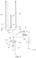
- an industrial truck 1 designed for example as a counterbalanced forklift truck, is shown as an example of an industrial truck.
- the industrial truck 1 is provided in the front area with a lifting device 2 designed as a mast for raising and lowering a load lifting device 3 carrying a load L.
- the industrial truck 1 is provided with a counterweight 4 in the rear area.
- the industrial truck 1 comprises a vehicle body 5 with a frame and a driver's canopy 6 which is arranged on the vehicle body 5 and within which a driver's workplace 7 is located.
- the driver's workplace 7 includes a driver's seat, not shown in detail, a steering device and at least one pedal arranged in a footwell for controlling a drive, not shown in detail.
- the working hydraulics can optionally a Tilting drive 10 of the mast and an additional consumer include, for example, a side shift drive for the load handling device 3.
- the truck 1 is supported by front wheels 11 and one or more rear wheels 12 on a roadway.
- the mast is designed as a multiple mast in the form of a duplex mast.
- the duplex mast comprises a stationary mast 2a, which is formed by two lateral vertical mast profiles arranged spaced apart in the transverse direction of the vehicle.
- the vertical mast 2a can be arranged on the industrial truck 1 so as to be adjustable in inclination by means of the tilting drive 10, which is formed by tilting cylinders.
- an extension mast (not shown in detail) is arranged such that it can be raised and lowered, on which the load handling device 3 is arranged such that it can be raised and lowered.
- the load handling device 3 is formed by a load fork with two forks 3a.
- the forks 3a are arranged on a fork carrier 3b, which is arranged on the extension mast so that it can be adjusted in height.
- the lifting device 2 For raising and lowering the lifting device 3, the lifting device 2 has a hydraulic lifting cylinder device 15 as a lifting drive figure 2 is shown in more detail.
- the industrial truck 1 has an unsprung chassis.
- the front wheels 11 and the rear wheels 12 are arranged without suspension on the vehicle body 5 and the counterweight 4, respectively.
- the lifting device 2 is also attached without suspension to the vehicle body 5 or to a drive axle carrying the front wheels 11 .
- FIG 2 a hydraulic circuit diagram of the lifting drive of the industrial truck 1 according to the invention is shown.
- a hydraulic pump 20 draws in pressure medium, for example hydraulic oil, from a container 21 and is connected via a delivery line 22 to a directional control valve 23, with which the lifting cylinder device 15 and thus the lifting and lowering movement of the load handling device 3 can be controlled.
- a lifting line 25 connects the directional control valve 23 to a pressure chamber 26 of the lifting cylinder device 15.
- the directional control valve 23, which preferably throttles in intermediate positions, has three switching positions. In a neutral position 23a, which the directional control valve 23, for example, as a result of spring force occupies the rest position, the delivery line 22 and the lifting line 25 are closed and the lifting line 25 is blocked.
- the control directional control valve 23 is in this switching position when no signal for raising or lowering the load L is specified by the operator.
- the control directional valve 23 is actuated into a lifting position 23b, in which the pump 20 is connected to the lifting line 25 of the lifting cylinder device 15, as a result of which piston rods of the lifting cylinder device 15 extend upwards as a result of the pressure present in a pressure chamber 26 of the lifting cylinder device 15.
- the control directional valve 23 is actuated into a lowering position 23c, in which the lifting line 25 of the lifting cylinder device 15 is connected to a tank line 27 which is connected to the control directional valve 23 and runs to the container 21, as a result of which the pressure chamber 26 of the lifting cylinder device 15 is connected to the Container 21 is connected and retract the piston rods of the lifting cylinder device 15 down.
- the lifting cylinder device 15 has two lifting cylinders 15a, 15b of a mast lift, which are used to raise and lower the or the extension masts of the multiple lifting frame.
- the lifting cylinder device 15 also has a free lifting cylinder 15c of a free lift, which is used to raise and lower the load handling device 3 on the extension mast.
- the lifting cylinders 15a, 15b, 15c are each designed as single-acting plunger cylinders, each having a piston rod extending in a cylinder housing and forming a corresponding pressure chamber 26 between the cylinder housing and the piston rod.
- the lifting cylinders 15a, 15b are fluidically connected in parallel in the illustrated embodiment.
- the free lift cylinder 15c is fluidically connected in series with the lift cylinder 15a in the exemplary embodiment shown. It goes without saying that, alternatively, the free lift cylinder 15c can be connected fluidically in parallel with the lift cylinders 15a, 15b.
- the free lifting cylinder 15c is connected to the fork carrier 3b via a lifting chain or a lifting belt.
- further lifting chains can be attached to the mast or lifting belts can be provided in order to couple the extension movement of several extension masts.
- a line rupture safety valve 16a, 16b, 16c is arranged at the lower ends of the lifting cylinders 15a, 15b, 15c.
- the pressure chambers 26 of the lifting cylinders 15a, 15b, 15c can be connected to a hydraulic pressure accumulator device 30 to reduce the vibrations and load impacts of the load L acting on the vehicle body 5 when driving over bumps in the roadway.
- the pressure accumulator device 30 is connected by means of a branch line 31 to the lifting line 25 leading from the control directional control valve 23 to the lifting cylinder device 15 .
- the pressure accumulator device 30 can be switched on and off by means of a control valve 35 depending on the lifting height of the load handling device 3 .
- the pressure accumulator device 30 is activated by appropriate activation of the control valve 35 and above the lifting height limit value HG of the load-carrying device 3 the pressure accumulator device 30 is deactivated by appropriate activation of the control valve 35.
- control valve 35 can be actuated electrically between a switch-on position 35a and a switch-off position 35b.
- the control valve 35 is connected to an electronic control device 36 which is connected to a lifting height sensor device 37 which detects the lifting height of the load-carrying means 3 .
- the switch-on position 35a of the control valve 35 is designed as a flow position.
- the switch-off position 35b of the control valve 35 is designed as a throttle position in the exemplary embodiment shown.
- the switched-off position 35b can be designed as a blocked position.
- control valve 35 is actuated by a spring 40 into the switched-on position 35a and can be actuated into the switched-off position 35b by means of an electrical actuating device 41, for example a switching magnet.
- the control valve 35 is thus designed as an electrically operated 2/2-way valve, for example a switching valve.
- the lifting height sensor device 37 is designed as a lifting height switch 38 with which the lifting height limit value HG of the load-receiving means 3 can be detected.
- the lifting height switch 38 is arranged, for example, on the vertical mast 2a of the mast and interacts with a counterpart 39 arranged on the load handling device 3, for example on the fork carriage 3b.
- the fork carriage 3b in the lowered extension mast can be raised to the upper end of the lowered extension mast for the free lift of the load handling device 3.
- the achievable with the free lift cylinder 15c free lift of the load handling device (forks 3a) is in figure 1 illustrated with a free lift area FH.
- the load-carrying means 3 can be raised together with the extension mast by means of the lifting cylinders 15a, 15b.
- the achievable with the lifting cylinders 15a, 15b Masthub is in the figure 1 illustrated with a mast lift range MH.
- the lift height limit HG is within the free lift range FH of the free lift.
- the lifting height switch 38 is arranged on the mast in such a way that it is actuated by the counterpart 39 on the load-carrying means 3 when the load-carrying means 3 is raised before the load-carrying means 3 reaches the upper end of the free lift range FH.
- the lifting height limit value HG is therefore smaller than the upper end of the free lift FH of the load handling device 3.
- the control valve 35 is actuated into the switch-on position 35a and the pressure accumulator device 30 is switched on and is therefore effective. If the load handling attachment 3 is above the lifting height limit value HG, the control valve 35 actuated in the disconnected position 35b and disconnected the pressure accumulator device 30 and thus not effective. Since the lift height limit value HG is less than the upper end of the free lift FH of the load handling attachment 3, the pressure accumulator device 30 is switched off during the transition from the free lift to the mast lift, so that an incorrect response and engagement of the power failure safety valves 16a, 16b, 16c can be effectively avoided.
- the hydraulic pressure accumulator device 30 Since the hydraulic pressure accumulator device 30 is switched on below the lift height limit value HG by means of the control valve 35 actuated in the switched-on position 35a, the spring and damping properties of the hydraulic pressure accumulator device 30 during transport work of the industrial truck 1 in which the load handling device 3 with the load L picked up is below the lift height limit value HG is lowered, can be fully utilized, i.e. without damping. Above the lifting height limit value, the hydraulic pressure accumulator device 30 is switched off by means of the control valve 35 actuated into the switched-off position 35b.
Landscapes
- Engineering & Computer Science (AREA)
- Transportation (AREA)
- Structural Engineering (AREA)
- Civil Engineering (AREA)
- Life Sciences & Earth Sciences (AREA)
- Geology (AREA)
- Mechanical Engineering (AREA)
- Chemical & Material Sciences (AREA)
- Combustion & Propulsion (AREA)
- Forklifts And Lifting Vehicles (AREA)
Claims (6)
- Chariot de manutention (1) avec un dispositif de levage (2) et avec un appareil d'accumulation de pression hydraulique (30), le dispositif de levage (2) étant prévu pour soulever et abaisser un moyen de réception de charge (3), le dispositif de levage (2) présentant un appareil de vérin de levage hydraulique (15) qui présente une chambre de pression (26) qui peut être reliée à l'appareil d'accumulation de pression hydraulique (30), le dispositif de levage (2) étant configuré sous forme de cadre de levage, qui est réalisé sous forme de cadre de levage multiple avec un mât fixe (2a) et au moins un mât déployable pouvant être soulevé et abaissé par rapport au mât fixe (2a), dans lequel le moyen de réception de charge (3) peut être soulevé et abaissé, le cadre de levage présentant une course libre avec une zone de course libre (FH) et une course de mât avec une zone de course de mât (MH), l'appareil de vérin de levage (15) présentant au moins un vérin de levage libre (15c) pour soulever et abaisser le moyen de réception de charge (3) dans le mât déployable et au moins un vérin de levage (15a, 15b) pour soulever et abaisser l'au moins un mât déployable dans le mât fixe (2a), caractérisé en ce qu'une soupape de commande (35) est prévue, l'appareil d'accumulation de pression (30) pouvant être activé et désactivé au moyen de la soupape de commande (35) en fonction de la hauteur de levage du moyen de réception de charge (3), en dessous d'une valeur limite de hauteur de levage (HG) du moyen de réception de charge (3), l'appareil d'accumulation de pression (30) étant activé par une commande correspondante de la soupape de commande (35) et, au-dessus de la valeur limite de hauteur de levage (HG) du moyen de réception de la charge (3), l'appareil d'accumulation de pression (30) étant désactivé par une commande correspondante de la soupape de commande (35), la valeur limite de hauteur de levage (HG) étant à l'intérieur de la zone de course libre (FH) de la course libre.
- Chariot de manutention selon la revendication 1, caractérisé en ce que la soupape de commande (35) peut être actionnée électriquement entre une position d'activation (35a) et une position de désactivation (35b) et la soupape de commande (35) est reliée à un appareil de commande électronique (36) pour la commande, l'appareil de commande électronique (36) étant relié à un appareil de détection de hauteur de levage (37) détectant la hauteur de levage du moyen de réception de charge (3).
- Chariot de manutention selon la revendication 2, caractérisé en ce que l'appareil de détection de hauteur de levage (37) détecte en continu la hauteur de levage du moyen de réception de charge (3) et la valeur limite de hauteur de levage (HG) est enregistrée dans l'appareil de commande électronique (36).
- Chariot de manutention selon la revendication 2, caractérisé en ce que l'appareil de détection de hauteur de levage (37) est configuré sous forme de commutateur de hauteur de levage (38), avec lequel la valeur limite de hauteur de levage (HG) peut être détectée.
- Chariot de manutention selon l'une quelconque des revendications 2 à 4, caractérisé en ce que la position d'activation (36a) de la soupape de commande (35) est configurée sous forme de position d'écoulement et la position de désactivation (35b) de la soupape de commande (35) est configurée sous forme de position d'étranglement ou position de blocage.
- Chariot de manutention selon l'une quelconque des revendications 1 à 5, caractérisé en ce que l'appareil d'accumulation de pression (30) est raccordé au moyen d'une conduite de dérivation (31) à la chambre de pression (26) de l'appareil de vérin de levage (15) ou à une conduite de levage (25) menant d'une soupape de commande (23) commandant le dispositif de levage (2) à l'appareil de vérin de levage (15).
Applications Claiming Priority (1)
| Application Number | Priority Date | Filing Date | Title |
|---|---|---|---|
| DE102019120504.2A DE102019120504A1 (de) | 2019-07-30 | 2019-07-30 | Flurförderzeug mit einer Hubvorrichtung |
Publications (2)
| Publication Number | Publication Date |
|---|---|
| EP3771684A1 EP3771684A1 (fr) | 2021-02-03 |
| EP3771684B1 true EP3771684B1 (fr) | 2023-06-07 |
Family
ID=71523021
Family Applications (1)
| Application Number | Title | Priority Date | Filing Date |
|---|---|---|---|
| EP20184405.7A Active EP3771684B1 (fr) | 2019-07-30 | 2020-07-07 | Chariot de manutention doté d'un dispositif de levage |
Country Status (2)
| Country | Link |
|---|---|
| EP (1) | EP3771684B1 (fr) |
| DE (1) | DE102019120504A1 (fr) |
Family Cites Families (6)
| Publication number | Priority date | Publication date | Assignee | Title |
|---|---|---|---|---|
| DE102004056418B4 (de) * | 2004-11-23 | 2013-02-28 | Deere & Company | Hydraulische Anordnung |
| ES2639340T3 (es) * | 2012-04-11 | 2017-10-26 | Clark Equipment Company | Sistema de suspensión del brazo de elevación para una máquina motorizada |
| DE102013114387A1 (de) * | 2013-12-18 | 2015-06-18 | Still Gmbh | Flurförderzeug mit einer Hubvorrichtung |
| DE102014113208A1 (de) * | 2014-09-12 | 2016-03-17 | Linde Material Handling Gmbh | Mobile Arbeitsmaschine, insbesondere Flurförderzeug |
| ITUB20154253A1 (it) * | 2015-10-09 | 2017-04-09 | Merlo Project Srl | Veicolo sollevatore con un braccio di sollevamento telescopico provvisto di un sistema ammortizzatore |
| DE102016103256A1 (de) * | 2015-12-29 | 2017-06-29 | Still Gmbh | Flurförderzeug mit einem Hubgerüst |
-
2019
- 2019-07-30 DE DE102019120504.2A patent/DE102019120504A1/de active Pending
-
2020
- 2020-07-07 EP EP20184405.7A patent/EP3771684B1/fr active Active
Also Published As
| Publication number | Publication date |
|---|---|
| EP3771684A1 (fr) | 2021-02-03 |
| DE102019120504A1 (de) | 2021-02-04 |
Similar Documents
| Publication | Publication Date | Title |
|---|---|---|
| DE60128599T2 (de) | Arbeitsgerät | |
| EP1574626B1 (fr) | Système hydraulique de suspension passive | |
| EP1762535B1 (fr) | Engin roulant du type muni d'un bras et procédé pour celui-ci | |
| EP1743981A1 (fr) | Agencement hydraulique | |
| DE102012101949A1 (de) | Hubvorrichtung eines Flurförderzeugs | |
| EP1764339B1 (fr) | Dispositif hydraulique pour un flèche de levage monté de manière pivotant sur un véhicule | |
| EP2805911B1 (fr) | Chariot de manutention, notamment chariot de préparation, avec poste de conduite relevable et abaissable | |
| EP3168187B1 (fr) | Dispositif de levage de chariot de manutention et methòde pour déposer la charge du moyen de réception de charges du chariot sur une surface de réception | |
| EP1897846B1 (fr) | Appareil de chargement | |
| EP3556722A1 (fr) | Chariot de manutention doté d'un dispositif de levage | |
| EP1507087A2 (fr) | Dispositif de commande hydraulique pour une machine de travail mobile | |
| EP1172277B1 (fr) | Chariot de manutention | |
| EP3771684B1 (fr) | Chariot de manutention doté d'un dispositif de levage | |
| EP3560885B1 (fr) | Chariot de manutention | |
| DE102014113208A1 (de) | Mobile Arbeitsmaschine, insbesondere Flurförderzeug | |
| EP2029815B1 (fr) | Procede d'alignement precis d'un equipement de travail monte de maniere a pouvoir basculer sur un chevalet de levage levable ou abaissable d'une machine de travail | |
| EP0931758B1 (fr) | Chariot élévateur avec un dispositif d'amortissement des chocs | |
| EP1908724B1 (fr) | Chariots de manutention dotés d'un essieu ajustable | |
| DE102013114387A1 (de) | Flurförderzeug mit einer Hubvorrichtung | |
| DE102018129688A1 (de) | Flurförderzeug | |
| EP2392540A1 (fr) | Chariot de manutention | |
| DE102015118666A1 (de) | Hydraulischer Neigeantrieb eines Lastaufnahmemittels eines Flurförderzeugs | |
| DE102018119222A1 (de) | Hubvorrichtung eines Flurförderzeugs und Verfahren zum Betrieb der Hubvorrichtung | |
| DE102014113209A1 (de) | Mobile Arbeitsmaschine, insbesondere Flurförderzeug | |
| DE102010022755A1 (de) | Flurförderzeug, insbesondere Gegengewichtsgabelstapler |
Legal Events
| Date | Code | Title | Description |
|---|---|---|---|
| PUAI | Public reference made under article 153(3) epc to a published international application that has entered the european phase |
Free format text: ORIGINAL CODE: 0009012 |
|
| STAA | Information on the status of an ep patent application or granted ep patent |
Free format text: STATUS: THE APPLICATION HAS BEEN PUBLISHED |
|
| AK | Designated contracting states |
Kind code of ref document: A1 Designated state(s): AL AT BE BG CH CY CZ DE DK EE ES FI FR GB GR HR HU IE IS IT LI LT LU LV MC MK MT NL NO PL PT RO RS SE SI SK SM TR |
|
| AX | Request for extension of the european patent |
Extension state: BA ME |
|
| STAA | Information on the status of an ep patent application or granted ep patent |
Free format text: STATUS: REQUEST FOR EXAMINATION WAS MADE |
|
| 17P | Request for examination filed |
Effective date: 20210720 |
|
| RBV | Designated contracting states (corrected) |
Designated state(s): AL AT BE BG CH CY CZ DE DK EE ES FI FR GB GR HR HU IE IS IT LI LT LU LV MC MK MT NL NO PL PT RO RS SE SI SK SM TR |
|
| GRAP | Despatch of communication of intention to grant a patent |
Free format text: ORIGINAL CODE: EPIDOSNIGR1 |
|
| STAA | Information on the status of an ep patent application or granted ep patent |
Free format text: STATUS: GRANT OF PATENT IS INTENDED |
|
| INTG | Intention to grant announced |
Effective date: 20230214 |
|
| GRAS | Grant fee paid |
Free format text: ORIGINAL CODE: EPIDOSNIGR3 |
|
| GRAA | (expected) grant |
Free format text: ORIGINAL CODE: 0009210 |
|
| STAA | Information on the status of an ep patent application or granted ep patent |
Free format text: STATUS: THE PATENT HAS BEEN GRANTED |
|
| AK | Designated contracting states |
Kind code of ref document: B1 Designated state(s): AL AT BE BG CH CY CZ DE DK EE ES FI FR GB GR HR HU IE IS IT LI LT LU LV MC MK MT NL NO PL PT RO RS SE SI SK SM TR |
|
| REG | Reference to a national code |
Ref country code: GB Ref legal event code: FG4D Free format text: NOT ENGLISH |
|
| P01 | Opt-out of the competence of the unified patent court (upc) registered |
Effective date: 20230507 |
|
| REG | Reference to a national code |
Ref country code: CH Ref legal event code: EP Ref country code: AT Ref legal event code: REF Ref document number: 1574537 Country of ref document: AT Kind code of ref document: T Effective date: 20230615 Ref country code: DE Ref legal event code: R096 Ref document number: 502020003507 Country of ref document: DE |
|
| REG | Reference to a national code |
Ref country code: LT Ref legal event code: MG9D |
|
| REG | Reference to a national code |
Ref country code: NL Ref legal event code: MP Effective date: 20230607 |
|
| PG25 | Lapsed in a contracting state [announced via postgrant information from national office to epo] |
Ref country code: SE Free format text: LAPSE BECAUSE OF FAILURE TO SUBMIT A TRANSLATION OF THE DESCRIPTION OR TO PAY THE FEE WITHIN THE PRESCRIBED TIME-LIMIT Effective date: 20230607 Ref country code: NO Free format text: LAPSE BECAUSE OF FAILURE TO SUBMIT A TRANSLATION OF THE DESCRIPTION OR TO PAY THE FEE WITHIN THE PRESCRIBED TIME-LIMIT Effective date: 20230907 Ref country code: ES Free format text: LAPSE BECAUSE OF FAILURE TO SUBMIT A TRANSLATION OF THE DESCRIPTION OR TO PAY THE FEE WITHIN THE PRESCRIBED TIME-LIMIT Effective date: 20230607 |
|
| PG25 | Lapsed in a contracting state [announced via postgrant information from national office to epo] |
Ref country code: RS Free format text: LAPSE BECAUSE OF FAILURE TO SUBMIT A TRANSLATION OF THE DESCRIPTION OR TO PAY THE FEE WITHIN THE PRESCRIBED TIME-LIMIT Effective date: 20230607 Ref country code: NL Free format text: LAPSE BECAUSE OF FAILURE TO SUBMIT A TRANSLATION OF THE DESCRIPTION OR TO PAY THE FEE WITHIN THE PRESCRIBED TIME-LIMIT Effective date: 20230607 Ref country code: LV Free format text: LAPSE BECAUSE OF FAILURE TO SUBMIT A TRANSLATION OF THE DESCRIPTION OR TO PAY THE FEE WITHIN THE PRESCRIBED TIME-LIMIT Effective date: 20230607 Ref country code: LT Free format text: LAPSE BECAUSE OF FAILURE TO SUBMIT A TRANSLATION OF THE DESCRIPTION OR TO PAY THE FEE WITHIN THE PRESCRIBED TIME-LIMIT Effective date: 20230607 Ref country code: HR Free format text: LAPSE BECAUSE OF FAILURE TO SUBMIT A TRANSLATION OF THE DESCRIPTION OR TO PAY THE FEE WITHIN THE PRESCRIBED TIME-LIMIT Effective date: 20230607 Ref country code: GR Free format text: LAPSE BECAUSE OF FAILURE TO SUBMIT A TRANSLATION OF THE DESCRIPTION OR TO PAY THE FEE WITHIN THE PRESCRIBED TIME-LIMIT Effective date: 20230908 |
|
| PGFP | Annual fee paid to national office [announced via postgrant information from national office to epo] |
Ref country code: FR Payment date: 20230731 Year of fee payment: 4 Ref country code: DE Payment date: 20230728 Year of fee payment: 4 |
|
| PG25 | Lapsed in a contracting state [announced via postgrant information from national office to epo] |
Ref country code: FI Free format text: LAPSE BECAUSE OF FAILURE TO SUBMIT A TRANSLATION OF THE DESCRIPTION OR TO PAY THE FEE WITHIN THE PRESCRIBED TIME-LIMIT Effective date: 20230607 |
|
| PG25 | Lapsed in a contracting state [announced via postgrant information from national office to epo] |
Ref country code: SK Free format text: LAPSE BECAUSE OF FAILURE TO SUBMIT A TRANSLATION OF THE DESCRIPTION OR TO PAY THE FEE WITHIN THE PRESCRIBED TIME-LIMIT Effective date: 20230607 |
|
| PG25 | Lapsed in a contracting state [announced via postgrant information from national office to epo] |
Ref country code: IS Free format text: LAPSE BECAUSE OF FAILURE TO SUBMIT A TRANSLATION OF THE DESCRIPTION OR TO PAY THE FEE WITHIN THE PRESCRIBED TIME-LIMIT Effective date: 20231007 |
|
| PG25 | Lapsed in a contracting state [announced via postgrant information from national office to epo] |
Ref country code: SM Free format text: LAPSE BECAUSE OF FAILURE TO SUBMIT A TRANSLATION OF THE DESCRIPTION OR TO PAY THE FEE WITHIN THE PRESCRIBED TIME-LIMIT Effective date: 20230607 Ref country code: SK Free format text: LAPSE BECAUSE OF FAILURE TO SUBMIT A TRANSLATION OF THE DESCRIPTION OR TO PAY THE FEE WITHIN THE PRESCRIBED TIME-LIMIT Effective date: 20230607 Ref country code: RO Free format text: LAPSE BECAUSE OF FAILURE TO SUBMIT A TRANSLATION OF THE DESCRIPTION OR TO PAY THE FEE WITHIN THE PRESCRIBED TIME-LIMIT Effective date: 20230607 Ref country code: PT Free format text: LAPSE BECAUSE OF FAILURE TO SUBMIT A TRANSLATION OF THE DESCRIPTION OR TO PAY THE FEE WITHIN THE PRESCRIBED TIME-LIMIT Effective date: 20231009 Ref country code: IS Free format text: LAPSE BECAUSE OF FAILURE TO SUBMIT A TRANSLATION OF THE DESCRIPTION OR TO PAY THE FEE WITHIN THE PRESCRIBED TIME-LIMIT Effective date: 20231007 Ref country code: EE Free format text: LAPSE BECAUSE OF FAILURE TO SUBMIT A TRANSLATION OF THE DESCRIPTION OR TO PAY THE FEE WITHIN THE PRESCRIBED TIME-LIMIT Effective date: 20230607 Ref country code: CZ Free format text: LAPSE BECAUSE OF FAILURE TO SUBMIT A TRANSLATION OF THE DESCRIPTION OR TO PAY THE FEE WITHIN THE PRESCRIBED TIME-LIMIT Effective date: 20230607 |
|
| PG25 | Lapsed in a contracting state [announced via postgrant information from national office to epo] |
Ref country code: PL Free format text: LAPSE BECAUSE OF FAILURE TO SUBMIT A TRANSLATION OF THE DESCRIPTION OR TO PAY THE FEE WITHIN THE PRESCRIBED TIME-LIMIT Effective date: 20230607 |
|
| REG | Reference to a national code |
Ref country code: CH Ref legal event code: PL |
|
| REG | Reference to a national code |
Ref country code: DE Ref legal event code: R097 Ref document number: 502020003507 Country of ref document: DE |
|
| PG25 | Lapsed in a contracting state [announced via postgrant information from national office to epo] |
Ref country code: MC Free format text: LAPSE BECAUSE OF FAILURE TO SUBMIT A TRANSLATION OF THE DESCRIPTION OR TO PAY THE FEE WITHIN THE PRESCRIBED TIME-LIMIT Effective date: 20230607 |
|
| REG | Reference to a national code |
Ref country code: BE Ref legal event code: MM Effective date: 20230731 |
|
| PG25 | Lapsed in a contracting state [announced via postgrant information from national office to epo] |
Ref country code: LU Free format text: LAPSE BECAUSE OF NON-PAYMENT OF DUE FEES Effective date: 20230707 |
|
| PG25 | Lapsed in a contracting state [announced via postgrant information from national office to epo] |
Ref country code: MC Free format text: LAPSE BECAUSE OF FAILURE TO SUBMIT A TRANSLATION OF THE DESCRIPTION OR TO PAY THE FEE WITHIN THE PRESCRIBED TIME-LIMIT Effective date: 20230607 Ref country code: LU Free format text: LAPSE BECAUSE OF NON-PAYMENT OF DUE FEES Effective date: 20230707 |
|
| PLBE | No opposition filed within time limit |
Free format text: ORIGINAL CODE: 0009261 |
|
| STAA | Information on the status of an ep patent application or granted ep patent |
Free format text: STATUS: NO OPPOSITION FILED WITHIN TIME LIMIT |
|
| REG | Reference to a national code |
Ref country code: IE Ref legal event code: MM4A |
|
| PG25 | Lapsed in a contracting state [announced via postgrant information from national office to epo] |
Ref country code: DK Free format text: LAPSE BECAUSE OF FAILURE TO SUBMIT A TRANSLATION OF THE DESCRIPTION OR TO PAY THE FEE WITHIN THE PRESCRIBED TIME-LIMIT Effective date: 20230607 Ref country code: CH Free format text: LAPSE BECAUSE OF NON-PAYMENT OF DUE FEES Effective date: 20230731 |
|
| PG25 | Lapsed in a contracting state [announced via postgrant information from national office to epo] |
Ref country code: SI Free format text: LAPSE BECAUSE OF FAILURE TO SUBMIT A TRANSLATION OF THE DESCRIPTION OR TO PAY THE FEE WITHIN THE PRESCRIBED TIME-LIMIT Effective date: 20230607 |
|
| 26N | No opposition filed |
Effective date: 20240308 |