EP3770547B1 - Steinanalysevorrichtung und verfahren zur bewertung von steinen - Google Patents
Steinanalysevorrichtung und verfahren zur bewertung von steinen Download PDFInfo
- Publication number
- EP3770547B1 EP3770547B1 EP19188508.6A EP19188508A EP3770547B1 EP 3770547 B1 EP3770547 B1 EP 3770547B1 EP 19188508 A EP19188508 A EP 19188508A EP 3770547 B1 EP3770547 B1 EP 3770547B1
- Authority
- EP
- European Patent Office
- Prior art keywords
- stone
- scanner
- analysis device
- conveying surface
- transverse direction
- Prior art date
- Legal status (The legal status is an assumption and is not a legal conclusion. Google has not performed a legal analysis and makes no representation as to the accuracy of the status listed.)
- Active
Links
Images

Classifications
-
- G—PHYSICS
- G01—MEASURING; TESTING
- G01B—MEASURING LENGTH, THICKNESS OR SIMILAR LINEAR DIMENSIONS; MEASURING ANGLES; MEASURING AREAS; MEASURING IRREGULARITIES OF SURFACES OR CONTOURS
- G01B11/00—Measuring arrangements characterised by the use of optical techniques
- G01B11/24—Measuring arrangements characterised by the use of optical techniques for measuring contours or curvatures
- G01B11/25—Measuring arrangements characterised by the use of optical techniques for measuring contours or curvatures by projecting a pattern, e.g. one or more lines, moiré fringes on the object
- G01B11/2518—Projection by scanning of the object
- G01B11/2522—Projection by scanning of the object the position of the object changing and being recorded
-
- G—PHYSICS
- G01—MEASURING; TESTING
- G01N—INVESTIGATING OR ANALYSING MATERIALS BY DETERMINING THEIR CHEMICAL OR PHYSICAL PROPERTIES
- G01N21/00—Investigating or analysing materials by the use of optical means, i.e. using sub-millimetre waves, infrared, visible or ultraviolet light
- G01N21/84—Systems specially adapted for particular applications
- G01N21/88—Investigating the presence of flaws or contamination
- G01N21/89—Investigating the presence of flaws or contamination in moving material, e.g. running paper or textiles
- G01N21/8901—Optical details; Scanning details
-
- B—PERFORMING OPERATIONS; TRANSPORTING
- B28—WORKING CEMENT, CLAY, OR STONE
- B28B—SHAPING CLAY OR OTHER CERAMIC COMPOSITIONS; SHAPING SLAG; SHAPING MIXTURES CONTAINING CEMENTITIOUS MATERIAL, e.g. PLASTER
- B28B17/00—Details of, or accessories for, apparatus for shaping the material; Auxiliary measures taken in connection with such shaping
- B28B17/0063—Control arrangements
- B28B17/0072—Product control or inspection
-
- G—PHYSICS
- G01—MEASURING; TESTING
- G01B—MEASURING LENGTH, THICKNESS OR SIMILAR LINEAR DIMENSIONS; MEASURING ANGLES; MEASURING AREAS; MEASURING IRREGULARITIES OF SURFACES OR CONTOURS
- G01B11/00—Measuring arrangements characterised by the use of optical techniques
- G01B11/02—Measuring arrangements characterised by the use of optical techniques for measuring length, width or thickness
- G01B11/06—Measuring arrangements characterised by the use of optical techniques for measuring length, width or thickness for measuring thickness ; e.g. of sheet material
- G01B11/0608—Height gauges
-
- G—PHYSICS
- G01—MEASURING; TESTING
- G01B—MEASURING LENGTH, THICKNESS OR SIMILAR LINEAR DIMENSIONS; MEASURING ANGLES; MEASURING AREAS; MEASURING IRREGULARITIES OF SURFACES OR CONTOURS
- G01B11/00—Measuring arrangements characterised by the use of optical techniques
- G01B11/02—Measuring arrangements characterised by the use of optical techniques for measuring length, width or thickness
- G01B11/06—Measuring arrangements characterised by the use of optical techniques for measuring length, width or thickness for measuring thickness ; e.g. of sheet material
- G01B11/0691—Measuring arrangements characterised by the use of optical techniques for measuring length, width or thickness for measuring thickness ; e.g. of sheet material of objects while moving
-
- G—PHYSICS
- G01—MEASURING; TESTING
- G01G—WEIGHING
- G01G11/00—Apparatus for weighing a continuous stream of material during flow; Conveyor belt weighers
-
- G—PHYSICS
- G01—MEASURING; TESTING
- G01N—INVESTIGATING OR ANALYSING MATERIALS BY DETERMINING THEIR CHEMICAL OR PHYSICAL PROPERTIES
- G01N21/00—Investigating or analysing materials by the use of optical means, i.e. using sub-millimetre waves, infrared, visible or ultraviolet light
- G01N21/84—Systems specially adapted for particular applications
- G01N21/88—Investigating the presence of flaws or contamination
- G01N21/8851—Scan or image signal processing specially adapted therefor, e.g. for scan signal adjustment, for detecting different kinds of defects, for compensating for structures, markings, edges
-
- G—PHYSICS
- G01—MEASURING; TESTING
- G01N—INVESTIGATING OR ANALYSING MATERIALS BY DETERMINING THEIR CHEMICAL OR PHYSICAL PROPERTIES
- G01N33/00—Investigating or analysing materials by specific methods not covered by groups G01N1/00 - G01N31/00
- G01N33/38—Concrete; Lime; Mortar; Gypsum; Bricks; Ceramics; Glass
- G01N33/383—Concrete or cement
-
- G—PHYSICS
- G01—MEASURING; TESTING
- G01N—INVESTIGATING OR ANALYSING MATERIALS BY DETERMINING THEIR CHEMICAL OR PHYSICAL PROPERTIES
- G01N21/00—Investigating or analysing materials by the use of optical means, i.e. using sub-millimetre waves, infrared, visible or ultraviolet light
- G01N21/84—Systems specially adapted for particular applications
- G01N2021/845—Objects on a conveyor
-
- G—PHYSICS
- G01—MEASURING; TESTING
- G01N—INVESTIGATING OR ANALYSING MATERIALS BY DETERMINING THEIR CHEMICAL OR PHYSICAL PROPERTIES
- G01N21/00—Investigating or analysing materials by the use of optical means, i.e. using sub-millimetre waves, infrared, visible or ultraviolet light
- G01N21/84—Systems specially adapted for particular applications
- G01N21/88—Investigating the presence of flaws or contamination
- G01N21/8851—Scan or image signal processing specially adapted therefor, e.g. for scan signal adjustment, for detecting different kinds of defects, for compensating for structures, markings, edges
- G01N2021/8887—Scan or image signal processing specially adapted therefor, e.g. for scan signal adjustment, for detecting different kinds of defects, for compensating for structures, markings, edges based on image processing techniques
Definitions
- the present invention relates to a stone analysis device for evaluating stones, which has at least two scanner units for scanning at least one physical property of the stones.
- the present invention also relates to a stone analysis method for evaluating stones and determining a distance of a conveying surface relative to the top surface of the stone on the conveying surface.
- the concrete blocks are usually produced on a production slab, or placed on such a slab after production. This production slab is then transported with the help of conveyor systems and, together with the blocks on it, is passed through a quality control system, which is usually located just behind the production line. This ensures direct feedback on the production quality.
- the physical properties of the stones are analyzed.
- the height profile of the production plate and of the concrete blocks on it is recorded using laser sensors.
- the concrete blocks are examined for unwanted elevations and depressions in the surface. These can occur during production if, for example, concrete that is too moist gets stuck on the mold stamps of the concrete block machine.
- the surface structure can be checked for irregularities that can arise, for example, from faulty concrete mixes. Edge chips can also be detected, which can occur, for example, when demoulding concrete blocks.
- the recorded quality data is evaluated and thus, for example, the height of the concrete blocks is determined.
- the height of the Seine has been measured with the help of laser distance sensors. These sensors measure the distance from the measurement object, i.e. the stones, and the production plate to the sensor with a laser beam and an integrated light sensor using the triangulation process. Usually only point lasers are used for this.
- the problem here is that either only one row of stones on the production plate can be measured per point laser, or the reflected beam, i.e. the beam to be measured, is covered if the measurement objects are too high and therefore cannot be detected or the distance to the production plate cannot be measured.
- This problem can also occur with line scanners.
- measuring the surface of the production panel is particularly difficult if the production panel is uneven or has damage in the form of cracks, for example. Such unevenness is difficult or impossible to detect, especially with point and line scanners, if the distance between the measuring objects is so small that the measuring laser beam does reach the surface of the production plate, but the reflected beam, which is to be detected, is covered by the measuring objects and therefore does not reach the detector.
- the object of the present invention is therefore to provide a stone analysis device that enables an exact height measurement of the stones with low technical and financial outlay at the same time.
- a stone analysis device for evaluating stones, in particular concrete stones is arranged on a conveyor device for conveying the stones with a conveying surface for placing the stones, which extends in a longitudinal direction and a transverse direction (which is preferably perpendicular to one another standing) extends.
- the stone analysis device also has at least a first scanner unit for scanning at least one physical property of the stones, an evaluation device for evaluating a signal output by the scanner unit, a control device and a display device.
- the scanner unit is spaced from the conveying surface in a vertical, longitudinal, and transverse direction.
- At least one second scanner unit is provided, which has at least one line scanner, with the height of at least one stone being able to be detected by both scanner units.
- at least two point scanners are provided. The combination of at least two point scanners and at least one line scanner makes it possible to capture a conveying surface of the production plate and thus to measure the exact height of all stones that are arranged in several rows on a production plate.
- the stone analysis device also has a frame on which the scanner units are arranged.
- This can be a completely closed frame, but it would also be possible for this frame to have one or more open areas.
- the first and preferably also the second scanner unit is arranged on a transverse profile of the frame that extends in the transverse direction, with the position of the first and/or second scanner unit preferably being changeable in the transverse and/or vertical direction.
- the position of the second scanner unit can preferably be changed in the transverse direction and/or vertical direction and/or longitudinal direction.
- the first scanner unit is preferably arranged on a carriage which is arranged displaceably on the cross profile. Particularly preferably, the carriage has at least one magnets on.
- the second scanner unit is arranged below a cover plate and/or on another carriage, which is arranged to be displaceable on the frame. Because the positions of the scanner units can be changed, they can be adjusted according to the requirements for different production batches.
- the line scanner is designed as a laser scanner and the point scanner is preferably designed as a laser scanner.
- the point scanner preferably works with a frequency between 1000 Hz and 15000 Hz, preferably between 2000 and 10000 Hz, particularly preferably between 2500 and 7500 Hz.
- the line of the line scanner is preferably generated by an optic that expands a laser beam.
- the line extends in the transverse direction over the conveying surface and in particular perpendicularly to the longitudinal direction mentioned above.
- the line scanner preferably works with a frequency between 1000 Hz and 50000 Hz, preferably between 2000 and 30000 Hz, particularly preferably between 2500 and 10000 Hz.
- a height profile image of the stones is preferably recorded by recording image lines which the line scanner records.
- Laser scanners have a particularly high level of precision, so that the stones can be precisely measured. In addition, the size of the laser beams can be adjusted very precisely.
- the first and/or second scanner unit has at least one light sensor.
- the emitted laser beam or the laser beam reflected by the stone or the conveying surface can be detected by a light sensor.
- the light sensor of the point scanner and/or line scanner is preferably designed as a CCD and/or CMOS sensor.
- the sensor of the line scanner preferably records between 1000 and 4000 points, preferably between 1000 and 2000 points, particularly preferably between 1200 and 1700 points.
- a resolution of approx. 1500 height values per image line can be achieved for the analysis of the stones.
- the line scanner is designed as a 3D line scan camera.
- the line scanner is able to measure a distance from a surface of at least one Steins and preferably able to measure a distance to another surface, for example the surface of the production plate, by a triangulation, transit time, and/or light section method.
- the point scanner is also able to measure a distance to a surface of at least one stone and, according to the invention, the point scanner is able to measure a distance to another surface, for example the surface of the production plate, using a triangulation, transit time, and /or to measure the light section method.
- a triangulation, transit time, and /or to measure the light section method As a result, an absolute distance between the production plate and at least one scanner unit and the absolute distance between the surface of at least one stone and at least one scanner unit can be recorded.
- the point scanner is preferably arranged rotated between 40° and 120°, more preferably between 60 and 100°, particularly preferably by 90° relative to the line scanner.
- the line scanner is aligned in the longitudinal direction and/or the point scanner is aligned in the transverse direction to a conveying direction.
- the stone analysis device has at least one detection device for detecting a conveying speed of the conveying surface.
- This is preferably a pulse generator, with which at least the second scanner unit can be controlled. It is conceivable that the pulse generator is designed as a coder.
- the encoder detects positions of a shaft and/or a drive unit and outputs a trigger signal, the positions being detectable optically, magnetically or mechanically.
- the pulse generator preferably triggers the line scanner and/or an image recording device on the basis of the trigger signal.
- any acceleration (or deceleration) can also be measured. This results in the advantage that the recording of image lines and/or brightness values and/or color values can be controlled depending on the conveying device.
- the surface of the stone can be analyzed by the second scanner unit.
- a brightness distribution of at least one surface of at least one stone facing the second scanner unit can preferably be determined by the second scanner unit.
- This brightness distribution can be evaluated by the evaluation unit and be converted to a gray value image. By analyzing this gray value image, it is possible to identify spots and/or undesired deformations of the surface of the stones and make them visible as defects using the display device and/or include them in an evaluation of production results.
- the stone analysis device has at least one position sensor, by means of which at least one position of the point scanner relative to the frame can be determined.
- the position sensor is preferably designed as a linear position sensor and/or as a measuring rod, with the position sensor detecting the position of at least one magnet of a carriage on which at least one point scanner is arranged.
- the positions of the point scanners and/or line scanners relative to the frame can also be determined in relation to one another. This means that the positions (or centers) of the individual stones and information about the gaps between the stones can be determined.
- the scanner units, the position sensor and the evaluation unit are preferably connected to one another in terms of data technology via cables or wirelessly, so that data can be exchanged. It is conceivable that the control device is also connected in terms of data to the scanner units, the position sensor and/or the evaluation unit. Based on this data, the relative height between a surface of the production slab, also between the stones, and the surface of all stones on the production slab can be determined. The positions of the individual stones recorded in this way can particularly preferably be stored in a database. This has the advantage that the actual height of the stones can be measured and defective stones can be sorted out after the analysis.
- the stone analysis device has at least one image recording device that is suitable and intended for spatially resolved recording of an image.
- the image recording device is preferably designed as a color camera or black-and-white camera and/or has a CCD sensor, a CMOS sensor and/or another sensor that can detect brightness values and/or color values. It is conceivable for the image recording device to be designed as a line camera and/or for individual image lines to be recorded, which can be combined to form an overall image.
- a color camera enables a color analysis of at least one surface of at least one stone facing the color camera. Color analysis is a check of compliance specified color tones for single-color surfaces of the stones and/or color distributions for multi-colored surfaces of the stones possible.
- the stone analysis device preferably has an illumination device.
- the lighting device preferably comprises LED lighting means, which enable a defined surface section of the conveying surface extending in the transverse direction and/or longitudinal direction to be illuminated in a manner that is constant and uniform in terms of time and color.
- a line that can be detected by the image recording device is preferably illuminated by the illumination device.
- the lighting device it is also conceivable for the lighting device to have other lighting means, for example a lighting means based on an incandescent wire and/or based on mercury vapor.
- the use of constant and even lighting enables color samples of different stone types to be captured under the same conditions. A deviation of the determined color samples from specified color samples can thus be optimally detected and evaluated.
- hairline cracks in stones can be detected through the use of high-resolution color cameras and special lighting.
- the stone analysis device has at least one reading unit that is suitable for reading a marking.
- a transponder signal or radio tag, a QR code and/or a barcode can be read by the reading unit. If the production plates have a corresponding code or radio tag, this radio tag and/or this code can be detected. This makes it possible to trace the production plates with the stones on them. In this way, defective stones can be sorted out by sorting robots after the analysis. It is also possible to measure and/or weigh the production slabs once before loading them with stones in order to be able to use the properties of the unloaded production slabs for later evaluations.
- the stone analysis device comprises at least one weight measuring unit, with which the weight of one and/or more stones on the conveying surface can be measured.
- the weight measuring unit is preferably designed as a load cell. The total weight of the production plate and/or the blocks located on it can be determined by the weight measuring unit. Deviations from specified weights can be identified in this way, so that incorrectly loaded production boards can be identified at an early stage and/or removed from the conveyor device.
- the standard version of the stone analysis device has at least two and preferably three point lasers and two line scanners.
- the frame is preferably made of aluminum, metal, plastic, wood and/or a composite material.
- the frame preferably has a frame made of aluminum profiles and/or strips.
- the stone analysis device has a control cabinet that includes the control device and/or evaluation device. In this way, the control device and/or evaluation device are arranged close to one another, so that their operation and/or maintenance is facilitated.
- the control device and evaluation device are preferably connected to one another in terms of data technology, via cable or radio.
- the analysis of the physical properties of the stones is automated and/or the control device controls the image recording device, the first scanner unit and/or the second scanner unit on the basis of a signal which the evaluation device emits.
- the control device particularly preferably also controls a sorting robot, which sorts out faulty blocks on the basis of the stored positions of the individual blocks.
- the object is also achieved by a stone analysis method for evaluating stones, in particular concrete blocks, according to claim 10.
- the stone analysis method is carried out by a stone analysis device for arrangement on a conveyor for conveying the stones and having a conveying surface for laying the stones which extends in a longitudinal direction and a transverse direction (which are preferably perpendicular to one another).
- the stone analysis device also has at least a first scanner unit for scanning at least one physical property of the stones, an evaluation device for evaluating a signal output by the scanner unit, a control device and a display device.
- the scanner unit is spaced from the conveying surface in a vertical, longitudinal, and transverse direction.
- the first scanner unit preferably transmits a first measurement signal to the evaluation unit.
- a second method step consists in detecting a second distance of a second scanner unit from an upper surface of a stone located on the conveying surface.
- the second scanner unit preferably transmits a second measurement signal to the evaluation unit.
- a third distance of the conveying surface is determined relative to the upper surface of the stone located on the conveying surface. In this way the exact height of a stone on the production plate can be measured.
- a position of the first scanner unit relative to the second scanner unit is determined and/or specified. This allows the positions of sensors for distance measurement to be recorded.
- the first scanner unit is designed as a point scanner, which detects the distance between the surfaces of stones and the point scanner and the distance from the surface of the production plate facing the scanner unit. In this way, gaps between stones and thus the surface of the production plate between stones can be detected, as well as the position of stones on the production plate. As a result, the number of bricks that are arranged in a row on the production plate with respect to the longitudinal direction can also be recorded.
- the second scanner unit is designed as a line scan camera, which uses the method of laser triangulation to record an absolute distance between the surface of the stones and the second scanner unit.
- a preferably linear position sensor determines the position of the first scanner unit relative to the frame and/or transmits a position signal the evaluation unit.
- the evaluation unit determines the positions of the blocks on the production slab, the gaps between the blocks and/or the relative distance between the surface of each block and the surface of the production slab. In this way, the individual height of each stone on the production plate can be measured.
- a measurement of the second scanner unit and/or an image recording device is controlled on the basis of the first measurement signal and/or a pulse signal which is emitted by a pulse generator.
- a color pattern and/or gray value pattern of the stones is determined via the image recording device, for example a color camera, and a color signal is sent to the evaluation unit.
- the stones are preferably evaluated automatically and/or manually on the basis of the color signal and predefined color limit values.
- the determined color pattern and/or gray value pattern is stored, preferably between 100 and 1000, more preferably between 150 and 800, particularly preferably between 250 and 500 color pattern and/or gray value pattern are stored.
- Stored color patterns and/or gray value patterns are preferably used as a basis for evaluations of determined color patterns and/or gray value patterns of the stones. This continuously trains the automatic evaluation.
- the above-mentioned device therefore preferably has a storage device for storing reference data and in particular image data.
- a height profile image of the production slab and the blocks located on it is generated during transport of the production slab on the basis of the first and/or second measurement signal.
- This height profile image is preferably sent as a signal to the display device and/or displayed as a 3D point cloud in the display device. This allows faulty stones to be made visible and evaluated.
- a weight of the production slab with blocks located on it and/or at least one block is determined using a weight measuring unit.
- the weight measuring unit preferably sends a weight signal to the evaluation unit.
- a block height is preferably additionally evaluated on the basis of stored parameters that contain specified information about a target height of the block and/or minimum and/or maximum tolerance and/or limit values.
- a stone surface is preferably additionally evaluated on the basis of stored parameters that contain specified information on tolerance values for a depth and area of a depression and/or height and area of an elevation.
- a stone color is preferably additionally evaluated on the basis of stored parameters that contain specified information on tolerance values for color deviations, areas of the same or similar colors and/or a relationship between individual colors of a stone.
- a weight is preferably additionally evaluated on the basis of stored parameters which contain specified information on tolerance values for the weight of the stones as a function of the determined stone height. Such an evaluation enables faulty stones to be identified and sorted out. It is conceivable that the weight of the stones is decisive for such an assessment.
- a weight of an empty production sheet is stored in the database linked to a marking of the same production sheet. This makes it possible to determine an empty weight of a production slab loaded with blocks and to subtract this empty weight from the weight of a production slab loaded with blocks and thus to determine a weight of the blocks.
- an average weight of several empty production panels is stored manually in the database via the control device.
- the stone analysis device 1 has a frame 5 and at least one first scanner unit 10 .
- the stone analysis device 1 has a modular structure, so that individual elements, in particular scanners and/or sensors, are arranged so that they can move relative to the frame 5 . It is also possible to add additional elements, in particular scanners and/or sensors, to the frame 5 subsequently, or to expand the frame with additional frame elements. In this way, the stone analysis device 1 can be arbitrarily adapted to the intended application.
- the conveyor device 3 has a base 6 and at least one chain conveyor, but preferably two chain conveyors 3a, which can be moved in the longitudinal direction L, so that a conveyor element 4a with a conveyor surface 4 can be transported in the longitudinal direction L by the chain conveyors 3a via the conveyor device.
- a pulse generator 50 and/or a weight measuring unit 70 of the stone analysis device 1 are also arranged on the conveyor device 3 .
- the conveyor device is designed as a conveyor belt or slideway, or has V-belts for conveying panels.
- the chain tracks 3a extend in the longitudinal direction L from a rear end 3b to a front end 3c of the conveyor 3 side surface 3f extending in the vertical direction V and the transverse direction Q.
- At least two gear wheels are arranged at one end 3b, 3c of the conveyor device 3 and are connected to one another by a rotatable axis 3e.
- At least one pulse generator 50 is arranged on a gear wheel and/or the rotatable axis.
- the conveyor device 3 contacts the base 6 through support elements 7.
- At least one weight measuring unit 70 is preferably arranged between the base 6 and the support elements 7, between the support elements 7 and the conveyor device 3 and/or between the conveyor device 3 and the conveyor element 4a.
- the frame 5 has vertical elements 5V, longitudinal elements 5L, transverse elements 5Q and/or a cover plate 8 which extends in a longitudinal direction L and a transverse direction Q.
- Lateral covers (not shown), which extend in the longitudinal L and vertical direction V, are preferably also arranged on the vertical elements 5V.
- a front vertical element 5Va and a rear vertical element 5Vb are arranged at ends of a longitudinal element 5L and two longitudinal elements 5L are arranged at ends of one of two transverse elements 5Q.
- the cover plate is arranged on at least two longitudinal elements 5L and at least one transverse element 5Q.
- the conveyor device 3 is arranged between the two front vertical elements 5Va and the two rear vertical elements 5Vb, with the front vertical elements 5Va and rear vertical elements 5Vb being spaced apart from one another in such a way that the conveyor device 3 causes a conveyor element 4a with a preferred width with respect to the transverse direction Q between 100 cm and 300 cm, more preferably between 120 cm and 150 cm.
- Two height adjustment devices 41 are arranged on the two front vertical elements 5Va, which are opposite one another, the height adjustment devices 41 being arranged in the vertical direction V above the conveyor device 3 and above the conveyor surface 4 .
- the lighting device 45 extends between the two height adjustment devices 41 and its height with respect to the vertical direction V can be changed by the height adjustment devices 41 .
- At least two holding elements 42 are arranged on the lighting device 45 and/or one height adjustment device 41 each, at the upper ends 43 of which the image recording device 40 is brought.
- the height of the image recording device 40 relative to the vertical direction V can be changed by the height adjustment devices 41 depending on or independently of the lighting device 45 .
- the lighting device 45 has two lighting elements 45a, which extend in the transverse direction and are spaced apart from one another with respect to the longitudinal direction L. Furthermore, the lighting elements 45a are aligned parallel to the conveying surface 4, with the image recording device 40 being aligned in such a way that it captures an image of a section of the conveying surface 4 between the two lighting elements 45a.
- a transverse profile 9 is arranged between the two rear vertical elements 5Vb, which extends in the transverse direction Q and has at least one groove running in the transverse direction Q.
- At least one carriage 11, which can be displaced in the transverse direction, is arranged on the groove 9a.
- the carriage 11 has at least a first scanner unit 10 and a magnet.
- a position sensor which is preferably in the form of a strip, is arranged parallel to the transverse transverse profile.
- the position sensor 30 also extends in the transverse direction Q and is placed between the two rear vertical elements 5Vb and/or above the transverse profile 9 and/or above the first scanner unit 10 .
- the position sensor 30 is able to detect the magnet of the carriage 11 and in this way to record the position of the first scanner unit 10 relative to the frame 5 .
- the stone analysis device 1 has three first scanner units 10 which are designed as point scanners 10 .
- the three point scanners 10 are preferably each arranged on a carriage, each with a magnet.
- One point scanner 10 is aligned in such a way that a point scanner 10 is arranged above a respective chain track 3a with respect to the vertical direction V and transverse direction Q and a laser beam 10a strikes the conveying surface 4 perpendicularly with respect to the longitudinal direction L and transverse direction Q.
- the third point scanner 10 is aligned in such a way that the laser beam 10a strikes the conveying surface 4 perpendicularly with respect to the longitudinal direction L and the transverse direction Q, preferably at a center line M.
- the point scanners are preferably arranged between 10 cm and 150 cm, more preferably between 30 cm and 100 cm, particularly preferably between 50 cm and 80 cm, with respect to the vertical direction V above the conveying surface 4 .
- the stone analysis device 1 preferably has two second scanner units 20 which are designed as line scanners 20, preferably as laser line scanners.
- the laser beam 20b emitted by the line scanner extends in relation to the transverse direction Q and/or spreads out in a fan-like manner and impinges on the conveying surface 4 and/or the surface 2b of the stones 2 up.
- the scan line 20a is oriented parallel to the transverse direction Q and perpendicular to the longitudinal direction L and vertical direction V .
- the line scanners 20 are preferably arranged between 20 cm and 200 cm, more preferably between 50 cm and 150 cm, particularly preferably between 65 cm and 100 cm, with respect to the vertical direction V above the conveying surface 4 .
- the line scanners 20 are arranged on and/or at least one transverse element 5Q.
- a switch cabinet 86 is arranged on a vertical element 5V, transverse element 5Q and/or longitudinal element.
- the switch cabinet 86 has an evaluation device 80 and/or a control device 85 .
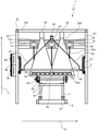
- the stone analysis device 1 is shown in a front view.
- the three point scanners 10 are arranged on the movable carriage 11 with the magnets 11a on the groove 9a of the transverse profile 9.
- the point scanners 10 are arranged next to one another and at a distance from one another with respect to the transverse direction Q.
- the position sensor 30 is arranged parallel to the cross section 9 .
- the line scanners 20 are arranged at a greater distance from the conveying surface 4 than the point scanners 10.
- the conveying surface with the stones 2 located thereon is below the point scanner 10, the line scanner 20, the lighting device 45 and/or the image recording device 40 is arranged.
- the height of the stones 2a can be optimally measured by the point scanner 10 and/or the line scanner 20.
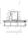
- the stone analysis device 1 is shown in a side view.
- the conveying element 4a with the stones 2 located on it is conveyed in the conveying direction FR via the conveying device 3 and the chain conveyors.
- the measuring devices are arranged one behind the other with respect to the longitudinal direction L, so that the pulse generator 50 is arranged at the rear end 3b of the conveyor device 3 .
- the illuminating device 45 and the image pickup device 40 are arranged closer to the rear end 3b than to the front end 3c.
- the point scanners 10 are arranged closer to the front end 3c than to the rear end 3b.
- the line scanners 20 are arranged between the point scanners 10 and the image recording device 40 .
- a reading unit is arranged below the conveying element 4a with respect to the vertical direction V, on the conveying device 3 and/or with respect to the longitudinal direction L between the rear end 3b and the lighting device 45, or between the lighting device 45 and the line scanner 20 and/or the point scanner 10.
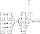
- a stone analysis method 100 for evaluating 210 stones 2 is shown.
- a first distance 110 of the first scanner unit 10 from the conveying surface 4 is recorded.
- the first scanner unit 10 preferably transmits a first measurement signal 111 to the evaluation unit 80 on the basis of the first distance 110.
- a second method step consists in detecting a second distance 120 of a second scanner unit 20 from an upper surface 2b of a stone 2 located on the conveying surface 4 .
- the second scanner unit 20 preferably transmits a second measurement signal 122 to the evaluation unit 80 on the basis of the second distance 120.
- An advantageous method step provides for the position sensor 30 to detect a position 140 of a magnet of a carriage on which the first scanner unit is arranged, ie a position 140 of the first scanner unit 10 relative to the frame 5 .
- Position sensor 30 preferably transmits a position signal 144 to evaluation unit 80 based on position 140.
- An advantageous method step provides that a color pattern 150 of the stones is determined via the image recording device 40 and on the basis of this a color signal 155 is sent to the evaluation unit 80 .
- a weight 160 of the conveying element 4a with the stones 2 located thereon is preferably also determined and, on the basis thereof, a weight signal 166 is sent from the weight measuring unit 70 to the evaluation unit 80 .
- first measurement signal 111, second measurement signal 122, position signal 144, color signal 155 and/or weight signal 166 are evaluated in evaluation unit 80.
- a stone height 2a or a third distance 130 of the conveying surface 4 becomes relative to the upper surface 2b of the stone 2 located on the conveying surface 4, a height profile image 131, a stone surface 170, a stone color 180 and/or a stone weight 130 is determined.
- stored parameters 200 are used to evaluate 210 the bricks 2 .
- the stored parameters 200 preferably have default values which, together with the stone height 2a, the height profile image 131, the stone surface 170, the stone color 180 and/or the stone weight 130, form a basis for the assessment 210.
- the default values or stored parameters 200 preferably have information on tolerance values for a depth and area of a depression and/or height and area of an elevation of a stone surface, as well as information on tolerance values for color deviations, areas of the same or similar colors and/or a ratio of individual colors of a stone to each other, as well as information on tolerance values for a stone weight 190 depending on the determined stone height 2a.
Landscapes
- General Physics & Mathematics (AREA)
- Physics & Mathematics (AREA)
- Engineering & Computer Science (AREA)
- Chemical & Material Sciences (AREA)
- Life Sciences & Earth Sciences (AREA)
- Health & Medical Sciences (AREA)
- Immunology (AREA)
- Pathology (AREA)
- Biochemistry (AREA)
- General Health & Medical Sciences (AREA)
- Analytical Chemistry (AREA)
- Ceramic Engineering (AREA)
- Computer Vision & Pattern Recognition (AREA)
- Food Science & Technology (AREA)
- Medicinal Chemistry (AREA)
- Signal Processing (AREA)
- Textile Engineering (AREA)
- Mechanical Engineering (AREA)
- Length Measuring Devices By Optical Means (AREA)
- Investigating Materials By The Use Of Optical Means Adapted For Particular Applications (AREA)
Priority Applications (4)
| Application Number | Priority Date | Filing Date | Title |
|---|---|---|---|
| PL19188508.6T PL3770547T3 (pl) | 2019-07-26 | 2019-07-26 | Urządzenie do analizy bloków i sposób oceny bloków |
| EP19188508.6A EP3770547B1 (de) | 2019-07-26 | 2019-07-26 | Steinanalysevorrichtung und verfahren zur bewertung von steinen |
| CA3087545A CA3087545C (en) | 2019-07-26 | 2020-07-15 | Stone-block analysis device and methods for the evaluation of stone blocks |
| US16/939,835 US11243173B2 (en) | 2019-07-26 | 2020-07-27 | Stone-block analysis device and methods for the evaluation of stone blocks |
Applications Claiming Priority (1)
| Application Number | Priority Date | Filing Date | Title |
|---|---|---|---|
| EP19188508.6A EP3770547B1 (de) | 2019-07-26 | 2019-07-26 | Steinanalysevorrichtung und verfahren zur bewertung von steinen |
Publications (2)
| Publication Number | Publication Date |
|---|---|
| EP3770547A1 EP3770547A1 (de) | 2021-01-27 |
| EP3770547B1 true EP3770547B1 (de) | 2022-02-23 |
Family
ID=67439023
Family Applications (1)
| Application Number | Title | Priority Date | Filing Date |
|---|---|---|---|
| EP19188508.6A Active EP3770547B1 (de) | 2019-07-26 | 2019-07-26 | Steinanalysevorrichtung und verfahren zur bewertung von steinen |
Country Status (4)
| Country | Link |
|---|---|
| US (1) | US11243173B2 (pl) |
| EP (1) | EP3770547B1 (pl) |
| CA (1) | CA3087545C (pl) |
| PL (1) | PL3770547T3 (pl) |
Cited By (1)
| Publication number | Priority date | Publication date | Assignee | Title |
|---|---|---|---|---|
| EP4467924A1 (de) | 2023-05-25 | 2024-11-27 | Ibea Ingenieurbüro für Elektronik und Automatisation GmbH | Inspektionsvorrichtung für baustoffe und verfahren zur inspektion von baustoffen |
Families Citing this family (11)
| Publication number | Priority date | Publication date | Assignee | Title |
|---|---|---|---|---|
| NL2025856B1 (en) * | 2020-06-18 | 2022-02-17 | Singa Ip B V | Device and method for determining the three-dimensional geometry of an individual object |
| DE102021114200B3 (de) | 2021-06-01 | 2022-11-10 | Deutsches Zentrum für Luft- und Raumfahrt e.V. | Verfahren und Vorrichtung zum Bestimmen der Sensorgüte eines Laserlichtschnittsensors |
| CN113442310B (zh) * | 2021-06-01 | 2023-07-28 | 巢湖市永安新型建材有限责任公司 | 一种加气块生产用自动化开槽装置 |
| DE102022000006A1 (de) | 2021-09-23 | 2023-03-23 | Adnan Atilgan | Vorrichtung zur Oberflächenbearbeitung von Werkstücken und Verfahren zur Verwendung der Vorrichtung |
| CN113933088B (zh) * | 2021-10-08 | 2023-04-25 | 淮北矿业股份有限公司淮北选煤厂 | 一种煤炭样品的智能采样与预处理系统 |
| CN113639803B (zh) * | 2021-10-15 | 2021-12-28 | 山东省地质矿产勘查开发局第四地质大队(山东省第四地质矿产勘查院) | 一种用于古化石认定及分析测量的一体化设备 |
| CN114670326B (zh) * | 2022-04-29 | 2024-05-07 | 山东铁信建设集团有限公司 | 一种变形矫正的装配式建筑零件用检测装置及检测方法 |
| CN116690820A (zh) * | 2022-11-02 | 2023-09-05 | 广东博智林机器人有限公司 | 基于切割控制参数的智能切割机自动切割方法及装置 |
| DE102024103011A1 (de) * | 2024-02-02 | 2024-12-19 | Hess Group Gmbh | Vorrichtung zur Oberflächenanalyse von Steinen und System zum Herstellen von Steinen |
| EP4603248A1 (de) * | 2024-02-15 | 2025-08-20 | OMAG Maschinenbau GmbH | Verfahren zur erfassung einer produkteinheit und produkterfassungseinrichtung |
| CN118811434B (zh) * | 2024-07-22 | 2025-04-04 | 深圳市森棋印刷有限公司 | 一种包装盒码垛装置及方法 |
Family Cites Families (6)
| Publication number | Priority date | Publication date | Assignee | Title |
|---|---|---|---|---|
| JPH0765957B2 (ja) * | 1989-04-27 | 1995-07-19 | アイエルビー株式会社 | コンクリート製品の不良品検出装置 |
| JPH07128029A (ja) * | 1993-11-02 | 1995-05-19 | Nittetsu Hokkaido Seigyo Syst Kk | 連続成形セメント製品の形状計測装置 |
| DE4341894C1 (de) * | 1993-12-08 | 1995-07-06 | Betonwerk Lintel Gmbh & Co Kg | Verfahren zur Qualitätssicherung bzw. zur Qualitätsüberwachung von aus Beton hergestellten Produkten |
| DE29702402U1 (de) * | 1997-02-12 | 1997-04-10 | ELSAT Elektroanlagen GmbH, 26683 Saterland | Einrichtung zur Qualitätsprüfung von Formkörpern, insbesondere Betonsteinen |
| CA2836797C (en) * | 2011-06-06 | 2018-05-15 | Troxler Electronic Laboratories, Inc. | Optical method and apparatus for determining a characteristic such as volume and density of an excavated void in a construction material |
| JP6681743B2 (ja) * | 2016-02-26 | 2020-04-15 | 株式会社キーエンス | 画像検査装置、画像検査方法、画像検査プログラム及びコンピュータで読み取り可能な記録媒体並びに記録した機器 |
-
2019
- 2019-07-26 PL PL19188508.6T patent/PL3770547T3/pl unknown
- 2019-07-26 EP EP19188508.6A patent/EP3770547B1/de active Active
-
2020
- 2020-07-15 CA CA3087545A patent/CA3087545C/en active Active
- 2020-07-27 US US16/939,835 patent/US11243173B2/en active Active
Cited By (2)
| Publication number | Priority date | Publication date | Assignee | Title |
|---|---|---|---|---|
| EP4467924A1 (de) | 2023-05-25 | 2024-11-27 | Ibea Ingenieurbüro für Elektronik und Automatisation GmbH | Inspektionsvorrichtung für baustoffe und verfahren zur inspektion von baustoffen |
| DE102023113821A1 (de) | 2023-05-25 | 2024-11-28 | ibea Ingenieurbüro für Elektronik und Automatisation GmbH | Inspektionsvorrichtung für Baustoffe und Verfahren zur Inspektion von Baustoffen |
Also Published As
| Publication number | Publication date |
|---|---|
| CA3087545A1 (en) | 2021-01-26 |
| US20210025830A1 (en) | 2021-01-28 |
| US11243173B2 (en) | 2022-02-08 |
| EP3770547A1 (de) | 2021-01-27 |
| PL3770547T3 (pl) | 2022-08-01 |
| CA3087545C (en) | 2023-11-21 |
Similar Documents
| Publication | Publication Date | Title |
|---|---|---|
| EP3770547B1 (de) | Steinanalysevorrichtung und verfahren zur bewertung von steinen | |
| DE69032143T2 (de) | Zerstörungsfreie Prüfung von Strukturelementen | |
| DE69732295T2 (de) | Vorrichtung und verfahren zum feststellen von oberflächenfehlern | |
| EP0234492A2 (de) | Prüfvorrichtung und Verfahren für die Erfassung unterschiedlich ausgetalteter Oberflächen von Gegenständen | |
| DE19730885A1 (de) | Verfahren zur automatischen Erkennung von Oberflächenfehlern an Rohkarosserien und Vorrichtung zur Durchführung des Verfahrens | |
| EP2167948A1 (de) | Verfahren und vorrichtung zum optischen inspizieren einer oberfläche an einem gegenstand | |
| DE19708582A1 (de) | Qualitätskontrolle für Kunststeine | |
| DE102014111656A1 (de) | Vorrichtung und Verfahren zur kamerabasierten Konturenkontrolle | |
| DE102008037356A1 (de) | Prüfanlage und Verfahren zum Prüfen von Reifen | |
| EP3516363B1 (de) | Scheinwerfereinstellprüfgerät, scheinwerfereinstellprüfplatz, scheinwerfereinstellgerät und verfahren zum prüfen einer scheinwerfereinstellung | |
| WO1989008836A1 (fr) | Procede et dispositif de detection de defauts dans des pieces embouties a la piece ou dans d'autres pieces a usiner | |
| DE19816992A1 (de) | Verfahren zur Markierung wenigstens eines Punktes auf einem Gegenstand | |
| EP3627137A2 (de) | Vorrichtung zur klassifizierung von altreifen | |
| DE10110994A1 (de) | Vorrichtung zur Bildabtastung eines Objektes | |
| DE102008010965B4 (de) | Roboter-Bahnführung | |
| EP3959161A1 (de) | Transportvorrichtung und verfahren zur positionsüberwachung | |
| DE2434603A1 (de) | Vorrichtung zur kontrolle der massund formgenauigkeit, insbesondere plattenfoermiger gegenstaende | |
| WO2024094256A1 (de) | Kalibriersystem und kalibrierverfahren zur kalibrierung eines bauplattformsystems in einer additiven fertigungsvorrichtung | |
| DE102008049859B4 (de) | Verfahren und Prüfsystem zur optischen Prüfung einer Kontur eines Prüfobjekts | |
| EP4467924A1 (de) | Inspektionsvorrichtung für baustoffe und verfahren zur inspektion von baustoffen | |
| EP1050750A2 (de) | Verfahren zur Erkennung von Farbmustern auf Oberflächen | |
| EP4328543B1 (de) | Verfahren zur beurteilung des ergebnisses einer an einem werkstück durch partikelstrahlen durchgeführten oberflächenbehandlung | |
| DE4201523A1 (de) | Verfahren und vorrichtung zum erfassen von daten | |
| DE102019106218B3 (de) | Verfahren und Vorrichtung zum Klassifizieren von Holzprodukten | |
| DE102005045748A1 (de) | Messvorrichtung zum Vermessen eines Werkstücks |
Legal Events
| Date | Code | Title | Description |
|---|---|---|---|
| STAA | Information on the status of an ep patent application or granted ep patent |
Free format text: STATUS: EXAMINATION IS IN PROGRESS |
|
| PUAI | Public reference made under article 153(3) epc to a published international application that has entered the european phase |
Free format text: ORIGINAL CODE: 0009012 |
|
| 17P | Request for examination filed |
Effective date: 20200305 |
|
| AK | Designated contracting states |
Kind code of ref document: A1 Designated state(s): AL AT BE BG CH CY CZ DE DK EE ES FI FR GB GR HR HU IE IS IT LI LT LU LV MC MK MT NL NO PL PT RO RS SE SI SK SM TR |
|
| AX | Request for extension of the european patent |
Extension state: BA ME |
|
| RBV | Designated contracting states (corrected) |
Designated state(s): AL AT BE BG CH CY CZ DE DK EE ES FI FR GB GR HR HU IE IS IT LI LT LU LV MC MK MT NL NO PL PT RO RS SE SI SK SM TR |
|
| GRAP | Despatch of communication of intention to grant a patent |
Free format text: ORIGINAL CODE: EPIDOSNIGR1 |
|
| STAA | Information on the status of an ep patent application or granted ep patent |
Free format text: STATUS: GRANT OF PATENT IS INTENDED |
|
| RIC1 | Information provided on ipc code assigned before grant |
Ipc: G01N 33/38 20060101ALN20210423BHEP Ipc: G01N 21/84 20060101ALN20210423BHEP Ipc: G01B 11/25 20060101AFI20210423BHEP |
|
| INTG | Intention to grant announced |
Effective date: 20210512 |
|
| RIC1 | Information provided on ipc code assigned before grant |
Ipc: G01N 33/38 20060101ALN20210430BHEP Ipc: G01N 21/84 20060101ALN20210430BHEP Ipc: G01B 11/25 20060101AFI20210430BHEP |
|
| GRAJ | Information related to disapproval of communication of intention to grant by the applicant or resumption of examination proceedings by the epo deleted |
Free format text: ORIGINAL CODE: EPIDOSDIGR1 |
|
| STAA | Information on the status of an ep patent application or granted ep patent |
Free format text: STATUS: EXAMINATION IS IN PROGRESS |
|
| INTC | Intention to grant announced (deleted) | ||
| GRAP | Despatch of communication of intention to grant a patent |
Free format text: ORIGINAL CODE: EPIDOSNIGR1 |
|
| STAA | Information on the status of an ep patent application or granted ep patent |
Free format text: STATUS: GRANT OF PATENT IS INTENDED |
|
| RIC1 | Information provided on ipc code assigned before grant |
Ipc: G01N 33/38 20060101ALN20210719BHEP Ipc: G01N 21/84 20060101ALN20210719BHEP Ipc: G01B 11/25 20060101AFI20210719BHEP |
|
| INTG | Intention to grant announced |
Effective date: 20210824 |
|
| GRAS | Grant fee paid |
Free format text: ORIGINAL CODE: EPIDOSNIGR3 |
|
| GRAA | (expected) grant |
Free format text: ORIGINAL CODE: 0009210 |
|
| STAA | Information on the status of an ep patent application or granted ep patent |
Free format text: STATUS: THE PATENT HAS BEEN GRANTED |
|
| AK | Designated contracting states |
Kind code of ref document: B1 Designated state(s): AL AT BE BG CH CY CZ DE DK EE ES FI FR GB GR HR HU IE IS IT LI LT LU LV MC MK MT NL NO PL PT RO RS SE SI SK SM TR |
|
| REG | Reference to a national code |
Ref country code: GB Ref legal event code: FG4D Free format text: NOT ENGLISH |
|
| REG | Reference to a national code |
Ref country code: CH Ref legal event code: EP |
|
| REG | Reference to a national code |
Ref country code: AT Ref legal event code: REF Ref document number: 1470796 Country of ref document: AT Kind code of ref document: T Effective date: 20220315 |
|
| REG | Reference to a national code |
Ref country code: IE Ref legal event code: FG4D Free format text: LANGUAGE OF EP DOCUMENT: GERMAN |
|
| REG | Reference to a national code |
Ref country code: DE Ref legal event code: R096 Ref document number: 502019003470 Country of ref document: DE |
|
| REG | Reference to a national code |
Ref country code: NL Ref legal event code: FP |
|
| REG | Reference to a national code |
Ref country code: LT Ref legal event code: MG9D |
|
| PG25 | Lapsed in a contracting state [announced via postgrant information from national office to epo] |
Ref country code: SE Free format text: LAPSE BECAUSE OF FAILURE TO SUBMIT A TRANSLATION OF THE DESCRIPTION OR TO PAY THE FEE WITHIN THE PRESCRIBED TIME-LIMIT Effective date: 20220223 Ref country code: RS Free format text: LAPSE BECAUSE OF FAILURE TO SUBMIT A TRANSLATION OF THE DESCRIPTION OR TO PAY THE FEE WITHIN THE PRESCRIBED TIME-LIMIT Effective date: 20220223 Ref country code: PT Free format text: LAPSE BECAUSE OF FAILURE TO SUBMIT A TRANSLATION OF THE DESCRIPTION OR TO PAY THE FEE WITHIN THE PRESCRIBED TIME-LIMIT Effective date: 20220623 Ref country code: NO Free format text: LAPSE BECAUSE OF FAILURE TO SUBMIT A TRANSLATION OF THE DESCRIPTION OR TO PAY THE FEE WITHIN THE PRESCRIBED TIME-LIMIT Effective date: 20220523 Ref country code: LT Free format text: LAPSE BECAUSE OF FAILURE TO SUBMIT A TRANSLATION OF THE DESCRIPTION OR TO PAY THE FEE WITHIN THE PRESCRIBED TIME-LIMIT Effective date: 20220223 Ref country code: HR Free format text: LAPSE BECAUSE OF FAILURE TO SUBMIT A TRANSLATION OF THE DESCRIPTION OR TO PAY THE FEE WITHIN THE PRESCRIBED TIME-LIMIT Effective date: 20220223 Ref country code: ES Free format text: LAPSE BECAUSE OF FAILURE TO SUBMIT A TRANSLATION OF THE DESCRIPTION OR TO PAY THE FEE WITHIN THE PRESCRIBED TIME-LIMIT Effective date: 20220223 Ref country code: BG Free format text: LAPSE BECAUSE OF FAILURE TO SUBMIT A TRANSLATION OF THE DESCRIPTION OR TO PAY THE FEE WITHIN THE PRESCRIBED TIME-LIMIT Effective date: 20220523 |
|
| PG25 | Lapsed in a contracting state [announced via postgrant information from national office to epo] |
Ref country code: LV Free format text: LAPSE BECAUSE OF FAILURE TO SUBMIT A TRANSLATION OF THE DESCRIPTION OR TO PAY THE FEE WITHIN THE PRESCRIBED TIME-LIMIT Effective date: 20220223 Ref country code: GR Free format text: LAPSE BECAUSE OF FAILURE TO SUBMIT A TRANSLATION OF THE DESCRIPTION OR TO PAY THE FEE WITHIN THE PRESCRIBED TIME-LIMIT Effective date: 20220524 Ref country code: FI Free format text: LAPSE BECAUSE OF FAILURE TO SUBMIT A TRANSLATION OF THE DESCRIPTION OR TO PAY THE FEE WITHIN THE PRESCRIBED TIME-LIMIT Effective date: 20220223 |
|
| PG25 | Lapsed in a contracting state [announced via postgrant information from national office to epo] |
Ref country code: IS Free format text: LAPSE BECAUSE OF FAILURE TO SUBMIT A TRANSLATION OF THE DESCRIPTION OR TO PAY THE FEE WITHIN THE PRESCRIBED TIME-LIMIT Effective date: 20220623 |
|
| PG25 | Lapsed in a contracting state [announced via postgrant information from national office to epo] |
Ref country code: SM Free format text: LAPSE BECAUSE OF FAILURE TO SUBMIT A TRANSLATION OF THE DESCRIPTION OR TO PAY THE FEE WITHIN THE PRESCRIBED TIME-LIMIT Effective date: 20220223 Ref country code: SK Free format text: LAPSE BECAUSE OF FAILURE TO SUBMIT A TRANSLATION OF THE DESCRIPTION OR TO PAY THE FEE WITHIN THE PRESCRIBED TIME-LIMIT Effective date: 20220223 Ref country code: RO Free format text: LAPSE BECAUSE OF FAILURE TO SUBMIT A TRANSLATION OF THE DESCRIPTION OR TO PAY THE FEE WITHIN THE PRESCRIBED TIME-LIMIT Effective date: 20220223 Ref country code: EE Free format text: LAPSE BECAUSE OF FAILURE TO SUBMIT A TRANSLATION OF THE DESCRIPTION OR TO PAY THE FEE WITHIN THE PRESCRIBED TIME-LIMIT Effective date: 20220223 Ref country code: DK Free format text: LAPSE BECAUSE OF FAILURE TO SUBMIT A TRANSLATION OF THE DESCRIPTION OR TO PAY THE FEE WITHIN THE PRESCRIBED TIME-LIMIT Effective date: 20220223 Ref country code: CZ Free format text: LAPSE BECAUSE OF FAILURE TO SUBMIT A TRANSLATION OF THE DESCRIPTION OR TO PAY THE FEE WITHIN THE PRESCRIBED TIME-LIMIT Effective date: 20220223 |
|
| REG | Reference to a national code |
Ref country code: DE Ref legal event code: R097 Ref document number: 502019003470 Country of ref document: DE |
|
| PG25 | Lapsed in a contracting state [announced via postgrant information from national office to epo] |
Ref country code: AL Free format text: LAPSE BECAUSE OF FAILURE TO SUBMIT A TRANSLATION OF THE DESCRIPTION OR TO PAY THE FEE WITHIN THE PRESCRIBED TIME-LIMIT Effective date: 20220223 |
|
| PLBE | No opposition filed within time limit |
Free format text: ORIGINAL CODE: 0009261 |
|
| STAA | Information on the status of an ep patent application or granted ep patent |
Free format text: STATUS: NO OPPOSITION FILED WITHIN TIME LIMIT |
|
| 26N | No opposition filed |
Effective date: 20221124 |
|
| PG25 | Lapsed in a contracting state [announced via postgrant information from national office to epo] |
Ref country code: SI Free format text: LAPSE BECAUSE OF FAILURE TO SUBMIT A TRANSLATION OF THE DESCRIPTION OR TO PAY THE FEE WITHIN THE PRESCRIBED TIME-LIMIT Effective date: 20220223 Ref country code: MC Free format text: LAPSE BECAUSE OF FAILURE TO SUBMIT A TRANSLATION OF THE DESCRIPTION OR TO PAY THE FEE WITHIN THE PRESCRIBED TIME-LIMIT Effective date: 20220223 |
|
| PG25 | Lapsed in a contracting state [announced via postgrant information from national office to epo] |
Ref country code: LU Free format text: LAPSE BECAUSE OF NON-PAYMENT OF DUE FEES Effective date: 20220726 |
|
| P01 | Opt-out of the competence of the unified patent court (upc) registered |
Effective date: 20230525 |
|
| PG25 | Lapsed in a contracting state [announced via postgrant information from national office to epo] |
Ref country code: IT Free format text: LAPSE BECAUSE OF FAILURE TO SUBMIT A TRANSLATION OF THE DESCRIPTION OR TO PAY THE FEE WITHIN THE PRESCRIBED TIME-LIMIT Effective date: 20220223 |
|
| PG25 | Lapsed in a contracting state [announced via postgrant information from national office to epo] |
Ref country code: MK Free format text: LAPSE BECAUSE OF FAILURE TO SUBMIT A TRANSLATION OF THE DESCRIPTION OR TO PAY THE FEE WITHIN THE PRESCRIBED TIME-LIMIT Effective date: 20220223 Ref country code: CY Free format text: LAPSE BECAUSE OF FAILURE TO SUBMIT A TRANSLATION OF THE DESCRIPTION OR TO PAY THE FEE WITHIN THE PRESCRIBED TIME-LIMIT Effective date: 20220223 |
|
| PG25 | Lapsed in a contracting state [announced via postgrant information from national office to epo] |
Ref country code: HU Free format text: LAPSE BECAUSE OF FAILURE TO SUBMIT A TRANSLATION OF THE DESCRIPTION OR TO PAY THE FEE WITHIN THE PRESCRIBED TIME-LIMIT; INVALID AB INITIO Effective date: 20190726 |
|
| PG25 | Lapsed in a contracting state [announced via postgrant information from national office to epo] |
Ref country code: MT Free format text: LAPSE BECAUSE OF FAILURE TO SUBMIT A TRANSLATION OF THE DESCRIPTION OR TO PAY THE FEE WITHIN THE PRESCRIBED TIME-LIMIT Effective date: 20220223 |
|
| PGFP | Annual fee paid to national office [announced via postgrant information from national office to epo] |
Ref country code: NL Payment date: 20250723 Year of fee payment: 7 |
|
| PGFP | Annual fee paid to national office [announced via postgrant information from national office to epo] |
Ref country code: DE Payment date: 20250513 Year of fee payment: 7 |
|
| PGFP | Annual fee paid to national office [announced via postgrant information from national office to epo] |
Ref country code: PL Payment date: 20250710 Year of fee payment: 7 |
|
| PGFP | Annual fee paid to national office [announced via postgrant information from national office to epo] |
Ref country code: BE Payment date: 20250722 Year of fee payment: 7 Ref country code: GB Payment date: 20250724 Year of fee payment: 7 |
|
| PGFP | Annual fee paid to national office [announced via postgrant information from national office to epo] |
Ref country code: FR Payment date: 20250723 Year of fee payment: 7 Ref country code: AT Payment date: 20250721 Year of fee payment: 7 |
|
| PGFP | Annual fee paid to national office [announced via postgrant information from national office to epo] |
Ref country code: CH Payment date: 20250801 Year of fee payment: 7 |
|
| PGFP | Annual fee paid to national office [announced via postgrant information from national office to epo] |
Ref country code: IE Payment date: 20250724 Year of fee payment: 7 |
|
| PG25 | Lapsed in a contracting state [announced via postgrant information from national office to epo] |
Ref country code: TR Free format text: LAPSE BECAUSE OF FAILURE TO SUBMIT A TRANSLATION OF THE DESCRIPTION OR TO PAY THE FEE WITHIN THE PRESCRIBED TIME-LIMIT Effective date: 20220223 |