EP3770416B1 - Verbindungsanordnung für fluidleitungen - Google Patents
Verbindungsanordnung für fluidleitungen Download PDFInfo
- Publication number
- EP3770416B1 EP3770416B1 EP20178924.5A EP20178924A EP3770416B1 EP 3770416 B1 EP3770416 B1 EP 3770416B1 EP 20178924 A EP20178924 A EP 20178924A EP 3770416 B1 EP3770416 B1 EP 3770416B1
- Authority
- EP
- European Patent Office
- Prior art keywords
- supporting
- spring
- segment
- connecting arrangement
- support
- Prior art date
- Legal status (The legal status is an assumption and is not a legal conclusion. Google has not performed a legal analysis and makes no representation as to the accuracy of the status listed.)
- Active
Links
Images


Classifications
-
- F—MECHANICAL ENGINEERING; LIGHTING; HEATING; WEAPONS; BLASTING
- F02—COMBUSTION ENGINES; HOT-GAS OR COMBUSTION-PRODUCT ENGINE PLANTS
- F02M—SUPPLYING COMBUSTION ENGINES IN GENERAL WITH COMBUSTIBLE MIXTURES OR CONSTITUENTS THEREOF
- F02M35/00—Combustion-air cleaners, air intakes, intake silencers, or induction systems specially adapted for, or arranged on, internal-combustion engines
- F02M35/10—Air intakes; Induction systems
- F02M35/10242—Devices or means connected to or integrated into air intakes; Air intakes combined with other engine or vehicle parts
- F02M35/10262—Flow guides, obstructions, deflectors or the like
-
- F—MECHANICAL ENGINEERING; LIGHTING; HEATING; WEAPONS; BLASTING
- F02—COMBUSTION ENGINES; HOT-GAS OR COMBUSTION-PRODUCT ENGINE PLANTS
- F02M—SUPPLYING COMBUSTION ENGINES IN GENERAL WITH COMBUSTIBLE MIXTURES OR CONSTITUENTS THEREOF
- F02M35/00—Combustion-air cleaners, air intakes, intake silencers, or induction systems specially adapted for, or arranged on, internal-combustion engines
- F02M35/10—Air intakes; Induction systems
- F02M35/10091—Air intakes; Induction systems characterised by details of intake ducts: shapes; connections; arrangements
- F02M35/10144—Connections of intake ducts to each other or to another device
-
- F—MECHANICAL ENGINEERING; LIGHTING; HEATING; WEAPONS; BLASTING
- F02—COMBUSTION ENGINES; HOT-GAS OR COMBUSTION-PRODUCT ENGINE PLANTS
- F02M—SUPPLYING COMBUSTION ENGINES IN GENERAL WITH COMBUSTIBLE MIXTURES OR CONSTITUENTS THEREOF
- F02M35/00—Combustion-air cleaners, air intakes, intake silencers, or induction systems specially adapted for, or arranged on, internal-combustion engines
- F02M35/10—Air intakes; Induction systems
- F02M35/10242—Devices or means connected to or integrated into air intakes; Air intakes combined with other engine or vehicle parts
- F02M35/10301—Flexible, resilient, pivotally or movable parts; Membranes
-
- F—MECHANICAL ENGINEERING; LIGHTING; HEATING; WEAPONS; BLASTING
- F02—COMBUSTION ENGINES; HOT-GAS OR COMBUSTION-PRODUCT ENGINE PLANTS
- F02M—SUPPLYING COMBUSTION ENGINES IN GENERAL WITH COMBUSTIBLE MIXTURES OR CONSTITUENTS THEREOF
- F02M35/00—Combustion-air cleaners, air intakes, intake silencers, or induction systems specially adapted for, or arranged on, internal-combustion engines
- F02M35/10—Air intakes; Induction systems
- F02M35/10314—Materials for intake systems
- F02M35/10321—Plastics; Composites; Rubbers
-
- F—MECHANICAL ENGINEERING; LIGHTING; HEATING; WEAPONS; BLASTING
- F02—COMBUSTION ENGINES; HOT-GAS OR COMBUSTION-PRODUCT ENGINE PLANTS
- F02M—SUPPLYING COMBUSTION ENGINES IN GENERAL WITH COMBUSTIBLE MIXTURES OR CONSTITUENTS THEREOF
- F02M35/00—Combustion-air cleaners, air intakes, intake silencers, or induction systems specially adapted for, or arranged on, internal-combustion engines
- F02M35/10—Air intakes; Induction systems
- F02M35/1034—Manufacturing and assembling intake systems
-
- F—MECHANICAL ENGINEERING; LIGHTING; HEATING; WEAPONS; BLASTING
- F16—ENGINEERING ELEMENTS AND UNITS; GENERAL MEASURES FOR PRODUCING AND MAINTAINING EFFECTIVE FUNCTIONING OF MACHINES OR INSTALLATIONS; THERMAL INSULATION IN GENERAL
- F16L—PIPES; JOINTS OR FITTINGS FOR PIPES; SUPPORTS FOR PIPES, CABLES OR PROTECTIVE TUBING; MEANS FOR THERMAL INSULATION IN GENERAL
- F16L33/00—Arrangements for connecting hoses to rigid members; Rigid hose-connectors, i.e. single members engaging both hoses
- F16L33/22—Arrangements for connecting hoses to rigid members; Rigid hose-connectors, i.e. single members engaging both hoses with means not mentioned in the preceding groups for gripping the hose between inner and outer parts
-
- B—PERFORMING OPERATIONS; TRANSPORTING
- B33—ADDITIVE MANUFACTURING TECHNOLOGY
- B33Y—ADDITIVE MANUFACTURING, i.e. MANUFACTURING OF THREE-DIMENSIONAL [3D] OBJECTS BY ADDITIVE DEPOSITION, ADDITIVE AGGLOMERATION OR ADDITIVE LAYERING, e.g. BY 3D PRINTING, STEREOLITHOGRAPHY OR SELECTIVE LASER SINTERING
- B33Y80/00—Products made by additive manufacturing
-
- F—MECHANICAL ENGINEERING; LIGHTING; HEATING; WEAPONS; BLASTING
- F02—COMBUSTION ENGINES; HOT-GAS OR COMBUSTION-PRODUCT ENGINE PLANTS
- F02M—SUPPLYING COMBUSTION ENGINES IN GENERAL WITH COMBUSTIBLE MIXTURES OR CONSTITUENTS THEREOF
- F02M35/00—Combustion-air cleaners, air intakes, intake silencers, or induction systems specially adapted for, or arranged on, internal-combustion engines
- F02M35/10—Air intakes; Induction systems
- F02M35/1015—Air intakes; Induction systems characterised by the engine type
- F02M35/10157—Supercharged engines
-
- Y—GENERAL TAGGING OF NEW TECHNOLOGICAL DEVELOPMENTS; GENERAL TAGGING OF CROSS-SECTIONAL TECHNOLOGIES SPANNING OVER SEVERAL SECTIONS OF THE IPC; TECHNICAL SUBJECTS COVERED BY FORMER USPC CROSS-REFERENCE ART COLLECTIONS [XRACs] AND DIGESTS
- Y02—TECHNOLOGIES OR APPLICATIONS FOR MITIGATION OR ADAPTATION AGAINST CLIMATE CHANGE
- Y02T—CLIMATE CHANGE MITIGATION TECHNOLOGIES RELATED TO TRANSPORTATION
- Y02T10/00—Road transport of goods or passengers
- Y02T10/10—Internal combustion engine [ICE] based vehicles
- Y02T10/12—Improving ICE efficiencies
Definitions
- the invention relates to a connection arrangement for fluid lines, comprising a charge air pipe and a support sleeve made of plastic, wherein the support sleeve has spoke-like support ribs pointing radially outwards.
- the end pieces are therefore usually reinforced with a metal support sleeve. This sometimes causes considerable effort, as the end piece of the charge air pipe has to be spindled to a defined size in order to be able to press the metal sleeve into the interior of the pipe. As the thermal behavior of the plastics of the charge air pipe and the metal of the support sleeve are different, the sleeve must also be secured against falling out of the end of the pipe. For example, the plastic at the end of the pipe can be melted again and pressed inwards. This creates a fall-out barrier.
- Such support sleeves are usually relatively heavy and cannot be used optimally due to the different temperature behavior.
- the invention is based on the object of creating a simple and cost-effective connection arrangement for fluid lines that enables the secure assembly of fluid-carrying components.
- springy support areas can be easily adapted to the geometry of a charge air pipe end.
- the springy support areas can be compressed when inserted, so that they can be inserted easily, and can rebound again in their intended position, so that the charge air pipe is securely supported while at the same time being protected against falling out.
- the springy support areas are designed as spring segments in the shape of a circular segment, with each spring segment being assigned a support rib end and the support rib end engaging centrally on the spring segment, so that each spring segment forms two spring arms.
- each spring segment are easy to manufacture and their geometry can be predetermined so that they can meet almost any geometry requirements in connection with blow-molded charge air pipe ends.
- the circular segment-like spring segments are each reinforced with a secant-like straight support foot, wherein each support foot is arranged at a support rib end and is connected to a spring segment at each of the ends seen in the circumferential direction, so that a gap can be formed between the support foot and the spring segment, which changes in radial extent from zero to a predetermined peak value.
- This geometry creates quite stiff, load-bearing structures in the radial direction, but which also have good spring properties, so that a support sleeve designed in this way can be easily adapted to the geometry of the respective charge air pipe ends and also ensures a high support effect.
- an end segment of predetermined length angled radially inward is formed on each spring segment at each of its ends as seen in the circumferential direction.
- the spring segments When the support sleeve according to the invention is installed, the spring segments are deformed radially inwards in a spring-loaded manner as intended when loaded by a clamping ring arranged on the charge air pipe. Due to the associated reduction in diameter, the ends of adjacent spring elements can slide over one another and thereby assume an undesirable geometry. The end segments angled inwards prevent this because, due to their predetermined length, they protrude inwards and, although they touch one another, cannot slide over one another.
- the support sleeve is manufactured as an injection-molded part.
- the injection molding process is particularly suitable for plastic parts of the inventive shape
- the support sleeve is made of different types of plastic.
- the support ribs of the support sleeve are made of a plastic that is more durable than the resilient support areas.
- High-strength plastic allows for particularly economical use of materials.
- the greater brittleness of such materials is not a problem because they are only used in the support ribs.
- the support sleeves are manufactured by means of 3D printing.
- the 3D printing process makes it particularly easy to use different types of plastic in one component.
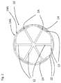
- a support sleeve 1 according to the invention is shown in a top view in an unloaded state.
- the support sleeve 1 has evenly distributed support ribs 2, with a spring segment 3 in the form of a segment of a circle being arranged on each support rib 2 at its radial end 2A.
- the spring segments 3 are arranged centrally on the respective support ribs 2 and thus form two spring arms 4 and 5.
- Each spring segment 5 and 5 has end segments 6 angled inwards at its two ends 4A and 5A, as seen in the circumferential direction.
- the end segments 6 face their respective adjacent end 5A and 4A and are spaced apart from them in the circumferential direction.
- a support sleeve 10 according to the invention with evenly distributed support ribs 12 is also shown in a plan view.
- the support ribs 12 have secant-shaped support feet 13 on their respective radial ends 12A, on which spring segments 14 formed in the shape of a segment of a circle are arranged.
- Each spring segment 14 has end segments 16 angled inwards at its two ends 14A as seen in the circumferential direction.
- the end segments 15 are spaced apart from their respective neighboring segments in the circumferential direction.
Landscapes
- Engineering & Computer Science (AREA)
- General Engineering & Computer Science (AREA)
- Mechanical Engineering (AREA)
- Chemical & Material Sciences (AREA)
- Combustion & Propulsion (AREA)
- Manufacturing & Machinery (AREA)
- Mutual Connection Of Rods And Tubes (AREA)
Description
- Die Erfindung betrifft eine Verbindungsanordnung für Fluidleitungen, aufweisend ein Ladeluftrohr und eine Stützhülse aus Kunststoff, wobei die Stützhülse speichenartige, radial nach außen weisende Stützrippen aufweist.
- Ladeluftrohre werden aufgrund der einfachen Herstellbarkeit und des geringen Gewichts heute oft als Blasformteil ausgeführt. Dabei sind auch geringe Wandstärken erreichbar.
- Problematisch sind diese geringen Wandstärken im Bereich der Anschlüsse, da die Festigkeit der Rohrwand meist nicht ausreicht, um weitere Fluidleitungen an das Rohr anzuschließen. Dies geschieht meist durch das Aufschieben eines Schlauches auf das Endstück des Ladeluftrohres und anschließender Verklemmung mit Spannhülsen oder Schellen. Ohne Verstärkung des Endes des Ladeluftrohres würde dieses bei der Verklemmung zusammengedrückt.
- Die Endstücke sind daher meist mit einer metallischen Stützhülse verstärkt. Dies verursacht teilweise erheblichen Aufwand, da das Endstück des Ladeluftrohres auf ein definiertes Maß aufgespindelt werden muss, um die metallene Hülse in das Innere des Rohres einpressen zu können. Da das thermische Verhalten der Kunststoffe des Ladeluftrohres und des Metalles der Stützhülse unterschiedlich sind, muss die Hülse auch gegen ein Herausfallen aus dem Rohrende gesichert sein. Dazu kann beispielsweise der Kunststoff am Rohrende nochmals aufgeschmolzen und nach innen gedrückt werden. So entsteht eine Herausfallsperre.
- Derartige Stützhülsen sind meist relativ schwer und wegen des unterschiedlichen Temperaturverhaltens nicht optimal einsetzbar.
- In der
DE 10 2017 208 444 A1 ist eine Stützhülse offenbart, die diesen Nachteil dadurch ausgleicht, dass die Stützhülse aus Kunststoff ausgebildet ist und Stützrippen aufweist, die für die nötige Steifigkeit und Festigkeit der Stützhülse sorgen. DieUS 2006 278 192 A1 offenbart ein in ein Luftansaugrohr einsetzbares Drucklufthorn in Form eines Kegelstumpfes, der von einem flexiblen Bügel mit verstellbaren Durchmesser umgeben ist. - Aus dem
EP 0 212 883 A2 ist ein weiteres Beispiel bekannt. - Da bei blasgeformten Rohren teilweise nicht unerhebliche Wandstärkenunterschiede auftreten können, ist es teilweise schwierig, eine solche Stützhülse in ein entsprechendes Rohrende einzuschieben und ggf. dort so festzulegen, dass sie nicht wieder herausfällt. Der Erfindung liegt die Aufgabe zugrunde, eine einfache und kostengünstige Verbindungsanordnung für Fluidleitungen zu schaffen, die eine sichere Montage fluidführender Bauteile ermöglicht.
- Diese Aufgabe wird dadurch gelöst, dass die Stützrippen der Stützhülse an ihren radialen Außenenden federnde Stützbereiche aufweisen.
- Federnde Stützbereiche sind aufgrund ihrer Elastizität der Geometrie eines Ladeluftrohr-Endes gut anpassbar. So können die federnden Stützbereiche beim Einstecken zusammengedrückt werden, so dass ein leichtes Einstecken möglich ist und können in ihrer vorgesehenen Position wieder Ausfedern, so dass ein sicheres Abstützen des Ladeluftrohres bei gleichzeitiger Sicherheit gegen Herausfallen gegeben ist. Erfindungsgemäß sind die federnden Stützbereiche als kreissegmentartig ausgebildete Federsegmente ausgebildet, wobei jedem Federsegment ein Stützrippenende zugeordnet ist und das Stützrippenende mittig an dem Federsegment angreift, so dass jedes Federsegment zwei Federarme ausbildet.
- Die Federarme jedes Federsegmentes sind leicht herstellbar und in Ihrer Geometrie so vorbestimmbar, dass sie nahezu beliebigen Geometrieanforderungen in Zusammenhang mit blasgeformten Ladeluftrohr-Enden genügen können.
- In einer Weiterbildung der Erfindung sind die kreissegmentartigen Federsegmente jeweils mit einem sekantenartigen geraden Stützfuß verstärkt, wobei jeder Stützfuß an jeweils einem Stützrippenende angeordnet ist und jeweils an den in Umfangsrichtung gesehenen Enden jeweils mit einem Federsegment verbunden ist, so dass zwischen Stützfuß und Federsegment ein in radialer Ausdehnung sich von Null bis zu einem vorbestimmten Scheitelwert ändernder Zwischenraum ausbildbar ist.
- Durch diese Geometrie entstehen in radialer Richtung recht steife, tragfähige Traggebilde, die aber auch gute Federeigenschaften aufweisen, so dass eine derartig ausgebildete Stützhülse sowohl gut an die Geometrie der jeweiligen Ladeluftrohr-Enden anpassbar ist als auch eine hohe Stützwirkung gewährleistet.
- In einer Weiterbildung der Erfindung ist an jedem Federsegment an jedem seiner in Umfangsrichtung gesehenen Enden ein nach radial Innen abgewinkeltes Endsegment vorbestimmter Länge ausgebildet.
- Die Federsegmente werden in eingebautem Zustand der erfindungsgemäßen Stützhülse beim Belasten durch einen auf dem Ladeluftrohr angeordneten Spannring bestimmungsgemäß federnd radial nach Innen verformt. Dabei kann es wegen der damit einhergehenden Durchmesserverringerung dazu kommen, dass sich die Enden aneinander angrenzender Federelemente übereinander schieben und dabei eine unerwünschte Geometrie annehmen. Die nach Innen abgewinkelten Endsegmente verhindern dies, da sie aufgrund ihrer vorbestimmten Länge nach innen ragen und zwar aneinander stoßen, sich aber nicht übereinander schieben können.
- In einer Weiterbildung ist die Stützhülse als Spritzgußteil hergestellt.
- Das Spritzgießverfahren ist für Kunststoffteile der erfindungsgemäßen Form besonders gut geeignet
- In einer Weiterbildung der Erfindung ist die Stützhülse aus verschiedenen Kunststoffarten ausgebildet.
- Verschiedene Kunststoffarten ermöglichen, bei den einzelnen Komponenten der erfindungsgemäßen Stützhülsen verschiedene Festigkeiten zu erreichen.
- In einer Weiterbildung der Erfindung sind die Stützrippen der Stützhülse aus einem gegenüber den federnden Stützbereichen höherfesten Kunststoff ausgebildet.
- Durch einen höherfesten Kunststoff ist ein besonders sparsamer Materialeinsatz möglich. Die größere Sprödigkeit derartiger Werkstoffe sind dadurch, dass sie nur in den Stützrippe eingesetzt werden, nicht störend.
- In einer Weiterbildung der Erfindung ist die Stützhülsen mittels des 3D-Druckes hergestellt.
- Das 3D-Druckverfahren ermöglicht auf besonders einfache Weise den Einsatz verschiedener Kunststoffarten in einem Bauteil.
- Anhand der Zeichnung wird ein Beispiel der Erfindung näher erläutert. Es zeigt
- die
Fig. 1 zeigt eine Stützhülse mit gleichmäßig verteilten Stützrippen und kreissegmentartig ausgebildeten Federsegmenten in unbelasteten Zustand, - die
Fig. 2 eine Stützhülse mit gleichmäßig verteilten Stützrippen und Stützfüßen und kreissegmentartig ausgebildeten Federsegmenten mit nach Innen abgewinkelten Endsegmenten in unbelasteten Zustand und - die
Fig. 3 die Stützhülse ausFig. 2 in belastetem Zustand - In der
Fig. 1 ist eine erfindungsgemäße Stützhülse 1 in unbelastetem Zustand in einer Draufsicht gezeigt. Die Stützhülse 1 weist gleichmäßig verteilte Stützrippen 2 auf, wobei an jeder Stützrippe 2 an seinem radialen Ende 2A ein kreissegmentartig ausgebildetes Federsegment 3 angeordnet ist. Die Federsegmente 3 sind mittig an den jeweiligen Stützrippen 2 angeordnet und bilden dadurch jeweils zwei Federarme 4 und 5. Jedes Federsegment 5 und 5 weist an seinen in Umfangsrichtung gesehen beiden Enden 4A und 5A nach Innen abgewinkelte Endsegmente 6 auf. Die Endsegmente 6 sind ihrem jeweiligen benachbarten Ende 5A sowie 4A zugewandt und sind in Umfangsrichtung von diesen beabstandet. - In der
Fig. 2 ist eine erfindungsgemäße Stützhülse 10 mit gleichmäßig verteilten Stützrippen 12 ebenfalls in einer Draufsicht gezeigt. Die Stützrippen 12 tragen an ihren jeweiligen radialen Enden 12A sekantenartig ausgebildete Stützfüße 13, an denen jeweils kreissegmentartig ausgebildeten Federsegmenten 14 angeordnet sind. Jedes Federsegment 14 weist an seinen in Umfangsrichtung gesehen beiden Enden 14A nach Innen abgewinkelte Endsegmente 16 auf. Die Endsegmente 15 sind in Umfangsrichtung von ihren jeweiligen Nachbarsegmenten beabstandet. - In der
Fig. 3 ist die Stützhülse 10 gemäßFig. 2 in belastetem Zustand gezeigt. Ein Ladeluftrohr mit Spannring ist auch hier nicht dargestellt. Durch die radiale Belastung sind sowohl die Stützfüße 13 als auch die Federsegmente 14 radial nach Innen verformt. Dabei stoßen benachbarte Endsegmente 15 jeweils zusammen. Durch die Abwinkelung der Endsegmente 15 ist ein Übereinanderschieben der Federsegmente 14 ausgeschlossen. - Durch die Erfindungsgemäße Lösung ist sowohl ein fester Halt der Stützhülsen in einem Ladeluftrohr in unbelastetem Zustand als auch eine steife, das unzulässige Zusammenpressen von Ladeluftrohren verhindernde Stützhülse bei Belastung gegeben.
-
- 1
- Stützhülse
- 2
- Stützrippen der Stützhülse 1
- 2A
- radiale Enden der Stützrippen 2
- 3
- Federsegmente an den Stützrippen 3
- 4, 5
- Federarme der Federelemente 3
- 4A, 5A
- Enden der Federarme 4, 5
- 6
- Endsegmente der Federelemente 4, 5
- 10
- Stützhülse
- 12
- Stützrippen der Stützhülse 10
- 12A
- radiale Enden der Stützrippen 12
- 13
- Stützfüße an der Stützrippen 12
- 14
- Federsegmente
- 14A
- Enden der Federsegmente 14
- 16
- Endsegmente der Federelemente 14
Claims (7)
- Verbindungsanordnung für Fluidleitungen, aufweisend ein Ladeluftrohr und mindestens eine Stützhülse (1) aus Kunststoff, wobei die Stützhülse (1) speichenartige, radial nach außen weisende Stützrippen (2, 12) aufweist, wobei die Stützrippen (2, 12) der Stützhülse (1) an ihren radialen Außenenden (2A, 12A) federnde Stützbereiche (3, 14) aufweisen, dadurch gekennzeichnet, dass die federnden Stützbereiche (3) als kreissegmentartig ausgebildete Federsegmente (3) ausgebildet sind, wobei jedem Federsegment (3) ein Stützrippenende (2A) zugeordnet ist und das Stützrippenende (2A) mittig an dem Federsegment (3) angreift, so dass jedes Federsegment (3) zwei Federarme (4, 5) ausbildet.
- Verbindungsanordnung nach Anspruch 1, dadurch gekennzeichnet, dass die kreissegmentartigen Federsegmente (14) jeweils mit einem sekantenartigen geraden Stützfuß (13) verstärkt sind, wobei jeder Stützfuß (13) an jeweils einem Stützrippenende (12A) angeordnet ist und jeweils an den in Umfangsrichtung gesehenen Enden (14A) jeweils mit einem Federsegment (14) verbunden ist, so dass zwischen Stützfuß (13) und Federsegment (14) ein in radialer Ausdehnung sich von Null bis zu einem vorbestimmten Scheitelwert ändernder Zwischenraum ausbildbar ist.
- Verbindungsanordnung nach Anspruch 1 oder 2, dadurch gekennzeichnet, dass an jedem Federsegment (3, 14) an jedem seiner in Umfangsrichtung gesehenen Enden (4A, 5A, 14A) ein nach radial Innen abgewinkeltes Endsegment (6, 16) vorbestimmter Länge ausgebildet ist.
- Verbindungsanordnung nach mindestens einem der Ansprüche 1 bis 3, dadurch gekennzeichnet, dass die Stützhülse (1) als Spritzgußteil hergestellt ist.
- Verbindungsanordnung nach mindestens einem der Ansprüche 1 bis 3, dadurch gekennzeichnet, dass die Stützhülse (1) aus verschiedenen Kunststoffarten ausgebildet ist.
- Verbindungsanordnung nach Anspruch 5, dadurch gekennzeichnet, dass die Stützrippen (2, 12) der Stützhülse (1, 10) aus einem gegenüber den federnden Stützbereichen (3, 14) höherfesten Kunststoff ausgebildet sind.
- Verbindungsanordnung nach Anspruch 5 oder 6, dadurch gekennzeichnet, dass die Stützhülse (1) mittels des 3D-Druckes hergestellt ist.
Applications Claiming Priority (1)
| Application Number | Priority Date | Filing Date | Title |
|---|---|---|---|
| DE102019210937.3A DE102019210937A1 (de) | 2019-07-24 | 2019-07-24 | Verbindungsanordnung für Fluidleitungen |
Publications (2)
| Publication Number | Publication Date |
|---|---|
| EP3770416A1 EP3770416A1 (de) | 2021-01-27 |
| EP3770416B1 true EP3770416B1 (de) | 2024-10-16 |
Family
ID=71083347
Family Applications (1)
| Application Number | Title | Priority Date | Filing Date |
|---|---|---|---|
| EP20178924.5A Active EP3770416B1 (de) | 2019-07-24 | 2020-06-09 | Verbindungsanordnung für fluidleitungen |
Country Status (2)
| Country | Link |
|---|---|
| EP (1) | EP3770416B1 (de) |
| DE (1) | DE102019210937A1 (de) |
Citations (1)
| Publication number | Priority date | Publication date | Assignee | Title |
|---|---|---|---|---|
| EP0212883A2 (de) * | 1985-08-02 | 1987-03-04 | John Derek Guest | Rohrkupplungen |
Family Cites Families (6)
| Publication number | Priority date | Publication date | Assignee | Title |
|---|---|---|---|---|
| DE4201677C1 (de) * | 1992-01-23 | 1992-12-03 | Mercedes-Benz Aktiengesellschaft, 7000 Stuttgart, De | |
| US7614379B2 (en) * | 2005-05-23 | 2009-11-10 | Leo Now | Air horn for efficient fluid intake |
| DE102009011769A1 (de) * | 2009-03-09 | 2010-09-16 | Mann + Hummel Gmbh | Schellenverbindung eines Luftkanals |
| DE102017208432A1 (de) * | 2017-05-18 | 2018-11-22 | Contitech Mgw Gmbh | Verbindungsanordnung für Fluidleitungen |
| DE102017208439A1 (de) * | 2017-05-18 | 2018-11-22 | Contitech Mgw Gmbh | Verbindungsanordnung für Fluidleitungen |
| DE102017208444A1 (de) | 2017-05-18 | 2018-11-22 | Contitech Mgw Gmbh | Verbindungsanordnung für Fluidleitungen |
-
2019
- 2019-07-24 DE DE102019210937.3A patent/DE102019210937A1/de active Pending
-
2020
- 2020-06-09 EP EP20178924.5A patent/EP3770416B1/de active Active
Patent Citations (1)
| Publication number | Priority date | Publication date | Assignee | Title |
|---|---|---|---|---|
| EP0212883A2 (de) * | 1985-08-02 | 1987-03-04 | John Derek Guest | Rohrkupplungen |
Also Published As
| Publication number | Publication date |
|---|---|
| DE102019210937A1 (de) | 2021-01-28 |
| EP3770416A1 (de) | 2021-01-27 |
Similar Documents
| Publication | Publication Date | Title |
|---|---|---|
| EP1835144B1 (de) | Anschluss für ein rohrförmiges Luftführungselement an einem Turbolader | |
| EP1746294B1 (de) | Steckkupplung mit dreidimensionaler Ausgleichsbewegung in Plattenmontage | |
| DE9307262U1 (de) | Schiebehülsen-Verbindung für Kunststoffrohre | |
| EP2793334A2 (de) | Kabelverschraubung mit integralem Gelenk | |
| EP2904301B1 (de) | Halteriegel für eine muffenrohrverbindung | |
| EP2428696A1 (de) | Federelement | |
| DE102008043348A1 (de) | Anordnung mit zumindest zwei luftführenden Teilen und einer dazwischen angeordneten Dichtung sowie Hausgerät mit einer derartigen Anordnung | |
| EP3369609B1 (de) | Stromschienensystem | |
| EP3770416B1 (de) | Verbindungsanordnung für fluidleitungen | |
| EP3667148A1 (de) | Längenkompensator | |
| DE4118577C2 (de) | Luftfeder mit einem Schlauchrollbalg aus elastomerem Werkstoff | |
| EP3404305B1 (de) | Verbindungsanordnung für fluidleitungen | |
| WO2009015927A1 (de) | Pressfitting fuer ein rohr, insbesondere kunststoffrohr oder kunststoff-metall-verbundrohr | |
| EP3667144B1 (de) | Bausatz zur herstellung einer verbindung zwischen zwei verbundrohren für klima- und lüftungstechnik | |
| EP1306601B1 (de) | Pressfitting für den Anschluss mindestens eines Rohres | |
| EP2487398B1 (de) | Rohr- oder Schlauchanschluss | |
| EP2513389A1 (de) | Teleskopierbare baustütze | |
| WO2015172781A1 (de) | Gleitlager-drehverbindung | |
| DE102018133355B4 (de) | Ringförmige Trägerstruktur und Zusammenbau für Leichtbauanwendungen | |
| EP1980780B1 (de) | Dichtmuffe für einen Rohrverbinder | |
| DE102012005943A1 (de) | Vorrichtung zum Verbinden von zwei Rundkörpern mit unterschiedlichen Außendurchmessern | |
| DE102017003903A1 (de) | Kupplungsvorrichtung zur Drehmomentübertragung | |
| EP3404249A1 (de) | Verbindungsanordnung für fluidleitungen | |
| EP4051943A1 (de) | Fluidleitungskupplung | |
| WO2018036936A1 (de) | Sicherungskralle |
Legal Events
| Date | Code | Title | Description |
|---|---|---|---|
| PUAI | Public reference made under article 153(3) epc to a published international application that has entered the european phase |
Free format text: ORIGINAL CODE: 0009012 |
|
| STAA | Information on the status of an ep patent application or granted ep patent |
Free format text: STATUS: THE APPLICATION HAS BEEN PUBLISHED |
|
| AK | Designated contracting states |
Kind code of ref document: A1 Designated state(s): AL AT BE BG CH CY CZ DE DK EE ES FI FR GB GR HR HU IE IS IT LI LT LU LV MC MK MT NL NO PL PT RO RS SE SI SK SM TR |
|
| AX | Request for extension of the european patent |
Extension state: BA ME |
|
| STAA | Information on the status of an ep patent application or granted ep patent |
Free format text: STATUS: REQUEST FOR EXAMINATION WAS MADE |
|
| 17P | Request for examination filed |
Effective date: 20210727 |
|
| RBV | Designated contracting states (corrected) |
Designated state(s): AL AT BE BG CH CY CZ DE DK EE ES FI FR GB GR HR HU IE IS IT LI LT LU LV MC MK MT NL NO PL PT RO RS SE SI SK SM TR |
|
| STAA | Information on the status of an ep patent application or granted ep patent |
Free format text: STATUS: EXAMINATION IS IN PROGRESS |
|
| 17Q | First examination report despatched |
Effective date: 20221018 |
|
| GRAP | Despatch of communication of intention to grant a patent |
Free format text: ORIGINAL CODE: EPIDOSNIGR1 |
|
| STAA | Information on the status of an ep patent application or granted ep patent |
Free format text: STATUS: GRANT OF PATENT IS INTENDED |
|
| INTG | Intention to grant announced |
Effective date: 20240612 |
|
| RAP1 | Party data changed (applicant data changed or rights of an application transferred) |
Owner name: CONTITECH TECHNO-CHEMIE GMBH |
|
| P01 | Opt-out of the competence of the unified patent court (upc) registered |
Free format text: CASE NUMBER: APP_41303/2024 Effective date: 20240712 |
|
| GRAS | Grant fee paid |
Free format text: ORIGINAL CODE: EPIDOSNIGR3 |
|
| GRAA | (expected) grant |
Free format text: ORIGINAL CODE: 0009210 |
|
| STAA | Information on the status of an ep patent application or granted ep patent |
Free format text: STATUS: THE PATENT HAS BEEN GRANTED |
|
| AK | Designated contracting states |
Kind code of ref document: B1 Designated state(s): AL AT BE BG CH CY CZ DE DK EE ES FI FR GB GR HR HU IE IS IT LI LT LU LV MC MK MT NL NO PL PT RO RS SE SI SK SM TR |
|
| REG | Reference to a national code |
Ref country code: GB Ref legal event code: FG4D Free format text: NOT ENGLISH |
|
| REG | Reference to a national code |
Ref country code: CH Ref legal event code: EP Ref country code: DE Ref legal event code: R096 Ref document number: 502020009485 Country of ref document: DE |
|
| REG | Reference to a national code |
Ref country code: IE Ref legal event code: FG4D Free format text: LANGUAGE OF EP DOCUMENT: GERMAN |
|
| REG | Reference to a national code |
Ref country code: LT Ref legal event code: MG9D |
|
| REG | Reference to a national code |
Ref country code: NL Ref legal event code: MP Effective date: 20241016 |
|
| PG25 | Lapsed in a contracting state [announced via postgrant information from national office to epo] |
Ref country code: NL Free format text: LAPSE BECAUSE OF FAILURE TO SUBMIT A TRANSLATION OF THE DESCRIPTION OR TO PAY THE FEE WITHIN THE PRESCRIBED TIME-LIMIT Effective date: 20241016 |
|
| PG25 | Lapsed in a contracting state [announced via postgrant information from national office to epo] |
Ref country code: NL Free format text: LAPSE BECAUSE OF FAILURE TO SUBMIT A TRANSLATION OF THE DESCRIPTION OR TO PAY THE FEE WITHIN THE PRESCRIBED TIME-LIMIT Effective date: 20241016 |
|
| PG25 | Lapsed in a contracting state [announced via postgrant information from national office to epo] |
Ref country code: HR Free format text: LAPSE BECAUSE OF FAILURE TO SUBMIT A TRANSLATION OF THE DESCRIPTION OR TO PAY THE FEE WITHIN THE PRESCRIBED TIME-LIMIT Effective date: 20241016 Ref country code: IS Free format text: LAPSE BECAUSE OF FAILURE TO SUBMIT A TRANSLATION OF THE DESCRIPTION OR TO PAY THE FEE WITHIN THE PRESCRIBED TIME-LIMIT Effective date: 20250216 Ref country code: PT Free format text: LAPSE BECAUSE OF FAILURE TO SUBMIT A TRANSLATION OF THE DESCRIPTION OR TO PAY THE FEE WITHIN THE PRESCRIBED TIME-LIMIT Effective date: 20250217 |
|
| PG25 | Lapsed in a contracting state [announced via postgrant information from national office to epo] |
Ref country code: FI Free format text: LAPSE BECAUSE OF FAILURE TO SUBMIT A TRANSLATION OF THE DESCRIPTION OR TO PAY THE FEE WITHIN THE PRESCRIBED TIME-LIMIT Effective date: 20241016 |
|
| PG25 | Lapsed in a contracting state [announced via postgrant information from national office to epo] |
Ref country code: BG Free format text: LAPSE BECAUSE OF FAILURE TO SUBMIT A TRANSLATION OF THE DESCRIPTION OR TO PAY THE FEE WITHIN THE PRESCRIBED TIME-LIMIT Effective date: 20241016 |
|
| PG25 | Lapsed in a contracting state [announced via postgrant information from national office to epo] |
Ref country code: ES Free format text: LAPSE BECAUSE OF FAILURE TO SUBMIT A TRANSLATION OF THE DESCRIPTION OR TO PAY THE FEE WITHIN THE PRESCRIBED TIME-LIMIT Effective date: 20241016 |
|
| PG25 | Lapsed in a contracting state [announced via postgrant information from national office to epo] |
Ref country code: NO Free format text: LAPSE BECAUSE OF FAILURE TO SUBMIT A TRANSLATION OF THE DESCRIPTION OR TO PAY THE FEE WITHIN THE PRESCRIBED TIME-LIMIT Effective date: 20250116 |
|
| PG25 | Lapsed in a contracting state [announced via postgrant information from national office to epo] |
Ref country code: LV Free format text: LAPSE BECAUSE OF FAILURE TO SUBMIT A TRANSLATION OF THE DESCRIPTION OR TO PAY THE FEE WITHIN THE PRESCRIBED TIME-LIMIT Effective date: 20241016 Ref country code: GR Free format text: LAPSE BECAUSE OF FAILURE TO SUBMIT A TRANSLATION OF THE DESCRIPTION OR TO PAY THE FEE WITHIN THE PRESCRIBED TIME-LIMIT Effective date: 20250117 |
|
| PG25 | Lapsed in a contracting state [announced via postgrant information from national office to epo] |
Ref country code: PL Free format text: LAPSE BECAUSE OF FAILURE TO SUBMIT A TRANSLATION OF THE DESCRIPTION OR TO PAY THE FEE WITHIN THE PRESCRIBED TIME-LIMIT Effective date: 20241016 |
|
| PG25 | Lapsed in a contracting state [announced via postgrant information from national office to epo] |
Ref country code: RS Free format text: LAPSE BECAUSE OF FAILURE TO SUBMIT A TRANSLATION OF THE DESCRIPTION OR TO PAY THE FEE WITHIN THE PRESCRIBED TIME-LIMIT Effective date: 20250116 |
|
| PG25 | Lapsed in a contracting state [announced via postgrant information from national office to epo] |
Ref country code: SM Free format text: LAPSE BECAUSE OF FAILURE TO SUBMIT A TRANSLATION OF THE DESCRIPTION OR TO PAY THE FEE WITHIN THE PRESCRIBED TIME-LIMIT Effective date: 20241016 |
|
| PGFP | Annual fee paid to national office [announced via postgrant information from national office to epo] |
Ref country code: DE Payment date: 20250630 Year of fee payment: 6 |
|
| PG25 | Lapsed in a contracting state [announced via postgrant information from national office to epo] |
Ref country code: DK Free format text: LAPSE BECAUSE OF FAILURE TO SUBMIT A TRANSLATION OF THE DESCRIPTION OR TO PAY THE FEE WITHIN THE PRESCRIBED TIME-LIMIT Effective date: 20241016 |
|
| REG | Reference to a national code |
Ref country code: DE Ref legal event code: R097 Ref document number: 502020009485 Country of ref document: DE |
|
| PG25 | Lapsed in a contracting state [announced via postgrant information from national office to epo] |
Ref country code: EE Free format text: LAPSE BECAUSE OF FAILURE TO SUBMIT A TRANSLATION OF THE DESCRIPTION OR TO PAY THE FEE WITHIN THE PRESCRIBED TIME-LIMIT Effective date: 20241016 |
|
| PG25 | Lapsed in a contracting state [announced via postgrant information from national office to epo] |
Ref country code: RO Free format text: LAPSE BECAUSE OF FAILURE TO SUBMIT A TRANSLATION OF THE DESCRIPTION OR TO PAY THE FEE WITHIN THE PRESCRIBED TIME-LIMIT Effective date: 20241016 |
|
| PG25 | Lapsed in a contracting state [announced via postgrant information from national office to epo] |
Ref country code: SK Free format text: LAPSE BECAUSE OF FAILURE TO SUBMIT A TRANSLATION OF THE DESCRIPTION OR TO PAY THE FEE WITHIN THE PRESCRIBED TIME-LIMIT Effective date: 20241016 |
|
| PG25 | Lapsed in a contracting state [announced via postgrant information from national office to epo] |
Ref country code: CZ Free format text: LAPSE BECAUSE OF FAILURE TO SUBMIT A TRANSLATION OF THE DESCRIPTION OR TO PAY THE FEE WITHIN THE PRESCRIBED TIME-LIMIT Effective date: 20241016 |
|
| PG25 | Lapsed in a contracting state [announced via postgrant information from national office to epo] |
Ref country code: IT Free format text: LAPSE BECAUSE OF FAILURE TO SUBMIT A TRANSLATION OF THE DESCRIPTION OR TO PAY THE FEE WITHIN THE PRESCRIBED TIME-LIMIT Effective date: 20241016 |
|
| PLBE | No opposition filed within time limit |
Free format text: ORIGINAL CODE: 0009261 |
|
| STAA | Information on the status of an ep patent application or granted ep patent |
Free format text: STATUS: NO OPPOSITION FILED WITHIN TIME LIMIT |
|
| PG25 | Lapsed in a contracting state [announced via postgrant information from national office to epo] |
Ref country code: SE Free format text: LAPSE BECAUSE OF FAILURE TO SUBMIT A TRANSLATION OF THE DESCRIPTION OR TO PAY THE FEE WITHIN THE PRESCRIBED TIME-LIMIT Effective date: 20241016 |
|
| 26N | No opposition filed |
Effective date: 20250717 |
|
| REG | Reference to a national code |
Ref country code: CH Ref legal event code: H13 Free format text: ST27 STATUS EVENT CODE: U-0-0-H10-H13 (AS PROVIDED BY THE NATIONAL OFFICE) Effective date: 20260127 |
|
| PG25 | Lapsed in a contracting state [announced via postgrant information from national office to epo] |
Ref country code: MC Free format text: LAPSE BECAUSE OF FAILURE TO SUBMIT A TRANSLATION OF THE DESCRIPTION OR TO PAY THE FEE WITHIN THE PRESCRIBED TIME-LIMIT Effective date: 20241016 |
|
| PG25 | Lapsed in a contracting state [announced via postgrant information from national office to epo] |
Ref country code: LU Free format text: LAPSE BECAUSE OF NON-PAYMENT OF DUE FEES Effective date: 20250609 |
|
| GBPC | Gb: european patent ceased through non-payment of renewal fee |
Effective date: 20250609 |
|
| REG | Reference to a national code |
Ref country code: BE Ref legal event code: MM Effective date: 20250630 |