EP3404305B1 - Verbindungsanordnung für fluidleitungen - Google Patents
Verbindungsanordnung für fluidleitungen Download PDFInfo
- Publication number
- EP3404305B1 EP3404305B1 EP18157541.6A EP18157541A EP3404305B1 EP 3404305 B1 EP3404305 B1 EP 3404305B1 EP 18157541 A EP18157541 A EP 18157541A EP 3404305 B1 EP3404305 B1 EP 3404305B1
- Authority
- EP
- European Patent Office
- Prior art keywords
- air pipe
- fluid lines
- charge air
- connecting piece
- connector piece
- Prior art date
- Legal status (The legal status is an assumption and is not a legal conclusion. Google has not performed a legal analysis and makes no representation as to the accuracy of the status listed.)
- Active
Links
- 239000012530 fluid Substances 0.000 title claims description 7
- 239000004033 plastic Substances 0.000 claims description 5
- 229920003023 plastic Polymers 0.000 claims description 5
- 238000001746 injection moulding Methods 0.000 claims description 4
- 239000011324 bead Substances 0.000 description 7
- 238000003466 welding Methods 0.000 description 6
- 238000004519 manufacturing process Methods 0.000 description 3
- 238000003780 insertion Methods 0.000 description 2
- 230000037431 insertion Effects 0.000 description 2
- 239000002184 metal Substances 0.000 description 2
- 230000004888 barrier function Effects 0.000 description 1
- 238000000071 blow moulding Methods 0.000 description 1
- 238000002485 combustion reaction Methods 0.000 description 1
- 238000000034 method Methods 0.000 description 1
- 230000002787 reinforcement Effects 0.000 description 1
- 239000012815 thermoplastic material Substances 0.000 description 1
Images

Classifications
-
- F—MECHANICAL ENGINEERING; LIGHTING; HEATING; WEAPONS; BLASTING
- F16—ENGINEERING ELEMENTS AND UNITS; GENERAL MEASURES FOR PRODUCING AND MAINTAINING EFFECTIVE FUNCTIONING OF MACHINES OR INSTALLATIONS; THERMAL INSULATION IN GENERAL
- F16L—PIPES; JOINTS OR FITTINGS FOR PIPES; SUPPORTS FOR PIPES, CABLES OR PROTECTIVE TUBING; MEANS FOR THERMAL INSULATION IN GENERAL
- F16L47/00—Connecting arrangements or other fittings specially adapted to be made of plastics or to be used with pipes made of plastics
- F16L47/02—Welded joints; Adhesive joints
-
- B—PERFORMING OPERATIONS; TRANSPORTING
- B29—WORKING OF PLASTICS; WORKING OF SUBSTANCES IN A PLASTIC STATE IN GENERAL
- B29C—SHAPING OR JOINING OF PLASTICS; SHAPING OF MATERIAL IN A PLASTIC STATE, NOT OTHERWISE PROVIDED FOR; AFTER-TREATMENT OF THE SHAPED PRODUCTS, e.g. REPAIRING
- B29C65/00—Joining or sealing of preformed parts, e.g. welding of plastics materials; Apparatus therefor
- B29C65/02—Joining or sealing of preformed parts, e.g. welding of plastics materials; Apparatus therefor by heating, with or without pressure
- B29C65/06—Joining or sealing of preformed parts, e.g. welding of plastics materials; Apparatus therefor by heating, with or without pressure using friction, e.g. spin welding
-
- B—PERFORMING OPERATIONS; TRANSPORTING
- B29—WORKING OF PLASTICS; WORKING OF SUBSTANCES IN A PLASTIC STATE IN GENERAL
- B29C—SHAPING OR JOINING OF PLASTICS; SHAPING OF MATERIAL IN A PLASTIC STATE, NOT OTHERWISE PROVIDED FOR; AFTER-TREATMENT OF THE SHAPED PRODUCTS, e.g. REPAIRING
- B29C66/00—General aspects of processes or apparatus for joining preformed parts
- B29C66/01—General aspects dealing with the joint area or with the area to be joined
- B29C66/05—Particular design of joint configurations
- B29C66/10—Particular design of joint configurations particular design of the joint cross-sections
- B29C66/12—Joint cross-sections combining only two joint-segments; Tongue and groove joints; Tenon and mortise joints; Stepped joint cross-sections
- B29C66/124—Tongue and groove joints
-
- B—PERFORMING OPERATIONS; TRANSPORTING
- B29—WORKING OF PLASTICS; WORKING OF SUBSTANCES IN A PLASTIC STATE IN GENERAL
- B29C—SHAPING OR JOINING OF PLASTICS; SHAPING OF MATERIAL IN A PLASTIC STATE, NOT OTHERWISE PROVIDED FOR; AFTER-TREATMENT OF THE SHAPED PRODUCTS, e.g. REPAIRING
- B29C66/00—General aspects of processes or apparatus for joining preformed parts
- B29C66/50—General aspects of joining tubular articles; General aspects of joining long products, i.e. bars or profiled elements; General aspects of joining single elements to tubular articles, hollow articles or bars; General aspects of joining several hollow-preforms to form hollow or tubular articles
- B29C66/51—Joining tubular articles, profiled elements or bars; Joining single elements to tubular articles, hollow articles or bars; Joining several hollow-preforms to form hollow or tubular articles
- B29C66/53—Joining single elements to tubular articles, hollow articles or bars
- B29C66/534—Joining single elements to open ends of tubular or hollow articles or to the ends of bars
- B29C66/5344—Joining single elements to open ends of tubular or hollow articles or to the ends of bars said single elements being substantially annular, i.e. of finite length, e.g. joining flanges to tube ends
-
- B—PERFORMING OPERATIONS; TRANSPORTING
- B29—WORKING OF PLASTICS; WORKING OF SUBSTANCES IN A PLASTIC STATE IN GENERAL
- B29C—SHAPING OR JOINING OF PLASTICS; SHAPING OF MATERIAL IN A PLASTIC STATE, NOT OTHERWISE PROVIDED FOR; AFTER-TREATMENT OF THE SHAPED PRODUCTS, e.g. REPAIRING
- B29C66/00—General aspects of processes or apparatus for joining preformed parts
- B29C66/70—General aspects of processes or apparatus for joining preformed parts characterised by the composition, physical properties or the structure of the material of the parts to be joined; Joining with non-plastics material
- B29C66/73—General aspects of processes or apparatus for joining preformed parts characterised by the composition, physical properties or the structure of the material of the parts to be joined; Joining with non-plastics material characterised by the intensive physical properties of the material of the parts to be joined, by the optical properties of the material of the parts to be joined, by the extensive physical properties of the parts to be joined, by the state of the material of the parts to be joined or by the material of the parts to be joined being a thermoplastic or a thermoset
- B29C66/739—General aspects of processes or apparatus for joining preformed parts characterised by the composition, physical properties or the structure of the material of the parts to be joined; Joining with non-plastics material characterised by the intensive physical properties of the material of the parts to be joined, by the optical properties of the material of the parts to be joined, by the extensive physical properties of the parts to be joined, by the state of the material of the parts to be joined or by the material of the parts to be joined being a thermoplastic or a thermoset characterised by the material of the parts to be joined being a thermoplastic or a thermoset
- B29C66/7392—General aspects of processes or apparatus for joining preformed parts characterised by the composition, physical properties or the structure of the material of the parts to be joined; Joining with non-plastics material characterised by the intensive physical properties of the material of the parts to be joined, by the optical properties of the material of the parts to be joined, by the extensive physical properties of the parts to be joined, by the state of the material of the parts to be joined or by the material of the parts to be joined being a thermoplastic or a thermoset characterised by the material of the parts to be joined being a thermoplastic or a thermoset characterised by the material of at least one of the parts being a thermoplastic
- B29C66/73921—General aspects of processes or apparatus for joining preformed parts characterised by the composition, physical properties or the structure of the material of the parts to be joined; Joining with non-plastics material characterised by the intensive physical properties of the material of the parts to be joined, by the optical properties of the material of the parts to be joined, by the extensive physical properties of the parts to be joined, by the state of the material of the parts to be joined or by the material of the parts to be joined being a thermoplastic or a thermoset characterised by the material of the parts to be joined being a thermoplastic or a thermoset characterised by the material of at least one of the parts being a thermoplastic characterised by the materials of both parts being thermoplastics
-
- F—MECHANICAL ENGINEERING; LIGHTING; HEATING; WEAPONS; BLASTING
- F02—COMBUSTION ENGINES; HOT-GAS OR COMBUSTION-PRODUCT ENGINE PLANTS
- F02M—SUPPLYING COMBUSTION ENGINES IN GENERAL WITH COMBUSTIBLE MIXTURES OR CONSTITUENTS THEREOF
- F02M35/00—Combustion-air cleaners, air intakes, intake silencers, or induction systems specially adapted for, or arranged on, internal-combustion engines
- F02M35/10—Air intakes; Induction systems
- F02M35/10091—Air intakes; Induction systems characterised by details of intake ducts: shapes; connections; arrangements
- F02M35/10144—Connections of intake ducts to each other or to another device
-
- F—MECHANICAL ENGINEERING; LIGHTING; HEATING; WEAPONS; BLASTING
- F02—COMBUSTION ENGINES; HOT-GAS OR COMBUSTION-PRODUCT ENGINE PLANTS
- F02M—SUPPLYING COMBUSTION ENGINES IN GENERAL WITH COMBUSTIBLE MIXTURES OR CONSTITUENTS THEREOF
- F02M35/00—Combustion-air cleaners, air intakes, intake silencers, or induction systems specially adapted for, or arranged on, internal-combustion engines
- F02M35/10—Air intakes; Induction systems
- F02M35/1015—Air intakes; Induction systems characterised by the engine type
- F02M35/10157—Supercharged engines
-
- F—MECHANICAL ENGINEERING; LIGHTING; HEATING; WEAPONS; BLASTING
- F02—COMBUSTION ENGINES; HOT-GAS OR COMBUSTION-PRODUCT ENGINE PLANTS
- F02M—SUPPLYING COMBUSTION ENGINES IN GENERAL WITH COMBUSTIBLE MIXTURES OR CONSTITUENTS THEREOF
- F02M35/00—Combustion-air cleaners, air intakes, intake silencers, or induction systems specially adapted for, or arranged on, internal-combustion engines
- F02M35/10—Air intakes; Induction systems
- F02M35/10314—Materials for intake systems
- F02M35/10321—Plastics; Composites; Rubbers
-
- F—MECHANICAL ENGINEERING; LIGHTING; HEATING; WEAPONS; BLASTING
- F16—ENGINEERING ELEMENTS AND UNITS; GENERAL MEASURES FOR PRODUCING AND MAINTAINING EFFECTIVE FUNCTIONING OF MACHINES OR INSTALLATIONS; THERMAL INSULATION IN GENERAL
- F16L—PIPES; JOINTS OR FITTINGS FOR PIPES; SUPPORTS FOR PIPES, CABLES OR PROTECTIVE TUBING; MEANS FOR THERMAL INSULATION IN GENERAL
- F16L33/00—Arrangements for connecting hoses to rigid members; Rigid hose-connectors, i.e. single members engaging both hoses
-
- B—PERFORMING OPERATIONS; TRANSPORTING
- B29—WORKING OF PLASTICS; WORKING OF SUBSTANCES IN A PLASTIC STATE IN GENERAL
- B29L—INDEXING SCHEME ASSOCIATED WITH SUBCLASS B29C, RELATING TO PARTICULAR ARTICLES
- B29L2031/00—Other particular articles
- B29L2031/24—Pipe joints or couplings
-
- F—MECHANICAL ENGINEERING; LIGHTING; HEATING; WEAPONS; BLASTING
- F02—COMBUSTION ENGINES; HOT-GAS OR COMBUSTION-PRODUCT ENGINE PLANTS
- F02M—SUPPLYING COMBUSTION ENGINES IN GENERAL WITH COMBUSTIBLE MIXTURES OR CONSTITUENTS THEREOF
- F02M35/00—Combustion-air cleaners, air intakes, intake silencers, or induction systems specially adapted for, or arranged on, internal-combustion engines
- F02M35/10—Air intakes; Induction systems
- F02M35/1034—Manufacturing and assembling intake systems
- F02M35/10354—Joining multiple sections together
- F02M35/1036—Joining multiple sections together by welding, bonding or the like
-
- Y—GENERAL TAGGING OF NEW TECHNOLOGICAL DEVELOPMENTS; GENERAL TAGGING OF CROSS-SECTIONAL TECHNOLOGIES SPANNING OVER SEVERAL SECTIONS OF THE IPC; TECHNICAL SUBJECTS COVERED BY FORMER USPC CROSS-REFERENCE ART COLLECTIONS [XRACs] AND DIGESTS
- Y02—TECHNOLOGIES OR APPLICATIONS FOR MITIGATION OR ADAPTATION AGAINST CLIMATE CHANGE
- Y02T—CLIMATE CHANGE MITIGATION TECHNOLOGIES RELATED TO TRANSPORTATION
- Y02T10/00—Road transport of goods or passengers
- Y02T10/10—Internal combustion engine [ICE] based vehicles
- Y02T10/12—Improving ICE efficiencies
Definitions
- the invention relates to a connection arrangement for fluid lines, comprising a connecting piece and a charge air pipe.
- Charge air pipes are often designed as blow molded parts due to their ease of manufacture and low weight. Small wall thicknesses can also be achieved.
- the end pieces are therefore usually reinforced with a metallic support sleeve. This sometimes causes considerable effort, since the end piece of the charge air pipe has to be opened to a defined dimension in order to be able to press the metal sleeve into the interior of the pipe. Since the thermal behavior of the plastics of the charge air pipe and the metal of the support sleeve are different, the sleeve must also be secured against falling out of the pipe end. For this purpose, for example, the plastic at the end of the pipe can be melted again and pressed inwards. This creates a barrier against falling out.
- the support sleeve In addition to the high manufacturing effort, the support sleeve is also relatively heavy and expensive.
- the invention has for its object to provide a simple and inexpensive connection arrangement for fluid lines, which enables safe assembly of fluid-carrying components.
- the connecting piece is designed as a separate component which can be welded onto at least one end of the charge air pipe.
- the connecting piece is made by plastic injection molding.
- Plastic injection molding is an inexpensive and safe manufacturing process that enables a wide range of shapes and ensures high dimensional accuracy.
- the connecting piece has radially arranged support ribs on the inside.
- the support ribs ensure a particularly high stiffness of the connecting piece, so that the wall thickness can be less.
- the connecting piece has a weld-on surface at one axial end, which corresponds to the shape of the end of the charge air tube.
- the welding surface ensures a defined contact with the respective end of the charge air pipes, so that the safety and reproducibility of the welding process is improved.
- the connecting piece has circumferential grooves on its outer lateral surface.
- the circumferential grooves improve the tight fit of other fluid-carrying components that can be pushed and clamped onto the connecting piece.
- the connecting piece has, at its end opposite the welding surface, a circumferential bead which is bevelled in the axial direction and projects radially outwards.
- Such a bead improves the security against axial pulling off of the further fluid-carrying components clamped on the connecting piece.
- the axial bevel serves as an insertion aid to simplify assembly.
- connection piece 1 according to the invention is shown.
- the connector 1 is made of thermoplastic material by injection molding.
- the connecting piece once has a cylindrical base body 2, which has a plurality of grooves 4 on its outer lateral surface 3.
- the grooves 4 serve to make the attachment of further fluid lines, not shown here, more secure to the connecting piece.
- connecting pieces 1 In its inner passage opening 5, connecting pieces 1 have support ribs 6 arranged radially outwards and arranged in a virtually star shape.
- the supporting ribs 6 serve to stiffen the base body 2.
- the Connection piece 1 At its first axial end 7, the Connection piece 1 on a welding surface 8, which is arranged circumferentially around the first end 7 and is aligned axially flat.
- connection piece 1 is shown viewed from its second axial end 9.
- the second end 9 has a circumferential bead 10 arranged around the end 9.
- the bead 10 has a bevel 11 in the direction of the second axial end 9.
- the bevel 11 serves as an insertion aid when installing further fluid lines, not shown here.
- FIG. 3 An assembly of the connection piece 1 with a charge air pipe section 12 is shown.
- the weld surface 8 is welded to the charge air tube section 12 by means of a friction weld, not visible here, in an airtight manner.
- the arrangement according to the invention makes it possible to dispense with a metallic support sleeve in the charge air tube section 12.
Landscapes
- Engineering & Computer Science (AREA)
- Mechanical Engineering (AREA)
- General Engineering & Computer Science (AREA)
- Chemical & Material Sciences (AREA)
- Combustion & Propulsion (AREA)
- Lining Or Joining Of Plastics Or The Like (AREA)
- Injection Moulding Of Plastics Or The Like (AREA)
Description
- Die Erfindung betrifft eine Verbindungsanordnung für Fluidleitungen, aufweisend einen Anschlussstutzen und einen Ladeluftrohr.
- Ladeluftrohre werden aufgrund der einfachen Herstellbarkeit und des geringen Gewichts heute oft als Blasformteil ausgeführt. Dabei sind auch geringe Wandstärken erreichbar.
- Problematisch sind diese geringen Wandstärken im Bereich der Anschlüsse, da die Festigkeit der Rohrwand meist nicht ausreicht, um weitere Fluidleitungen an das Rohr anzuschließen. Dies geschieht meist durch das Aufschieben eines Schlauches auf das Endstück des Ladeluftrohres und anschließender Verklemmung mit Spannhülsen oder Schellen. Ohne Verstärkung des Endes des Ladeluftrohres würde dieses bei der Verklemmung zusammengedrückt.
- Die Endstücke sind daher meist mit einer metallischen Stützhülse verstärkt. Dies verursacht teilweise erheblichen Aufwand, da das Endstück des Ladeluftrohres auf ein definiertes Maß aufgespielt werden muss, um die metallene Hülse in das Innere des Rohres einpressen zu können. Da das thermische Verhalten der Kunststoffe des Ladeluftrohres und des Metalles der Stützhülse unterschiedlich sind, muss die Hülse auch gegen ein herausfallen aus dem Rohrende gesichert sein. Dazu kann beispielsweise der Kunststoff am Rohrende nochmals aufgeschmolzen und nach innen gedrückt werden. So entsteht eine Herausfallsperre.
- Neben dem hohen Fertigungsaufwand ist die Stützhülse auch relativ schwer und teuer.
-
DE10 2015 215 394 A1 offenbart ein Luftleitungsrohr für den Ansaugtrakt eines Verbrennungsmotors. - Der Erfindung liegt die Aufgabe zugrunde, eine einfache und kostengünstige Verbindungsanordnung für Fluidleitungen zu schaffen, die eine sichere Montage fluidführender Bauteile ermöglicht.
- Diese Aufgabe wird dadurch gelöst, dass der Anschlussstutzen als separates Bauteil ausgeführt ist, welches mindestens an einem Ladeluftrohr-Ende anschweißbar ist.
- Separate Bauteile haben den Vorteil, dass mögliche Wandstärken und geometrische Ausgestaltung wesentlich variabler sind, als bei der Herstellung durch Blasformen zusammen mit dem Ladeluftrohr.
- Der Anschlussstutzen ist durch Kunststoff-Spritzgießen hergestellt.
- Das Kunststoff-Spritzgießen ist ein günstiger und sicherer Herstellprozess, der vielfältige Formgebung ermöglicht und eine hohe Maßgenauigkeit gewährleistet.
- Erfindungsgemäß weist der Anschlussstutzen im Inneren radial angeordnete Stützrippen auf.
- Die Stützrippen sorgen für eine besonders hohe Steifigkeit des Anschlussstutzens, sodass die Wandstärke geringer ausfallen kann.
- In einer Weiterbildung der Erfindung weist der Anschlussstutzen an einem axialen Ende eine Anschweißfläche auf, die mit der Form des Endes des Ladeluftrohres korrespondiert.
- Die Anschweissfläche gewährleistet einen definierten Kontakt zu dem jeweiligen Ende der Ladeluftrohre, so dass die Sicherheit und Reproduzierbarkeit des Anschweißprozesses verbessert ist.
- In einer Weiterbildung der Erfindung weist der Anschlussstutzen auf seiner äußeren Mantelfläche umlaufende Rillen auf.
- Die umlaufenden Rillen verbessern den festen Sitz von weiteren fluidführenden Bauteilen, die auf den Anschlussstutzen aufschiebbar und verklemmbar sind.
- In einer Weiterbildung der Erfindung weist der Anschlussstutzen an seinem der Anschweissfläche gegenüberliegenden Ende einen in axialer Richtung angeschrägten, radial nach außen ragenden umlaufenden Wulst auf.
- Ein derartiger Wulst verbessert die Sicherheit gegen axiales Abziehen der weiteren, auf dem Anschlussstutzen festgeklemmten fluidführenden Bauteile. Die axiale Anschrägung dient dabei als Einführhilfe, um die Montage zu vereinfachen.
- Anhand der Zeichnung wird nachstehend ein Beispiel der Erfindung näher erläutert. Es zeigt
-
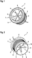
Fig. 1 eine perspektivische Darstellung eines erfindungsgemäßen Anschlussstutzens mit einer an Schweiß fläche, -
Fig. 2 den erfindungsgemäßen Anschlussstutzen mit umlaufenden Wulst und -
Fig. 3 einen Zusammenbau des erfindungsgemäßen Anschlussstutzens mit einem blasgeformten Ladeluft-Rohrabschnitt. - In
Fig. 1 ist ein erfindungsgemäßer Anschlussstutzen 1 gezeigt. Der Anschlussstutzen 1 ist aus thermoplastischem Kunststoff im Spritzgussverfahren hergestellt. - Der Anschlussstutzen einst weist einen zylindrischen Grundkörper 2 auf, der auf seiner äußeren Mantelfläche 3 eine Mehrzahl von Rillen 4 aufweist. Die Rillen 4 dienen dazu, die Befestigung weiterer, hier nicht gezeigter Fluidleitungen auf dem Anschlussstutzen sicherer zu gestalten. In seiner inneren Durchlassöffnung 5 weist Anschlussstutzen 1 radial nach außen weisende, quasi sternförmig angeordnete Stützrippen 6 auf. Die Stützrippen 6 dienen der Versteifung des Grundkörpers 2. An seinem ersten axialen Ende 7 weist der Anschlussstutzen 1 eine Anschweißfläche 8 auf, die umlaufend um das erste Ende 7 herum angeordnet ist und axial plan ausgerichtet ist.
- In
Figur 2 ist der Anschlussstutzen 1 von seinem zweiten axialen Ende 9 aus gesehen dargestellt. Das zweite Ende 9 weist einen umlaufenden um das Ende 9 herum angeordneten Wulst 10 auf. Der Wulst 10 weist in Richtung auf das zweite axiale Ende 9 eine Anschrägung 11 auf. Die Anschrägung 11 dient als Einführhilfe bei der Montage weiterer, hier nicht gezeigter Fluidleitungen. - In
Fig. 3 ist ein Zusammenbau des Anschlussstutzens 1 mit einem Ladeluftrohrabschnitt 12 gezeigt. Die an Schweiß fläche 8 ist mit dem Ladeluftrohrabschnitt 12 mittels einer hier nicht sichtbaren Reibschweißung fest und luftdicht verschweißt. - Durch die erfindungsgemäße Anordnung kann eine metallische Stützhülse im Ladeluft-Rohrabschnitt 12 entfallen.
-
- 1
- Anschlussstutzen
- 2
- Grundkörper des Anschlussstutzens 1
- 3
- Mantelfläche des Grundkörpers 2
- 4
- Rillen auf der Mantelfläche 3
- 5
- Durchlassöffnung des Anschlussstutzens 1
- 6
- Stützrippen
- 7
- Erstes axiales Ende des Anschlussstutzens 1
- 8
- Anschweissfläche
- 9
- Zweites axiales Ende des Anschlussstutzens 1
- 10
- Wulst
- 11
- Anschrägung des Wulstes 10
- 12
- Ladeluftrohrabschnitt
Claims (3)
- Verbindungsanordnung für Fluidleitungen, aufweisend ein Ladeluftrohr (12) und mindestens einen Anschlussstutzen (1), der durch Kunststoff-Spritzgießen hergestellt und als separates Bauteil ausgeführt ist, welches mindestens an einem Ladeluftrohr-Ende (7, 9) anschweissbar ist, dadurch gekennzeichnet, dass der Anschlussstutzen (1) im Inneren (5) radial angeordnete Stützrippen (6) aufweist.
- Verbindungsanordnung nach Anspruch 1, dadurch gekennzeichnet, dass der Anschlussstutzen (1) an einem axialen Ende (7) eine Anschweißfläche (8) aufweist, die mit der Form des Endes des Ladeluftrohres (12) korrespondiert.
- Verbindungsanordnung nach Anspruch 1 oder 2, dadurch gekennzeichnet, dass der Anschlussstutzen (1) auf seiner äußeren Mantelfläche (3) umlaufende Rillen (4) aufweist.
Applications Claiming Priority (1)
| Application Number | Priority Date | Filing Date | Title |
|---|---|---|---|
| DE102017208432.4A DE102017208432A1 (de) | 2017-05-18 | 2017-05-18 | Verbindungsanordnung für Fluidleitungen |
Publications (2)
| Publication Number | Publication Date |
|---|---|
| EP3404305A1 EP3404305A1 (de) | 2018-11-21 |
| EP3404305B1 true EP3404305B1 (de) | 2020-06-24 |
Family
ID=61249540
Family Applications (1)
| Application Number | Title | Priority Date | Filing Date |
|---|---|---|---|
| EP18157541.6A Active EP3404305B1 (de) | 2017-05-18 | 2018-02-20 | Verbindungsanordnung für fluidleitungen |
Country Status (2)
| Country | Link |
|---|---|
| EP (1) | EP3404305B1 (de) |
| DE (1) | DE102017208432A1 (de) |
Cited By (1)
| Publication number | Priority date | Publication date | Assignee | Title |
|---|---|---|---|---|
| US20210003236A1 (en) * | 2019-07-02 | 2021-01-07 | Hansgrohe Se | Multi-lumen hose and connector nipple |
Families Citing this family (2)
| Publication number | Priority date | Publication date | Assignee | Title |
|---|---|---|---|---|
| DE102019200630B4 (de) * | 2019-01-18 | 2021-01-21 | Contitech Mgw Gmbh | Verfahren und Vorrichtung zum Herstellen einer Fluidleitung mit Verbindungselement |
| DE102019210937A1 (de) * | 2019-07-24 | 2021-01-28 | Contitech Mgw Gmbh | Verbindungsanordnung für Fluidleitungen |
Family Cites Families (5)
| Publication number | Priority date | Publication date | Assignee | Title |
|---|---|---|---|---|
| EP0333949B1 (de) * | 1988-03-25 | 1991-12-11 | John Derek Guest | Rohrkupplung |
| DE102010037540A1 (de) * | 2010-09-15 | 2012-03-15 | Contitech Mgw Gmbh | Fluidleitung mit Resonator |
| DE102013113293A1 (de) * | 2013-12-02 | 2015-06-03 | Veritas Ag | Anschlussstutzen zum Anschliessen eines Schlauchs |
| EP2884087B1 (de) * | 2013-12-16 | 2017-06-28 | Mann + Hummel Gmbh | Kanalsystem |
| DE102015215394A1 (de) * | 2015-08-12 | 2017-02-16 | Etm Engineering Technologie Marketing Gmbh | Luftleitungsrohr für den Ansaugtrakt eines Verbrennungsmotors |
-
2017
- 2017-05-18 DE DE102017208432.4A patent/DE102017208432A1/de not_active Withdrawn
-
2018
- 2018-02-20 EP EP18157541.6A patent/EP3404305B1/de active Active
Non-Patent Citations (1)
| Title |
|---|
| None * |
Cited By (2)
| Publication number | Priority date | Publication date | Assignee | Title |
|---|---|---|---|---|
| US20210003236A1 (en) * | 2019-07-02 | 2021-01-07 | Hansgrohe Se | Multi-lumen hose and connector nipple |
| US11598460B2 (en) * | 2019-07-02 | 2023-03-07 | Hansgrohe Se | Multi-lumen hose and connector nipple |
Also Published As
| Publication number | Publication date |
|---|---|
| DE102017208432A1 (de) | 2018-11-22 |
| EP3404305A1 (de) | 2018-11-21 |
Similar Documents
| Publication | Publication Date | Title |
|---|---|---|
| DE19512432B4 (de) | Vorrichtung zum Verbinden von Rohrleitungen mittels zweier Halbschalen | |
| EP3404305B1 (de) | Verbindungsanordnung für fluidleitungen | |
| EP2184525B1 (de) | Rohrverbindung mit einem Rohr und Verfahren zur Herstellung eines Verbindungsabschnitts einer Rohrverbindung | |
| DE102008052552A1 (de) | Turbinengehäuse und Verfahren zu seiner Herstellung | |
| EP2304300B1 (de) | Kunststoff-schiebehülse sowie anschlussfitting mit einer derartigen schiebehülse | |
| DE2025416A1 (de) | Rohrkupplung | |
| EP3121501B1 (de) | Kraftfahrzeug mit fahrzeugkomponente | |
| DE3317061A1 (de) | Flanschverbindungsanordnung | |
| WO2017190823A1 (de) | Verfahren zum herstellen eines gebogenen rohrförmigen verbindungselementes | |
| DE102018128169A1 (de) | Schiebehülsenverbindung sowie Verfahren zur ihrer Herstellung | |
| DE102017222383A1 (de) | Anordnung und Verfahren zum Verbinden fluidleitender Bauteile, insbesondere im Abgasstrang eines Kraftfahrzeugs | |
| DE102016101693A1 (de) | Schalldämpfer für eine Abgasanlage | |
| EP3894733B1 (de) | Dichtungsanordnung, dichtmuffe und deren verwendung | |
| DE202012012856U1 (de) | Metallrohr zur Verwendung als Elektroinstallationsrohr, Vorrichtung zur Herstellung einer Einsteckmuffe an einem Metallrohr und Verbindung zwischen zwei Metallrohren | |
| EP3404249A1 (de) | Verbindungsanordnung für fluidleitungen | |
| EP4013985B1 (de) | Verbindungselement sowie dieses umfassende rohrverbindung | |
| DE102012216097B4 (de) | Entkoppelelement | |
| EP3404304A1 (de) | Verbindungsanordnung für fluidleitungen | |
| EP3770416B1 (de) | Verbindungsanordnung für fluidleitungen | |
| DE102004001109B4 (de) | Fluidleitung für Fahrzeuge | |
| AT506426B1 (de) | Kraftstoffbehälter mit anschlussstutzen | |
| DE202007012642U1 (de) | Leitungsverbindungselement | |
| EP3130709B1 (de) | Schacht-grundkörper aus kunststoff für einen inspektions- bzw. revisions-schacht | |
| DE202012003173U1 (de) | Formteil mit mindestens einer Steckmuffe aus Kunststoff sowie mit einer ringförmigen Lippendichtung und Rohrverbindungsanordnung mit einem solchen Formteil | |
| DE102013100366A1 (de) | Doppelwandiges Abgasvolumen und entsprechendes Herstellungsverfahren |
Legal Events
| Date | Code | Title | Description |
|---|---|---|---|
| PUAI | Public reference made under article 153(3) epc to a published international application that has entered the european phase |
Free format text: ORIGINAL CODE: 0009012 |
|
| STAA | Information on the status of an ep patent application or granted ep patent |
Free format text: STATUS: THE APPLICATION HAS BEEN PUBLISHED |
|
| AK | Designated contracting states |
Kind code of ref document: A1 Designated state(s): AL AT BE BG CH CY CZ DE DK EE ES FI FR GB GR HR HU IE IS IT LI LT LU LV MC MK MT NL NO PL PT RO RS SE SI SK SM TR |
|
| AX | Request for extension of the european patent |
Extension state: BA ME |
|
| STAA | Information on the status of an ep patent application or granted ep patent |
Free format text: STATUS: REQUEST FOR EXAMINATION WAS MADE |
|
| 17P | Request for examination filed |
Effective date: 20190521 |
|
| RBV | Designated contracting states (corrected) |
Designated state(s): AL AT BE BG CH CY CZ DE DK EE ES FI FR GB GR HR HU IE IS IT LI LT LU LV MC MK MT NL NO PL PT RO RS SE SI SK SM TR |
|
| GRAP | Despatch of communication of intention to grant a patent |
Free format text: ORIGINAL CODE: EPIDOSNIGR1 |
|
| STAA | Information on the status of an ep patent application or granted ep patent |
Free format text: STATUS: GRANT OF PATENT IS INTENDED |
|
| RIC1 | Information provided on ipc code assigned before grant |
Ipc: B29C 65/06 20060101ALI20200217BHEP Ipc: F16L 47/02 20060101ALI20200217BHEP Ipc: B29L 31/24 20060101ALN20200217BHEP Ipc: B29C 65/00 20060101ALI20200217BHEP Ipc: F16L 33/00 20060101AFI20200217BHEP Ipc: F02M 35/10 20060101ALI20200217BHEP |
|
| RIC1 | Information provided on ipc code assigned before grant |
Ipc: B29C 65/06 20060101ALI20200225BHEP Ipc: B29L 31/24 20060101ALN20200225BHEP Ipc: F16L 47/02 20060101ALI20200225BHEP Ipc: F16L 33/00 20060101AFI20200225BHEP Ipc: F02M 35/10 20060101ALI20200225BHEP Ipc: B29C 65/00 20060101ALI20200225BHEP |
|
| INTG | Intention to grant announced |
Effective date: 20200312 |
|
| RIC1 | Information provided on ipc code assigned before grant |
Ipc: B29L 31/24 20060101ALN20200302BHEP Ipc: F16L 33/00 20060101AFI20200302BHEP Ipc: B29C 65/00 20060101ALI20200302BHEP Ipc: F02M 35/10 20060101ALI20200302BHEP Ipc: F16L 47/02 20060101ALI20200302BHEP Ipc: B29C 65/06 20060101ALI20200302BHEP |
|
| GRAS | Grant fee paid |
Free format text: ORIGINAL CODE: EPIDOSNIGR3 |
|
| GRAA | (expected) grant |
Free format text: ORIGINAL CODE: 0009210 |
|
| STAA | Information on the status of an ep patent application or granted ep patent |
Free format text: STATUS: THE PATENT HAS BEEN GRANTED |
|
| AK | Designated contracting states |
Kind code of ref document: B1 Designated state(s): AL AT BE BG CH CY CZ DE DK EE ES FI FR GB GR HR HU IE IS IT LI LT LU LV MC MK MT NL NO PL PT RO RS SE SI SK SM TR |
|
| REG | Reference to a national code |
Ref country code: GB Ref legal event code: FG4D Free format text: NOT ENGLISH |
|
| REG | Reference to a national code |
Ref country code: CH Ref legal event code: EP |
|
| REG | Reference to a national code |
Ref country code: AT Ref legal event code: REF Ref document number: 1284233 Country of ref document: AT Kind code of ref document: T Effective date: 20200715 |
|
| REG | Reference to a national code |
Ref country code: DE Ref legal event code: R096 Ref document number: 502018001712 Country of ref document: DE |
|
| REG | Reference to a national code |
Ref country code: IE Ref legal event code: FG4D Free format text: LANGUAGE OF EP DOCUMENT: GERMAN |
|
| PG25 | Lapsed in a contracting state [announced via postgrant information from national office to epo] |
Ref country code: SE Free format text: LAPSE BECAUSE OF FAILURE TO SUBMIT A TRANSLATION OF THE DESCRIPTION OR TO PAY THE FEE WITHIN THE PRESCRIBED TIME-LIMIT Effective date: 20200624 Ref country code: NO Free format text: LAPSE BECAUSE OF FAILURE TO SUBMIT A TRANSLATION OF THE DESCRIPTION OR TO PAY THE FEE WITHIN THE PRESCRIBED TIME-LIMIT Effective date: 20200924 Ref country code: GR Free format text: LAPSE BECAUSE OF FAILURE TO SUBMIT A TRANSLATION OF THE DESCRIPTION OR TO PAY THE FEE WITHIN THE PRESCRIBED TIME-LIMIT Effective date: 20200925 Ref country code: FI Free format text: LAPSE BECAUSE OF FAILURE TO SUBMIT A TRANSLATION OF THE DESCRIPTION OR TO PAY THE FEE WITHIN THE PRESCRIBED TIME-LIMIT Effective date: 20200624 Ref country code: LT Free format text: LAPSE BECAUSE OF FAILURE TO SUBMIT A TRANSLATION OF THE DESCRIPTION OR TO PAY THE FEE WITHIN THE PRESCRIBED TIME-LIMIT Effective date: 20200624 |
|
| REG | Reference to a national code |
Ref country code: LT Ref legal event code: MG4D |
|
| PG25 | Lapsed in a contracting state [announced via postgrant information from national office to epo] |
Ref country code: LV Free format text: LAPSE BECAUSE OF FAILURE TO SUBMIT A TRANSLATION OF THE DESCRIPTION OR TO PAY THE FEE WITHIN THE PRESCRIBED TIME-LIMIT Effective date: 20200624 Ref country code: HR Free format text: LAPSE BECAUSE OF FAILURE TO SUBMIT A TRANSLATION OF THE DESCRIPTION OR TO PAY THE FEE WITHIN THE PRESCRIBED TIME-LIMIT Effective date: 20200624 Ref country code: RS Free format text: LAPSE BECAUSE OF FAILURE TO SUBMIT A TRANSLATION OF THE DESCRIPTION OR TO PAY THE FEE WITHIN THE PRESCRIBED TIME-LIMIT Effective date: 20200624 Ref country code: BG Free format text: LAPSE BECAUSE OF FAILURE TO SUBMIT A TRANSLATION OF THE DESCRIPTION OR TO PAY THE FEE WITHIN THE PRESCRIBED TIME-LIMIT Effective date: 20200924 |
|
| REG | Reference to a national code |
Ref country code: NL Ref legal event code: MP Effective date: 20200624 |
|
| RAP2 | Party data changed (patent owner data changed or rights of a patent transferred) |
Owner name: CONTITECH MGW GMBH |
|
| PG25 | Lapsed in a contracting state [announced via postgrant information from national office to epo] |
Ref country code: AL Free format text: LAPSE BECAUSE OF FAILURE TO SUBMIT A TRANSLATION OF THE DESCRIPTION OR TO PAY THE FEE WITHIN THE PRESCRIBED TIME-LIMIT Effective date: 20200624 Ref country code: NL Free format text: LAPSE BECAUSE OF FAILURE TO SUBMIT A TRANSLATION OF THE DESCRIPTION OR TO PAY THE FEE WITHIN THE PRESCRIBED TIME-LIMIT Effective date: 20200624 |
|
| PG25 | Lapsed in a contracting state [announced via postgrant information from national office to epo] |
Ref country code: PT Free format text: LAPSE BECAUSE OF FAILURE TO SUBMIT A TRANSLATION OF THE DESCRIPTION OR TO PAY THE FEE WITHIN THE PRESCRIBED TIME-LIMIT Effective date: 20201026 Ref country code: ES Free format text: LAPSE BECAUSE OF FAILURE TO SUBMIT A TRANSLATION OF THE DESCRIPTION OR TO PAY THE FEE WITHIN THE PRESCRIBED TIME-LIMIT Effective date: 20200624 Ref country code: CZ Free format text: LAPSE BECAUSE OF FAILURE TO SUBMIT A TRANSLATION OF THE DESCRIPTION OR TO PAY THE FEE WITHIN THE PRESCRIBED TIME-LIMIT Effective date: 20200624 Ref country code: RO Free format text: LAPSE BECAUSE OF FAILURE TO SUBMIT A TRANSLATION OF THE DESCRIPTION OR TO PAY THE FEE WITHIN THE PRESCRIBED TIME-LIMIT Effective date: 20200624 Ref country code: EE Free format text: LAPSE BECAUSE OF FAILURE TO SUBMIT A TRANSLATION OF THE DESCRIPTION OR TO PAY THE FEE WITHIN THE PRESCRIBED TIME-LIMIT Effective date: 20200624 Ref country code: SM Free format text: LAPSE BECAUSE OF FAILURE TO SUBMIT A TRANSLATION OF THE DESCRIPTION OR TO PAY THE FEE WITHIN THE PRESCRIBED TIME-LIMIT Effective date: 20200624 Ref country code: IT Free format text: LAPSE BECAUSE OF FAILURE TO SUBMIT A TRANSLATION OF THE DESCRIPTION OR TO PAY THE FEE WITHIN THE PRESCRIBED TIME-LIMIT Effective date: 20200624 |
|
| PG25 | Lapsed in a contracting state [announced via postgrant information from national office to epo] |
Ref country code: IS Free format text: LAPSE BECAUSE OF FAILURE TO SUBMIT A TRANSLATION OF THE DESCRIPTION OR TO PAY THE FEE WITHIN THE PRESCRIBED TIME-LIMIT Effective date: 20201024 Ref country code: PL Free format text: LAPSE BECAUSE OF FAILURE TO SUBMIT A TRANSLATION OF THE DESCRIPTION OR TO PAY THE FEE WITHIN THE PRESCRIBED TIME-LIMIT Effective date: 20200624 Ref country code: SK Free format text: LAPSE BECAUSE OF FAILURE TO SUBMIT A TRANSLATION OF THE DESCRIPTION OR TO PAY THE FEE WITHIN THE PRESCRIBED TIME-LIMIT Effective date: 20200624 |
|
| REG | Reference to a national code |
Ref country code: DE Ref legal event code: R097 Ref document number: 502018001712 Country of ref document: DE |
|
| PG25 | Lapsed in a contracting state [announced via postgrant information from national office to epo] |
Ref country code: DK Free format text: LAPSE BECAUSE OF FAILURE TO SUBMIT A TRANSLATION OF THE DESCRIPTION OR TO PAY THE FEE WITHIN THE PRESCRIBED TIME-LIMIT Effective date: 20200624 |
|
| PLBE | No opposition filed within time limit |
Free format text: ORIGINAL CODE: 0009261 |
|
| STAA | Information on the status of an ep patent application or granted ep patent |
Free format text: STATUS: NO OPPOSITION FILED WITHIN TIME LIMIT |
|
| 26N | No opposition filed |
Effective date: 20210325 |
|
| PG25 | Lapsed in a contracting state [announced via postgrant information from national office to epo] |
Ref country code: SI Free format text: LAPSE BECAUSE OF FAILURE TO SUBMIT A TRANSLATION OF THE DESCRIPTION OR TO PAY THE FEE WITHIN THE PRESCRIBED TIME-LIMIT Effective date: 20200624 |
|
| PG25 | Lapsed in a contracting state [announced via postgrant information from national office to epo] |
Ref country code: MC Free format text: LAPSE BECAUSE OF FAILURE TO SUBMIT A TRANSLATION OF THE DESCRIPTION OR TO PAY THE FEE WITHIN THE PRESCRIBED TIME-LIMIT Effective date: 20200624 |
|
| REG | Reference to a national code |
Ref country code: BE Ref legal event code: MM Effective date: 20210228 |
|
| PG25 | Lapsed in a contracting state [announced via postgrant information from national office to epo] |
Ref country code: LU Free format text: LAPSE BECAUSE OF NON-PAYMENT OF DUE FEES Effective date: 20210220 Ref country code: CH Free format text: LAPSE BECAUSE OF NON-PAYMENT OF DUE FEES Effective date: 20210228 Ref country code: LI Free format text: LAPSE BECAUSE OF NON-PAYMENT OF DUE FEES Effective date: 20210228 |
|
| PG25 | Lapsed in a contracting state [announced via postgrant information from national office to epo] |
Ref country code: FR Free format text: LAPSE BECAUSE OF NON-PAYMENT OF DUE FEES Effective date: 20210228 Ref country code: IE Free format text: LAPSE BECAUSE OF NON-PAYMENT OF DUE FEES Effective date: 20210220 |
|
| PG25 | Lapsed in a contracting state [announced via postgrant information from national office to epo] |
Ref country code: BE Free format text: LAPSE BECAUSE OF NON-PAYMENT OF DUE FEES Effective date: 20210228 |
|
| GBPC | Gb: european patent ceased through non-payment of renewal fee |
Effective date: 20220220 |
|
| PG25 | Lapsed in a contracting state [announced via postgrant information from national office to epo] |
Ref country code: GB Free format text: LAPSE BECAUSE OF NON-PAYMENT OF DUE FEES Effective date: 20220220 |
|
| PG25 | Lapsed in a contracting state [announced via postgrant information from national office to epo] |
Ref country code: CY Free format text: LAPSE BECAUSE OF FAILURE TO SUBMIT A TRANSLATION OF THE DESCRIPTION OR TO PAY THE FEE WITHIN THE PRESCRIBED TIME-LIMIT Effective date: 20200624 |
|
| PG25 | Lapsed in a contracting state [announced via postgrant information from national office to epo] |
Ref country code: HU Free format text: LAPSE BECAUSE OF FAILURE TO SUBMIT A TRANSLATION OF THE DESCRIPTION OR TO PAY THE FEE WITHIN THE PRESCRIBED TIME-LIMIT; INVALID AB INITIO Effective date: 20180220 |
|
| REG | Reference to a national code |
Ref country code: AT Ref legal event code: MM01 Ref document number: 1284233 Country of ref document: AT Kind code of ref document: T Effective date: 20230220 |
|
| PG25 | Lapsed in a contracting state [announced via postgrant information from national office to epo] |
Ref country code: AT Free format text: LAPSE BECAUSE OF NON-PAYMENT OF DUE FEES Effective date: 20230220 |
|
| PG25 | Lapsed in a contracting state [announced via postgrant information from national office to epo] |
Ref country code: MK Free format text: LAPSE BECAUSE OF FAILURE TO SUBMIT A TRANSLATION OF THE DESCRIPTION OR TO PAY THE FEE WITHIN THE PRESCRIBED TIME-LIMIT Effective date: 20200624 Ref country code: AT Free format text: LAPSE BECAUSE OF NON-PAYMENT OF DUE FEES Effective date: 20230220 |
|
| REG | Reference to a national code |
Ref country code: DE Ref legal event code: R081 Ref document number: 502018001712 Country of ref document: DE Owner name: CONTITECH TECHNO-CHEMIE GMBH, DE Free format text: FORMER OWNER: CONTITECH MGW GMBH, 34346 HANN. MUENDEN, DE |
|
| PG25 | Lapsed in a contracting state [announced via postgrant information from national office to epo] |
Ref country code: TR Free format text: LAPSE BECAUSE OF FAILURE TO SUBMIT A TRANSLATION OF THE DESCRIPTION OR TO PAY THE FEE WITHIN THE PRESCRIBED TIME-LIMIT Effective date: 20200624 |
|
| PG25 | Lapsed in a contracting state [announced via postgrant information from national office to epo] |
Ref country code: MT Free format text: LAPSE BECAUSE OF FAILURE TO SUBMIT A TRANSLATION OF THE DESCRIPTION OR TO PAY THE FEE WITHIN THE PRESCRIBED TIME-LIMIT Effective date: 20200624 |
|
| PGFP | Annual fee paid to national office [announced via postgrant information from national office to epo] |
Ref country code: DE Payment date: 20250228 Year of fee payment: 8 |