EP3770139A1 - Verbesserte verfahren zur zubereitung von halogenierten alkanen - Google Patents
Verbesserte verfahren zur zubereitung von halogenierten alkanen Download PDFInfo
- Publication number
- EP3770139A1 EP3770139A1 EP20192243.2A EP20192243A EP3770139A1 EP 3770139 A1 EP3770139 A1 EP 3770139A1 EP 20192243 A EP20192243 A EP 20192243A EP 3770139 A1 EP3770139 A1 EP 3770139A1
- Authority
- EP
- European Patent Office
- Prior art keywords
- halogenated
- combinations
- reactor
- alkene
- reaction mixture
- Prior art date
- Legal status (The legal status is an assumption and is not a legal conclusion. Google has not performed a legal analysis and makes no representation as to the accuracy of the status listed.)
- Pending
Links
Images


Classifications
-
- C—CHEMISTRY; METALLURGY
- C07—ORGANIC CHEMISTRY
- C07C—ACYCLIC OR CARBOCYCLIC COMPOUNDS
- C07C17/00—Preparation of halogenated hydrocarbons
- C07C17/26—Preparation of halogenated hydrocarbons by reactions involving an increase in the number of carbon atoms in the skeleton
- C07C17/272—Preparation of halogenated hydrocarbons by reactions involving an increase in the number of carbon atoms in the skeleton by addition reactions
- C07C17/275—Preparation of halogenated hydrocarbons by reactions involving an increase in the number of carbon atoms in the skeleton by addition reactions of hydrocarbons and halogenated hydrocarbons
-
- C—CHEMISTRY; METALLURGY
- C07—ORGANIC CHEMISTRY
- C07C—ACYCLIC OR CARBOCYCLIC COMPOUNDS
- C07C17/00—Preparation of halogenated hydrocarbons
- C07C17/26—Preparation of halogenated hydrocarbons by reactions involving an increase in the number of carbon atoms in the skeleton
- C07C17/272—Preparation of halogenated hydrocarbons by reactions involving an increase in the number of carbon atoms in the skeleton by addition reactions
- C07C17/278—Preparation of halogenated hydrocarbons by reactions involving an increase in the number of carbon atoms in the skeleton by addition reactions of only halogenated hydrocarbons
-
- C—CHEMISTRY; METALLURGY
- C07—ORGANIC CHEMISTRY
- C07C—ACYCLIC OR CARBOCYCLIC COMPOUNDS
- C07C17/00—Preparation of halogenated hydrocarbons
- C07C17/38—Separation; Purification; Stabilisation; Use of additives
-
- C—CHEMISTRY; METALLURGY
- C07—ORGANIC CHEMISTRY
- C07C—ACYCLIC OR CARBOCYCLIC COMPOUNDS
- C07C17/00—Preparation of halogenated hydrocarbons
- C07C17/38—Separation; Purification; Stabilisation; Use of additives
- C07C17/383—Separation; Purification; Stabilisation; Use of additives by distillation
- C07C17/386—Separation; Purification; Stabilisation; Use of additives by distillation with auxiliary compounds
-
- C—CHEMISTRY; METALLURGY
- C07—ORGANIC CHEMISTRY
- C07C—ACYCLIC OR CARBOCYCLIC COMPOUNDS
- C07C17/00—Preparation of halogenated hydrocarbons
- C07C17/38—Separation; Purification; Stabilisation; Use of additives
- C07C17/389—Separation; Purification; Stabilisation; Use of additives by adsorption on solids
-
- Y—GENERAL TAGGING OF NEW TECHNOLOGICAL DEVELOPMENTS; GENERAL TAGGING OF CROSS-SECTIONAL TECHNOLOGIES SPANNING OVER SEVERAL SECTIONS OF THE IPC; TECHNICAL SUBJECTS COVERED BY FORMER USPC CROSS-REFERENCE ART COLLECTIONS [XRACs] AND DIGESTS
- Y02—TECHNOLOGIES OR APPLICATIONS FOR MITIGATION OR ADAPTATION AGAINST CLIMATE CHANGE
- Y02P—CLIMATE CHANGE MITIGATION TECHNOLOGIES IN THE PRODUCTION OR PROCESSING OF GOODS
- Y02P20/00—Technologies relating to chemical industry
- Y02P20/50—Improvements relating to the production of bulk chemicals
- Y02P20/582—Recycling of unreacted starting or intermediate materials
Definitions
- the present disclosure generally relates to processes for preparing halogenated alkanes.
- Halogenated alkanes are useful intermediates for many products including agricultural products, pharmaceuticals, cleaning solvents, solvents, gums, silicones, and refrigerants.
- the processes to prepare halogenated alkanes can be time consuming, moderately efficient, and lack reproducibility.
- Chloropropanes especially 1,1,1,3-tetrachloropropane and 1,1,1,3,3-pentachloropropane, are useful intermediates for many products especially for refrigerants.
- a general process for their preparation consists of reacting an alkene, carbon tetrachloride, a trialkylphosphate, and an iron catalyst.
- US 4,650,914 teaches such a process where the process is conducted in batch mode, using a non-powder form of an iron and mechanical stirring.
- US 6,313,360 and US 8,907,147 disclose a continuous process using powdered iron and mechanical stirring. In each of these cases, these processes can be moderately efficient yet lack reproducibility and consistent yields.
- Developing a process which can prepare halogenated alkanes, and chlorinated propanes where the process would exhibit high reproducible, consistent higher yields, utilizes various recycling strategies, and greater through-put would be advantageous.
- halogenated alkanes via the reaction between an alkene, a halogenated alkene, or combinations thereof and a halogenated methane comprising at least one chlorine atom.
- the process comprising: a.
- a reaction mixture in a reactor by contacting: a liquid phase comprising a halogenated methane comprising at least one chlorine atom, at least one phosphorus containing compound comprising a trialkylphosphate, a trialkylphosphite, or combinations thereof; and at least one catalyst comprising a metal, metal salt, or combinations thereof; an alkene, halogenated alkene, or combinations thereof; wherein the alkene, halogenated alkene, or combinations thereof and is at least partially absorbed into the liquid phase; b. stirring the reaction mixture; c. heating the reaction mixture; and d. producing halogenated alkanes and heavy by-products; wherein there is a gas phase above the reaction mixture.
- the process further comprises at least one of the following process steps: (I) stirring the reaction mixture comprises jet mixing; (II) the process further comprises step e, wherein step e comprises: i.
- product stream (a) comprises the halogenated alkane, halogenated methane comprising at least one chlorine atom, and an alkene or halogenated alkene; wherein product stream (b) comprises the heavy by-products, the at least one phosphorous containing compound, and at least one catalyst; ii. contacting at least a portion of product stream (b) with an ion exchange resin to form product stream (c) wherein product stream (c) contains less of at least one metal ion when compared to product stream (b); and iii.
- step f comprises: i. transferring at least part of the reactor contents into a first separator where two product streams (a) and (b) are formed, wherein product stream (a) comprises the halogenated alkane, halogenated methane with at least one chlorine atom, and the alkene, halogenated alkene, or combinations thereof and product stream (b) comprises the heavy by-products, the at least one phosphorous containing compound, and the at least one catalyst; ii. transferring at least a portion of product stream (b) back into the reactor; iii.
- product stream (a) comprises the halogenated alkane and product stream (e) comprises halogenated methane with at least one chlorine atom and the alkene, halogenated alkene, or combinations thereof; and iv.
- the reactor optionally introducing at least a portion of product stream (e) into the reactor; wherein at least one of the first separator and the second separator comprises a reboiler, bottom stage, or both; wherein the first separator or the second separator may be separate or contained in a single separation device; wherein when the first and second separation devices are contained in a single separation device, the single separation device will separate at least a portion of product stream (d) from product streams (b) and (e); and wherein one or more of the separators is a multistage distillation column in which one or more of a gas or low boiling liquid comprising alkanes, alkenes, halogenated alkanes, halogenated alkenes, or nitrogen is introduced into first separator reboiler, second separator reboiler, first separator bottom stage, second separator bottom stage, or combinations thereof.
- a gas or low boiling liquid comprising alkanes, alkenes, halogenated alkanes,
- the process comprises a reaction between an alkene, halogenated alkene, or combinations thereof and halogenated methane comprising at least one chlorine atom under conditions detailed below.
- the reaction mixture is stirred by jet mixing using at least one eductor nozzle wherein the flow from the eductor nozzle is directed towards the liquid phase of the reaction mixture is utilized.
- the reaction mixture is separated into two product streams.
- Product stream (a) comprises the halogenated alkane, halogenated methane comprising at least one chlorine atom, and an alkene or halogenated alkene is separated from product stream (b) which comprises the heavy by-products, the at least one phosphorous containing compound, and at least one catalyst.
- Product stream (b) may contact an ion exchange catalyst producing product steam (c). This ion exchange catalyst may remove deactivated iron catalyst, metal ions, and other impurities produced in the above process wherein product stream (c) may be returned to the process providing increased kinetics and greater cost efficiencies for the process.
- a low boiling point liquid may be injected into the separators in order to facilitate effective separation at lower temperature, thereby minimizing side reactions, or higher pressure, thereby reducing capital cost and/or energy for vacuum equipment.
- the reaction mixture is stirred by jet mixing using at least one eductor nozzle wherein the flow from the eductor nozzle is directed towards the liquid phase of the reaction mixture is utilized and the reaction mixture is separated into two product streams.
- Product stream (a) comprises the halogenated alkane, halogenated methane comprising at least one chlorine atom, and an alkene or halogenated alkene is separated from product stream (b) which comprises the heavy by-products, the at least one phosphorous containing compound, and at least one catalyst.
- Product stream (b) may contact an ion exchange catalyst producing product steam (c). This ion exchange catalyst may remove deactivated iron catalyst, metal ions, and other impurities produced in the above process wherein product stream (c) may be returned to the process providing increased kinetics and greater cost efficiencies for the process.
- the reaction mixture is separated into two product streams.
- Product stream (a) comprises the halogenated alkane, halogenated methane comprising at least one chlorine atom, and an alkene or halogenated alkene is separated from product stream (b) which comprises the heavy by-products, the at least one phosphorous containing compound, and at least one catalyst.
- Product stream (b) may contact an ion exchange catalyst producing product steam (c).
- This ion exchange catalyst may remove deactivated iron catalyst, metal ions, and other impurities produced in the above process wherein product stream (c) may be returned to the process providing increased kinetics and greater cost efficiencies for the process.
- a low boiling point liquid may be injected into the separators in order to facilitate effective separation at lower temperature, thereby minimizing side reactions, or higher pressure, thereby reducing capital cost and/or energy for vacuum equipment.
- the reaction mixture is stirred by jet mixing using at least one eductor nozzle wherein the flow from the eductor nozzle is directed towards the liquid phase of the reaction mixture is utilized and the reaction mixture is separated into two product streams.
- a low boiling point liquid may be injected into the separators in order to facilitate effective separation at lower temperature, thereby minimizing side reactions, or higher pressure, thereby reducing capital cost and/or energy for vacuum equipment.
- the reaction mixture is stirred by jet mixing using at least one eductor nozzle wherein the flow from the eductor nozzle is directed towards the liquid phase of the reaction mixture is utilized and the reaction mixture is separated into two product streams. Additionally, the reaction mixture is separated into two product streams.
- Product stream (a) comprises the halogenated alkane, halogenated methane comprising at least one chlorine atom, and an alkene or halogenated alkene is separated from product stream (b) which comprises the heavy by-products, the at least one phosphorous containing compound, and at least one catalyst.
- Product stream (b) may contact an ion exchange catalyst producing product steam (c).
- This ion exchange catalyst may remove deactivated iron catalyst, metal ions, and other impurities produced in the above process wherein product stream (c) may be returned to the process providing increased kinetics and greater cost efficiencies for the process.
- a low boiling point liquid may be injected into the separators in order to facilitate effective separation at lower temperature, thereby minimizing side reactions, or higher pressure, thereby reducing capital cost and/or energy for vacuum equipment.
- One aspect of the present disclosure encompasses processes for the preparation of halogenated alkanes.
- the processes comprise forming a reaction mixture comprising a halogenated methane comprising at least one chlorine atom, an alkene, halogenated alkene, or combinations thereof, and at least one phosphorus containing compound comprising a trialkylphosphite, trialkylphosphate, and combinations thereof, and at least one catalyst. Once this reaction mixture is formed, the reaction mixture is stirred and heated producing halogenated alkanes and heavy by-products are formed.
- the processes commence by preparing a reaction mixture comprising a halogenated methane comprising at least one chlorine atom, an alkene, halogenated alkene, or combinations thereof, a phosphorus containing compound, and at least one catalyst.
- alkenes, halogenated alkenes, or combinations thereof may be used in the process.
- the alkene, halogenated alkene, or combinations thereof may be introduced in the reaction as a liquid or a gas wherein the alkene, halogenated alkene, or combinations thereof may be at least partially soluble in the liquid phase.
- the alkene, halogenated alkene, or combinations thereof may be introduced above the surface of the liquid phase or below the surface of the liquid phase through a port in the reactor. Under conditions of the process as detailed below, the alkene, halogenated alkene, or combinations thereof may be liquid and then may undergo a phase transition from a liquid to a gas.
- the alkene, a halogenated alkene, or combinations thereof may be introduced into the reactor to maintain the pressure with the reactor.
- alkene, halogenated alkene, or combinations thereof comprise between 1 and 5 carbon atoms.
- alkenes may be ethylene, propylene, 1-butene, 2-butene, isobutene, 1-pentene, 2-pentene, 3-pentene, 2-methyl-2-butene, 2-methyl-1-butene, and 3-methyl-1-butene.
- Non-limiting examples of halogenated alkenes may be vinyl chloride, vinyl bromide, vinyl fluoride, allyl chloride, allyl fluoride, 1-chloro-2-butene, 1-fluoro-2 butene, 3-chloro-1-butene, 3-fluoro-1-butene, 3-chloro-1-pentene, 3-fluoro-1-pentene, and combinations thereof.
- the alkene is ethylene.
- the halogenated alkene is vinyl chloride.
- halogenated methane comprising at least one chlorine atom
- Non-limiting examples of halogenated methane comprising at least one chlorine atom include methyl chloride, methylene chloride, chloroform, carbon tetrachloride, chlorofluoromethane, dichloromonofluoromethane, trichlorofluoromethane, difluorochloromethane, trifluorochloromethane, bromochloromethane, dibromochloromethane, tribromochloromethane, chloroiodomethane, chlorodiiodomethane, chlorotriiodomethane, bromochlorofluoromethane, bromochlorodifluoromethane, chlorodibromofluoromethane, bromochlorofluoroiodomethane, bromochlorodiiodomethane, and combinations thereof.
- the halogenated methane comprising at least one chlorine atom may be used in excess.
- the molar ratio of the halogenated methane comprising at least one chlorine atom to an alkene, a halogenated alkene, or combinations thereof may range from 0.1:1 to about 100:1.
- the molar ratio of the halogenated methane comprising at least one chlorine atom to an alkene, a halogenated alkene, or combinations thereof may range from 0.1:1 to about 100:1, from 0.5:1 to about 75:1, from 1:1 to about 10:1, or from 1.2:1 to about 5:1.
- the molar ratio of the halogenated methane comprising at least one chlorine atom to an alkene, a halogenated alkene, or combinations thereof may range from 1.2:1 to about 2:1.
- the halogenated methane comprising at least one chlorine atom and an alkene, a halogenated alkene, or combinations thereof are essentially dry, i.e., it has a water content of the below 1000 ppm. Lower water concentrations are preferred, but not required.
- a phosphorus containing compound may be used in the process.
- the phosphorus containing compound may form a complex with the transition metal forming a transition metal phosphorus containing compound complex which is soluble within the reaction media.
- Examples of phosphorus containing compound may include trialkylphosphates, trialkylphosphites, or combinations thereof.
- trialkylphosphates and trialkylphosphite may include triethylphosphate, tripropylphosphate, triisopropylphosphate, tributylphosphate, trimethylphosphite, triethylphosphite, tripropylphosphite, triisopropylphosphite, tributylphosphite, and tri-tertbutylphosphite.
- the phosphorus containing compound is a trialkylphosphate, namely tributylphosphate.
- the catalyst may be a transition metal catalyst.
- transition metal catalyst refers to a transition metal element, a transition metal salt, a transition metal containing alloy, or combinations thereof.
- Non limiting examples of transition metals in the at least one catalyst may include iron and copper.
- the oxidation state of suitable metals may vary, and may be, for example, (0), (I), (II), and (III).
- suitable transition metals may be copper (0), copper (I), copper (II), iron (0), iron (II), and iron (III).
- the transition metal may be iron in the (0), (II), (III) oxidation states, and combinations thereof.
- transition metal may be copper in the (0), (I), (II) oxidation states, and combinations thereof.
- the at least one catalyst may comprise a transition metal element.
- the transition metal element may be in the form of a foil, a sheet, a screen, a wool, a wire, a ball, a plate, a pipe, a rod, a bar or a powder, but powders are not preferred.
- the transition element may be part of an alloy.
- alloys may be gliding metal, bronze, magnesium bronze, tin bronze, aluminum bronze, phosphor bronze, red brass, brass, cast iron, pig iron, steel, tool steel, and wootz steel.
- the at least one catalyst may be mobilized on the surface of a support.
- Non-limiting examples of suitable supports may be alumina, silica, silica gel, diatomaceous earth, carbon and clay.
- Non-limiting examples may include copper on alumina, copper on silica, iron on carbon, iron on diatomaceous earth, and iron on clay.
- the transition metal may be iron or copper in the form of elemental iron, elemental copper, a copper alloy, an iron alloy, or combinations thereof.
- the at least one catalyst may be comprise a transition metal salt.
- suitable transition metal salts may include acetates, acetyacetonates, alkoxides, butyrates, carbonyls, dioxides, halides, hexonates, hydrides, mesylates, octanates, nitrates, nitrosyl halides, nitrosyl nitrates, sulfates, sulfides, sulfonates, phosphates, and combinations thereof.
- Non-limiting examples of suitable transition metal salts may include copper (I) chloride, copper (II) chloride, copper (I) bromide, copper (I) iodide, iron (II) chloride, iron (III) chloride, iron (II) bromide, iron (II) iodide, iron (III) bromide, copper (II) oxide, and iron (III) oxide.
- the transition metal salt may be copper (I) chloride, copper (II) chloride, iron (II) chloride, iron (III) chloride, or combinations thereof.
- the iron catalyst used in the process may be in various oxidation states, such as Fe(0), Fe(II), and Fe(III).
- the iron catalyst may be Fe(0) alone as elemental iron or an iron alloy.
- the iron catalyst may comprise a mixture of Fe(0) and Fe(II) salt.
- the iron catalyst may comprise a mixture of Fe(0) and Fe(III) salt.
- the iron catalyst may comprise a mixture of Fe(II) salt and Fe(III) salt.
- the iron catalyst may comprise a mixture of Fe(0), Fe(II) salt, and Fe(III) salt.
- an electrochemical cell may be utilized to adjust the ratio of Fe(II) and Fe(III) in the reaction.
- the copper catalyst used in the process may be in various oxidation states, such as Cu(0), Cu(I), and Cu(II).
- the copper catalyst may be Cu (0) alone as elemental copper or a copper alloy.
- the copper catalyst may comprise a mixture of Cu(0) and Cu(I) salt.
- the copper catalyst may comprise a mixture of Cu(0) and Cu(II) salt.
- the copper catalyst may comprise a mixture of Cu(I) salt and Cu(II) salt.
- the copper catalyst may comprise a mixture of Cu(0), Cu(I) salt, and Cu(II) salt.
- an electrochemical cell may be utilized to adjust the ratio of Cu(I) and Cu(II) in the reaction.
- the molar ratio of the at least one catalyst to halogenated methane comprising at least one chlorine atom may range from about 0:1 to about 0.1:1. In various embodiments, the molar ratio of the at least one catalyst to halogenated methane comprising at least one chlorine atom may range from 0:1 to about 0.1:1, from 0.0001:1 to about 0.05:1, from 0.0025:1 to about 0.01:1, or from 0.005:1 to about 0.008:1. In a preferred embodiment, molar ratio of the at least one catalyst to halogenated methane comprising at least one chlorine atom may range from about 0.001:1 to about 0.007:1.
- the molar ratio of the dissolved elemental metal to the phosphorus containing compound may range from 1:1 to about 1:1000. In various embodiments, the molar ratio of the dissolved elemental metal to the phosphorus containing compound may range from 1:1 to about 1:1000, from 1:1 to about 1:500, from 1:1 to about 1:100, or from 1:1 to about 1:10. In one preferred embodiment, the molar ratio of the dissolved elemental metal to the phosphorus containing compound may range from 1:1.5 to about 1:3.
- the molar ratio of the metal salt to the phosphorus containing compound may range from 1:1 to about 1:1000. In various embodiments, the molar ratio of the metal salt to the phosphorus containing compound may range from 1:1 to about 1:1000, from 1:1 to about 1:500, from 1:1 to about 1:100, or from 1:1 to about 1:10. In one preferred embodiment, the molar ratio of the metal salt to the phosphorus containing compound may range from 1:1.5 to about 1:3.
- the at least one catalyst in a continuous reactor may be part of a fixed catalyst bed. In still another embodiment, the at least one catalyst in a continuous reactor may be part of a cartridge. In still another embodiment, the at least one catalyst may be part of a structured or un-structured packing where the metal is a part of the packing or un-structured packing. Using a fixed bed, a cartridge, structured packing, or unstructured packing, the catalyst may be contained and easily replaced.
- the ratio of the surface area of the catalyst to the halogenated methane comprising at least one chlorine atom is at least 0.1 cm 2 /(g/hr). In another embodiment, the ratio of the surface area of the catalyst to the halogenated methane comprising at least one chlorine atom is at least 2.0 cm 2 /(g/hr).
- a free radical initiator may optionally be utilized in the process.
- the free radical initiator may be an organic or inorganic free radical initiator.
- suitable organic or inorganic free radical initiators may include azobisisobutyronitrile, di-tert-butylperoxide, tert-butyl peracetate, tert-butyl peroxide, methyl ethyl ketone peroxide, acetone peroxide, cyclohexane peroxide, 2,4-pentanedione peroxide, potassium persulfate, or combinations thereof.
- the molar ratio of organic or inorganic free radical catalyst to halogenated methane comprising at least one chlorine atom may range from about 1:10 to about 1:100000. In various embodiments, the molar ratio of organic or inorganic free radical catalyst to halogenated methane comprising at least one chlorine atom may range from 1:10 to about 1:100000, from 1:100 to about 1:10000, from 1:500 to about 1:5000, or from about 1:750 to about 1:1000.
- UV or visible light may be used to enhance the reaction.
- the exposure of UV or visible light to the reaction may occur for a period of a few minutes or throughout the entire process.
- the at least one catalyst may be introduced to the process in various ways.
- the at least one catalyst comprising a metal, a metal salt(s), or combinations thereof may be introduced directly into the process.
- a catalyst solution comprising at least one catalyst may be prepared by dissolving at least a portion of the metal, metal salt(s), or combinations thereof in a mixture of halogenated methane comprising at least one chlorine atom and the phosphorus containing compound, then adding this solution to the reactor.
- a catalyst solution may be generated inside the reactor by mixing the metal, metal salt(s), or combinations thereof, the phosphorus containing compound, and halogenated methane comprising at least one chlorine atom.
- the alkene may be in the reactor before the catalyst is added, or the alkene may be added to the reactor after the catalyst.
- the above process may be run in a batch mode or a continuous mode, with continuous mode preferred.
- a stirred tank reactor may be used, or a series of stirred tank reactor to approach the performance of an ideal plug flow reactors may be utilized to improve the overall efficiency of the process.
- the process in continuous modes may be stirred in various methods to improve the mixing of the gas-liquid-solid system as appreciated by the skilled artisan.
- the process for the preparation of halogenated alkanes will be conducted to maintain the temperature from about 80°C to about 140°C using an internal or external heat exchanger.
- the temperature of the reactor is partially maintained by boiling off or vaporizing a portion of the reactants and products.
- the temperature of the reaction may be maintained from about 80°C to about 140°C, from 85°C to about 130°C, from 90°C to about 120°C, or from about 95°C to about 115°C.
- the process may be conducted at a pressure of about atmospheric pressure ( ⁇ 14.7 psi) to about 200 psi so the amount of the gases and liquid are in suitable quantities so the reaction may proceed and maintain the kinetics of the process.
- the pressure of the process may be from about atmospheric pressure ( ⁇ 14.7 psi) to about 200 psi, from about 20 psi to about 180 psi, from about 40 psi to about 160 psi, from about 80 psi to about 140 psi, or from 100 psi to about 120 psi.
- the reaction is allowed to proceed for a sufficient period of time until the reaction is complete, as determined by any method known to one skilled in the art, such as chromatography (e.g., GC-gas chromatography).
- the duration of the reaction may range from about 5 minutes to about 16 hours. In some embodiments, the duration of the reaction may range from about 5 minutes to about 16 hours, from about 1 hour to about 12 hours, from about 2 hours to about 10 hours, from about 4 hours to about 8 hours, or from about 5 hours to about 7 hours.
- Non-limiting methods to adequately stir the liquid phase contents of the reactor may be jet stirring, impellers, baffles in the reactor, or combinations thereof.
- Non-limiting examples of methods to not only mix the contents of the reactor but also provide increased gas absorption into the liquid phase of the reaction mixture may be jet stirring using at least one eductor, jet stirring comprising at least one nozzle and at least one eductor, jet stirring wherein jet stirring comprises at least one nozzle is directed through the gas phase into the liquid phase, specially designed impellers which create adequate gas absorption into the liquid phase, reactors with specially designed baffles, and combinations thereof.
- a non-limiting example of a method to provide increased absorption of the gas phase into the liquid phase of a reactor may be a spray nozzle wherein the liquid phase is pumped through the spray nozzle into the gas phase resulting in absorption of the gas into the liquid spray. At least one of these methods may be utilized in the process to maintain the kinetic of the process.
- Jet mixing utilizing at least one nozzle, as appreciated by the skilled artisan, withdraws a portion of the liquid phase of the reaction mixture from the reactor and pumps the liquid phase back into the reactor through at least one nozzle, thereby creating turbulence in the liquid phase.
- the at least one nozzle may be positioned below the surface of the liquid phase, thereby creating turbulence in the liquid phase and providing increased mixing.
- the at least one nozzle may be positioned at the surface of the liquid phase or directed through the gas phase into the liquid phase, thereby providing increased turbulence of the reaction mixture but also provides increased absorption of the gas phase into the liquid phase.
- Jet mixing utilizing at least one eductor, as appreciated by the skilled artisan, withdraws a portion of the liquid phase of the reaction mixture from the reactor and pumps the liquid phase back into the reactor through at least one gas educting nozzle.
- the eductor nozzle provides suction in the eductor which pulls gas from the gas phase of the reaction mixture, mixes the gas with the circulated liquid phase, and returns the resulting mixture of liquid and gas back into the liquid phase of the reactor where the liquid had increased absorption of the gas as compared to the circulated liquid phase.
- the flow from the eductor nozzle is directed towards the liquid phase of the reaction mixture, increased gas absorption of the gas in the liquid phase and increased turbulence of the reaction mixture result.
- Jet mixing may also utilize at least one nozzle and at least one eductor.
- at least one nozzle and at least one eductor may be utilized.
- a spray nozzle may also be utilized.
- the liquid phase is pumped through the spray nozzle producing droplets of the liquid phase from the reaction mixture. These droplets may be discharged into the gas phase, where they absorb at least some of the gas phase. The droplets are then reincorporated into the liquid phase of the reaction mixture, thereby increasing the amount of gas dissolved in the liquid phase of the reaction mixture.
- a draft tube may be utilized in the process.
- the draft tube provides an internal recirculation of the reaction mixture.
- the circulation may be induced by energy from the at least one liquid jets, from the at least one gas educting nozzle, from rising gas bubbles within the reactor, or a combination thereof.
- At least one of the methods or a combination of these may be utilized in the process.
- jet mixing using at least one eductor nozzle wherein the flow from the eductor nozzle is directed towards the liquid phase of the reaction mixture is utilized.
- the process produces the halogenated alkanes and heavy by-products.
- the process produces the halogenated alkanes in at least 50 weight percent (wt%) in the liquid phase of the reactor.
- the halogenated alkane is produced in at least 50 wt%, in at least 60 wt%, in at least 70 wt%, in at least 80 wt%, in at least 90 wt%, in at least 95 wt%, or in at least 99 wt% in the liquid phase of the reactor.
- the process produces halogenated alkanes and heavy by-products.
- These heavy by-products are produced in less than 5 weight % in the entire product distribution.
- these heavy impurities may be less than 4 weight %, less than 3 weight %, less than 2 weight %, or less than 1 weight %.
- the halogenated alkane is a chloroalkane wherein the chloroalkane is 1,1,1,3-tetrachloropropane or 1,1,1,3,3,-pentachloropropane.
- the next step in the process comprises separating purified halogenated alkane from the contents of the reactor comprising halogenated alkane, a halogenated methane comprising at least one chlorine atom, an alkene, halogenated alkene, or combinations thereof, the phosphorus containing compound, at least one catalyst, heavy by-products, and light impurities through at least one of the first separator and a second separators in order to isolate the halogenated alkane in the desired yield and/or purity.
- the at least one of the first separator and the second separator may a distillation column or a multistage distillation column.
- the at least one of the first separator and the second separator may further comprise a reboiler, a bottom stage, or a combination thereof.
- a reboiler a bottom stage
- Various distillation columns may be used in this capacity.
- a side draw column or a distillation column which provides outlet stream from an intermediate stage or a divided wall column (dividing wall column (DWC) is a single shell, fully thermally coupled distillation column capable of separating mixtures of three or more components into high purity products may be used as a separator.
- a portion of various product streams produced by the process may be recycled back into the reactor to provide increased kinetics, increased efficiencies, reduced overall cost of the process, increased selectivity of the desired halogenated alkane, and increased yield of the desired halogenated alkane.
- the process utilizing one separator commences by transferring a portion of the contents or the contents of the reactor into the separator.
- a portion of the process contents may be separated into two distinct product streams, product stream (a) and (b).
- Product stream (a) comprises the halogenated alkane, halogenated methane comprising at least one chlorine atom, and an alkene or halogenated alkene is separated from product stream (b) which comprises the heavy by-products, the at least one phosphorous containing compound, and at least one catalyst.
- a solid/liquid phase separation device may be utilized. During the heating of the process, solids are formed. Utilization of this solid/liquid separation device removes the solids and prevents fowling of the reactor.
- product stream (b) may undergo further processing.
- Product stream (b) may contact an ion exchange catalyst producing product steam (c).
- This ion exchange catalyst may remove deactivated iron catalyst, metal ions, and other impurities produced in the above process. The removal of these species may prevent fowling of the reactor and/or the reboiler in the purification columns but also maintains the activity of the at least one catalyst.
- Product steam (c) would contain less metal ions as compared to product stream (b).
- Product stream (c) after contacting the ion exchange catalyst may then be recycled back into the reactor.
- This product stream may contain useful amounts of the phosphorus containing compound, maintain the activity of the at least one catalyst, maintain the kinetics of the process, and reduce the cost of the process.
- the ion exchange resin may be a cation exchange resin.
- the cation exchange resin may be polystyrene resin containing sulfonic acid groups, a polystyrene resin containing salts of sulfonic acid groups, polystyrene/divinylbenzene resin containing sulfonic acid groups, polystyrene/divinylbenzene resin containing salts of sulfonic acid groups, and combinations thereof wherein metal ions in the reaction mixture are exchanged with sodium or hydrogen ions.
- a portion of product stream (a) may be transferred into a second separator, producing two additional product streams (d) and (e).
- Product stream (d) comprises purified halogenated alkane while product stream (e) comprises a halogenated methane comprising at least one chlorine atom and the alkene, halogenated alkene, or combinations thereof.
- Product stream (d) may be further transferred into additional separators to achieve the desired yield and/or purity of the halogenated alkane.
- the first and second separation devices may be contained in a single separation device.
- the product stream (d) comprising the halogenated alkane may be removed as a side stream
- product stream (e) comprising unconverted halogenated methane with at least one chlorine atom, the alkene, halogenated alkene, or combinations thereof, and light byproducts may be removed as the overhead stream
- product stream (b) comprising the phosphorus containing compound and heavy by-products may be removed as a bottom stream.
- Each product stream (b), (d), and/or (e) may be returned to the reactor, purified, or purged.
- the first column may use a dividing wall column to improve the purification of the product. Using this configuration of a separation device, a portion of product stream (d) may be separated from product streams (b) and (e).
- Either the first or second or both separators may be multistage distillation column operated above atmospheric pressure or under vacuum to facilitate separation at lower temperature, thereby reducing the tendency to undergo side reactions that could cause loss of product or equipment fouling.
- a low boiling point liquid comprising an alkane, an alkene, a halogenated alkene, nitrogen, halogenated alkane with at least one chlorine atom, or combinations thereof, may be injected into the separators, preferably into the first separator reboiler, the second separator reboiler, the first bottom stage, the second bottom stage, or combinations thereof, in order to facilitate effective separation at lower temperature, thereby minimizing side reactions, or higher pressure, thereby reducing capital cost and/or energy for vacuum equipment.
- halogenated alkane with at least one chlorine atom is injected to the first distillation column which accepts the reactor content whereas the alkene, halogenated alkene, or combination thereof is injected to the second and/or the third columns.
- the first distillation column reboiler is the reactor.
- the reactor temperature is partially maintained by boiling off or vaporizing a portion of the reactants and the products to increase through-put of the process.
- the pressure of the reactor may be maintained from about atmospheric pressure ( ⁇ 14.7 psi) to 200 psi.
- product streams (b) and/or (e) may be recycled back into the reactor or mixed with fresh feed before being recycled back into the reactor. These streams may also be fed into another process to produce other products.
- product stream (b) may be separated so that a portion of the heavy byproducts are returned to the reactor while the remaining portion of the heavy byproducts may be purged from the reactor. These streams may also be fed into another process to produce other products. These steps may be performed in order to improve the efficiency, reduce the cost, reduce contaminants, and increase through-put of the process.
- the at least one catalyst may be separated from the product stream by means of extraction. This extraction, using water or another polar solvent, may remove spent or deactivated catalyst. In another embodiment, the extraction may separate the active transition metal phosphorus complex which may be introduced back into the reactor or other downstream processes. Using the extraction processes defined above may provide added efficiency to the process in respect to overall cost.
- Product streams (c) or (d) comprising the halogenated alkane produced in the process may have a yield of at least about 20%.
- the product streams (c) or (d) comprising halogenated alkane produced in the process may have a yield of at least about 30%, at least about 50%, at least about 70%, at least about 75%, at least about 80%, at least about 85%, at least about 90%, at least about 95%, or at least about 99%.
- the halogenated alkane contained in product streams (c) or (d) from the process may have a weight percent at least about 50%, at least about 60%, at least about 65%, at least about 70%, at least about 75%, at least about 80%, at least about 85%, at least about 90%, at least about 95%, at least about 99%, at least about 99.5%, or at least about 99.9%.
- the halogenated alkane is 1,1,1,3-tetrachloropropane and 1,1,1,3,3-pentachloropropane.
- One aspect of the present disclosure encompasses processes for the preparation of 1,1,1,3-tetrachloropropane.
- the process commences by contacting ethylene, carbon tetrachloride, a phosphorus containing compound comprising trialkylphosphate, trialkylphosphite, or combinations thereof, and at least one catalyst under the reaction conditions described above.
- the process produces 1,1,1,3-tetrachloropropane and also heavy by-products with boiling point higher than that of the desired product 1113 and other impurities such as light byproducts with boiling point less than that of the desired product 1113.
- the process is conducted to minimize the formation of byproducts and maximize the formation of 1,1,1,3-tetrachloropropane.
- the heavy by-products may include 1,1,1,5-tetrachloropentane and pentachloropropane isomers.
- the process produces 1,1,1,3-tetrachloropropane in at least 50 wt% yield, and produces heavy by-product impurities in less than 5 weight % in the entire product distribution.
- the 1,1,1,3-tetrachloropropane is produced in at least 50 wt%, in at least 60 wt%, in at least 70 wt%, in at least 80 wt%, in at least 90 wt%, in at least 95 wt%, or in at least 99 wt% in the liquid phase of the reactor.
- the heavy by-products may be less than 4 weight %, less than 3 weight %, less than 2 weight %, or less than 1 weight % in the liquid phase of the reactor.
- Product streams (c) or (d) comprising the 1,1,1,3-tetrachloropropane produced in the process may have a yield of at least about 20%.
- the product streams (c) or (d) comprising 1,1,1,3-tetrachloropropane produced in the process may have a yield of at least about 30%, at least about 50%, at least about 70%, at least about 75%, at least about 80%, at least about 85%, at least about 90%, at least about 95%, or at least about 99%.
- the 1,1,1,3-tetrachloropropane contained in product streams (c) or (d) from the process may have a weight percent at least about 50%, at least about 60%, at least about 65%, at least about 70%, at least about 75%, at least about 80%, at least about 85%, at least about 90%, at least about 95%, at least about 99%, at least about 99.5%, or at least about 99.9%.
- One aspect of the present disclosure encompasses processes for the preparation of 1,1,1,3,3-pentachloropropane.
- the process commences by contacting vinyl chloride, carbon tetrachloride, a phosphorus containing compound comprising trialkylphosphate, trialkylphosphite, or combinations thereof, and at least one catalyst, under the reaction conditions described above.
- the process produces 1,1,1,3,3-pentachloropropane and also heavy by-products with boiling point higher than that of the desired product 11133 and other impurities such as light byproducts with boiling point less than that of the desired product 11133.
- the process is conducted to minimize the formation of byproducts and maximize the formation of 1,1,1,3,3-pentachloropropane.
- the heavy by-products may include hexachloropropane isomers.
- the process produces 1,1,1,3,3-pentachloropropane in at least a 50 wt% and produces heavy by-product impurities in less than 5 weight % in the entire product distribution.
- the 1,1,1,3,3-pentachloropropane is produced in at least 50 wt%, in at least 60 wt%, in at least 70 wt%, in at least 80 wt%, in at least 90 wt%, in at least 95 wt%, or in at least 99 wt% in the liquid phase of the reactor.
- the heavy by-products may be less than 4 weight %, less than 3 weight %, less than 2 weight %, or less than 1 weight % in the liquid phase of the reactor.
- Product streams (c) or (d) comprising the 1,1,1,3,3-pentachloropropane produced in the process may have a yield of at least about 20%.
- the product streams (c) or (d) comprising 1,1,1,3,3-pentachloropropane produced in the process may have a yield of at least about 30%, at least about 50%, at least about 70%, at least about 75%, at least about 80%, at least about 85%, at least about 90%, at least about 95%, or at least about 99%.
- the 1,1,1,3,3-pentachloropropane contained in product streams (c) or (d) from the process may have a weight percent at least about 50%, at least about 60%, at least about 65%, at least about 70%, at least about 75%, at least about 80%, at least about 85%, at least about 90%, at least about 95%, at least about 99%, at least about 99.5%, or at least about 99.9%.
- Example 1 Test Production of 1,1,1,3-Tetrachloropropane in a Continuous Reactor
- a continuous cylindrical reactor was constructed from Monel with a volume of 7L.
- the bottom section was packed with iron (Fe(0)) with surface area per unit liquid volume of 2.27 1/cm.
- the liquid volume in the reactor was maintained at about 3.5 liters, which was slightly above the Fe packing.
- the top section was equipped with various devices through which liquid drawn from the bottom of the reactor was pumped, including a liquid jet nozzle (base-case) and a gas educting nozzle.
- the flow of liquid circulated from the bottom to the top of the reactor was varied from about 1X to 3X the base case rate. Liquid was also circulated from the bottom of the reactor through a heat exchanger to maintain a specified temperature of 90-110°C.
- Tet feed mixture was continuously pumped into the reactor and liquid product was continuously withdrawn to maintain level.
- the superficial residence time in the reactor based on Tet feed, not including volume in the circulation piping and equipment was 1-2 hr.
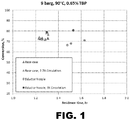
- Ethylene was fed to the top of the reactor at a rate sufficient to maintain a specified pressure of 5-12 bar. Samples of liquid from the reactor were collected and analyzed by gas chromatography.
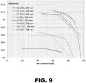
- Figure 1 shows M4 conversion plotted against residence time at two levels of liquid circulation rate to the top of the reactor. Two different nozzles were used to inject the circulated liquid: a jet nozzle (base case) and an eductor. Higher circulation rates resulted in faster reaction kinetics due to both improved gas/liquid and liquid/solid mass transfer characteristics.
- Figure 1 also shows Tet conversion improved with higher residence time (lower M4 feed rate) and higher recirculation rate both in the base case and the eductor case at constant temperature, pressure and TBP concentration.
- the data labeled "base case” had a 1/2" ID liquid nozzle in the top of the reactor headspace directed downward into the liquid.
- Figure 2 shows that the selectivity of the base case and the eductor nozzle case remained above 94% at 80% M4 conversion and higher at lower conversion.
- Example 2 Test Production of 1,1,1,3-Tetrachloropropane in a Batch Autoclave
- the following protocol was designed to test production of 1,1,1,3-tetrachloropropane (250fb) in the lab by reaction of carbon tetrachloride (Tet) and ethylene in the presence of an iron catalyst (metal and/or FeCl 3 ) and an alkyl phosphate promoter in an autoclave with about 10-15 cc liquid volume.
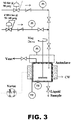
- the experimental set-up is shown in FIG. 3 . Reaction kinetics and selectivity were measured.
- Various test runs were performed in which temperature, iron surface area, FeCl 3 and phosphate addition, ethylene pressure, and/or stirring rate were varied.
- the autoclave was prepared by adding iron wire or chips to the autoclave (the wire can be coiled onto the stirring impeller or coiled in bottom of reactor).
- iron beads or other geometries can be employed to provide the necessary surface area.
- a stock solution of 10% FeCl 3 , 17.5% tributylphosphate (TBP) and 72.5% carbon tetrachloride (Tet) by weight was prepared.
- TBP tributylphosphate
- Tet carbon tetrachloride
- 17 g Tet, 0.126 g tributylphosphate, and 0.765 g stock solution were added to a vial and mixed.
- the liquid reactants were poured into the reactor (autoclave), the reactor was sealed, and stirring was started.
- the autoclave was purged with nitrogen two times and purged with ethylene three times (with stirring to help remove some inerts and trace water from the liquid reactants.) Then, the autoclave was padded with ethylene to about 120 psig, and the ethylene feed was closed. The autoclave was heated to the desired temperature (90-120°C). When the desired temperature was reached, the ethylene feed valve was opened and the pressure was set to the desired level. Samples (0.3 cc) were removed at regular intervals (e.g., 1, 2, 3 hours) and analyzed by GC. When the reaction was complete (or desired Tet conversion achieved), the heat was turned off, the system was cooled to below 35°C, the ethylene was turned off, and the system was vented.
- Table 1 presents the reaction conditions for the test runs. Runs were conducted at 90-120°C, 60-140 psig, and 150-1100 rpm stirring rate. The amounts of iron metal, iron chloride and TBP were varied. Table 2 presents some reaction parameters for the test runs and Table 3 presents the conversion and selectivity data.
- Figure 3 shows the laboratory autoclave apparatus.
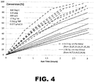
- Figure 4 shows typical trends of Tet conversion versus time for baseline runs at two levels of iron metal surface area.
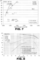
- Figure 5 shows selectivity versus conversion for a similar run set. Higher surface area resulted in higher conversion but slightly lower selectivity.
- Figures 6 and 7 show conversion at 2 hours versus amount of free TBP (amount in molar excess compared to iron chloride added) and total TBP, respectively.
- Figure 6 clearly shows that kinetics are very slow with no iron metal or no added iron chloride. Although iron chloride is required, it can be generated in situ from iron metal, but kinetics will be slow initially.
- Figure 6 shows that, at comparable free TBP levels, high iron chloride addition at the start of a run (high FeCl 3 :free TBP molar ratio) resulted in slower kinetics.
- Comparing Figures 6 and 7 shows that, given some minimum required levels of iron metal and iron chloride, free TBP (not total TBP) is the primary driver of the reaction kinetics. This is especially apparent by comparing the point for Run 3L in Figure 7 at 0.836 g total TBP addition (very high) with the corresponding point in Figure 6 . Though total TBP was high, the high level of Fe-TBP complex inhibited kinetics compared to runs at similar free TBP levels in Figure 6 .
- 3E-1 110 60 300 17.672 0 0.2592 No ethylene 3E-2 110 130 700 17.672 0 0.2592 FeCl3 made in situ 3K 110 120 300 17.829 0.208 0.3649 Hi TBP, v low free 3L 110 120 300 17.741 0.4231 0.8357 Hi free TBP, v high FeCl3 11.49 cm2 metal, Lower FeCl3 and TBP 2R 110 130 300 17.185 0.0237 0.116 Baseline 3 2S 120 130 300 17.211 0.0236 0.1161 vary Temp 2T 100 130 300 17.352 0.0232 0.115 vary Temp 2U 90 130 300 17.246 0.0234 0.1164 vary Temp 2V 95 130 300 17.366 0.0236 0.1161 vary Temp 2W 110 130 700 17.191 0.023 0.1151 vary Temp, Hi stir 2X 100 130 700 17.201 0.0228 0.1139 vary Temp, Hi stir 2Y 120 130 700 17.263 0.0239 0.1168 vary Temp, Hi stir 2Z 120 130 1100 17.275 0.0237 0.1163 vary
- Example 3 Use of a Combination of Fe+2/+3 without Metallic Fe
- Example 4 Generation of Active Species from Metallic Iron and TBP in a Separate Step and Feed to Main Reactor
- Example 5 Continuous Process for the Production of 1,1,1,3-Tetrachloropropane or 1,1,1,3,3-Pentachloropropane
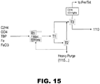
- FIG. 15 presents a simplified diagram of the process for producing 1113.
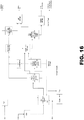
- FIG. 16 presents a more detailed block diagram of the process for producing 1113.
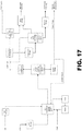
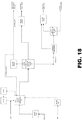
- FIG. 17 and Fig 18 show alternate processes using fewer distillation columns with lower capital cost.
- FIG. 11 A proposed reactor design for the production of 250fb (1,1,1,3-tetrachloropropane or 1113) is shown in Fig. 11 .
- the reactants C 2 H 4 , CCl 4 , and catalyst promoters TEP (Triethylphosphate) or TBP (tributylphosphate) are fed in line 10 into a sparger tube 12.
- the feed sparger tube 12 is connected to center tube 13 inside the reactor chamber 15 with dimension as shown in Table 4.
- the reactants flow upward tube center 13 and leaves the tube into the top of the reactor chamber where the light reactant such as ethylene is collected on top of the gas-phase zone 14.
- the flow may be turbulent or non-turbulent, provided mixing occurs.
- the mixed reactants then flow down into a catalyst Fe(0) zone 21 supported as a fixed bed.
- the porosity of the bed is very high as shown in Table 5 since the Fe(0) can be in the form of wires, structured or unstructured packing.
- Table 5 also shows the potential dimension of the Fe(0) bed 21 as a function of center tube 13 ID.
- the reactants are converted into the products after or during flowing through the bed 21 and exiting the reactor at the annulus region at the bottom of the reactor through the exit line 20 which is driven by the pump 17.
- a portion of the product exiting the pump is taken for purification through line 23 and the rest is recycled back to the reactor via line 22 after cooled or heated by exchanger 18 to maintain the desired temperature as shown in Table 4.
- Table 4 also shows other desired operating condition to produce 30KTA of product shown in Table 6.
- the mass flow of the recycled stream 22 is desirably greater than 3X of the fresh reactant flow in line 10. Table 4.
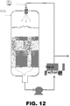
- FIG. 12 presents a diagram of an alternate reactor design that has properties similar to those detailed in Tables 4-6, except that there is no inner tube through the catalyst bed and the liquid circulation stream is returned to the top of the reactor through a nozzle that directs liquid through the gas phase and into the liquid phase of the reactor.
- the nozzle can be a spray nozzle to provide gas/liquid mass transfer, or a jet nozzle that forces gas into and creates turbulence in the liquid phase.
- FIG. 13 Another reactor design is also shown in FIG. 13 .
- This reactor uses a jet educator and an external heat exchanger to control the reaction temperature Tet, TBP, and optionally FeCl 3 are fed into the pump suction, or can be added directly to the reactor.
- the circulation stream from the pump is fed as a motive fluid into the eductor, which is mounted inside the head of the reactor in the gas phase. Gas from the head of the reactor is pulled into the eductor and mixes with the liquid feed to the eductor. The resulting mixture exits the eductor and is directed into the liquid phase inside the reactor.
- An optional extension tube on the exit of the eductor can be used to force the gas phase in the mixture leaving the eductor into the liquid phase in the reactor, thereby creating bubbles.
- Table 7 Table 7.
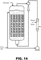
- FIG. 14 Still another reactor design is shown in FIG. 14 .
- This design is similar to that shown in FIG. 13 , except the eductor is mounted outside the reactor and the liquid circulation stream is withdrawn from the liquid phase in the top of the reactor and the eductor exit, containing a gas/liquid mixture, is directed to the bottom of the reactor below the iron catalyst bed.
- Ethylene can be fed to the top of the reactor and Tet, TBP and, optionally, FeCl 3 can be fed into the pump suction.
- FIG. 16 shows a process design that can be used with any of the reactor designs presented above.
- T1 is a flash tower with a condenser and a reboiler for separation of 1113 and 1115.
- the reboiler temperature may be run at 90°C.
- the liquid residence time may be less than 1 day.
- the pressure may be 200 Torr or 4 psia.
- T2 is a catalyst recycle tower with a condenser and a reboiler for heavy purge (i.e., 1115) and catalyst recycle.
- the reboiler temperature may be run at 110°C.
- the liquid residence time may be less than 6 hours at a pressure may be 50 Torr or 1 psia. There may be a 10% purge rate of the heavies stream to incineration.
- T3 is a lights distillation tower with a condenser and a reboiler for separation of Tet and 1113.
- the reboiler temperature may be run at 110°C.
- the liquid residence time may be less than 4 hours at a pressure of 200 Torr or 4 psia.
- Example 5 The continuous process detailed in Example 5 and depicted in Figures 15 and 16 was modified by injecting Tet (a low-boiling liquid) into distillation reboiler of T-2 to facilitate boil-up at lower bottom temperature (to minimize reboiler fouling) and/or higher pressure (to reduce vacuum pump size and energy).
- Tet a low-boiling liquid
- higher pressure to reduce vacuum pump size and energy.
- higher pressure reduced the size of the distillation column and hence potentially reduces the capital cost.
- Table 8 presents results from a standard run and Tet injection runs under two different conditions. Table 8. Process Conditions. Standard Tet Inj - low pressure Tet Inj - high pressure Tet Injection to Reboiler (kg/hr.) 0 1000 1000 Pressure Overhead (mm Hg) 50 50 100 Temperature Overhead (°C) 77.6 16.9 32.4 Temperature Bottom (°C) 93.7 75.4 94.2 Reflux Ratio (Molar) 1 0.35 0.45 Column Diameter (m) 0.827 0.931 0.793 Flow Bottoms (kg/hr.) 194.2 197.7 197.7 1113TCP Bottoms (% Mass) 0.392 0.375 0.371 1115TCPN Overhead (ppm mass) 3 0.5 1 1335TCPN Overhead (ppm mass) 673 668 607
- Example 8 Purification using C 2 H 4 to Improve Purification of 250FB.
- Example 9 Process for Producing 250 FB Comparing Two and Three Distillation Columns.
- Figure 17 presents a process of producing 250FB from the reaction of CCl 4 and C 2 H 4 where two distillation columns are used to purify the product.
- the number of theoretical stages for distillation columns T-2 and T-3 is 17 and it has been kept the same as the case with 3 distillation columns where an additional Column T-1 also uses 17 stages.
- the crude liquid product from reactor R-1 is fed to the first distillation T-2 where the bottom product comprising heavy byproduct is taken from the T-2 bottom stream at 81°C. About 75% of T-2 bottom stream is recycled to R-1 whereas the rest is purged from the process.
- the overhead stream of T-2 at -13°C is compressed and combined with T3 overhead vapor stream (T3OH-V) into a refrigerated condenser at 0.1°C.
- the condensed liquid is fed to the T-3 column where the product with 99.2% purity by mole is obtained in the T-3 bottom stream.
- the T-3 overhead liquid stream consisting mostly CCl 4 is sent to lights liquid storage and sent further to a down-stream process to make Perc.
- the vent stream comprising ethylene from the overhead of C-1 liquid Ring compressor may also be sent to Perc.
- the T-2 bottom heavy stream also includes the TBP-FeClx (where x is 1, 2, or 3) complexes and their compositions are not shown here.
- Table 11 presents two columns that provide 250FB with the same purity as that of three columns and thus this provides a process with lower operating and capital costs.
- Example 10 Process for Preparing 250 FB using One Distillation Column.
- Figure 18 presents the process for producing 250FB using only one distillation column.
- the stream vectors for each stream are provided with the mole fraction of component larger than 10ppm.
- Table 12 compares the purity level of the product using 3 columns vs. 1 column where the product is taken from a side stream from liquid of stage 23 from the top of the distillation column with 30 stages. This shows that about only less than 1% lower purity is achieved with only one column compared to using 3 columns.
- Table 12 presents results from a standard run comparing 3 Columns versus a 1 Column for Purification of the 250FB.
- Example 11 Fe removal by ion exchange
Landscapes
- Chemical & Material Sciences (AREA)
- Organic Chemistry (AREA)
- Chemical Kinetics & Catalysis (AREA)
- Organic Low-Molecular-Weight Compounds And Preparation Thereof (AREA)
- Low-Molecular Organic Synthesis Reactions Using Catalysts (AREA)
Applications Claiming Priority (4)
| Application Number | Priority Date | Filing Date | Title |
|---|---|---|---|
| US201662274601P | 2016-01-04 | 2016-01-04 | |
| US201662277400P | 2016-01-11 | 2016-01-11 | |
| EP17701208.5A EP3400206B1 (de) | 2016-01-04 | 2017-01-04 | Verbesserte verfahren zur zubereitung von halogenierten alkanen |
| PCT/US2017/012223 WO2017120264A1 (en) | 2016-01-04 | 2017-01-04 | Improved processes for preparing halogenated alkanes |
Related Parent Applications (2)
| Application Number | Title | Priority Date | Filing Date |
|---|---|---|---|
| EP17701208.5A Division EP3400206B1 (de) | 2016-01-04 | 2017-01-04 | Verbesserte verfahren zur zubereitung von halogenierten alkanen |
| EP17701208.5A Division-Into EP3400206B1 (de) | 2016-01-04 | 2017-01-04 | Verbesserte verfahren zur zubereitung von halogenierten alkanen |
Publications (2)
| Publication Number | Publication Date |
|---|---|
| EP3770139A1 true EP3770139A1 (de) | 2021-01-27 |
| EP3770139A9 EP3770139A9 (de) | 2023-09-20 |
Family
ID=57868382
Family Applications (2)
| Application Number | Title | Priority Date | Filing Date |
|---|---|---|---|
| EP17701208.5A Active EP3400206B1 (de) | 2016-01-04 | 2017-01-04 | Verbesserte verfahren zur zubereitung von halogenierten alkanen |
| EP20192243.2A Pending EP3770139A1 (de) | 2016-01-04 | 2017-01-04 | Verbesserte verfahren zur zubereitung von halogenierten alkanen |
Family Applications Before (1)
| Application Number | Title | Priority Date | Filing Date |
|---|---|---|---|
| EP17701208.5A Active EP3400206B1 (de) | 2016-01-04 | 2017-01-04 | Verbesserte verfahren zur zubereitung von halogenierten alkanen |
Country Status (6)
| Country | Link |
|---|---|
| US (1) | US10513478B2 (de) |
| EP (2) | EP3400206B1 (de) |
| JP (1) | JP6843866B2 (de) |
| CN (1) | CN108368012B (de) |
| CA (1) | CA3008291A1 (de) |
| WO (1) | WO2017120264A1 (de) |
Families Citing this family (3)
| Publication number | Priority date | Publication date | Assignee | Title |
|---|---|---|---|---|
| JP2021520375A (ja) * | 2018-04-03 | 2021-08-19 | ブルー キューブ アイピー エルエルシー | 吸収体−反応器の組合せを使用してハロゲン化アルカンを生成するための方法 |
| WO2019195251A1 (en) * | 2018-04-03 | 2019-10-10 | Blue Cube Ip Llc | Improved process for preparing a chlorinated alkene by caustic dehydrochlorination of a chlorinated alkane in a jet loop reactor |
| CN111056913A (zh) * | 2019-12-09 | 2020-04-24 | 宁波巨化化工科技有限公司 | 一种1,1,1,3-四氯丙烷的连续生产方法 |
Citations (5)
| Publication number | Priority date | Publication date | Assignee | Title |
|---|---|---|---|---|
| US4650914A (en) | 1983-07-06 | 1987-03-17 | Monsanto Company | Process for producing 1,1,2,3-tetrachloropropene |
| US4885418A (en) * | 1987-09-23 | 1989-12-05 | Bayer Aktiengesellschaft | Process for removing metal halides from liquid organic water-immiscible substances |
| US6313360B1 (en) | 2000-09-29 | 2001-11-06 | Vulcan Materials Company | Process for the manufacture of 1, 1, 1, 3, 3-pentachloropropane |
| WO2012166394A1 (en) * | 2011-05-31 | 2012-12-06 | Dow Global Technologies, Llc | Process for the production of chlorinated propenes |
| US8907147B2 (en) | 2013-02-04 | 2014-12-09 | Honeywell International Inc. | Synthesis of 1,1,2,3-tetrachloropropene |
Family Cites Families (3)
| Publication number | Priority date | Publication date | Assignee | Title |
|---|---|---|---|---|
| JP5309976B2 (ja) * | 2008-12-25 | 2013-10-09 | コベルコ建機株式会社 | 作業機械 |
| JP5741516B2 (ja) * | 2012-04-19 | 2015-07-01 | ダイキン工業株式会社 | フルオロアルキルアイオダイドの製造方法 |
| CN104557401B (zh) * | 2015-01-23 | 2017-03-29 | 浙江大学 | 使用移动床技术增产丙烯和芳烃的方法 |
-
2017
- 2017-01-04 JP JP2018533861A patent/JP6843866B2/ja active Active
- 2017-01-04 EP EP17701208.5A patent/EP3400206B1/de active Active
- 2017-01-04 WO PCT/US2017/012223 patent/WO2017120264A1/en active Application Filing
- 2017-01-04 EP EP20192243.2A patent/EP3770139A1/de active Pending
- 2017-01-04 US US16/067,700 patent/US10513478B2/en active Active
- 2017-01-04 CN CN201780004718.XA patent/CN108368012B/zh active Active
- 2017-01-04 CA CA3008291A patent/CA3008291A1/en not_active Abandoned
Patent Citations (5)
| Publication number | Priority date | Publication date | Assignee | Title |
|---|---|---|---|---|
| US4650914A (en) | 1983-07-06 | 1987-03-17 | Monsanto Company | Process for producing 1,1,2,3-tetrachloropropene |
| US4885418A (en) * | 1987-09-23 | 1989-12-05 | Bayer Aktiengesellschaft | Process for removing metal halides from liquid organic water-immiscible substances |
| US6313360B1 (en) | 2000-09-29 | 2001-11-06 | Vulcan Materials Company | Process for the manufacture of 1, 1, 1, 3, 3-pentachloropropane |
| WO2012166394A1 (en) * | 2011-05-31 | 2012-12-06 | Dow Global Technologies, Llc | Process for the production of chlorinated propenes |
| US8907147B2 (en) | 2013-02-04 | 2014-12-09 | Honeywell International Inc. | Synthesis of 1,1,2,3-tetrachloropropene |
Also Published As
| Publication number | Publication date |
|---|---|
| JP6843866B2 (ja) | 2021-03-17 |
| EP3400206A1 (de) | 2018-11-14 |
| EP3770139A9 (de) | 2023-09-20 |
| US20190023631A1 (en) | 2019-01-24 |
| WO2017120264A1 (en) | 2017-07-13 |
| CA3008291A1 (en) | 2017-07-13 |
| JP2019501914A (ja) | 2019-01-24 |
| CN108368012B (zh) | 2022-08-12 |
| CN108368012A (zh) | 2018-08-03 |
| US10513478B2 (en) | 2019-12-24 |
| EP3400206B1 (de) | 2021-03-24 |
Similar Documents
| Publication | Publication Date | Title |
|---|---|---|
| CN104130100B (zh) | 制备氯化烃的方法 | |
| US8993816B2 (en) | Process to make 1,1,2,3-tetrachloropropene | |
| EP3400206B1 (de) | Verbesserte verfahren zur zubereitung von halogenierten alkanen | |
| CN103429558A (zh) | 联合生产反式-1-氯-3,3,3-三氟丙烯、反式-1,3,3,3-四氟丙烯和1,1,1,3,3-五氟丙烷的集成方法 | |
| CN104981449A (zh) | 用于生产氯化丙烯的方法 | |
| EP3774702B1 (de) | Verbesserte verfahren zur herstellung von halogenierten alkanen | |
| CN112645793A (zh) | 一种生产反式-1-氯-3,3,3-三氟丙烯的工艺系统及方法 | |
| US20110015414A1 (en) | Process for producing glycidol | |
| JPS61145132A (ja) | 1,2‐ジクロルエタンの製法 | |
| JP2019501914A5 (de) | ||
| US11358918B2 (en) | Method for the production of a halogenated alkene by catalyzed dehydrohalogenation of a halogenated alkane | |
| US20210078923A1 (en) | Method for production of a halogenated alkane using an absorber-reactor combination | |
| US20210094897A1 (en) | Improved process for preparing a chlorinated alkene by caustic dehydrochlorination of a chlorinated alkane in a jet loop reactor | |
| JP2001335517A (ja) | 1,1,1,3,3−ペンタクロロプロパンの製造方法 | |
| US20190300458A1 (en) | Methods for preparing chlorinated alkanes by utilizing ferric chloride, an initiator, and an alkylphosphate | |
| JP3213392B2 (ja) | 酢酸の製造法 | |
| CN110627612A (zh) | 一种提高反应过程选择性的管道化生产氟化烷烃方法 | |
| EP0057629B1 (de) | Verfahren zur Herstellung von zweiwertigen Oxalsäureestern in der Gasphase | |
| US20230348345A1 (en) | Processes for preparing pentachloropropane and tetrachloropropene from dichloropropene | |
| US20240018073A1 (en) | Method for treating a heavy byproduct stream from chlorinated propane production | |
| WO2020041731A1 (en) | Gallium catalyzed dehydrochlorination of a chlorinated alkane | |
| JP2012519586A (ja) | 液相反応用の方法及び集成装置 |
Legal Events
| Date | Code | Title | Description |
|---|---|---|---|
| PUAI | Public reference made under article 153(3) epc to a published international application that has entered the european phase |
Free format text: ORIGINAL CODE: 0009012 |
|
| STAA | Information on the status of an ep patent application or granted ep patent |
Free format text: STATUS: THE APPLICATION HAS BEEN PUBLISHED |
|
| AC | Divisional application: reference to earlier application |
Ref document number: 3400206 Country of ref document: EP Kind code of ref document: P |
|
| AK | Designated contracting states |
Kind code of ref document: A1 Designated state(s): AL AT BE BG CH CY CZ DE DK EE ES FI FR GB GR HR HU IE IS IT LI LT LU LV MC MK MT NL NO PL PT RO RS SE SI SK SM TR |
|
| STAA | Information on the status of an ep patent application or granted ep patent |
Free format text: STATUS: REQUEST FOR EXAMINATION WAS MADE |
|
| 17P | Request for examination filed |
Effective date: 20210726 |
|
| RBV | Designated contracting states (corrected) |
Designated state(s): AL AT BE BG CH CY CZ DE DK EE ES FI FR GB GR HR HU IE IS IT LI LT LU LV MC MK MT NL NO PL PT RO RS SE SI SK SM TR |
|
| STAA | Information on the status of an ep patent application or granted ep patent |
Free format text: STATUS: EXAMINATION IS IN PROGRESS |
|
| 17Q | First examination report despatched |
Effective date: 20220408 |