EP3770133A1 - Procédé de modification de cendres volantes - Google Patents
Procédé de modification de cendres volantes Download PDFInfo
- Publication number
- EP3770133A1 EP3770133A1 EP19771265.6A EP19771265A EP3770133A1 EP 3770133 A1 EP3770133 A1 EP 3770133A1 EP 19771265 A EP19771265 A EP 19771265A EP 3770133 A1 EP3770133 A1 EP 3770133A1
- Authority
- EP
- European Patent Office
- Prior art keywords
- fly ash
- cooling
- grains
- classification
- classifying
- Prior art date
- Legal status (The legal status is an assumption and is not a legal conclusion. Google has not performed a legal analysis and makes no representation as to the accuracy of the status listed.)
- Withdrawn
Links
- 239000010881 fly ash Substances 0.000 title claims abstract description 125
- 238000002715 modification method Methods 0.000 title 1
- 238000001816 cooling Methods 0.000 claims abstract description 80
- OKTJSMMVPCPJKN-UHFFFAOYSA-N Carbon Chemical compound [C] OKTJSMMVPCPJKN-UHFFFAOYSA-N 0.000 claims abstract description 57
- 229910052799 carbon Inorganic materials 0.000 claims abstract description 57
- 238000010438 heat treatment Methods 0.000 claims abstract description 51
- 239000000843 powder Substances 0.000 claims abstract description 39
- 238000000034 method Methods 0.000 claims abstract description 26
- 238000002407 reforming Methods 0.000 claims abstract description 17
- 230000007423 decrease Effects 0.000 claims abstract description 12
- 230000003247 decreasing effect Effects 0.000 claims description 18
- 238000003801 milling Methods 0.000 claims description 9
- XLYOFNOQVPJJNP-UHFFFAOYSA-N water Substances O XLYOFNOQVPJJNP-UHFFFAOYSA-N 0.000 claims description 5
- 239000007789 gas Substances 0.000 description 33
- 238000002156 mixing Methods 0.000 description 12
- 230000001174 ascending effect Effects 0.000 description 10
- 239000004568 cement Substances 0.000 description 9
- 239000002994 raw material Substances 0.000 description 7
- 239000006185 dispersion Substances 0.000 description 6
- 239000003245 coal Substances 0.000 description 5
- QVGXLLKOCUKJST-UHFFFAOYSA-N atomic oxygen Chemical compound [O] QVGXLLKOCUKJST-UHFFFAOYSA-N 0.000 description 3
- 229910052760 oxygen Inorganic materials 0.000 description 3
- 239000001301 oxygen Substances 0.000 description 3
- 239000000126 substance Substances 0.000 description 3
- 230000015572 biosynthetic process Effects 0.000 description 2
- 238000006243 chemical reaction Methods 0.000 description 2
- 239000000498 cooling water Substances 0.000 description 2
- 239000000446 fuel Substances 0.000 description 2
- 239000008187 granular material Substances 0.000 description 2
- RBTBFTRPCNLSDE-UHFFFAOYSA-N 3,7-bis(dimethylamino)phenothiazin-5-ium Chemical compound C1=CC(N(C)C)=CC2=[S+]C3=CC(N(C)C)=CC=C3N=C21 RBTBFTRPCNLSDE-UHFFFAOYSA-N 0.000 description 1
- 239000003795 chemical substances by application Substances 0.000 description 1
- 238000002485 combustion reaction Methods 0.000 description 1
- 238000009833 condensation Methods 0.000 description 1
- 230000005494 condensation Effects 0.000 description 1
- 230000001186 cumulative effect Effects 0.000 description 1
- 239000000428 dust Substances 0.000 description 1
- 230000000694 effects Effects 0.000 description 1
- 238000010304 firing Methods 0.000 description 1
- 238000004519 manufacturing process Methods 0.000 description 1
- 239000000463 material Substances 0.000 description 1
- 229960000907 methylthioninium chloride Drugs 0.000 description 1
- 239000000203 mixture Substances 0.000 description 1
- 239000004570 mortar (masonry) Substances 0.000 description 1
- 238000005086 pumping Methods 0.000 description 1
- 238000005245 sintering Methods 0.000 description 1
- 238000001179 sorption measurement Methods 0.000 description 1
- 239000007921 spray Substances 0.000 description 1
- 239000002699 waste material Substances 0.000 description 1
Images

Classifications
-
- B—PERFORMING OPERATIONS; TRANSPORTING
- B07—SEPARATING SOLIDS FROM SOLIDS; SORTING
- B07B—SEPARATING SOLIDS FROM SOLIDS BY SIEVING, SCREENING, SIFTING OR BY USING GAS CURRENTS; SEPARATING BY OTHER DRY METHODS APPLICABLE TO BULK MATERIAL, e.g. LOOSE ARTICLES FIT TO BE HANDLED LIKE BULK MATERIAL
- B07B4/00—Separating solids from solids by subjecting their mixture to gas currents
- B07B4/08—Separating solids from solids by subjecting their mixture to gas currents while the mixtures are supported by sieves, screens, or like mechanical elements
-
- B—PERFORMING OPERATIONS; TRANSPORTING
- B09—DISPOSAL OF SOLID WASTE; RECLAMATION OF CONTAMINATED SOIL
- B09B—DISPOSAL OF SOLID WASTE NOT OTHERWISE PROVIDED FOR
- B09B3/00—Destroying solid waste or transforming solid waste into something useful or harmless
- B09B3/40—Destroying solid waste or transforming solid waste into something useful or harmless involving thermal treatment, e.g. evaporation
-
- C—CHEMISTRY; METALLURGY
- C04—CEMENTS; CONCRETE; ARTIFICIAL STONE; CERAMICS; REFRACTORIES
- C04B—LIME, MAGNESIA; SLAG; CEMENTS; COMPOSITIONS THEREOF, e.g. MORTARS, CONCRETE OR LIKE BUILDING MATERIALS; ARTIFICIAL STONE; CERAMICS; REFRACTORIES; TREATMENT OF NATURAL STONE
- C04B18/00—Use of agglomerated or waste materials or refuse as fillers for mortars, concrete or artificial stone; Treatment of agglomerated or waste materials or refuse, specially adapted to enhance their filling properties in mortars, concrete or artificial stone
- C04B18/04—Waste materials; Refuse
- C04B18/06—Combustion residues, e.g. purification products of smoke, fumes or exhaust gases
- C04B18/08—Flue dust, i.e. fly ash
-
- B—PERFORMING OPERATIONS; TRANSPORTING
- B02—CRUSHING, PULVERISING, OR DISINTEGRATING; PREPARATORY TREATMENT OF GRAIN FOR MILLING
- B02C—CRUSHING, PULVERISING, OR DISINTEGRATING IN GENERAL; MILLING GRAIN
- B02C18/00—Disintegrating by knives or other cutting or tearing members which chop material into fragments
- B02C18/0084—Disintegrating by knives or other cutting or tearing members which chop material into fragments specially adapted for disintegrating garbage, waste or sewage
-
- B—PERFORMING OPERATIONS; TRANSPORTING
- B03—SEPARATION OF SOLID MATERIALS USING LIQUIDS OR USING PNEUMATIC TABLES OR JIGS; MAGNETIC OR ELECTROSTATIC SEPARATION OF SOLID MATERIALS FROM SOLID MATERIALS OR FLUIDS; SEPARATION BY HIGH-VOLTAGE ELECTRIC FIELDS
- B03B—SEPARATING SOLID MATERIALS USING LIQUIDS OR USING PNEUMATIC TABLES OR JIGS
- B03B9/00—General arrangement of separating plant, e.g. flow sheets
- B03B9/04—General arrangement of separating plant, e.g. flow sheets specially adapted for furnace residues, smeltings, or foundry slags
-
- B—PERFORMING OPERATIONS; TRANSPORTING
- B07—SEPARATING SOLIDS FROM SOLIDS; SORTING
- B07B—SEPARATING SOLIDS FROM SOLIDS BY SIEVING, SCREENING, SIFTING OR BY USING GAS CURRENTS; SEPARATING BY OTHER DRY METHODS APPLICABLE TO BULK MATERIAL, e.g. LOOSE ARTICLES FIT TO BE HANDLED LIKE BULK MATERIAL
- B07B11/00—Arrangement of accessories in apparatus for separating solids from solids using gas currents
- B07B11/02—Arrangement of air or material conditioning accessories
-
- B—PERFORMING OPERATIONS; TRANSPORTING
- B07—SEPARATING SOLIDS FROM SOLIDS; SORTING
- B07B—SEPARATING SOLIDS FROM SOLIDS BY SIEVING, SCREENING, SIFTING OR BY USING GAS CURRENTS; SEPARATING BY OTHER DRY METHODS APPLICABLE TO BULK MATERIAL, e.g. LOOSE ARTICLES FIT TO BE HANDLED LIKE BULK MATERIAL
- B07B11/00—Arrangement of accessories in apparatus for separating solids from solids using gas currents
- B07B11/06—Feeding or discharging arrangements
-
- B—PERFORMING OPERATIONS; TRANSPORTING
- B07—SEPARATING SOLIDS FROM SOLIDS; SORTING
- B07B—SEPARATING SOLIDS FROM SOLIDS BY SIEVING, SCREENING, SIFTING OR BY USING GAS CURRENTS; SEPARATING BY OTHER DRY METHODS APPLICABLE TO BULK MATERIAL, e.g. LOOSE ARTICLES FIT TO BE HANDLED LIKE BULK MATERIAL
- B07B4/00—Separating solids from solids by subjecting their mixture to gas currents
- B07B4/02—Separating solids from solids by subjecting their mixture to gas currents while the mixtures fall
- B07B4/025—Separating solids from solids by subjecting their mixture to gas currents while the mixtures fall the material being slingered or fled out horizontally before falling, e.g. by dispersing elements
-
- B—PERFORMING OPERATIONS; TRANSPORTING
- B07—SEPARATING SOLIDS FROM SOLIDS; SORTING
- B07B—SEPARATING SOLIDS FROM SOLIDS BY SIEVING, SCREENING, SIFTING OR BY USING GAS CURRENTS; SEPARATING BY OTHER DRY METHODS APPLICABLE TO BULK MATERIAL, e.g. LOOSE ARTICLES FIT TO BE HANDLED LIKE BULK MATERIAL
- B07B9/00—Combinations of apparatus for screening or sifting or for separating solids from solids using gas currents; General arrangement of plant, e.g. flow sheets
- B07B9/02—Combinations of similar or different apparatus for separating solids from solids using gas currents
-
- C—CHEMISTRY; METALLURGY
- C04—CEMENTS; CONCRETE; ARTIFICIAL STONE; CERAMICS; REFRACTORIES
- C04B—LIME, MAGNESIA; SLAG; CEMENTS; COMPOSITIONS THEREOF, e.g. MORTARS, CONCRETE OR LIKE BUILDING MATERIALS; ARTIFICIAL STONE; CERAMICS; REFRACTORIES; TREATMENT OF NATURAL STONE
- C04B7/00—Hydraulic cements
- C04B7/24—Cements from oil shales, residues or waste other than slag
- C04B7/26—Cements from oil shales, residues or waste other than slag from raw materials containing flue dust, i.e. fly ash
-
- C—CHEMISTRY; METALLURGY
- C04—CEMENTS; CONCRETE; ARTIFICIAL STONE; CERAMICS; REFRACTORIES
- C04B—LIME, MAGNESIA; SLAG; CEMENTS; COMPOSITIONS THEREOF, e.g. MORTARS, CONCRETE OR LIKE BUILDING MATERIALS; ARTIFICIAL STONE; CERAMICS; REFRACTORIES; TREATMENT OF NATURAL STONE
- C04B7/00—Hydraulic cements
- C04B7/36—Manufacture of hydraulic cements in general
- C04B7/38—Preparing or treating the raw materials individually or as batches, e.g. mixing with fuel
- C04B7/40—Dehydrating; Forming, e.g. granulating
-
- B—PERFORMING OPERATIONS; TRANSPORTING
- B02—CRUSHING, PULVERISING, OR DISINTEGRATING; PREPARATORY TREATMENT OF GRAIN FOR MILLING
- B02C—CRUSHING, PULVERISING, OR DISINTEGRATING IN GENERAL; MILLING GRAIN
- B02C2201/00—Codes relating to disintegrating devices adapted for specific materials
- B02C2201/06—Codes relating to disintegrating devices adapted for specific materials for garbage, waste or sewage
-
- B—PERFORMING OPERATIONS; TRANSPORTING
- B07—SEPARATING SOLIDS FROM SOLIDS; SORTING
- B07B—SEPARATING SOLIDS FROM SOLIDS BY SIEVING, SCREENING, SIFTING OR BY USING GAS CURRENTS; SEPARATING BY OTHER DRY METHODS APPLICABLE TO BULK MATERIAL, e.g. LOOSE ARTICLES FIT TO BE HANDLED LIKE BULK MATERIAL
- B07B2230/00—Specific aspects relating to the whole B07B subclass
- B07B2230/01—Wet separation
-
- B—PERFORMING OPERATIONS; TRANSPORTING
- B09—DISPOSAL OF SOLID WASTE; RECLAMATION OF CONTAMINATED SOIL
- B09B—DISPOSAL OF SOLID WASTE NOT OTHERWISE PROVIDED FOR
- B09B2101/00—Type of solid waste
- B09B2101/30—Incineration ashes
-
- C—CHEMISTRY; METALLURGY
- C04—CEMENTS; CONCRETE; ARTIFICIAL STONE; CERAMICS; REFRACTORIES
- C04B—LIME, MAGNESIA; SLAG; CEMENTS; COMPOSITIONS THEREOF, e.g. MORTARS, CONCRETE OR LIKE BUILDING MATERIALS; ARTIFICIAL STONE; CERAMICS; REFRACTORIES; TREATMENT OF NATURAL STONE
- C04B2111/00—Mortars, concrete or artificial stone or mixtures to prepare them, characterised by specific function, property or use
- C04B2111/10—Compositions or ingredients thereof characterised by the absence or the very low content of a specific material
- C04B2111/1087—Carbon free or very low carbon content fly ashes; Fly ashes treated to reduce their carbon content or the effect thereof
-
- Y—GENERAL TAGGING OF NEW TECHNOLOGICAL DEVELOPMENTS; GENERAL TAGGING OF CROSS-SECTIONAL TECHNOLOGIES SPANNING OVER SEVERAL SECTIONS OF THE IPC; TECHNICAL SUBJECTS COVERED BY FORMER USPC CROSS-REFERENCE ART COLLECTIONS [XRACs] AND DIGESTS
- Y02—TECHNOLOGIES OR APPLICATIONS FOR MITIGATION OR ADAPTATION AGAINST CLIMATE CHANGE
- Y02W—CLIMATE CHANGE MITIGATION TECHNOLOGIES RELATED TO WASTEWATER TREATMENT OR WASTE MANAGEMENT
- Y02W30/00—Technologies for solid waste management
- Y02W30/20—Waste processing or separation
-
- Y—GENERAL TAGGING OF NEW TECHNOLOGICAL DEVELOPMENTS; GENERAL TAGGING OF CROSS-SECTIONAL TECHNOLOGIES SPANNING OVER SEVERAL SECTIONS OF THE IPC; TECHNICAL SUBJECTS COVERED BY FORMER USPC CROSS-REFERENCE ART COLLECTIONS [XRACs] AND DIGESTS
- Y02—TECHNOLOGIES OR APPLICATIONS FOR MITIGATION OR ADAPTATION AGAINST CLIMATE CHANGE
- Y02W—CLIMATE CHANGE MITIGATION TECHNOLOGIES RELATED TO WASTEWATER TREATMENT OR WASTE MANAGEMENT
- Y02W30/00—Technologies for solid waste management
- Y02W30/50—Reuse, recycling or recovery technologies
- Y02W30/52—Mechanical processing of waste for the recovery of materials, e.g. crushing, shredding, separation or disassembly
-
- Y—GENERAL TAGGING OF NEW TECHNOLOGICAL DEVELOPMENTS; GENERAL TAGGING OF CROSS-SECTIONAL TECHNOLOGIES SPANNING OVER SEVERAL SECTIONS OF THE IPC; TECHNICAL SUBJECTS COVERED BY FORMER USPC CROSS-REFERENCE ART COLLECTIONS [XRACs] AND DIGESTS
- Y02—TECHNOLOGIES OR APPLICATIONS FOR MITIGATION OR ADAPTATION AGAINST CLIMATE CHANGE
- Y02W—CLIMATE CHANGE MITIGATION TECHNOLOGIES RELATED TO WASTEWATER TREATMENT OR WASTE MANAGEMENT
- Y02W30/00—Technologies for solid waste management
- Y02W30/50—Reuse, recycling or recovery technologies
- Y02W30/91—Use of waste materials as fillers for mortars or concrete
Definitions
- This invention relates to a process for reforming the fly ash.
- fly ash When the fly ash is used as an admixture with the cement or the concrete, it is, usually, desired that the content of the unburned carbon in the fly ash is better small.
- the fly ash generated from the coal burning thermal power plants contains the unburned carbon in various amounts, say, about 15% by mass at the greatest. Therefore, only some of the fly ash can be used as the admixture.
- the fly ash must be heated at a temperature of not lower than 700°C. This is because at temperatures lower than 700°C, very extended periods of time are necessary for removing the unburned carbon.
- the amount of the unburned carbon can be greatly decreased in short periods of time if the temperature for heating is elevated. As the temperature becomes high, however, the fly ash grains tend to melt-adhere together and turn into lumps. The higher the temperature, therefore, the larger the ratio of forming lumps. Besides, extended periods of time become necessary for cooling the lumps.
- the temperature for heating should be set to be not higher than 780°C. To remove the unburned carbon, therefore, the temperature of heating should best be in a range of 700 to 780°C. It is, however, very difficult to conduct the heating maintaining the temperature in such a limited range.
- Patent Documents
- an object of the present invention to provide a process for reforming the fly ash that contains the unburned carbon in varying amounts by reliably decreasing the amount of the unburned carbon in short periods of time to such a degree that the fly ash after reformed can all be used as an admixture through a relatively simple process.
- the present inventors have keenly forwarded the study.
- the inventors have discovered the fact that the fly ash even containing lumps can be efficiently cooled if it is subjected to the wind power classification so as to be also cooled by the wind, that the improved fly ash can be thus obtained having properties suited for being used as an admixture, and have completed the present invention.
- a process for reforming the fly ash including:
- the temperature for heating has been set to lie over a range which is so high and wide as from 780 to 1000°C. Therefore, even the raw fly ash powders containing the unburned carbon in different amounts can be heat-treated, in relatively short periods of time, continuously and maintaining stability, into a reformed fly ash that can be favorably used as an admixture with the cement or the concrete.
- the fly ash is heated at a high temperature.
- the fly ash is heated in the heating apparatus and contains the carbon in a decreased amount; i.e., the heat-treated fly ash assumes the form of lumps containing massive grains of large grain sizes.
- the heat-treated fly ash is introduced in a state of being maintained at a high temperature into a cooling/classifying apparatus where it is subjected to the cooling and, at the same time, to the wind power classification by using the gas flow for cooling and classification, and is then separated into a coarse grains containing large massive grains and a fine grains.
- the gas flow e.g., air
- the heat-treated fly ash whereby the fine grains that can be easily cooled is lifted up and is discharged out of the apparatus while the coarse grains that cannot be easily cooled is allowed to stay in the apparatus. That is, the fine grains that can be easily cooled is quickly discharged out of the apparatus while coming in contact with the gas flow for cooling and classification whereas the coarse grains that cannot be easily cooled is allowed to stay in the apparatus and is maintained in a state of being contacted to the gas flow for cooling and classification at all times. Therefore, the coarse grains can be efficiently cooled in short periods of time. That is, in the form of large lumps without being classified, the fly ash can be cooled only poorly efficiently requiring very extended periods of time.
- the gas flow e.g., air
- the heat-treated fly ash containing the unburned carbon in decreased amounts is recovered being classified into the fine grains and the milled product of coarse granules.
- the fly ash that contains the unburned carbon in decreased amounts after having been heat-treated can all be efficiently used as an admixture with the cement or the concrete.
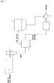
- a raw fly ash powder containing the unburned carbon is heated in a heating apparatus 1 (heating step) to decrease the amount of the unburned carbon.
- the heat-treated fly ash containing the unburned carbon in a decreased amount is introduced in a state of being maintained at a high temperature into a cooling/classifying apparatus 3 and is cooled and classified (cooling/classifying step).
- a fine grains obtained through the cooling and classification is recovered by a dust-collecting apparatus 5 (fine powder-recovering step) while a coarse grains obtained through the cooling and classification is introduced into a milling apparatus 7 (milling step) where it is milled down to a predetermined grain size and is then recovered.
- the thus recovered fine grains and milled product can be used in their own forms .
- the two are mixed together in a mixing apparatus 9, and the mixture thereof is shipped as a product for forming an admixture with the cement or the concrete.
- the raw fly ash powder that is to be put to the reforming treatment is a fly ash that usually generates in the facilities that burn the coal, such as coal burning thermal power plants.
- the raw fly ash powder may also be a fly ash that generates after having burned the coal, or after having burned the fuel other than the coal or any fuel burned together with any inflammable wastes.
- the grains contained in the raw fly ash powder have a maximum diameter which is, usually, not larger than 150 ⁇ m but not smaller than 100 ⁇ m.
- the raw fly ash powder usually contains the unburned carbon in an amount of about 1 to about 15% by mass.
- the unburned carbon that is contained in large amounts causes a problem when the fly ash is used as an admixture with the cement or the concrete (hereinafter often called simply as mixed material).
- the unburned carbon when contained in large amounts, float on the surfaces of the mortar or the concrete and may form darkened portions.
- chemicals such as chemical blending agents mixed into the fly ash may be adsorbed by the unburned carbon, and may lose their functions.
- the present invention is applied to reforming, specifically, the fly ash that contains the unburned carbon in amounts in excess of 3% by mass and, particularly, the fly ash that contains the unburned carbon in amounts in excess of 5% by mass.
- the raw fly ash powder is introduced into the heating apparatus 1 where it is heated to burn the unburned carbon and to thereby decrease the amount of the unburned carbon.
- the heating is executed so that the amount of the unburned carbon after heated is, for example, not more than 3% by mass, preferably, not more than 1% by mass and, specifically, not more than 0.1% by mass.
- the raw fly ash powder to be introduced into the heating apparatus 1 and the fly ash (reformed fly ash) heated in the heating apparatus 1 and coming out from the outlet port, are suitably sampled and measured for their amounts of the unburned carbon.
- the temperature for heating and the time for heating are then set based on the measured values.
- the temperature for heating in the heating apparatus 1 is set to lie in a range of 780 to 1000°C and, preferably, 800 to 950°C. Since the heating is executed in such a high and wide temperature range, the fly ash can be continuously heated maintaining stability even in case the amount of the unburned carbon frequently varies in the fly ash that is introduced into the heating apparatus 1.
- the fly ash grains melt-adhere together to form very large lumps that may cause such inconveniences as clogging in the pipes and melt-adhesion on the wall surfaces of the heating apparatus 1. Besides, the fly ash undergoes a change in its chemical properties and often cannot be used as the admixture.
- the raw fly ash powder is heated in the high-temperature range as described above, and hence the fly ash grains melt-adhere together inevitably forming large massive grains simultaneously with the formation of the fine powder, the massive grains having maximum diameters of, for example, not smaller than 150 ⁇ m.
- the fly ash before being heated contains the grains having maximum diameters of not larger than 150 ⁇ m, and from which it can be confirmed that the massive grains are formed due to the heating. That is, the higher the temperature for heating or the longer the time for heating, the more the fly ash powder turns into lumps, and larger massive grains are formed much.
- the present invention therefore, necessitates the cooling and classification as will be described later.
- the temperature and the time for heating are so set that the amount of massive grains having maximum diameters of not smaller than 150 ⁇ m does not exceed 50% by mass and, specifically, does not exceed 30% by mass under a condition that the amount of the unburned carbon is decreased down to lie in the above-mentioned range.
- a generally employed heating furnace can be used as the heating apparatus 1 for executing the heating as described above.
- a rotary kiln there is desirably used a rotary kiln, a roller hearth kiln, a tunnel kiln, a fluidized bed furnace or a swirl flow type firing furnace.
- An externally heated type rotary kiln is most desirably used since it makes it easy to control the temperature to lie over a range of 780°C to 1000°C and, therefore, to execute the treatment continuously and in large amounts.
- use of the rotary kiln may permit the fly ash powder to turn into lumps more easily than when any other heating systems are used, the process of the present invention can be highly effectively applied to solving this problem.
- the fly ash containing the unburned carbon in a decreased amount as a result of the heating is introduced in the state of being heated at a high temperature into the cooling/classifying apparatus 3. That is, the heat-treated fly ash in the form of lumps containing fine powder is introduced from the heating apparatus 1 into the cooling/classifying apparatus 3 in the state of being heated at a high temperature though it may be naturally cooled to some extent through the pipe, and is classified into the fine powder and the coarse granular powder. That is, the temperature of the heat-treated fly ash while being conveyed has not been maintained constant.
- the temperature may drop by about several tens of degrees centigrade to about three hundreds of degrees centigrade while it is being conveyed through the pipe to arrive at the cooling/classifying apparatus 3.
- the heat-treated fly ash is still maintained at a temperature of as high as at least not lower than 300°C.
- the fly ash is separated in the cooling/classifying apparatus 3 into the fine powder contained in the lumps and the coarse granular powder (including massive grains of large grain sizes) .
- the fine powder and the coarse granular powder are cooled.
- the heat-treated fly ash contains the coarse granular powder that cannot be easily cooled down as will be described later.
- the heat-treated fly ash is conveyed at such an efficiency that the temperature thereof is preferably not lower than 400°C, more preferably, not lower than 500°C and, particularly preferably, not lower than 550°C at a moment when it is introduced into the cooling/classifying apparatus 3.
- the heat-treated fly ash discharged from the heating apparatus 1 contains the fine powder having a large specific surface area as well as the massive granular powder having a small specific surface area.
- the fly ash is separated into the coarse powder containing much massive granules that can be cooled poorly efficiently and the fine powder that has a large specific surface area and can be efficiently cooled. The coarse powder is then positively cooled down to improve the cooling efficiency.
- the cooling/classifying apparatus 3 carries out the classification based on the wind power classification, and has such a structure that carries out the cooling based on the gas flow used for the classification.
- FIG. 2 schematically illustrates the structure of the cooling/classifying apparatus 3.
- the apparatus 3 is a hollow cylindrical body with its bottom wall being a tilted wall expanding from the lower side toward the upper side.
- the tilted wall is continuous to a straight drum portion which is then continuous to a top wall on the upper side.
- the top wall is forming a tilted wall that contracts in diameter upward.
- the bottom wall forms a gas flow introduction port 11 for introducing the gas flow for cooling
- the straight drum portion is provided, at its upper portion, with a raw material throw port 13
- the top wall forms a fine grains take-out port 15 that also works as a gas flow discharge port.
- the drum portion is, further, provided with a coarse grains take-out port 17.
- the inner space of the hollow cylindrical body is partitioned by a dispersion plate 19 near the boundary between the drum portion and the bottom wall.
- the upper wall is provided with a water-sprinkling nozzle 21.
- a gas (usually, the air) for cooling and classification is introduced through the gas flow introduction port 11 and, as shown in Fig. 2 , the gas for cooling forms an ascending gas flow Z in the apparatus 3.
- the dispersion plate 19 is forming a number of small holes being uniformly distributed, and the ascending gas flow Z is introduced through the dispersion plate 19 without being deflected.
- the above-mentioned heat-treated fly ash has been maintained at a high temperature of not lower than, for example, 480°C.
- the heat-treated fly ash of such a high temperature is thrown into the raw material throw port 13, comes into contact with the ascending gas flow Z that has passed through the dispersion plate 19, and is cooled and classified.
- the fine grains which is light in weight rides on the ascending gas stream Z and is discharged from the discharge port 15 while being cooled.
- the coarse grains of heavy weight deposits on the dispersion plate 19 and stays in the apparatus 3. After having reached a predetermined amount, the heavy coarse grains starts overflowing and is discharged from the coarse grains take-out port 17.
- the fine grains that can be easily cooled is discharged out of the apparatus 3 accompanying the ascending gas flow Z while being cooled by the ascending gas flow Z, whereas the coarse grains that cannot be easily cooled is separated from the fine grains, stays in the apparatus 3, and is cooled being exposed to the ascending gas flow Z at all times. Therefore, the cooling can be accomplished efficiently and in short periods of time.
- the cooling apparatus of the mechanically conveying type for example, if it is attempted to cool the fine grains and the coarse grains in a state of being mixed together, then it becomes necessary to employ the condition that suits for the coarse grains that cannot be easily cooled.
- the fine grains having a small size moves toward the upper side in the apparatus and is discharged out of the apparatus 3 in relatively short periods of time, whereas the coarse grains having a large size moves toward the lower side in the apparatus 3 and is discharged from the apparatus after having stayed therein for relatively long periods of time. It is, therefore, made possible to easily secure the times necessary for cooling the fine grains and the coarse grains, and hence to efficiently execute the cooling.
- the cooling apparatus of the mechanically conveying type in many cases, employs the indirect cooling system causing, therefore, a decrease in the cooling efficiency, an increase in the heat-conducting areas and, therefore, an increase in the size of the apparatus.
- the cooling/classifying apparatus 3 used in the present invention employs the direct cooling system featuring a high cooling efficiency, introducing the gas flow Z uniformly into the apparatus to fluidize the grains, offering increased contact areas between the grains and the gas, and hence making it possible to decrease the size of the apparatus.
- the apparatus 3 executes the cooling and the classification simultaneously, and helps simplify the steps for reforming the fly ash.
- the fine grains and the coarse grains are, respectively, cooled down to not higher than 200°C and, specifically, not higher than 100°C since it obviates the need of constructing the apparatuses in the subsequent steps in a heat-resistant structure.
- the gas for cooling the heat-treated fly ash that is thrown into the cooling/classifying apparatus 3 there can be, usually, used the air. Namely, the air is blown through the gas flow introduction port 11 to form the ascending gas flow Z.
- the gas may have normal temperature and needs not be cooled by using a special cooling apparatus; i.e., the gas is directly used to form the ascending gas flow Z and thereby to cool the fine grains and the coarse grains down to the above-mentioned temperature.
- the cooling water may be sprayed from the sprinkling nozzle 21 provided at an upper part of the apparatus 3 to shorten the cooling time.
- the temperature in the apparatus 3 is controlled to such a degree that causes no condensation.
- the water can be sprinkled in an amount of about one liter to about 100 liters per ton of the fly ash.
- the temperature of the recovered fly ash can be lowered down to not higher than 200°C, preferably, not higher than 150°C and, particularly preferably, not higher than 100°C.
- the classification point In conducting the classification (i.e., wind power classification) by utilizing the ascending gas flow Z, further, the classification point varies depending on the flow rate and the flow speed of the gas.
- the classification point increases with an increase in the flow rate or in the flow speed, making it possible to discharge grains of large grain sizes.
- the classification point can be thus set.
- the JIS Standard specifies, for example, a 45 ⁇ m sieve residue of the fly ash. It is, therefore, desired to set the classification point relying on the 45 ⁇ m sieve residue. Concretely speaking, it is desired that the classification point is so set that the 45 ⁇ m sieve residue of the fine grains is not more than 34% by mass and, preferably, not more than 20% by mass.
- the most generally used JIS Type II Standard specifies the 45 ⁇ m sieve residue to be not more than 40% by mass. In the present invention, however, this value is specified to be not more than 34% by mass.
- the classification point is so set that the fine grains obtained through the classification has a median diameter D 50 of not more than 30 ⁇ m and, preferably, not more than 20 ⁇ m calculated as the volume.
- the cumulative volume 50% diameter D 50 (median diameter) of the fly ash used as the admixture is 10 to 40 ⁇ m, and it is also possible to attain a median diameter equivalent thereto.
- the ratio of recovering the fine grains and the coarse grains may vary depending on the degree of sintering the heat-treated fly ash grains that are thrown in. Usually, however, the coarse grains is recovered at a ratio of not more than 50% by mass.
- the above-mentioned median diameter Dso is measured by using, for example, a laser diffraction grain size distribution meter.
- the fine fly ash powder is separated and cooled by being classified in the cooling/classifying apparatus 3.
- the fine fly ash powder is a reformed fly ash containing the unburned carbon in a decreased amount as a result of the heat treatment, and is recovered by the dust-collecting apparatus 5.
- the dust-collecting apparatus 5 for recovering the fine grains there can be used any apparatus without any problem, such as an electric dust collector, a bag filter or a cyclone that has been used industrially.
- the fine grains recovered by the dust-collecting apparatus 5 can be used in its form as an admixture.
- the coarse grains taken out from the cooling/classifying apparatus 3 as a result of having overflown from the apparatus 3 can also be used in its form as a raw material for the production of cement clinkers.
- the coarse granular grains must be milled. This is because the coarse granular grains has very large grain sizes containing in many cases very large massive grains in sizes of from several centimeters to several tens of centimeters or larger.
- the coarse grains is milled down to a 45 ⁇ m sieve residue of not more than 34% by mass and, specifically, not more than 20% by mass.
- the coarse grains after milled has a median diameter D 50 of not more than 30 ⁇ m and, specifically, not more than 20 ⁇ m.
- the milling apparatus there is no specific limitation on the milling apparatus, and there can be used a tube mill, a vibration mill, a roller mill, a roll crasher or a hamper crasher that has been industrially employed.
- Either the fine grains recovered from the dust-collecting apparatus 5 or the milled product of the coarse grains recovered from the milling apparatus can serve as a reformed fly ash and can be used in their forms as an admixture with the cement or the concrete. From the standpoint of obtaining the reformed fly ash having uniform quality and containing the unburned carbon in a greatly decreased amount, however, it is desired that the above two grains are introduced into the mixing apparatus 9 and are mixed together.
- the mixing apparatus 9 there is no specific limitation on the mixing apparatus 9, and there can be used a mixing apparatus that has usually been used for mixing the grains together. For instance, there can be used a stirrer type mixing machine or a jet stream mixing machine that use the compressed air.
- the grains can also be mixed together in a blending silo, in a continuous grains conveying machine or in a pneumatic pumping equipment.
- the thus obtained reformed fly ash contains the unburned carbon in a decreased amount, has its grain size suitably adjusted, and can be used as an admixture with the cement or as an admixture with the concrete in a customary manner.
Landscapes
- Engineering & Computer Science (AREA)
- Chemical & Material Sciences (AREA)
- Ceramic Engineering (AREA)
- Environmental & Geological Engineering (AREA)
- Materials Engineering (AREA)
- Structural Engineering (AREA)
- Organic Chemistry (AREA)
- Civil Engineering (AREA)
- Combustion & Propulsion (AREA)
- Mechanical Engineering (AREA)
- Physics & Mathematics (AREA)
- Thermal Sciences (AREA)
- Food Science & Technology (AREA)
- Processing Of Solid Wastes (AREA)
Applications Claiming Priority (2)
| Application Number | Priority Date | Filing Date | Title |
|---|---|---|---|
| JP2018050837 | 2018-03-19 | ||
| PCT/JP2019/009767 WO2019181619A1 (fr) | 2018-03-19 | 2019-03-11 | Procédé de modification de cendres volantes |
Publications (1)
| Publication Number | Publication Date |
|---|---|
| EP3770133A1 true EP3770133A1 (fr) | 2021-01-27 |
Family
ID=67987757
Family Applications (1)
| Application Number | Title | Priority Date | Filing Date |
|---|---|---|---|
| EP19771265.6A Withdrawn EP3770133A1 (fr) | 2018-03-19 | 2019-03-11 | Procédé de modification de cendres volantes |
Country Status (7)
| Country | Link |
|---|---|
| US (1) | US20210032163A1 (fr) |
| EP (1) | EP3770133A1 (fr) |
| JP (1) | JP7183251B2 (fr) |
| KR (1) | KR20200130313A (fr) |
| CN (1) | CN111971259A (fr) |
| CA (1) | CA3093644A1 (fr) |
| WO (1) | WO2019181619A1 (fr) |
Families Citing this family (5)
| Publication number | Priority date | Publication date | Assignee | Title |
|---|---|---|---|---|
| EP3766854A4 (fr) * | 2018-03-13 | 2021-12-15 | Tokuyama Corporation | Procédé et dispositif de modification de cendres volantes |
| KR20220046964A (ko) | 2020-10-08 | 2022-04-15 | 삼성전자주식회사 | 멀티 챗봇을 이용하여 질의에 응답하는 전자 장치 및 그 제어 방법 |
| FR3119335B1 (fr) * | 2021-01-29 | 2023-03-17 | Fives Fcb | Procédé et installation de traitement de cendres volantes |
| CN113333436B (zh) * | 2021-05-21 | 2022-04-08 | 中国矿业大学 | 一种煤气化细渣的全组分综合利用方法 |
| CN115069550A (zh) * | 2022-06-17 | 2022-09-20 | 盐津津玺商贸有限责任公司 | 一种干粉砂粒除尘装置 |
Family Cites Families (10)
| Publication number | Priority date | Publication date | Assignee | Title |
|---|---|---|---|---|
| JPS59367A (ja) * | 1982-06-24 | 1984-01-05 | 川崎重工業株式会社 | 風力分級装置 |
| JP3205770B2 (ja) * | 1996-07-30 | 2001-09-04 | 太平洋セメント株式会社 | 石炭灰の処理方法 |
| JPH1160299A (ja) | 1997-08-08 | 1999-03-02 | Chichibu Onoda Cement Corp | フライアッシュの改質方法 |
| US6038987A (en) * | 1999-01-11 | 2000-03-21 | Pittsburgh Mineral And Environmental Technology, Inc. | Method and apparatus for reducing the carbon content of combustion ash and related products |
| JP2002274906A (ja) | 2001-03-13 | 2002-09-25 | Taiheiyo Cement Corp | 人工骨材原料の調整方法 |
| JP3613347B1 (ja) * | 2003-10-09 | 2005-01-26 | 太平洋セメント株式会社 | フライアッシュ中の未燃カーボンの除去方法 |
| JP4599540B2 (ja) * | 2005-06-23 | 2010-12-15 | 太平工業株式会社 | 石炭灰処理設備 |
| JP4811713B2 (ja) * | 2005-12-13 | 2011-11-09 | 宇部興産機械株式会社 | セメントクリンカの粉砕設備 |
| JP4883623B2 (ja) | 2006-11-17 | 2012-02-22 | 有限会社大分Tlo | 改質フライアッシュとその製造方法 |
| JP2015199006A (ja) * | 2014-04-04 | 2015-11-12 | 松藤 泰典 | フライアッシュ粉体の製造方法および製造設備 |
-
2019
- 2019-03-11 WO PCT/JP2019/009767 patent/WO2019181619A1/fr unknown
- 2019-03-11 CN CN201980019488.3A patent/CN111971259A/zh not_active Withdrawn
- 2019-03-11 KR KR1020207026694A patent/KR20200130313A/ko unknown
- 2019-03-11 US US16/978,623 patent/US20210032163A1/en not_active Abandoned
- 2019-03-11 CA CA3093644A patent/CA3093644A1/fr not_active Abandoned
- 2019-03-11 EP EP19771265.6A patent/EP3770133A1/fr not_active Withdrawn
- 2019-03-11 JP JP2020508234A patent/JP7183251B2/ja active Active
Also Published As
| Publication number | Publication date |
|---|---|
| KR20200130313A (ko) | 2020-11-18 |
| WO2019181619A1 (fr) | 2019-09-26 |
| JPWO2019181619A1 (ja) | 2021-04-08 |
| CA3093644A1 (fr) | 2019-09-26 |
| JP7183251B2 (ja) | 2022-12-05 |
| US20210032163A1 (en) | 2021-02-04 |
| CN111971259A (zh) | 2020-11-20 |
Similar Documents
| Publication | Publication Date | Title |
|---|---|---|
| EP3770133A1 (fr) | Procédé de modification de cendres volantes | |
| EP0578641B1 (fr) | Enrichissement des cendres volantes par brulage du charbon dans un lit fluidise barbotant sec | |
| Lim et al. | Spouted, fluidized and spout-fluid bed combustion of bituminous coals | |
| US4717337A (en) | Method for producing white cement clinker | |
| US10899663B2 (en) | Process for producing modified fly ash | |
| US3954390A (en) | Method for producing aggregate used in hardening compositions, predominantly concretes, a fluidized-bed kiln for calcining mineral stock by means of same method, and an aggregate produced by same method | |
| US11407683B2 (en) | Process for reforming the fly ash and apparatus therefor | |
| US5580002A (en) | Method and apparatus for heating and grinding materials | |
| JP2007292379A (ja) | 熱処理粒子の製造方法並びに熱処理粒子の製造装置 | |
| CN113544105A (zh) | 飞灰的改性方法 | |
| JP6489092B2 (ja) | 焼結鉱の製造方法および焼結鉱の製造設備列 | |
| EP0088181B1 (fr) | Production de matière céramique à haute porosité | |
| JP5320832B2 (ja) | 竪型炉の操業方法及び炉内粉化防止設備 | |
| CN111961483B (zh) | 针状焦、其制备方法以及其制备装置 | |
| JP6392491B1 (ja) | 改質フライアッシュの製造方法 | |
| JP4444798B2 (ja) | 微粉燃料燃焼装置及び微粉燃料燃焼方法 | |
| CN207881502U (zh) | 粉体动态煅烧系统 | |
| JP2002274906A (ja) | 人工骨材原料の調整方法 | |
| JP2009299088A (ja) | 竪型炉の操業方法 |
Legal Events
| Date | Code | Title | Description |
|---|---|---|---|
| STAA | Information on the status of an ep patent application or granted ep patent |
Free format text: STATUS: THE INTERNATIONAL PUBLICATION HAS BEEN MADE |
|
| PUAI | Public reference made under article 153(3) epc to a published international application that has entered the european phase |
Free format text: ORIGINAL CODE: 0009012 |
|
| STAA | Information on the status of an ep patent application or granted ep patent |
Free format text: STATUS: REQUEST FOR EXAMINATION WAS MADE |
|
| 17P | Request for examination filed |
Effective date: 20200903 |
|
| AK | Designated contracting states |
Kind code of ref document: A1 Designated state(s): AL AT BE BG CH CY CZ DE DK EE ES FI FR GB GR HR HU IE IS IT LI LT LU LV MC MK MT NL NO PL PT RO RS SE SI SK SM TR |
|
| AX | Request for extension of the european patent |
Extension state: BA ME |
|
| DAV | Request for validation of the european patent (deleted) | ||
| DAX | Request for extension of the european patent (deleted) | ||
| STAA | Information on the status of an ep patent application or granted ep patent |
Free format text: STATUS: THE APPLICATION HAS BEEN WITHDRAWN |
|
| 18W | Application withdrawn |
Effective date: 20210921 |