EP3769707A1 - Ensemble d'électrode - Google Patents
Ensemble d'électrode Download PDFInfo
- Publication number
- EP3769707A1 EP3769707A1 EP19187863.6A EP19187863A EP3769707A1 EP 3769707 A1 EP3769707 A1 EP 3769707A1 EP 19187863 A EP19187863 A EP 19187863A EP 3769707 A1 EP3769707 A1 EP 3769707A1
- Authority
- EP
- European Patent Office
- Prior art keywords
- electrode
- arrangement according
- electrode arrangement
- heat dissipation
- dissipation device
- Prior art date
- Legal status (The legal status is an assumption and is not a legal conclusion. Google has not performed a legal analysis and makes no representation as to the accuracy of the status listed.)
- Pending
Links
Images

Classifications
-
- A—HUMAN NECESSITIES
- A61—MEDICAL OR VETERINARY SCIENCE; HYGIENE
- A61B—DIAGNOSIS; SURGERY; IDENTIFICATION
- A61B18/00—Surgical instruments, devices or methods for transferring non-mechanical forms of energy to or from the body
- A61B18/04—Surgical instruments, devices or methods for transferring non-mechanical forms of energy to or from the body by heating
- A61B18/042—Surgical instruments, devices or methods for transferring non-mechanical forms of energy to or from the body by heating using additional gas becoming plasma
-
- A—HUMAN NECESSITIES
- A61—MEDICAL OR VETERINARY SCIENCE; HYGIENE
- A61B—DIAGNOSIS; SURGERY; IDENTIFICATION
- A61B18/00—Surgical instruments, devices or methods for transferring non-mechanical forms of energy to or from the body
- A61B18/04—Surgical instruments, devices or methods for transferring non-mechanical forms of energy to or from the body by heating
- A61B18/12—Surgical instruments, devices or methods for transferring non-mechanical forms of energy to or from the body by heating by passing a current through the tissue to be heated, e.g. high-frequency current
- A61B18/14—Probes or electrodes therefor
- A61B18/1482—Probes or electrodes therefor having a long rigid shaft for accessing the inner body transcutaneously in minimal invasive surgery, e.g. laparoscopy
-
- A—HUMAN NECESSITIES
- A61—MEDICAL OR VETERINARY SCIENCE; HYGIENE
- A61B—DIAGNOSIS; SURGERY; IDENTIFICATION
- A61B18/00—Surgical instruments, devices or methods for transferring non-mechanical forms of energy to or from the body
- A61B18/04—Surgical instruments, devices or methods for transferring non-mechanical forms of energy to or from the body by heating
- A61B18/12—Surgical instruments, devices or methods for transferring non-mechanical forms of energy to or from the body by heating by passing a current through the tissue to be heated, e.g. high-frequency current
- A61B18/14—Probes or electrodes therefor
- A61B18/1492—Probes or electrodes therefor having a flexible, catheter-like structure, e.g. for heart ablation
-
- A—HUMAN NECESSITIES
- A61—MEDICAL OR VETERINARY SCIENCE; HYGIENE
- A61B—DIAGNOSIS; SURGERY; IDENTIFICATION
- A61B18/00—Surgical instruments, devices or methods for transferring non-mechanical forms of energy to or from the body
- A61B2018/00005—Cooling or heating of the probe or tissue immediately surrounding the probe
- A61B2018/00011—Cooling or heating of the probe or tissue immediately surrounding the probe with fluids
- A61B2018/00029—Cooling or heating of the probe or tissue immediately surrounding the probe with fluids open
-
- A—HUMAN NECESSITIES
- A61—MEDICAL OR VETERINARY SCIENCE; HYGIENE
- A61B—DIAGNOSIS; SURGERY; IDENTIFICATION
- A61B18/00—Surgical instruments, devices or methods for transferring non-mechanical forms of energy to or from the body
- A61B2018/00053—Mechanical features of the instrument of device
- A61B2018/00059—Material properties
- A61B2018/00071—Electrical conductivity
- A61B2018/00077—Electrical conductivity high, i.e. electrically conducting
-
- A—HUMAN NECESSITIES
- A61—MEDICAL OR VETERINARY SCIENCE; HYGIENE
- A61B—DIAGNOSIS; SURGERY; IDENTIFICATION
- A61B18/00—Surgical instruments, devices or methods for transferring non-mechanical forms of energy to or from the body
- A61B2018/00053—Mechanical features of the instrument of device
- A61B2018/00059—Material properties
- A61B2018/00089—Thermal conductivity
- A61B2018/00095—Thermal conductivity high, i.e. heat conducting
-
- A—HUMAN NECESSITIES
- A61—MEDICAL OR VETERINARY SCIENCE; HYGIENE
- A61B—DIAGNOSIS; SURGERY; IDENTIFICATION
- A61B18/00—Surgical instruments, devices or methods for transferring non-mechanical forms of energy to or from the body
- A61B2018/00053—Mechanical features of the instrument of device
- A61B2018/00107—Coatings on the energy applicator
- A61B2018/00148—Coatings on the energy applicator with metal
-
- A—HUMAN NECESSITIES
- A61—MEDICAL OR VETERINARY SCIENCE; HYGIENE
- A61B—DIAGNOSIS; SURGERY; IDENTIFICATION
- A61B18/00—Surgical instruments, devices or methods for transferring non-mechanical forms of energy to or from the body
- A61B2018/00315—Surgical instruments, devices or methods for transferring non-mechanical forms of energy to or from the body for treatment of particular body parts
- A61B2018/00482—Digestive system
-
- A—HUMAN NECESSITIES
- A61—MEDICAL OR VETERINARY SCIENCE; HYGIENE
- A61B—DIAGNOSIS; SURGERY; IDENTIFICATION
- A61B18/00—Surgical instruments, devices or methods for transferring non-mechanical forms of energy to or from the body
- A61B2018/00571—Surgical instruments, devices or methods for transferring non-mechanical forms of energy to or from the body for achieving a particular surgical effect
- A61B2018/00589—Coagulation
-
- A—HUMAN NECESSITIES
- A61—MEDICAL OR VETERINARY SCIENCE; HYGIENE
- A61B—DIAGNOSIS; SURGERY; IDENTIFICATION
- A61B18/00—Surgical instruments, devices or methods for transferring non-mechanical forms of energy to or from the body
- A61B2018/00571—Surgical instruments, devices or methods for transferring non-mechanical forms of energy to or from the body for achieving a particular surgical effect
- A61B2018/00601—Cutting
-
- A—HUMAN NECESSITIES
- A61—MEDICAL OR VETERINARY SCIENCE; HYGIENE
- A61B—DIAGNOSIS; SURGERY; IDENTIFICATION
- A61B18/00—Surgical instruments, devices or methods for transferring non-mechanical forms of energy to or from the body
- A61B2018/00571—Surgical instruments, devices or methods for transferring non-mechanical forms of energy to or from the body for achieving a particular surgical effect
- A61B2018/00607—Coagulation and cutting with the same instrument
Definitions
- the invention relates to an electrode arrangement for an electrosurgical instrument, in particular for an instrument for plasma coagulation of biological tissue.
- Instruments for tissue coagulation are known from various publications as well as from practice. It is done on the DE 10 2011 116 678 A1 as well as the DE 699 28 370 T2 referenced. Both documents disclose instruments with electrodes which are, for example, ring-shaped and can consist of a suitable material, such as tungsten, which is characterized by its heat resistance.
- a plasma coagulation instrument with a hose-like instrument body in the lumen of which a hexagonal electrode made of a metal is arranged. This is connected to an electrical lead in order to be able to supply the electrode arranged at the distal end of the hose with HF voltage.
- An electrical discharge emanates from the tip formed at the distal end of the platelet-shaped electrode, as a result of which a plasma flow, in particular a noble gas plasma flow, can be generated.
- the gas flow flowing around the electrode also serves to dissipate heat from the electrode, so that excessive heating thereof is to be avoided.
- the electrode arrangement according to the invention has an electrode on which a distally oriented tip is formed.
- the electrode cross-section increases in the proximal direction away from the tip.
- the electrode is made of one material or a material combination with a thermal conductivity greater than 20W / (m ⁇ K), a very much reduced electrode wear can be achieved.
- the electrode cross-section can increase in steps or continuously until the electrode touches the wall of the lumen in which it is arranged. If the cross-sectional enlargement takes place in steps from the tip to a proximal part of the electrode, one or more steps can be provided for this purpose.
- the tip of the electrode (and the flank region of the electrode adjacent to the tip) is the point from which a spark or a plasma current typically emanates.
- the tip and the part of the electrode directly adjoining it thus form the area in which the base of the electrical discharge is located. A current concentration takes place at this base point, which at the same time forms a heat source.
- the electrode according to the invention is thus particularly characterized in that its thermal conductivity from the tip, measured in the proximal direction and / or measured transversely to the proximal direction, is greater than the thermal conductivity of stainless steel.
- the thermal conductivity ⁇ of the electrode is preferably greater than 27W / (m ⁇ K), more preferably greater than 50W / (m ⁇ K), greater than 100W / m ⁇ K, greater than 200W / (m ⁇ K), greater than 300W / (m ⁇ K) and in particular greater than 400W / (m ⁇ K).
- the combination of an electrode geometry in which the electrode cross-section increases away from the tip in the proximal direction, the electrode being made of a highly thermally conductive material or a highly thermally conductive material combination, enables the use of a tip with a particularly small radius of curvature, which can in particular be smaller than 1/10 of the maximum transverse dimension of the electrode. As a result, a high field strength is achieved at the electrode tip, which can lead to the formation of a spark and a plasma, even with low HF voltages and currents. The electrode is then particularly ignitable.
- the electrode is preferably designed in the form of a plate, the increase in the electrode cross section being achieved by a transverse dimension of the electrode that increases along the axial direction in the proximal direction away from the tip.
- This transverse dimension can increase continuously, as a result of which particularly good heat dissipation is achieved.
- the continuous increase in cross-section and transverse dimensions can be achieved by steplessly formed edges connecting to the tip of the electrode.
- the electrode can be designed as a plate which has two flat sides which are connected to one another by narrow sides. Edges can be formed between the narrow sides and the flat sides.
- Such an electrode can be provided as a sheet metal blank, for example.
- Metals with high thermal conductivity such as silver, copper, tungsten, hard metal (for example tungsten carbide sintered metal) or are particularly suitable as electrode material similar.
- the high thermal conductivity prevents a build-up of heat at the tip of the electrode and makes it easier for the heat to flow away in the entire electrode body and thus also to facilitate the transfer of heat to the gas flow. A relatively small gas flow is thus sufficient to cool the electrode.
- the electrode consists of a material combination which can be formed in that the electrode consists of a base body which has at least one surface to which a heat dissipation device is attached.
- the heat dissipation device extends in the distal direction, preferably up to the tip of the electrode, at least up to an area that is occupied by the discharge base during operation. The heat generated there can thus be transferred directly to the heat dissipation device without the need for heat transfer from the electrode to the heat dissipation device.
- the heat dissipation device is in direct contact with the heat source here in the form of the discharge base.
- the heat dissipation device preferably extends at least into a region of the electrode in which it has its maximum transverse dimension.
- the electrode consists of a base material to which a thermally conductive coating, for example in the form of a thermally conductive coating, is applied as a heat dissipation device.
- a thermally conductive coating for example in the form of a thermally conductive coating
- This layer preferably extends up to the tip of the electrode and over large parts of the flat sides or over the entire flat sides of the electrode.
- the coating can also extend over the narrow sides of the electrode.
- the heat dissipation device is made of a material that is particularly good heat-conducting, such as silver, carbon-like diamond (CLD) or the like.
- the heat dissipation device is made of a metallic material that is also conductive, so that the heat dissipation device, for example in the form of the heat dissipating layer, contributes to the conduction of electricity and can come into direct contact with the discharge base.
- the heat dissipation device which is designed, for example, as a heat-conducting coating, is preferably also a particularly good conductor of electricity. In particular, it is advantageous if the electrical conductivity of the coating is greater than the electrical conductivity of the base material.
- the heat dissipation device thus has an electrical conductivity and, in particular, also a thermal conductivity, which are each greater than the electrical and thermal conductivity of the base body.
- the current flow can concentrate on the electrically highly conductive coating, the ohmic conduction losses being low due to the high surface conductivity. This reduces the generation of heat at the electrode due to ohmic losses. The reduction in heat generation contributes significantly to extending the service life of the electrode and reducing the amount of material removed.
- Tissue treatment can include ablation, coagulation, cutting, or other types of treatment.
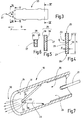
- the instrument 10 is connected to a device 11 which contains a gas source 12, for example an argon source, as well as a generator 13 for the electrical supply of the instrument 10. This is connected via corresponding connection means to a line 14 which leads to the instrument 10 and which is inserted into a line 15 via which the instrument 10 is supplied with gas.
- the generator 13 is also connected via corresponding connecting means to a neutral electrode 16, which is to be attached to the patient before the instrument 10 is used.
- the following description also applies to instruments with a different neutral electrode configuration.
- the instrument 10 has a distal end 17 which is shown separately in Figure 2 is illustrated.
- the instrument 10 includes a tube or hose 18 which surrounds a lumen 19 which is open at the distal end 17 of the hose 18.
- the tube 18 can be seen with an inner or outer reinforcement, for example in the form of a ceramic sleeve, which is shown in FIG Figure 2 is not shown in detail.
- the hose 18 can thus be constructed in one or more layers. Examples of instruments with a ceramic sleeve inserted into the open end of the tube 18 are the WO 2005/046495 A1 refer to.
- An electrode 20 is arranged in the lumen 19, which electrode is electrically connected to a wire 21 belonging to the line 14 and extending through the lumen 19.
- the wire 21 can be welded to the electrode 20 or also mechanically, for example by crimping.
- the electrode 20 preferably has the in Figure 3 illustrated basic form. At its distal end, a sharp or at most slightly rounded tip 22 is formed on the electrode 20, the radius of curvature R ( Figure 2 ) is as small as possible and preferably less than a tenth of the transverse dimension q, which is to be measured transversely to the axial direction and largely corresponds to the inner diameter of the lumen 19.
- the electrode 20 is preferably designed in the form of a plate, that is to say its thickness is significantly less than its transverse dimension q. This results for example from Figure 4 which shows the cross section of the electrode 20 at the in Figure 3 dash-dotted line IV-IV shows.
- the thickness d is less than 1/5, preferably less than 1/10 of the transverse dimension q.
- the electrode 20 has two flat sides 23, 24 which are connected by narrow sides 25, 26. This results in an overall quadrangular, preferably rectangular cross-section Q, which is delimited by the flat sides 23, 24 and the narrow sides 25, 26.
- the square cross section can also be bent one or more times, for example in an S-shape.
- the electrode 20 has a tapering region in which the narrow sides 25, 26, which otherwise run parallel to one another, are arranged convergently towards the tip 22.
- the sections of the narrow sides 25, 26 which converge towards one another can, as Figure 3 shows, be straight or convex or concave. They define an angle ⁇ between each other, which is preferably in the range of 20 ° and 100 °.
- the cross section of the electrode 20 decreases towards the tip 22 in the distal direction D or in other words in the proximal direction P increases.
- the thickness d of the electrode 20 in the tapering region towards the tip 22 can be like that Figures 5 and 6 show remain constant. However, the thickness d can also decrease towards the tip 22. In any case, however, the transverse dimension Q decreases in the tapering area towards the tip 22.
- the electrode 20 consists entirely of a material with good thermal conductivity, such as, for example, tungsten, a hard metal, copper, aluminum or a combination of these materials.
- a material with good thermal conductivity such as, for example, tungsten, a hard metal, copper, aluminum or a combination of these materials.
- Metals and non-metallic electrically conductive materials such as DLC or combinations of metal and such materials can be used.
- the material used then has a thermal conductivity A which is greater, preferably significantly greater than the thermal conductivity of stainless steel.
- ⁇ ⁇ 50W / (m ⁇ K) ⁇ 100W / (m ⁇ K), ⁇ 200W / (m ⁇ K), ⁇ 300W / (m ⁇ K), ⁇ 400W / (m ⁇ K).
- the electrode 20 has a multilayer structure, as it is from the Figures 4 and 6 emerges.
- the electrode 20 has an electrode base body 27 which is connected to a heat dissipation device 28 at least on its flat sides 23, 24 but optionally also on its narrow sides 25, 26.
- this consists of a full-surface coating of the flat sides of the electrode base body 27 with thermally conductive coatings 29, 30.
- the base body 27 can be made from Stainless steel, while the coatings 29, 30 are made of a different material with better thermal conductivity and / or better electrical conductivity. Silver has proven to be particularly suitable for this.
- Possible other coatings are made of aluminum and / or copper and / or hard metal and / or DLC and / or tungsten and / or a layer, for example a metal layer with embedded CBN (cubic boron nitride), diamond powder or a similar material with good thermal conductivity.
- CBN cubic boron nitride
- the instrument described so far works as follows: As in Figure 7 As illustrated, the lumen 19 of the instrument 10 is flowed through by a gas stream 31 which originates from the gas source 12 in operation. This gas flow (preferably argon flow) streaks along both flat sides 23, 24 of the electrode 20. Via the wire 21, the electrode 20 is simultaneously fed with high-frequency electrical current.
- the working frequency of the generator 13 and thus the frequency of the current is preferably above 100 kHz, preferably above 300 kHz, more preferably above 500 kHz.
- the current leaves the electrode 20 at the tip 22 and an adjoining area thereof and forms a spark or a plasma 32 flowing to the biological tissue of the patient (not shown).
- the base 33 of the spark or plasma touches the narrow sides 25, 26 , but in particular the flat sides 23, 24 of the electrode 20, this base area 33 taking up at least 1/10 of the axial length (to be measured in the proximal direction) of that area of the electrode 20 in which the narrow sides 25, 26 diverge away from the tip 22.
- the coatings 29, 30 extend into this area and preferably as far as the tip 22. The spark or plasma current is thus electrically fed directly from the coating 29, 30.
- the thickness of the coatings 29, 30 can be relatively small. It has been shown that coatings as thin as 10 to 20 ⁇ m lead to a substantial increase in the service life of the electrode 20 and to a significantly reduced material removal from the same.
- the thickness of the coatings is preferably 20 ⁇ m, 30 ⁇ m or 50 ⁇ m, which results in a thermal resistance of over 400W / (m * K) with a thickness of the electrode of 0.1 mm, for example.
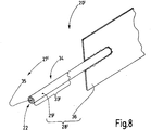
- the electrode 20 ' has a tip 22', which is here by the pointed or blunt end of a wire-shaped Electrode portion can be formed.
- This wire-shaped electrode section 34 contains a core 35 which forms the base body 27 'and in turn can be designed as a thin cylinder pin.
- the core 35 is provided with a coating 29 ', which here, optionally in conjunction with an electrode holding plate 36, forms the heat dissipation device 28'.
- the electrode section 34 can be welded, crimped or otherwise connected to the electrode holding plate 36. A material connection is preferred because of the better heat transfer.
- the electrode holding portion 36 can consist of stainless steel or another material which is provided with a thermally conductive coating such as tungsten, copper, aluminum, DLC or the like, or is formed from a thermally conductive material such as tungsten, copper, aluminum, DLC or the like.
- an electrical discharge and thus the spark or plasma current that is formed originate first from the tip 22 and then from at least part of the wire-shaped electrode section 34.
- the electrically and thermally conductive coating 29 ' which is preferably a silver coating, noticeably reduces the electrical resistance of the electrode 20 or 20'.
- the high-frequency alternating current of the generator 13 is concentrated in the outer layers of the electrode 20, 20 'and thus essentially flows through the coating 29, 30, 29'. This minimizes the ohmic losses at the electrode 20, 20 'and, in addition, the reduced amount of heat through the coating is conducted away from the discharge foot much better and distributed so that it can be transferred over a large area to the gas flow.
- the electrode 20, 20 ' is provided with a heat dissipation device 28, 28', so that the thermal resistance of the electrode 20, 20 'measured in the longitudinal direction (in the distal or proximal direction) is preferably ⁇ 300 W / (m * K) .
- the heat dissipation device 28, 28 ' is formed by a coating 29, 30, 29' which, compared to the material of the electrode base body 27, 27 ', has a higher electrical conductivity as well as a higher thermal conductivity.
Priority Applications (22)
| Application Number | Priority Date | Filing Date | Title |
|---|---|---|---|
| EP19187863.6A EP3769707A1 (fr) | 2019-07-23 | 2019-07-23 | Ensemble d'électrode |
| RU2020123442A RU2817637C2 (ru) | 2019-07-23 | 2020-07-15 | Электрод для электрохирургического инструмента |
| JP2022504044A JP2022541066A (ja) | 2019-07-23 | 2020-07-21 | 電極配置 |
| KR1020227004072A KR20220039730A (ko) | 2019-07-23 | 2020-07-21 | 전극 배열 |
| KR1020227004078A KR20220039732A (ko) | 2019-07-23 | 2020-07-21 | 전극 배열 |
| US17/628,727 US20220280219A1 (en) | 2019-07-23 | 2020-07-21 | Electrode arrangement |
| EP20740638.0A EP4003202A1 (fr) | 2019-07-23 | 2020-07-21 | Ensemble d'électrodes |
| PCT/EP2020/070580 WO2021013847A1 (fr) | 2019-07-23 | 2020-07-21 | Ensemble d'électrodes |
| PCT/EP2020/070567 WO2021013840A1 (fr) | 2019-07-23 | 2020-07-21 | Ensemble d'électrodes |
| CN202080052947.0A CN114126525A (zh) | 2019-07-23 | 2020-07-21 | 电极装置 |
| US17/628,709 US20220265336A1 (en) | 2019-07-23 | 2020-07-21 | Instrument for plasma surgery and method for generating plasma |
| JP2022504043A JP7476296B2 (ja) | 2019-07-23 | 2020-07-21 | 器具 |
| BR112021024172A BR112021024172A2 (pt) | 2019-07-23 | 2020-07-21 | Disposição de eletrodo |
| PCT/EP2020/070585 WO2021013852A1 (fr) | 2019-07-23 | 2020-07-21 | Instrument pour la chirurgie plasma et procédé pour produire un plasma |
| US17/628,666 US20220257302A1 (en) | 2019-07-23 | 2020-07-21 | Electrode arrangement |
| CN202080052940.9A CN114126524A (zh) | 2019-07-23 | 2020-07-21 | 等离子体外科手术仪器和等离子体生成方法 |
| JP2022504042A JP2022541599A (ja) | 2019-07-23 | 2020-07-21 | プラズマ手術用の器具およびプラズマを生成するための方法 |
| BR112021023591A BR112021023591A2 (pt) | 2019-07-23 | 2020-07-21 | Disposição de eletrodo |
| BR112021024096A BR112021024096A2 (pt) | 2019-07-23 | 2020-07-21 | Instrumento para cirurgia com plasma e processo para geração de plasma |
| KR1020227004075A KR20220039731A (ko) | 2019-07-23 | 2020-07-21 | 플라즈마 수술을 위한 기구 및 플라즈마 생성 방법 |
| EP20740640.6A EP4003203A1 (fr) | 2019-07-23 | 2020-07-21 | Instrument pour la chirurgie plasma et procédé pour produire un plasma |
| CN202080052895.7A CN114126523A (zh) | 2019-07-23 | 2020-07-21 | 电极装置 |
Applications Claiming Priority (1)
| Application Number | Priority Date | Filing Date | Title |
|---|---|---|---|
| EP19187863.6A EP3769707A1 (fr) | 2019-07-23 | 2019-07-23 | Ensemble d'électrode |
Publications (1)
| Publication Number | Publication Date |
|---|---|
| EP3769707A1 true EP3769707A1 (fr) | 2021-01-27 |
Family
ID=67438565
Family Applications (3)
| Application Number | Title | Priority Date | Filing Date |
|---|---|---|---|
| EP19187863.6A Pending EP3769707A1 (fr) | 2019-07-23 | 2019-07-23 | Ensemble d'électrode |
| EP20740638.0A Pending EP4003202A1 (fr) | 2019-07-23 | 2020-07-21 | Ensemble d'électrodes |
| EP20740640.6A Pending EP4003203A1 (fr) | 2019-07-23 | 2020-07-21 | Instrument pour la chirurgie plasma et procédé pour produire un plasma |
Family Applications After (2)
| Application Number | Title | Priority Date | Filing Date |
|---|---|---|---|
| EP20740638.0A Pending EP4003202A1 (fr) | 2019-07-23 | 2020-07-21 | Ensemble d'électrodes |
| EP20740640.6A Pending EP4003203A1 (fr) | 2019-07-23 | 2020-07-21 | Instrument pour la chirurgie plasma et procédé pour produire un plasma |
Country Status (7)
| Country | Link |
|---|---|
| US (3) | US20220280219A1 (fr) |
| EP (3) | EP3769707A1 (fr) |
| JP (2) | JP2022541066A (fr) |
| KR (3) | KR20220039732A (fr) |
| CN (3) | CN114126525A (fr) |
| BR (3) | BR112021023591A2 (fr) |
| WO (3) | WO2021013840A1 (fr) |
Cited By (1)
| Publication number | Priority date | Publication date | Assignee | Title |
|---|---|---|---|---|
| EP4119080A1 (fr) | 2021-07-12 | 2023-01-18 | Erbe Elektromedizin GmbH | Sonde plasma et procédé de montage de son électrode |
Families Citing this family (2)
| Publication number | Priority date | Publication date | Assignee | Title |
|---|---|---|---|---|
| EP4209188A1 (fr) * | 2022-01-07 | 2023-07-12 | Erbe Elektromedizin GmbH | Sonde à plasma |
| CN117165918B (zh) * | 2023-11-02 | 2024-02-20 | 成都仕康美医疗器械有限公司 | 一种降低组织焦痂的电外科器械用电极及其制备方法 |
Citations (6)
| Publication number | Priority date | Publication date | Assignee | Title |
|---|---|---|---|---|
| US5207675A (en) * | 1991-07-15 | 1993-05-04 | Jerome Canady | Surgical coagulation device |
| DE10030111A1 (de) | 2000-06-19 | 2002-01-03 | Erbe Elektromedizin | Sondenelektrode |
| WO2005046495A1 (fr) | 2003-11-04 | 2005-05-26 | Erbe Elektromedizin Gmbh | Instrument de coagulation au plasma |
| DE69928370T2 (de) | 1998-08-11 | 2006-08-03 | Arthrocare Corp., Sunnyvale | System und verfahren zur elektrochirurgischen gewebebehandlung in anwesenheit elektrisch leitender flüssigkeiten |
| DE102011116678A1 (de) | 2010-10-22 | 2012-05-10 | Arthrocare Corp. | Elektrochirurgisches System mit vorrichtungsspezifischen Betriebsparametern |
| DE102017127976A1 (de) * | 2016-12-20 | 2018-06-21 | Gyrus Medical Limited | Elektrochirurgische Vorrichtung |
Family Cites Families (6)
| Publication number | Priority date | Publication date | Assignee | Title |
|---|---|---|---|---|
| EP1850780B1 (fr) * | 2005-02-11 | 2012-06-20 | MacKay, Dale Victor | Sonde electrochirurgicale |
| US20070055226A1 (en) * | 2005-07-14 | 2007-03-08 | Garito Jon C | Electrosurgical electrode with silver |
| AU2012254836A1 (en) * | 2011-05-09 | 2013-12-19 | Ionmed Ltd | Medical device for tissue welding using plasma |
| US20150038790A1 (en) * | 2011-08-25 | 2015-02-05 | Michael Rontal | Method and apparatus for cold plasma treatment of internal organs |
| CN109152600A (zh) * | 2016-02-19 | 2019-01-04 | 梅迪登特科技股份有限公司 | 采用等离子弧流的组织治疗 |
| DE102016110705A1 (de) * | 2016-06-10 | 2017-12-14 | Olympus Winter & Ibe Gmbh | Elektrochirurgisches Instrument, elektrochirurgisches System und Verfahren zur Herstellung eines elektrochirurgischen Instruments |
-
2019
- 2019-07-23 EP EP19187863.6A patent/EP3769707A1/fr active Pending
-
2020
- 2020-07-21 CN CN202080052947.0A patent/CN114126525A/zh active Pending
- 2020-07-21 KR KR1020227004078A patent/KR20220039732A/ko unknown
- 2020-07-21 US US17/628,727 patent/US20220280219A1/en active Pending
- 2020-07-21 WO PCT/EP2020/070567 patent/WO2021013840A1/fr active Application Filing
- 2020-07-21 KR KR1020227004075A patent/KR20220039731A/ko unknown
- 2020-07-21 CN CN202080052895.7A patent/CN114126523A/zh active Pending
- 2020-07-21 CN CN202080052940.9A patent/CN114126524A/zh active Pending
- 2020-07-21 WO PCT/EP2020/070580 patent/WO2021013847A1/fr unknown
- 2020-07-21 BR BR112021023591A patent/BR112021023591A2/pt unknown
- 2020-07-21 JP JP2022504044A patent/JP2022541066A/ja active Pending
- 2020-07-21 EP EP20740638.0A patent/EP4003202A1/fr active Pending
- 2020-07-21 BR BR112021024172A patent/BR112021024172A2/pt unknown
- 2020-07-21 WO PCT/EP2020/070585 patent/WO2021013852A1/fr unknown
- 2020-07-21 JP JP2022504042A patent/JP2022541599A/ja active Pending
- 2020-07-21 BR BR112021024096A patent/BR112021024096A2/pt unknown
- 2020-07-21 KR KR1020227004072A patent/KR20220039730A/ko unknown
- 2020-07-21 US US17/628,709 patent/US20220265336A1/en active Pending
- 2020-07-21 US US17/628,666 patent/US20220257302A1/en active Pending
- 2020-07-21 EP EP20740640.6A patent/EP4003203A1/fr active Pending
Patent Citations (6)
| Publication number | Priority date | Publication date | Assignee | Title |
|---|---|---|---|---|
| US5207675A (en) * | 1991-07-15 | 1993-05-04 | Jerome Canady | Surgical coagulation device |
| DE69928370T2 (de) | 1998-08-11 | 2006-08-03 | Arthrocare Corp., Sunnyvale | System und verfahren zur elektrochirurgischen gewebebehandlung in anwesenheit elektrisch leitender flüssigkeiten |
| DE10030111A1 (de) | 2000-06-19 | 2002-01-03 | Erbe Elektromedizin | Sondenelektrode |
| WO2005046495A1 (fr) | 2003-11-04 | 2005-05-26 | Erbe Elektromedizin Gmbh | Instrument de coagulation au plasma |
| DE102011116678A1 (de) | 2010-10-22 | 2012-05-10 | Arthrocare Corp. | Elektrochirurgisches System mit vorrichtungsspezifischen Betriebsparametern |
| DE102017127976A1 (de) * | 2016-12-20 | 2018-06-21 | Gyrus Medical Limited | Elektrochirurgische Vorrichtung |
Cited By (1)
| Publication number | Priority date | Publication date | Assignee | Title |
|---|---|---|---|---|
| EP4119080A1 (fr) | 2021-07-12 | 2023-01-18 | Erbe Elektromedizin GmbH | Sonde plasma et procédé de montage de son électrode |
Also Published As
| Publication number | Publication date |
|---|---|
| JP2022540962A (ja) | 2022-09-20 |
| US20220280219A1 (en) | 2022-09-08 |
| EP4003203A1 (fr) | 2022-06-01 |
| US20220265336A1 (en) | 2022-08-25 |
| CN114126523A (zh) | 2022-03-01 |
| WO2021013847A1 (fr) | 2021-01-28 |
| KR20220039730A (ko) | 2022-03-29 |
| KR20220039731A (ko) | 2022-03-29 |
| BR112021024172A2 (pt) | 2022-03-22 |
| WO2021013840A1 (fr) | 2021-01-28 |
| WO2021013852A1 (fr) | 2021-01-28 |
| JP2022541599A (ja) | 2022-09-26 |
| RU2020123442A (ru) | 2022-01-17 |
| BR112021024096A2 (pt) | 2022-04-19 |
| BR112021023591A2 (pt) | 2022-01-04 |
| CN114126524A (zh) | 2022-03-01 |
| KR20220039732A (ko) | 2022-03-29 |
| US20220257302A1 (en) | 2022-08-18 |
| JP2022541066A (ja) | 2022-09-21 |
| EP4003202A1 (fr) | 2022-06-01 |
| CN114126525A (zh) | 2022-03-01 |
Similar Documents
| Publication | Publication Date | Title |
|---|---|---|
| EP3769707A1 (fr) | Ensemble d'électrode | |
| EP2948086B1 (fr) | Résectoscope bipolaire | |
| EP2140739B1 (fr) | Buse pour torche à plasma refroidie à liquide, dispositif comprenant cette buse et un capuchon pour buse, et torche à plasma refroidie à liquide présentant ledit dispositif | |
| DE60217083T2 (de) | Austrittsfenster für eine quelle zur emission von elektronenstrahlen | |
| EP3075340B1 (fr) | Ciseaux chirurgicaux pour tissus biologiques | |
| DE102004031141A1 (de) | Elektrochirurgisches Instrument | |
| DE10030111A1 (de) | Sondenelektrode | |
| EP2855071B1 (fr) | Chalumeau pour le soudage au tungstène et au gaz inerte | |
| EP2667689B1 (fr) | Électrode pour chalumeau de coupe au plasma ainsi que son utilisation | |
| EP2457681B1 (fr) | Torche pour le soudage au gaz inerte et électrode tungstène et électrode destinée à être utilisée dans une telle torche | |
| DE102007023494B4 (de) | Elektrode für die elektrochemische Bearbeitung eines metallischen Werkstücks | |
| DE2920277A1 (de) | Verfahren zur herstellung von metallbereichen auf einem metallstueck | |
| DE10351370A1 (de) | Instument für die Plasma-Koagulation | |
| DE10304936B3 (de) | Drehanode für eine Röntgenröhre mit einem Anodenkörper aus Faserwerkstoff sowie Verfahren zu deren Herstellung | |
| EP3173044B1 (fr) | Électrode chirurgicale de vaporisation | |
| DE19707696A1 (de) | Vorrichtung zur Bearbeitung mit elektrischer Entladung | |
| EP0239879B1 (fr) | Alimentation en courant pour le fil-électrode d'une machine d'électro-érosion | |
| DE102017127976A1 (de) | Elektrochirurgische Vorrichtung | |
| EP4119080A1 (fr) | Sonde plasma et procédé de montage de son électrode | |
| WO2013163994A1 (fr) | Résistance refroidie par un liquide | |
| DE102009015536A1 (de) | Keramischer Glühstift und Glühkerze | |
| EP3943029A1 (fr) | Sonde à plasma à comportement d'allumage amélioré | |
| EP3984480A1 (fr) | Sonde multivoies | |
| DE818536C (de) | Kathode, insbesondere fuer Elektronen-Entladungsgeraete | |
| DE202007016232U1 (de) | Chirurgisches Instrument |
Legal Events
| Date | Code | Title | Description |
|---|---|---|---|
| PUAI | Public reference made under article 153(3) epc to a published international application that has entered the european phase |
Free format text: ORIGINAL CODE: 0009012 |
|
| STAA | Information on the status of an ep patent application or granted ep patent |
Free format text: STATUS: THE APPLICATION HAS BEEN PUBLISHED |
|
| AK | Designated contracting states |
Kind code of ref document: A1 Designated state(s): AL AT BE BG CH CY CZ DE DK EE ES FI FR GB GR HR HU IE IS IT LI LT LU LV MC MK MT NL NO PL PT RO RS SE SI SK SM TR |
|
| AX | Request for extension of the european patent |
Extension state: BA ME |
|
| STAA | Information on the status of an ep patent application or granted ep patent |
Free format text: STATUS: REQUEST FOR EXAMINATION WAS MADE |
|
| 17P | Request for examination filed |
Effective date: 20210601 |
|
| RBV | Designated contracting states (corrected) |
Designated state(s): AL AT BE BG CH CY CZ DE DK EE ES FI FR GB GR HR HU IE IS IT LI LT LU LV MC MK MT NL NO PL PT RO RS SE SI SK SM TR |
|
| STAA | Information on the status of an ep patent application or granted ep patent |
Free format text: STATUS: EXAMINATION IS IN PROGRESS |
|
| 17Q | First examination report despatched |
Effective date: 20230922 |