EP3769405B1 - Elektrische verbindungsvorrichtung für eine drehende elektrische maschine - Google Patents
Elektrische verbindungsvorrichtung für eine drehende elektrische maschine Download PDFInfo
- Publication number
- EP3769405B1 EP3769405B1 EP19711393.9A EP19711393A EP3769405B1 EP 3769405 B1 EP3769405 B1 EP 3769405B1 EP 19711393 A EP19711393 A EP 19711393A EP 3769405 B1 EP3769405 B1 EP 3769405B1
- Authority
- EP
- European Patent Office
- Prior art keywords
- connection member
- external connection
- external
- frame
- internal
- Prior art date
- Legal status (The legal status is an assumption and is not a legal conclusion. Google has not performed a legal analysis and makes no representation as to the accuracy of the status listed.)
- Active
Links
Images



Classifications
-
- H—ELECTRICITY
- H02—GENERATION; CONVERSION OR DISTRIBUTION OF ELECTRIC POWER
- H02K—DYNAMO-ELECTRIC MACHINES
- H02K3/00—Details of windings
- H02K3/46—Fastening of windings on the stator or rotor structure
- H02K3/52—Fastening salient pole windings or connections thereto
- H02K3/521—Fastening salient pole windings or connections thereto applicable to stators only
- H02K3/522—Fastening salient pole windings or connections thereto applicable to stators only for generally annular cores with salient poles
-
- H—ELECTRICITY
- H02—GENERATION; CONVERSION OR DISTRIBUTION OF ELECTRIC POWER
- H02K—DYNAMO-ELECTRIC MACHINES
- H02K3/00—Details of windings
- H02K3/04—Windings characterised by the conductor shape, form or construction, e.g. with bar conductors
- H02K3/28—Layout of windings or of connections between windings
-
- H—ELECTRICITY
- H02—GENERATION; CONVERSION OR DISTRIBUTION OF ELECTRIC POWER
- H02K—DYNAMO-ELECTRIC MACHINES
- H02K5/00—Casings; Enclosures; Supports
- H02K5/04—Casings or enclosures characterised by the shape, form or construction thereof
- H02K5/22—Auxiliary parts of casings not covered by groups H02K5/06-H02K5/20, e.g. shaped to form connection boxes or terminal boxes
- H02K5/225—Terminal boxes or connection arrangements
-
- H—ELECTRICITY
- H02—GENERATION; CONVERSION OR DISTRIBUTION OF ELECTRIC POWER
- H02K—DYNAMO-ELECTRIC MACHINES
- H02K2203/00—Specific aspects not provided for in the other groups of this subclass relating to the windings
- H02K2203/09—Machines characterised by wiring elements other than wires, e.g. bus rings, for connecting the winding terminations
Definitions
- the technical field of the invention is that of rotating electrical machines such as motors, alternators and alternator-starters.
- the present invention relates to an electrical connection device for rotating electrical machines.
- the present invention also relates to a corresponding rotating electrical machine.
- the invention finds a particularly advantageous application in the field of alternator-starters used in so-called “hybrid” systems intended to participate in the propulsion of hybrid vehicles.
- hybrid systems comprise for this purpose a heat engine mechanically driving the electrical machine in rotation in alternator mode intended to provide, when necessary, electrical energy to supply batteries or the electrical machine can, in engine mode, participate in the propulsion of the vehicle.
- Rotating electrical machines comprising a stator and a rotor attached to a shaft in which each coil present on the stator is connected to a current source by electric cables made of a conductive material such as copper, often surrounded by an insulating sheath.
- a three-phase motor comprising three phases U, V and W
- a three-wire electric cable delivering a three-phase current and then, via a star or delta coupling, to connect each coil or each series of coils by a cable to the corresponding phase.
- the first coil, or series of coils will be connected to phase U, the second coil, or series of coils, to phase V and the third coil, or series of coils, to phase W.
- Rigid electrical connection systems of annular shape are known, as described in US patent application No. US 2008/0150377 (A1 ), which have connections to the coils on the outer periphery only or, as described in European Patent Application No. EP 2 677 634 (A1 ), which have connections on the internal periphery only.
- These electrical connection systems comprise four conductive rings stacked axially on top of each other and insulated from each other. Three of these rings are intended to be connected to the three phases U, V and W of the rotating electrical machine and a fourth ring is intended to be connected to the neutral of the machine.
- These electrical systems are intended to connect a rotating electrical machine to the electrical supply by a so-called star coupling. These systems do not allow the installation of other types of coupling and have a significant bulk due to the multiple connections arranged exclusively on one periphery of the system. These systems are composed of an assembly of dissimilar parts and therefore do not allow standardization either.
- the French patent FR 3 035 554 proposes an electrical connection system comprising, as in the solutions previously presented, several conductive rings stacked axially on top of each other and insulated from each other but each ring is composed of two conductive elements, a first conductive element arranged at the outer periphery of the ring and having connectors extending projecting towards the outside of the ring and a second conductive element arranged at the inner periphery of the ring and having connectors extending projecting towards the inside of the ring.
- connections are arranged on the two peripheries of the system which contributes to reducing the size and the risk of electrical proximity compared to the solutions previously described while allowing direct control of the phases of a rotating electrical machine, in particular using a double-bridge inverter.
- the demand US 2014/028127 A1 describes an electrical connection device comprising, several conductive rings stacked axially on each other and insulated from each other, the rings having a wavy shape forming troughs and peaks in the radial plane.
- the rings are configured to have connectors extending in projection on an inner periphery or respectively on an outer periphery of the electrical connection device.
- None of the current systems can simultaneously meet all the required needs, namely to allow direct control of the electrical phases of a rotating electrical machine with reduced bulk while minimizing the risks of overheating and malfunction.
- the device can establish an electrical connection with at least one coil whose input would be connected to the trace of the external connection member and the output to the trace of the internal connection member whose connections are made by means of connectors located at the external periphery and at the internal periphery of the device, which reduces the radial and/or axial size.
- the wavy shape of the traces also makes it possible to have rings with radial surfaces minimizing the risks of malfunction and overheating, by exploiting the hollows, by placing the connectors there.
- the connectors are thus sufficiently distant, because separated from a peak, without the radial surface of the traces having to be reduced, while optimizing the size.
- the device according to a first aspect of the invention may have one or more complementary characteristics among the following, considered individually or according to all technically possible combinations.
- the first external connection member is stacked axially on the internal connection member.
- first external connection member and the internal connection member are stacked on top of each other, on the same side of the stator.
- each trace has a wavy ring shape.
- the device is adapted to the shape of the stator of a rotating electrical machine.
- the traces are identical.
- each insulating envelope also covers at least one axial surface of the corresponding trace.
- the traces are electrically isolated from each other but also isolated from the outside.
- the hook or tab of a connector has an axial offset relative to the hollow in which the connector is electrically connected.
- the hook or tab can be located in the hollow of another trace, which limits the bulk.
- the device can establish an electrical connection with at least three sets of coils, which allows it to be used within a rotating electrical machine.
- the stacking of the three traces of the external connection members, each forming a phase of the stator makes it possible to produce the three phases of the stator.
- the second external connection member is stacked axially on the first external connection member and the third external connection member is stacked axially on the second external connection member.
- the three external connection members are stacked on top of each other, on the same side of the stator.
- the internal connection member can in this case be arranged on the other axial side of the stator or on the same axial side of the stator as the three stacked external connection members.
- the second external connection member is stacked axially on the first external connection member, itself stacked on the internal connection member and the third external connection member is stacked axially on the second external connection member.
- the three external connection members and the internal connection member are stacked on top of each other, on the same side of the stator.
- the device can establish an electrical connection with at least three sets of coils, which allows it to be used within a rotating electrical machine.
- the stacking of the three traces of the internal connection members, each forming a phase of the stator makes it possible to produce the three phases of the stator.
- the second internal connection member is stacked axially on the first internal connection member and the third internal connection member is stacked axially on the second internal connection member.
- first, second and third internal connection members are stacked on top of each other, on the same side of the stator.
- the first external connection member may in this case be arranged on the other axial side of the stator or on the same axial side of the stator as the three axially stacked internal connection members.
- the second internal connection member is axially stacked on the first internal connection member, itself stacked on the first external connection member and the third internal connection member is axially stacked on the second internal connection member.
- the three internal connection members and the external connection member are stacked on top of each other, on the same side of the stator.
- the internal connection member further comprises external connectors each electrically connected in an external hollow and in that the external connection member further comprises internal connectors each electrically connected in an internal hollow of the trace of the internal connection member.
- the device comprises a second external connection member or a second internal connection member.
- the device can establish an electrical connection with at least three sets of coils, which allows it to be used within a rotating electrical machine.
- a three-phase stator coupled in a delta there is the stacking of the three traces of the internal and external connection members, each forming a connection of two sets of coils to form an electrical phase output of the stator.
- the external connection members of the first embodiment of the invention or the internal connection members of the second embodiment are identical.
- the external connection organs are similar and can then be mass-produced using the same industrial process.
- the external or internal connection members are angularly offset from each other so that each connector of an external or internal connection member respectively is located axially opposite the external or internal hollows respectively devoid of connectors of the other external or internal connection members respectively.
- each external or internal connection member comprises an output connector intended to be connected to electrical equipment, for example a converter, and the external or internal connection members respectively are arranged one on top of the other with an angular offset so that the output connectors are spaced apart from each other by said angular offset.
- the connectors of the trace of a first external or internal connection member according to the embodiment and the connectors of the trace of a second external or internal connection member respectively stacked on the trace of the first external or internal connection member respectively are offset so as to space the connectors.
- access to the connectors is facilitated during soldering operations: the physical size and the electrical size are therefore reduced.
- the device according to the first aspect of the invention can be used within a three-phase rotating electrical machine which can have a star coupling or a delta coupling.
- the first, second and third sets of coils each comprise at least one corresponding coil having its input electrically connected respectively to the trace of the first, second and third external connection member and the output of at least one coil of each set of coils is electrically connected to the trace of the internal connection member by means of a connector of the internal connection member.
- the device according to a first aspect of the invention is used within a three-phase rotating electrical machine having a star coupling.
- the device according to the first aspect of the invention can be used within a three-phase rotating electrical machine having a star coupling.
- the device comprises at least one second external connection member and the two external connection members further comprise connectors electrically connected in an internal hollow of the corresponding trace and in that the internal connection member further comprises connectors electrically connected in an external hollow of the trace of the first external connection member and in that the inputs of each coil of the first, second and third set of coils are electrically connected to the connectors in the internal hollows respectively of the trace of the first and second external connection members and of the internal connection member and the outputs of each coil of the first, second and third set of coils are electrically connected to the connectors connected in the external hollows respectively of the trace of the second external connection member, of the internal connection member and of the first external connection member.
- the device according to the first aspect of the invention is used within a three-phase rotating electric machine having a delta coupling.
- input of a coil is meant the end of the cable or conductive wire of the coil furthest from the axis of the stator and by output of a coil is meant the other end of the cable or conductive wire of the coil closest to the axis of the stator.
- the external connection members and the internal connection member may have several traces in the same plane to allow coils of an assembly to be connected in series.
- each trace can have cut marks. This allows the traces to come from a single trace cut to form a plurality of traces.
- the coil input comprises a portion of cable, parallel to the X axis, located in the hollow in which the corresponding connector is electrically connected.
- the three-phase electrical component further comprises a converter performing the rectifier-inverter function, said converter comprising a first, a second and a third port, each respectively electrically connected to the trace of the first, second and third external or internal connection component depending on the embodiment, by means of the first, second and third phase input respectively.
- each of the phase inputs is electrically connected to the corresponding trace via the output connector of the corresponding external or internal connection member depending on the embodiment.
- the use of the converter allows the machine to operate in alternator mode with the rectifier function or in alternator mode with the inverter function.
- the trace of the internal or external connection member is electrically connected to the stator.
- the neutral is connected directly to the cylinder head, allowing a connection to be reduced between the electrical connection device and the three-phase electrical component.
- the rotating electrical machine according to a second aspect of the invention comprises a rotor comprising an external diameter, the connectors of each internally connected trace being located outside the external diameter of the rotor.
- the rotor can be mounted from both axial sides of the stator and the rotor can be made axially longer by protruding and being surrounded by the electrical connection device.
- the rotating electrical machine further comprises a fourth, a fifth and a sixth member of external or internal connection stacked axially with the first, second and third external or internal connection member according to the embodiments, and in that it further comprises a second three-phase electrical member electrically connected to the trace of the fourth, fifth and sixth external connection member.
- a first aspect of the invention relates to an electrical connection device intended to be used within a rotating electrical machine for the purpose of connecting it to the electrical power supply system.
- a rotating electrical machine is understood to mean a machine comprising a stator and a rotor, capable of operating in at least one of the following two modes: an alternator mode in which the machine produces electrical energy and a motor mode in which the machine produces mechanical energy corresponding to a torque.
- the device according to the first aspect of the invention comprises an internal connection member 100 shown in Figures 1a and 1b and a first external connection member 200 shown in Figures 2a and 2b .
- the internal connection member 100 comprises a trace 101 having a ring shape surrounding an axis X.
- This ring has undulations in its radial plane, having peaks and troughs 104, 105 on its inner periphery, towards the axis X and on its outer periphery, towards the outside.
- the troughs 104, 105 are identical and the peaks are identical.
- connectors 103 are electrically connected to the trace 101 of the internal connection member 100.
- the external connection member 200 comprises a trace 101 having a wavy ring shape, surrounding an axis X.
- the trace 101 of the internal connection member and the trace 101 of the external connection member are identical.
- connectors 103 are electrically connected to the trace 101 of the external connection member 200.
- the external connection member 200 is axially stacked with the internal connection member 100 along the X axis, which is not shown in Figures 1a, 1b , 2a and 2b .
- a first element is stacked with a second element means that the first element and the second element are in the same stack, as opposed to a first element is stacked on a second element which specifies that the first and second elements are arranged one on top of the other in the same stack.
- the external connection member 200 is, for example, separated from the internal connection member 100 by the stator of the rotating electrical machine, that is to say that the external connection member 200 is on one axial side of the stator and that the internal connection member 100 is on the other axial side of the stator.
- the external connection member 200 is stacked on the internal connection member 100.
- the external connection member 200 and the internal connection member 100 are located on the same side of the stator.
- Each trace 101 is covered with an insulating envelope 102 on at least one of its radial surfaces to allow electrical insulation between the stacked traces 101.
- the trace 101 of the internal connection member 100 and the trace 101 of the external connection member are each partially covered with an insulating envelope 102.
- the insulating envelope is formed of an insulating material such as, for example, a plastic material.
- the plastic material is, for example, polypropylene, more particularly PPs (Acronym for syndiotactic polypropylene) or PPa (Acronym for cellular polypropylene).
- the insulating envelope 102 also covers at least one axial surface of the trace 100 allowing its electrical insulation with the outside.
- the insulating envelope 102 covers the entirety of an axial surface of the external periphery and partially an axial surface of the internal periphery of the trace 101.
- the insulating envelope covers the part of the vertices of the internal periphery of the trace 101.
- the insulating envelope 102 covers the entirety of an axial surface of the inner periphery and partially an axial surface of the periphery external of trace 101.
- the insulating envelope covers the part of the vertices of the external periphery of trace 101.
- Traces 101 are formed of a conductive material.
- traces 101 are formed of a thin plate of copper, steel, or aluminum.
- the connectors 103 are for example formed of copper, steel or aluminum.
- the connectors 103 are intended to be connected to the input 301 or the output 302 of a coil, as shown in the Figures 4a and 4b .
- each connector 103 comprises a hook or a tab, the hook being particularly suitable for the case where the cable comprises one or more twisted wires and the tab in the case where the cable is welded using pin welding.
- the hooks or tabs are, for example, made of copper, steel or aluminium. In this case, the hooks or tabs are made of the same material as the traces.
- each hook or each tab of a connector 103 is axially offset relative to the hollow 104, 105 in which the connector 103 is connected.
- the connector 103 of a trace 101 can be found in the hollow 104, 105 of another trace 101.
- each internal hollow 105 of the trace 101 of the internal connection member 100 is connected to a connector 103, as shown in the Figures 1a and 1b .
- the external connection member 200 comprises an output connector 201, shown in the Figure 2a .
- the output connector 201 is of an elongated shape facing outwards so as to be able to be connected to electrical equipment, such as for example a converter or a power source.
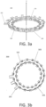
- a second external connection member 200 is stacked axially with the first external connection member 200, itself stacked with the internal connection member 100 and a third external connection member 200 is stacked axially with the second external connection member 200 to form an electrical connection device 300 shown in Figures 3a and 3b .
- the three external connection members 200 are arranged on the same side of the stator.
- the second external connection member 200 is stacked axially on the first external connection member 200, itself stacked on the internal connection member 100 and the third external connection member 200 is stacked axially on the second external connection member 200.
- the three external connection members 200 and the internal connection member 100 are arranged on the same side of the stator.
- the connectors 103 are distributed in such a way that two connectors 103 are not arranged along the same axis parallel to the axis X and that each hook or tab of a connector 103 can be found in the external hollow 104 of another external connection member 200.
- each external connection member 200 has a connector 103 in only one external recess 104 out of three, as shown in Figure 2a .
- Each connector 103 is then advantageously placed to be able to be connected to a coil.
- the connector 103 of the inner periphery and the connector 103 of the outer periphery intended to connect the same coil are angularly offset corresponding to a coil width.
- each external connection member 200 has a connector 103 in only one external recess 104 out of five.
- the device 300 can be used in a three-phase rotating electrical machine to allow direct control of the electrical phases of the rotating electrical machine.
- the rotating electrical machine comprises a three-phase electrical member comprising at least three electrical phase inputs, each being electrically connected to a trace 101 of one of the three external connection members 200 such that each trace 101 of the device 300 is connected to a different electrical phase input.
- the connection between a trace 101 of an external connection member 200 and an electrical phase input is made via the output connector 201 of the external connection member 200.
- the three-phase electrical member comprises a converter performing the rectifier-inverter function, comprising three ports, each being connected to a trace 101 of one of the three external connection members 200 via the corresponding electrical phase input.
- the rotating electric machine also includes a stator 400.
- the stator 400 shown in Figure 4a , comprises an iron casing which may be a sheet metal pack or a yoke, having grooves in which is located a polyphase winding comprising at least three sets of coils.
- a set of coils comprises at least one coil, each having an input 301 and an output 302.
- the coils of the same set of coils are connected in parallel.
- Each coil is electrically connected to a trace 101 of an external connection member 200 via its input 301, by means of a connector 103 of trace 101. This configuration subsequently allows the establishment of a triangle coupling or a star coupling.
- each coil is electrically connected to the trace 101 of the internal connection member 100 via its output 302, by means of a connector of the trace 101 of the internal connection member 100.
- the three-phase electric machine comprises a star coupling.
- the trace 101 of the internal connection member 100 is electrically connected to the stator 400.
- the portion of cable making up the input 301 of each coil is parallel to the axis X, located in the hollow 104, 105 in which the corresponding connector 103 is electrically connected.
- the electrical size is reduced.
- the rotating electrical machine also comprises a rotor having an external diameter.
- the connectors 103 of the internal connection member 100 are located outside the external diameter of the rotor.
- the rotor can be mounted by the two axial sides of the stator 400 allowing the rotor to be longer axially by protruding and to be surrounded by the device 300.
- the rotating electrical machine comprises a second three-phase electrical member and three external connection members 200 stacked axially between them are stacked on the device 300. It is then possible to produce, for example, a star coupling with six electrical phases. According to another embodiment not shown, it is of course possible to reverse the external connection members into internal connection members and the internal connection member into external connection member. In this case, there are therefore three internal connection members each comprising an output connector to be connected to a port of an inverter rectifier and the external connection member is connected to ground.
- connection member with its trace connected to the stator will be arranged on one side and the three connection members on the other side.
- the stator can comprise three connection members each comprising identical corrugated traces, each of the connection members comprising external connectors and internal connectors respectively electrically connected in the external hollows and the internal hollows of their corresponding trace.
- the stator can thus have a delta connection of the coil sets.
- Each coil of the coil sets comprises an output connected to an internal connector of a connection member and an input connected to an external connector of another connection member.
- the device can establish an electrical connection with at least three sets of coils, which allows it to be used within a rotating electrical machine.
- the stack of the three traces of the internal connection members each forming an electrical phase of the rotating electrical machine.
Landscapes
- Engineering & Computer Science (AREA)
- Power Engineering (AREA)
- Motor Or Generator Frames (AREA)
- Insulation, Fastening Of Motor, Generator Windings (AREA)
- Windings For Motors And Generators (AREA)
Claims (10)
- Elektrische Verbindungsvorrichtung, die aufweist:• ein eine Achse X umgebendes inneres Verbindungselement (100), das eine Spur (101), eine mindestens eine radiale Fläche der Spur (101) bedeckende Isolierhülle (102) und eine Vielzahl von elektrisch an die Spur (101) angeschlossenen Verbindern (103) aufweist, die geeignet sind, einen elektrischen Strom zu leiten; und• ein erstes äußeres Verbindungselement (200), das die Achse X umgibt und axial mit dem inneren Verbindungselement (100) gestapelt ist, wobei das erste äußere Verbindungselement (200) eine Spur (101), eine mindestens eine radiale Fläche der Spur (101) bedeckende Isolierhülle (102) und eine Vielzahl von elektrisch an die Spur (101) angeschlossenen Verbindern (103) aufweist;wobei jede Spur (101) eine gewellte Form aufweist, die Täler (104, 105) und Spitzen in der radialen Ebene formt, wobei die Täler (104, 105) innere Täler (105), die sich gegenüber der Achse X befinden, und äußere Täler (104) enthalten, die sich an einem äußeren Umfang der Spur (101) befinden, wobei die Vorrichtung dadurch gekennzeichnet ist, dass jeder Verbinder (103) des inneren Verbindungselements (100) elektrisch in einem inneren Tal (105) der Spur (101) des inneren Verbindungselements (100) angeschlossen ist, und jeder Verbinder (103) des ersten äußeren Verbindungselements (200) elektrisch in einem äußeren Tal (104) der Spur (101) des ersten äußeren Verbindungselements (200) angeschlossen ist.
- Vorrichtung nach Anspruch 1, dadurch gekennzeichnet, dass jede Spur (101) die Form eines gewellten Rings aufweist.
- Vorrichtung nach einem der vorhergehenden Ansprüche, dadurch gekennzeichnet, dass die Spuren (101) gleich sind.
- Vorrichtung (300) nach einem der vorhergehenden Ansprüche, dadurch gekennzeichnet, dass sie aufweist:• ein zweites äußeres Verbindungselement (200), das die Achse X umgibt und axial mit dem ersten äußeren Verbindungselement (200) gestapelt ist;• ein drittes äußeres Verbindungselement (200), das die Achse X umgibt und axial mit dem zweiten äußeren Verbindungselement (200) gestapelt ist.
- Vorrichtung (300) nach Anspruch 4, dadurch gekennzeichnet, dass die äußeren Verbindungselemente (200) gleich und winkelmäßig zueinander verschoben sind, so dass jeder Verbinder (103) eines äußeren Verbindungselements (200) sich axial gegenüber den äußeren Tälern (104) ohne Verbinder (103) der anderen äußeren Verbindungselemente (200) befindet.
- Vorrichtung (300) nach Anspruch 4 oder 5, dadurch gekennzeichnet, dass jedes äußere Verbindungselement (200) einen Ausgangsverbinder (201) aufweist, der dazu bestimmt ist, mit einer elektrischen Ausrüstung, zum Beispiel einem Wandler, verbunden zu werden, und die äußeren Verbindungselemente (200) übereinander mit einer Winkelverschiebung angeordnet sind, so dass die Ausgangsverbinder (201) zueinander sich um die Winkelverschiebung beabstandet sind.
- Rotierende elektrische Maschine, dadurch gekennzeichnet, dass sie aufweist:• eine elektrische Verbindungsvorrichtung (300) nach einem der Ansprüche 4 bis 6;• ein erstes dreiphasiges elektrisches Element, das mindestens einen ersten, einen zweiten und einen dritten elektrischen Phaseneingang aufweist;• einen Stator (400), der mit einer mehrphasigen Wicklung versehen ist, die mindestens eine erste, eine zweite und eine dritte Einheit von Spulen aufweist, wobei jede Einheit von Spulen Spulen enthält, wobei jede Spule einen Eingang (301) und einen Ausgang (302) aufweist,und dass die Spur (101) des ersten, zweiten und dritten äußeren Verbindungselements (200) elektrisch an den ersten, zweiten bzw. dritten elektrischen Phaseneingang angeschlossen ist, und dass die ersten, zweiten, dritten Einheiten von Spulen je mindestens eine entsprechende Spule enthalten, deren Eingang elektrisch an die Spur (101) des ersten, zweiten bzw. dritten äußeren Verbindungselements (200) über einen Verbinder (103) des äußeren Verbindungselements (200) angeschlossen ist.
- Rotierende elektrische Maschine nach Anspruch 7, dadurch gekennzeichnet, dass der Ausgang (302) mindestens einer Spule jeder Einheit von Spulen elektrisch an die Spur (101) des inneren Verbindungselements (100) über einen Verbinder (103) des inneren Verbindungselements (100) angeschlossen ist.
- Rotierende elektrische Maschine nach Anspruch 7 oder 8, dadurch gekennzeichnet, dass das dreiphasige elektrische Element außerdem einen Wandler aufweist, der die Funktion eines Gleichrichter-Wechselrichters erfüllt, wobei der Wandler einen ersten, einen zweiten und einen dritten Port aufweist, der elektrisch je mit der Spur (101) des ersten, zweiten und dritten äußeren Verbindungselement (200) über den ersten, zweiten bzw. dritten Phaseneingang verbunden ist.
- Rotierende elektrische Maschine nach einem der Ansprüche 7 bis 9 und Anspruch 6, dadurch gekennzeichnet, dass jeder der Phaseneingänge elektrisch mit der entsprechenden Spur (101) über den Ausgangsverbinder (201) des entsprechenden äußeren Verbindungselements (200) verbunden ist.
Applications Claiming Priority (2)
| Application Number | Priority Date | Filing Date | Title |
|---|---|---|---|
| FR1852508A FR3079368B1 (fr) | 2018-03-23 | 2018-03-23 | Dispositif de connexion electrique pour machine electrique tournante |
| PCT/EP2019/057308 WO2019180240A1 (fr) | 2018-03-23 | 2019-03-22 | Dispositif de connexion electrique pour machine electrique tournante |
Publications (2)
| Publication Number | Publication Date |
|---|---|
| EP3769405A1 EP3769405A1 (de) | 2021-01-27 |
| EP3769405B1 true EP3769405B1 (de) | 2025-01-08 |
Family
ID=63683958
Family Applications (1)
| Application Number | Title | Priority Date | Filing Date |
|---|---|---|---|
| EP19711393.9A Active EP3769405B1 (de) | 2018-03-23 | 2019-03-22 | Elektrische verbindungsvorrichtung für eine drehende elektrische maschine |
Country Status (6)
| Country | Link |
|---|---|
| US (1) | US20210066988A1 (de) |
| EP (1) | EP3769405B1 (de) |
| JP (1) | JP2021518735A (de) |
| CN (1) | CN111886781A (de) |
| FR (1) | FR3079368B1 (de) |
| WO (1) | WO2019180240A1 (de) |
Families Citing this family (1)
| Publication number | Priority date | Publication date | Assignee | Title |
|---|---|---|---|---|
| DE102018102033A1 (de) * | 2018-01-30 | 2019-08-01 | Ebm-Papst St. Georgen Gmbh & Co. Kg | Statorvorrichtung mit Verschalt-Endscheibe für einen Elektromotor und Verwendung der Statorvorrichtung |
Family Cites Families (19)
| Publication number | Priority date | Publication date | Assignee | Title |
|---|---|---|---|---|
| US4726159A (en) * | 1984-07-02 | 1988-02-23 | Consolidated Systems, Inc. | Composite metal/concrete floor and method |
| US5588843A (en) * | 1994-12-08 | 1996-12-31 | Hughes Aircraft Company | Rotary electrical connector |
| EP1401089A1 (de) * | 2002-09-18 | 2004-03-24 | Continental ISAD Electronic Systems GmbH & Co. KG | Elektrische Maschine, ausgebildet als Starter, Generator oder Starter-Generator für ein Kraftfahrzeug |
| JP2007049844A (ja) * | 2005-08-11 | 2007-02-22 | Shinano Kenshi Co Ltd | アウターロータ型モータ |
| JP4855239B2 (ja) | 2006-12-25 | 2012-01-18 | 三菱電線工業株式会社 | モータ用絶縁ハウジング |
| IT1397784B1 (it) * | 2010-01-15 | 2013-01-24 | Gate Srl | Collettore per lo statore di un motore brushless in corrente continua a magneti permanenti |
| FR2992495B1 (fr) * | 2012-06-20 | 2014-07-11 | Valeo Equip Electr Moteur | Interconnecteur pour stator de machine electrique et stator de machine electrique associe |
| US20140028127A1 (en) * | 2012-07-25 | 2014-01-30 | Bradley Duane Chamberlin | Buss bar assembly having alignment and retention feature |
| JP6190599B2 (ja) * | 2013-03-08 | 2017-08-30 | Kyb株式会社 | バスバーユニットの製造方法 |
| JP6011437B2 (ja) * | 2013-04-25 | 2016-10-19 | 日立金属株式会社 | 電動機の製造方法 |
| CN104505973A (zh) * | 2014-12-26 | 2015-04-08 | 山西汾西重工有限责任公司 | 防爆用多出线端子 |
| JP2016181944A (ja) * | 2015-03-23 | 2016-10-13 | 日立金属株式会社 | 集配電リング及び電動機 |
| JP2016208577A (ja) * | 2015-04-16 | 2016-12-08 | 日立金属株式会社 | 集配電リング及び電動機 |
| FR3035554B1 (fr) * | 2015-04-22 | 2019-03-22 | Valeo Equipements Electriques Moteur | Dispositif de connexion electrique pour machine electrique tournante et machine electrique tournante correspondante |
| WO2017013773A1 (ja) * | 2015-07-22 | 2017-01-26 | Kyb株式会社 | バスバーユニット、これを備えた回転電機及びバスバーユニットの製造方法 |
| DE102015214787B3 (de) * | 2015-08-03 | 2016-08-11 | Magna Powertrain Bad Homburg GmbH | Elektrischer Verdichter |
| CN205029458U (zh) * | 2015-09-28 | 2016-02-10 | 江苏雷利电机股份有限公司 | 电机线圈组件及应用其的小型电机 |
| WO2019065449A1 (ja) * | 2017-09-28 | 2019-04-04 | 日本電産株式会社 | モータ |
| DE102020203870A1 (de) * | 2020-01-24 | 2021-07-29 | Brose Fahrzeugteile SE & Co. Kommanditgesellschaft, Würzburg | Stator mit einer Kontaktvorrichtung |
-
2018
- 2018-03-23 FR FR1852508A patent/FR3079368B1/fr active Active
-
2019
- 2019-03-22 EP EP19711393.9A patent/EP3769405B1/de active Active
- 2019-03-22 JP JP2020551299A patent/JP2021518735A/ja not_active Ceased
- 2019-03-22 WO PCT/EP2019/057308 patent/WO2019180240A1/fr not_active Ceased
- 2019-03-22 US US16/982,799 patent/US20210066988A1/en not_active Abandoned
- 2019-03-22 CN CN201980020932.3A patent/CN111886781A/zh active Pending
Also Published As
| Publication number | Publication date |
|---|---|
| FR3079368A1 (fr) | 2019-09-27 |
| US20210066988A1 (en) | 2021-03-04 |
| CN111886781A (zh) | 2020-11-03 |
| EP3769405A1 (de) | 2021-01-27 |
| WO2019180240A1 (fr) | 2019-09-26 |
| FR3079368B1 (fr) | 2020-05-08 |
| JP2021518735A (ja) | 2021-08-02 |
Similar Documents
| Publication | Publication Date | Title |
|---|---|---|
| US6369473B1 (en) | Stator for an electrical machine and method for production of a stator | |
| EP3084932B1 (de) | Verbindung für einen stator einer elektrischen maschine sowie stator einer elektrischen maschine mit solch einem verbinder | |
| WO2017118786A1 (fr) | Stator pour machine electrique tournante | |
| EP3123597B1 (de) | Verbindungselement zur verbindung von statorspulen | |
| WO2019105975A1 (fr) | Connecteur de phase electrique pour stator de machine electrique tournante | |
| EP1269604B1 (de) | Elektrischer verbinder mit mehrfachkontaktelementen und drehende elektrische maschine mit einem solchen verbinder | |
| EP2740198B1 (de) | Verbinder, stromrichter mit einem solchen verbinder sowie mit einem solchen stromrichter ausgestattete elektromaschine | |
| FR3035554A1 (fr) | Dispositif de connexion electrique pour machine electrique tournante et machine electrique tournante correspondante | |
| EP2184835B1 (de) | Elektrische umlaufende Maschine | |
| EP2740199A1 (de) | Verbinder, stromrichter mit einem solchen verbinder sowie mit einem solchen stromrichter ausgestattete elektromaschine | |
| EP3322612B1 (de) | Drehende elektrische maschine für ein fahrzeug | |
| FR3084538A1 (fr) | Machine electrique tournante | |
| WO2019180240A1 (fr) | Dispositif de connexion electrique pour machine electrique tournante | |
| EP4169149A1 (de) | Anordnung mit einer elektrischen drehmaschine, einem verbinder und einem elektronischen modul | |
| EP4122082B1 (de) | Baugruppe bestehend aus einer rotierenden elektrischen maschine, einem elektronikmodul und einem verbinder | |
| FR2938131A1 (fr) | Machine electrique tournante comportant un organe d'isolation electrique | |
| FR3075503B1 (fr) | Stator pour machine electrique tournante | |
| WO2025186333A1 (fr) | Dispositif de connexion électrique de deux stators de moteur électrique à flux axial | |
| FR3152674A1 (fr) | Machine électrique à flux axial et procédé de montage correspondant | |
| FR3151947A1 (fr) | Collecteur électrique tournant d’un rotor bobiné et ensemble rotor le comprenant | |
| FR2938132A1 (fr) | Machine electrique tournante. | |
| FR3092446A1 (fr) | Connecteur électrique pour machine électrique tournante d’un véhicule automobile | |
| FR3065842A1 (fr) | Machine electrique tournante munie d'un stator | |
| FR3065593A1 (fr) | Machine electrique tournante a faible bruit | |
| FR2869730A1 (fr) | Dispositif de connexion electrique a contacts multiples ainsi que faisceau de cables electriques, embase et connecteur confectionnes en conformite avec un tel dispositif |
Legal Events
| Date | Code | Title | Description |
|---|---|---|---|
| STAA | Information on the status of an ep patent application or granted ep patent |
Free format text: STATUS: UNKNOWN |
|
| STAA | Information on the status of an ep patent application or granted ep patent |
Free format text: STATUS: THE INTERNATIONAL PUBLICATION HAS BEEN MADE |
|
| PUAI | Public reference made under article 153(3) epc to a published international application that has entered the european phase |
Free format text: ORIGINAL CODE: 0009012 |
|
| STAA | Information on the status of an ep patent application or granted ep patent |
Free format text: STATUS: REQUEST FOR EXAMINATION WAS MADE |
|
| 17P | Request for examination filed |
Effective date: 20200831 |
|
| AK | Designated contracting states |
Kind code of ref document: A1 Designated state(s): AL AT BE BG CH CY CZ DE DK EE ES FI FR GB GR HR HU IE IS IT LI LT LU LV MC MK MT NL NO PL PT RO RS SE SI SK SM TR |
|
| AX | Request for extension of the european patent |
Extension state: BA ME |
|
| DAV | Request for validation of the european patent (deleted) | ||
| DAX | Request for extension of the european patent (deleted) | ||
| GRAP | Despatch of communication of intention to grant a patent |
Free format text: ORIGINAL CODE: EPIDOSNIGR1 |
|
| STAA | Information on the status of an ep patent application or granted ep patent |
Free format text: STATUS: GRANT OF PATENT IS INTENDED |
|
| INTG | Intention to grant announced |
Effective date: 20220511 |
|
| GRAJ | Information related to disapproval of communication of intention to grant by the applicant or resumption of examination proceedings by the epo deleted |
Free format text: ORIGINAL CODE: EPIDOSDIGR1 |
|
| STAA | Information on the status of an ep patent application or granted ep patent |
Free format text: STATUS: REQUEST FOR EXAMINATION WAS MADE |
|
| STAA | Information on the status of an ep patent application or granted ep patent |
Free format text: STATUS: EXAMINATION IS IN PROGRESS |
|
| INTC | Intention to grant announced (deleted) | ||
| 17Q | First examination report despatched |
Effective date: 20220920 |
|
| GRAP | Despatch of communication of intention to grant a patent |
Free format text: ORIGINAL CODE: EPIDOSNIGR1 |
|
| STAA | Information on the status of an ep patent application or granted ep patent |
Free format text: STATUS: GRANT OF PATENT IS INTENDED |
|
| INTG | Intention to grant announced |
Effective date: 20240117 |
|
| GRAJ | Information related to disapproval of communication of intention to grant by the applicant or resumption of examination proceedings by the epo deleted |
Free format text: ORIGINAL CODE: EPIDOSDIGR1 |
|
| STAA | Information on the status of an ep patent application or granted ep patent |
Free format text: STATUS: EXAMINATION IS IN PROGRESS |
|
| INTC | Intention to grant announced (deleted) | ||
| RAP1 | Party data changed (applicant data changed or rights of an application transferred) |
Owner name: VALEO ELECTRIFICATION |
|
| GRAP | Despatch of communication of intention to grant a patent |
Free format text: ORIGINAL CODE: EPIDOSNIGR1 |
|
| STAA | Information on the status of an ep patent application or granted ep patent |
Free format text: STATUS: GRANT OF PATENT IS INTENDED |
|
| INTG | Intention to grant announced |
Effective date: 20240806 |
|
| P01 | Opt-out of the competence of the unified patent court (upc) registered |
Free format text: CASE NUMBER: APP_56569/2024 Effective date: 20241016 |
|
| GRAS | Grant fee paid |
Free format text: ORIGINAL CODE: EPIDOSNIGR3 |
|
| GRAA | (expected) grant |
Free format text: ORIGINAL CODE: 0009210 |
|
| STAA | Information on the status of an ep patent application or granted ep patent |
Free format text: STATUS: THE PATENT HAS BEEN GRANTED |
|
| AK | Designated contracting states |
Kind code of ref document: B1 Designated state(s): AL AT BE BG CH CY CZ DE DK EE ES FI FR GB GR HR HU IE IS IT LI LT LU LV MC MK MT NL NO PL PT RO RS SE SI SK SM TR |
|
| REG | Reference to a national code |
Ref country code: GB Ref legal event code: FG4D Free format text: NOT ENGLISH |
|
| REG | Reference to a national code |
Ref country code: CH Ref legal event code: EP |
|
| REG | Reference to a national code |
Ref country code: DE Ref legal event code: R096 Ref document number: 602019064572 Country of ref document: DE |
|
| REG | Reference to a national code |
Ref country code: IE Ref legal event code: FG4D Free format text: LANGUAGE OF EP DOCUMENT: FRENCH |
|
| REG | Reference to a national code |
Ref country code: LT Ref legal event code: MG9D |
|
| REG | Reference to a national code |
Ref country code: NL Ref legal event code: MP Effective date: 20250108 |
|
| REG | Reference to a national code |
Ref country code: AT Ref legal event code: MK05 Ref document number: 1758976 Country of ref document: AT Kind code of ref document: T Effective date: 20250108 |
|
| PG25 | Lapsed in a contracting state [announced via postgrant information from national office to epo] |
Ref country code: NL Free format text: LAPSE BECAUSE OF FAILURE TO SUBMIT A TRANSLATION OF THE DESCRIPTION OR TO PAY THE FEE WITHIN THE PRESCRIBED TIME-LIMIT Effective date: 20250108 |
|
| PG25 | Lapsed in a contracting state [announced via postgrant information from national office to epo] |
Ref country code: RS Free format text: LAPSE BECAUSE OF FAILURE TO SUBMIT A TRANSLATION OF THE DESCRIPTION OR TO PAY THE FEE WITHIN THE PRESCRIBED TIME-LIMIT Effective date: 20250408 |
|
| PG25 | Lapsed in a contracting state [announced via postgrant information from national office to epo] |
Ref country code: FI Free format text: LAPSE BECAUSE OF FAILURE TO SUBMIT A TRANSLATION OF THE DESCRIPTION OR TO PAY THE FEE WITHIN THE PRESCRIBED TIME-LIMIT Effective date: 20250108 |
|
| PG25 | Lapsed in a contracting state [announced via postgrant information from national office to epo] |
Ref country code: PL Free format text: LAPSE BECAUSE OF FAILURE TO SUBMIT A TRANSLATION OF THE DESCRIPTION OR TO PAY THE FEE WITHIN THE PRESCRIBED TIME-LIMIT Effective date: 20250108 |
|
| PG25 | Lapsed in a contracting state [announced via postgrant information from national office to epo] |
Ref country code: ES Free format text: LAPSE BECAUSE OF FAILURE TO SUBMIT A TRANSLATION OF THE DESCRIPTION OR TO PAY THE FEE WITHIN THE PRESCRIBED TIME-LIMIT Effective date: 20250108 |
|
| PG25 | Lapsed in a contracting state [announced via postgrant information from national office to epo] |
Ref country code: NO Free format text: LAPSE BECAUSE OF FAILURE TO SUBMIT A TRANSLATION OF THE DESCRIPTION OR TO PAY THE FEE WITHIN THE PRESCRIBED TIME-LIMIT Effective date: 20250408 Ref country code: IS Free format text: LAPSE BECAUSE OF FAILURE TO SUBMIT A TRANSLATION OF THE DESCRIPTION OR TO PAY THE FEE WITHIN THE PRESCRIBED TIME-LIMIT Effective date: 20250508 |
|
| PG25 | Lapsed in a contracting state [announced via postgrant information from national office to epo] |
Ref country code: HR Free format text: LAPSE BECAUSE OF FAILURE TO SUBMIT A TRANSLATION OF THE DESCRIPTION OR TO PAY THE FEE WITHIN THE PRESCRIBED TIME-LIMIT Effective date: 20250108 |
|
| PG25 | Lapsed in a contracting state [announced via postgrant information from national office to epo] |
Ref country code: PT Free format text: LAPSE BECAUSE OF FAILURE TO SUBMIT A TRANSLATION OF THE DESCRIPTION OR TO PAY THE FEE WITHIN THE PRESCRIBED TIME-LIMIT Effective date: 20250508 Ref country code: LV Free format text: LAPSE BECAUSE OF FAILURE TO SUBMIT A TRANSLATION OF THE DESCRIPTION OR TO PAY THE FEE WITHIN THE PRESCRIBED TIME-LIMIT Effective date: 20250108 |
|
| PG25 | Lapsed in a contracting state [announced via postgrant information from national office to epo] |
Ref country code: BG Free format text: LAPSE BECAUSE OF FAILURE TO SUBMIT A TRANSLATION OF THE DESCRIPTION OR TO PAY THE FEE WITHIN THE PRESCRIBED TIME-LIMIT Effective date: 20250108 Ref country code: GR Free format text: LAPSE BECAUSE OF FAILURE TO SUBMIT A TRANSLATION OF THE DESCRIPTION OR TO PAY THE FEE WITHIN THE PRESCRIBED TIME-LIMIT Effective date: 20250409 |
|
| PG25 | Lapsed in a contracting state [announced via postgrant information from national office to epo] |
Ref country code: AT Free format text: LAPSE BECAUSE OF FAILURE TO SUBMIT A TRANSLATION OF THE DESCRIPTION OR TO PAY THE FEE WITHIN THE PRESCRIBED TIME-LIMIT Effective date: 20250108 |
|
| PG25 | Lapsed in a contracting state [announced via postgrant information from national office to epo] |
Ref country code: SE Free format text: LAPSE BECAUSE OF FAILURE TO SUBMIT A TRANSLATION OF THE DESCRIPTION OR TO PAY THE FEE WITHIN THE PRESCRIBED TIME-LIMIT Effective date: 20250108 |
|
| PG25 | Lapsed in a contracting state [announced via postgrant information from national office to epo] |
Ref country code: SM Free format text: LAPSE BECAUSE OF FAILURE TO SUBMIT A TRANSLATION OF THE DESCRIPTION OR TO PAY THE FEE WITHIN THE PRESCRIBED TIME-LIMIT Effective date: 20250108 |
|
| REG | Reference to a national code |
Ref country code: DE Ref legal event code: R097 Ref document number: 602019064572 Country of ref document: DE |
|
| PG25 | Lapsed in a contracting state [announced via postgrant information from national office to epo] |
Ref country code: DK Free format text: LAPSE BECAUSE OF FAILURE TO SUBMIT A TRANSLATION OF THE DESCRIPTION OR TO PAY THE FEE WITHIN THE PRESCRIBED TIME-LIMIT Effective date: 20250108 |
|
| PG25 | Lapsed in a contracting state [announced via postgrant information from national office to epo] |
Ref country code: MC Free format text: LAPSE BECAUSE OF FAILURE TO SUBMIT A TRANSLATION OF THE DESCRIPTION OR TO PAY THE FEE WITHIN THE PRESCRIBED TIME-LIMIT Effective date: 20250108 |
|
| PG25 | Lapsed in a contracting state [announced via postgrant information from national office to epo] |
Ref country code: EE Free format text: LAPSE BECAUSE OF FAILURE TO SUBMIT A TRANSLATION OF THE DESCRIPTION OR TO PAY THE FEE WITHIN THE PRESCRIBED TIME-LIMIT Effective date: 20250108 Ref country code: CZ Free format text: LAPSE BECAUSE OF FAILURE TO SUBMIT A TRANSLATION OF THE DESCRIPTION OR TO PAY THE FEE WITHIN THE PRESCRIBED TIME-LIMIT Effective date: 20250108 |
|
| PG25 | Lapsed in a contracting state [announced via postgrant information from national office to epo] |
Ref country code: RO Free format text: LAPSE BECAUSE OF FAILURE TO SUBMIT A TRANSLATION OF THE DESCRIPTION OR TO PAY THE FEE WITHIN THE PRESCRIBED TIME-LIMIT Effective date: 20250108 |
|
| REG | Reference to a national code |
Ref country code: CH Ref legal event code: H13 Free format text: ST27 STATUS EVENT CODE: U-0-0-H10-H13 (AS PROVIDED BY THE NATIONAL OFFICE) Effective date: 20251023 |
|
| PG25 | Lapsed in a contracting state [announced via postgrant information from national office to epo] |
Ref country code: SK Free format text: LAPSE BECAUSE OF FAILURE TO SUBMIT A TRANSLATION OF THE DESCRIPTION OR TO PAY THE FEE WITHIN THE PRESCRIBED TIME-LIMIT Effective date: 20250108 |
|
| PLBE | No opposition filed within time limit |
Free format text: ORIGINAL CODE: 0009261 |
|
| STAA | Information on the status of an ep patent application or granted ep patent |
Free format text: STATUS: NO OPPOSITION FILED WITHIN TIME LIMIT |
|
| PG25 | Lapsed in a contracting state [announced via postgrant information from national office to epo] |
Ref country code: LU Free format text: LAPSE BECAUSE OF NON-PAYMENT OF DUE FEES Effective date: 20250322 |
|
| REG | Reference to a national code |
Ref country code: BE Ref legal event code: MM Effective date: 20250331 |
|
| 26N | No opposition filed |
Effective date: 20251009 |
|
| GBPC | Gb: european patent ceased through non-payment of renewal fee |
Effective date: 20250408 |
|
| PG25 | Lapsed in a contracting state [announced via postgrant information from national office to epo] |
Ref country code: GB Free format text: LAPSE BECAUSE OF NON-PAYMENT OF DUE FEES Effective date: 20250408 |
|
| PG25 | Lapsed in a contracting state [announced via postgrant information from national office to epo] |
Ref country code: BE Free format text: LAPSE BECAUSE OF NON-PAYMENT OF DUE FEES Effective date: 20250331 |
|
| PG25 | Lapsed in a contracting state [announced via postgrant information from national office to epo] |
Ref country code: CH Free format text: LAPSE BECAUSE OF NON-PAYMENT OF DUE FEES Effective date: 20250331 |
|
| PG25 | Lapsed in a contracting state [announced via postgrant information from national office to epo] |
Ref country code: IE Free format text: LAPSE BECAUSE OF NON-PAYMENT OF DUE FEES Effective date: 20250322 |
|
| PG25 | Lapsed in a contracting state [announced via postgrant information from national office to epo] |
Ref country code: IT Free format text: LAPSE BECAUSE OF FAILURE TO SUBMIT A TRANSLATION OF THE DESCRIPTION OR TO PAY THE FEE WITHIN THE PRESCRIBED TIME-LIMIT Effective date: 20250108 |
|
| PGFP | Annual fee paid to national office [announced via postgrant information from national office to epo] |
Ref country code: DE Payment date: 20260313 Year of fee payment: 8 |
|
| PGFP | Annual fee paid to national office [announced via postgrant information from national office to epo] |
Ref country code: FR Payment date: 20260331 Year of fee payment: 8 |