EP3765716B1 - Use of recovered power in a process - Google Patents
Use of recovered power in a process Download PDFInfo
- Publication number
- EP3765716B1 EP3765716B1 EP19767446.8A EP19767446A EP3765716B1 EP 3765716 B1 EP3765716 B1 EP 3765716B1 EP 19767446 A EP19767446 A EP 19767446A EP 3765716 B1 EP3765716 B1 EP 3765716B1
- Authority
- EP
- European Patent Office
- Prior art keywords
- power
- stream
- direct current
- zone
- pressure reducing
- Prior art date
- Legal status (The legal status is an assumption and is not a legal conclusion. Google has not performed a legal analysis and makes no representation as to the accuracy of the status listed.)
- Active
Links
- 238000000034 method Methods 0.000 title claims description 99
- 230000008569 process Effects 0.000 title claims description 97
- 238000011084 recovery Methods 0.000 claims description 66
- 239000003208 petroleum Substances 0.000 claims description 31
- 238000001311 chemical methods and process Methods 0.000 claims description 29
- 239000012530 fluid Substances 0.000 claims description 20
- 238000003860 storage Methods 0.000 claims description 19
- UHOVQNZJYSORNB-UHFFFAOYSA-N Benzene Chemical compound C1=CC=CC=C1 UHOVQNZJYSORNB-UHFFFAOYSA-N 0.000 description 96
- 230000005611 electricity Effects 0.000 description 17
- 239000008096 xylene Substances 0.000 description 13
- CTQNGGLPUBDAKN-UHFFFAOYSA-N O-Xylene Chemical compound CC1=CC=CC=C1C CTQNGGLPUBDAKN-UHFFFAOYSA-N 0.000 description 11
- 238000004886 process control Methods 0.000 description 10
- 238000004821 distillation Methods 0.000 description 9
- 238000012545 processing Methods 0.000 description 9
- 238000000926 separation method Methods 0.000 description 9
- 238000006243 chemical reaction Methods 0.000 description 7
- YXFVVABEGXRONW-UHFFFAOYSA-N Toluene Chemical compound CC1=CC=CC=C1 YXFVVABEGXRONW-UHFFFAOYSA-N 0.000 description 6
- 239000002737 fuel gas Substances 0.000 description 6
- 239000000047 product Substances 0.000 description 6
- 230000000274 adsorptive effect Effects 0.000 description 5
- 238000013459 approach Methods 0.000 description 5
- 230000005540 biological transmission Effects 0.000 description 5
- 238000004891 communication Methods 0.000 description 5
- IJGRMHOSHXDMSA-UHFFFAOYSA-N Atomic nitrogen Chemical compound N#N IJGRMHOSHXDMSA-UHFFFAOYSA-N 0.000 description 4
- 230000001276 controlling effect Effects 0.000 description 4
- 238000013461 design Methods 0.000 description 4
- 239000007789 gas Substances 0.000 description 4
- 238000009434 installation Methods 0.000 description 4
- 238000004519 manufacturing process Methods 0.000 description 4
- XLYOFNOQVPJJNP-UHFFFAOYSA-N water Substances O XLYOFNOQVPJJNP-UHFFFAOYSA-N 0.000 description 4
- 230000003750 conditioning effect Effects 0.000 description 3
- 239000000446 fuel Substances 0.000 description 3
- 230000006870 function Effects 0.000 description 3
- 238000003306 harvesting Methods 0.000 description 3
- 238000010438 heat treatment Methods 0.000 description 3
- 239000007788 liquid Substances 0.000 description 3
- 230000004048 modification Effects 0.000 description 3
- 238000012986 modification Methods 0.000 description 3
- 238000005457 optimization Methods 0.000 description 3
- 238000005086 pumping Methods 0.000 description 3
- 238000010992 reflux Methods 0.000 description 3
- 230000004044 response Effects 0.000 description 3
- 238000001179 sorption measurement Methods 0.000 description 3
- LFQSCWFLJHTTHZ-UHFFFAOYSA-N Ethanol Chemical compound CCO LFQSCWFLJHTTHZ-UHFFFAOYSA-N 0.000 description 2
- 150000001336 alkenes Chemical class 0.000 description 2
- 230000008901 benefit Effects 0.000 description 2
- 238000001833 catalytic reforming Methods 0.000 description 2
- 238000012993 chemical processing Methods 0.000 description 2
- 239000000498 cooling water Substances 0.000 description 2
- 238000006356 dehydrogenation reaction Methods 0.000 description 2
- 238000009826 distribution Methods 0.000 description 2
- 238000011156 evaluation Methods 0.000 description 2
- 238000005194 fractionation Methods 0.000 description 2
- 238000010348 incorporation Methods 0.000 description 2
- 229910052757 nitrogen Inorganic materials 0.000 description 2
- 238000010248 power generation Methods 0.000 description 2
- 230000009467 reduction Effects 0.000 description 2
- 150000003738 xylenes Chemical class 0.000 description 2
- 239000004215 Carbon black (E152) Substances 0.000 description 1
- RWSOTUBLDIXVET-UHFFFAOYSA-N Dihydrogen sulfide Chemical compound S RWSOTUBLDIXVET-UHFFFAOYSA-N 0.000 description 1
- 238000010521 absorption reaction Methods 0.000 description 1
- 230000029936 alkylation Effects 0.000 description 1
- 238000005804 alkylation reaction Methods 0.000 description 1
- 238000012550 audit Methods 0.000 description 1
- 230000033228 biological regulation Effects 0.000 description 1
- 239000003054 catalyst Substances 0.000 description 1
- 238000004517 catalytic hydrocracking Methods 0.000 description 1
- 230000008859 change Effects 0.000 description 1
- 238000004939 coking Methods 0.000 description 1
- 238000007596 consolidation process Methods 0.000 description 1
- 238000001816 cooling Methods 0.000 description 1
- 230000008878 coupling Effects 0.000 description 1
- 238000010168 coupling process Methods 0.000 description 1
- 238000005859 coupling reaction Methods 0.000 description 1
- 238000005336 cracking Methods 0.000 description 1
- 238000013480 data collection Methods 0.000 description 1
- 230000003247 decreasing effect Effects 0.000 description 1
- 238000006477 desulfuration reaction Methods 0.000 description 1
- 230000023556 desulfurization Effects 0.000 description 1
- 238000011143 downstream manufacturing Methods 0.000 description 1
- 238000005265 energy consumption Methods 0.000 description 1
- 230000007613 environmental effect Effects 0.000 description 1
- 238000000605 extraction Methods 0.000 description 1
- 238000000895 extractive distillation Methods 0.000 description 1
- RLQJEEJISHYWON-UHFFFAOYSA-N flonicamid Chemical compound FC(F)(F)C1=CC=NC=C1C(=O)NCC#N RLQJEEJISHYWON-UHFFFAOYSA-N 0.000 description 1
- 239000003502 gasoline Substances 0.000 description 1
- 229930195733 hydrocarbon Natural products 0.000 description 1
- 150000002430 hydrocarbons Chemical class 0.000 description 1
- 229910000037 hydrogen sulfide Inorganic materials 0.000 description 1
- 238000005984 hydrogenation reaction Methods 0.000 description 1
- 238000006317 isomerization reaction Methods 0.000 description 1
- 239000007791 liquid phase Substances 0.000 description 1
- 238000007726 management method Methods 0.000 description 1
- 239000000463 material Substances 0.000 description 1
- 238000006384 oligomerization reaction Methods 0.000 description 1
- 238000012856 packing Methods 0.000 description 1
- 239000012071 phase Substances 0.000 description 1
- 230000021715 photosynthesis, light harvesting Effects 0.000 description 1
- 238000006116 polymerization reaction Methods 0.000 description 1
- 238000005381 potential energy Methods 0.000 description 1
- 238000010791 quenching Methods 0.000 description 1
- 230000008929 regeneration Effects 0.000 description 1
- 238000011069 regeneration method Methods 0.000 description 1
- 230000001105 regulatory effect Effects 0.000 description 1
- -1 steam Substances 0.000 description 1
- 239000013589 supplement Substances 0.000 description 1
- 230000000153 supplemental effect Effects 0.000 description 1
- 230000001360 synchronised effect Effects 0.000 description 1
- 238000010555 transalkylation reaction Methods 0.000 description 1
- 238000012546 transfer Methods 0.000 description 1
- 230000009466 transformation Effects 0.000 description 1
- 238000010977 unit operation Methods 0.000 description 1
Images


Classifications
-
- B—PERFORMING OPERATIONS; TRANSPORTING
- B01—PHYSICAL OR CHEMICAL PROCESSES OR APPARATUS IN GENERAL
- B01D—SEPARATION
- B01D3/00—Distillation or related exchange processes in which liquids are contacted with gaseous media, e.g. stripping
- B01D3/007—Energy recuperation; Heat pumps
-
- B—PERFORMING OPERATIONS; TRANSPORTING
- B01—PHYSICAL OR CHEMICAL PROCESSES OR APPARATUS IN GENERAL
- B01D—SEPARATION
- B01D3/00—Distillation or related exchange processes in which liquids are contacted with gaseous media, e.g. stripping
- B01D3/14—Fractional distillation or use of a fractionation or rectification column
-
- C—CHEMISTRY; METALLURGY
- C07—ORGANIC CHEMISTRY
- C07C—ACYCLIC OR CARBOCYCLIC COMPOUNDS
- C07C7/00—Purification; Separation; Use of additives
- C07C7/04—Purification; Separation; Use of additives by distillation
-
- C—CHEMISTRY; METALLURGY
- C07—ORGANIC CHEMISTRY
- C07C—ACYCLIC OR CARBOCYCLIC COMPOUNDS
- C07C7/00—Purification; Separation; Use of additives
- C07C7/04—Purification; Separation; Use of additives by distillation
- C07C7/05—Purification; Separation; Use of additives by distillation with the aid of auxiliary compounds
- C07C7/08—Purification; Separation; Use of additives by distillation with the aid of auxiliary compounds by extractive distillation
-
- F—MECHANICAL ENGINEERING; LIGHTING; HEATING; WEAPONS; BLASTING
- F01—MACHINES OR ENGINES IN GENERAL; ENGINE PLANTS IN GENERAL; STEAM ENGINES
- F01D—NON-POSITIVE DISPLACEMENT MACHINES OR ENGINES, e.g. STEAM TURBINES
- F01D15/00—Adaptations of machines or engines for special use; Combinations of engines with devices driven thereby
- F01D15/10—Adaptations for driving, or combinations with, electric generators
-
- F—MECHANICAL ENGINEERING; LIGHTING; HEATING; WEAPONS; BLASTING
- F01—MACHINES OR ENGINES IN GENERAL; ENGINE PLANTS IN GENERAL; STEAM ENGINES
- F01D—NON-POSITIVE DISPLACEMENT MACHINES OR ENGINES, e.g. STEAM TURBINES
- F01D17/00—Regulating or controlling by varying flow
- F01D17/10—Final actuators
- F01D17/12—Final actuators arranged in stator parts
- F01D17/14—Final actuators arranged in stator parts varying effective cross-sectional area of nozzles or guide conduits
- F01D17/16—Final actuators arranged in stator parts varying effective cross-sectional area of nozzles or guide conduits by means of nozzle vanes
-
- F—MECHANICAL ENGINEERING; LIGHTING; HEATING; WEAPONS; BLASTING
- F01—MACHINES OR ENGINES IN GENERAL; ENGINE PLANTS IN GENERAL; STEAM ENGINES
- F01K—STEAM ENGINE PLANTS; STEAM ACCUMULATORS; ENGINE PLANTS NOT OTHERWISE PROVIDED FOR; ENGINES USING SPECIAL WORKING FLUIDS OR CYCLES
- F01K23/00—Plants characterised by more than one engine delivering power external to the plant, the engines being driven by different fluids
- F01K23/02—Plants characterised by more than one engine delivering power external to the plant, the engines being driven by different fluids the engine cycles being thermally coupled
- F01K23/06—Plants characterised by more than one engine delivering power external to the plant, the engines being driven by different fluids the engine cycles being thermally coupled combustion heat from one cycle heating the fluid in another cycle
- F01K23/064—Plants characterised by more than one engine delivering power external to the plant, the engines being driven by different fluids the engine cycles being thermally coupled combustion heat from one cycle heating the fluid in another cycle in combination with an industrial process, e.g. chemical, metallurgical
-
- H—ELECTRICITY
- H02—GENERATION; CONVERSION OR DISTRIBUTION OF ELECTRIC POWER
- H02J—CIRCUIT ARRANGEMENTS OR SYSTEMS FOR SUPPLYING OR DISTRIBUTING ELECTRIC POWER; SYSTEMS FOR STORING ELECTRIC ENERGY
- H02J7/00—Circuit arrangements for charging or depolarising batteries or for supplying loads from batteries
- H02J7/0068—Battery or charger load switching, e.g. concurrent charging and load supply
-
- F—MECHANICAL ENGINEERING; LIGHTING; HEATING; WEAPONS; BLASTING
- F01—MACHINES OR ENGINES IN GENERAL; ENGINE PLANTS IN GENERAL; STEAM ENGINES
- F01K—STEAM ENGINE PLANTS; STEAM ACCUMULATORS; ENGINE PLANTS NOT OTHERWISE PROVIDED FOR; ENGINES USING SPECIAL WORKING FLUIDS OR CYCLES
- F01K25/00—Plants or engines characterised by use of special working fluids, not otherwise provided for; Plants operating in closed cycles and not otherwise provided for
- F01K25/08—Plants or engines characterised by use of special working fluids, not otherwise provided for; Plants operating in closed cycles and not otherwise provided for using special vapours
- F01K25/14—Plants or engines characterised by use of special working fluids, not otherwise provided for; Plants operating in closed cycles and not otherwise provided for using special vapours using industrial or other waste gases
-
- F—MECHANICAL ENGINEERING; LIGHTING; HEATING; WEAPONS; BLASTING
- F05—INDEXING SCHEMES RELATING TO ENGINES OR PUMPS IN VARIOUS SUBCLASSES OF CLASSES F01-F04
- F05D—INDEXING SCHEME FOR ASPECTS RELATING TO NON-POSITIVE-DISPLACEMENT MACHINES OR ENGINES, GAS-TURBINES OR JET-PROPULSION PLANTS
- F05D2220/00—Application
- F05D2220/30—Application in turbines
- F05D2220/31—Application in turbines in steam turbines
-
- F—MECHANICAL ENGINEERING; LIGHTING; HEATING; WEAPONS; BLASTING
- F05—INDEXING SCHEMES RELATING TO ENGINES OR PUMPS IN VARIOUS SUBCLASSES OF CLASSES F01-F04
- F05D—INDEXING SCHEME FOR ASPECTS RELATING TO NON-POSITIVE-DISPLACEMENT MACHINES OR ENGINES, GAS-TURBINES OR JET-PROPULSION PLANTS
- F05D2220/00—Application
- F05D2220/60—Application making use of surplus or waste energy
- F05D2220/62—Application making use of surplus or waste energy with energy recovery turbines
-
- F—MECHANICAL ENGINEERING; LIGHTING; HEATING; WEAPONS; BLASTING
- F05—INDEXING SCHEMES RELATING TO ENGINES OR PUMPS IN VARIOUS SUBCLASSES OF CLASSES F01-F04
- F05D—INDEXING SCHEME FOR ASPECTS RELATING TO NON-POSITIVE-DISPLACEMENT MACHINES OR ENGINES, GAS-TURBINES OR JET-PROPULSION PLANTS
- F05D2220/00—Application
- F05D2220/70—Application in combination with
- F05D2220/76—Application in combination with an electrical generator
-
- F—MECHANICAL ENGINEERING; LIGHTING; HEATING; WEAPONS; BLASTING
- F05—INDEXING SCHEMES RELATING TO ENGINES OR PUMPS IN VARIOUS SUBCLASSES OF CLASSES F01-F04
- F05D—INDEXING SCHEME FOR ASPECTS RELATING TO NON-POSITIVE-DISPLACEMENT MACHINES OR ENGINES, GAS-TURBINES OR JET-PROPULSION PLANTS
- F05D2270/00—Control
- F05D2270/01—Purpose of the control system
- F05D2270/05—Purpose of the control system to affect the output of the engine
-
- Y—GENERAL TAGGING OF NEW TECHNOLOGICAL DEVELOPMENTS; GENERAL TAGGING OF CROSS-SECTIONAL TECHNOLOGIES SPANNING OVER SEVERAL SECTIONS OF THE IPC; TECHNICAL SUBJECTS COVERED BY FORMER USPC CROSS-REFERENCE ART COLLECTIONS [XRACs] AND DIGESTS
- Y02—TECHNOLOGIES OR APPLICATIONS FOR MITIGATION OR ADAPTATION AGAINST CLIMATE CHANGE
- Y02P—CLIMATE CHANGE MITIGATION TECHNOLOGIES IN THE PRODUCTION OR PROCESSING OF GOODS
- Y02P20/00—Technologies relating to chemical industry
- Y02P20/10—Process efficiency
- Y02P20/129—Energy recovery, e.g. by cogeneration, H2recovery or pressure recovery turbines
-
- Y—GENERAL TAGGING OF NEW TECHNOLOGICAL DEVELOPMENTS; GENERAL TAGGING OF CROSS-SECTIONAL TECHNOLOGIES SPANNING OVER SEVERAL SECTIONS OF THE IPC; TECHNICAL SUBJECTS COVERED BY FORMER USPC CROSS-REFERENCE ART COLLECTIONS [XRACs] AND DIGESTS
- Y02—TECHNOLOGIES OR APPLICATIONS FOR MITIGATION OR ADAPTATION AGAINST CLIMATE CHANGE
- Y02P—CLIMATE CHANGE MITIGATION TECHNOLOGIES IN THE PRODUCTION OR PROCESSING OF GOODS
- Y02P70/00—Climate change mitigation technologies in the production process for final industrial or consumer products
- Y02P70/10—Greenhouse gas [GHG] capture, material saving, heat recovery or other energy efficient measures, e.g. motor control, characterised by manufacturing processes, e.g. for rolling metal or metal working
Definitions
- Petroleum, petrochemical, and chemical processing units generally use conventional control valves to control the large liquid and gas streams.
- the pressure loss and consequent energy loss across the control valve is substantial.
- the pressure drop across the control valve at the least open position for a stream with a flow rate of 2000 m 3 /hr could be 172 kPa (25 psi). This represents almost 100kW of dissipated power.
- the pump must be oversized to account for the energy dissipation, and that energy is lost on a consistent basis.
- a flow sensing element needs to be installed in the system which adds to the installation cost.
- the control valve is typically sealed via a packing system to achieve the lower hydrocarbon fugitive emissions regulated by the EPA and other agencies.
- Another problem associated with energy consumption in plants is the variable power requirements over time.
- the energy required for the operation of various process units in the plant is often shared from one process stream to another, with the outside energy provided by a large energy source such as a fired heater.
- the process thermal energy may not be available for use for a period of time during start-up, and a supplemental energy source may be needed, such as a steam heater.
- the steam heater places a demand on the utility system that may not be required later during normal operation.
- This invention is related to increasing the energy efficiency in process units and to minimizing the cost of using power recovery turbines.
- a high speed generator develops AC current with 650 volts at 700 Hz, which is first converted to 650 volts direct current via a rectifier, and then converted to 3-phase 380/400/480 volt alternating current and synchronized with the electrical grid at 50 or 60 Hz so that the power can be exported and used by various other users on the grid in a distributed fashion.
- This power conversion requires various electrical system components and as such can be a considerable part of the system cost (e.g. up to $90K for a $200K system).
- One aspect of the invention is to minimize the electrical system cost associated with conversion and grid distribution by direct use of the intermediate power, such as by sending the DC current directly to a resistance heater or other power sink (e.g. battery).
- a resistance heater or other power sink e.g. battery
- the ideal customer will have variable pricing from the electric utility. During low cost periods, the energy available from their energy harvesting turbines can be stored or used. During peak electrical cost time periods, energy can be pulled from the onsite battery storage to avoid this high cost impact. The plant or refinery using this technique will realize a lower overall cost of production.
- This approach may allow turbine energy harvesting to reduce fired heat use in process units providing both energy cost reductions and additional environmental benefits. It increases the direct transfer of power from a turbine into heat for the process unit via DC.
- a DC resistance heater can be used to add heat directly to the process where it is needed, reducing the charge heater or reboiler fired heater duty. It can also be used to supply power to electrical heaters that are only used intermittently, such as during start-up.
- resistance heating could be used for processes involving endothermic reactions in which heat input is needed to sustain the chemical reactions, such as catalytic reforming processes to produce aromatics or dehydrogenation of paraffins to produce olefins.
- Heat energy is also needed for process streams in separation processes, such as heat input to reboilers in distillation processes, temperature swing adsorption regeneration.
- Heat input is also needed for process stream in heat pumping, such as adsorption and absorption heat pumps.
- Another situation requiring heat input for process streams is to obtain the desired thermal conditions needed for a downstream process, such as the needed inlet feed temperature for a reaction system, or a distillation column.
- energy is recovered using a turbine in place of, or in parallel with or in series with, a control valve from streams such as quench gas or stripping steam or other such source.
- This energy can be used directly in a resistance heater to provide thermal heat input to the process and reduce fired heater loads.
- the process for controlling a flowrate of and recovering energy from a process stream in a processing unit comprises directing a portion of the process stream through one or more variable-resistance power-recovery turbines to control the flowrate of the process stream using a variable nozzle turbine, inlet variable guide vanes, or direct coupled variable electric load, to name a few, to vary the resistance to flow through the turbine.
- the resistance to rotation of the variable-resistance turbine can be varied by an external variable load electric circuit which is in a magnetic field from a magnet(s) that is rotating on the turbine. As more load is put on the circuit, there is more resistance to rotation on the turbine. This in turn imparts more pressure drop across the turbine and slows the process stream flow.
- An algorithm in the device can also calculate the actual flow through the device by measuring the turbine RPM's and the load on the circuit.
- the resistance to rotation flow can also be varied by variable position inlet guide vanes.
- the power will be generated via power-recovery turbines with variable resistance to flow made possible by either guide vanes or variable load on the electrical power generation circuit.
- An algorithm to calculate actual flow using the guide vanes position, power output and RPM's can be used.
- a slow responding application is contemplated to have a response time to reach halfway (i.e., 50% of a difference) between a new (or target) steady state condition (e.g., temperature, pressure, flow rate) from an original (or starting) steady state condition when the new (or target) condition differs from the original (or stating) condition of at least 10%, of at least one second, or even greater, for example, ten seconds, at least one minute, at least ten minutes, or an hour or more, for half of the change to completed.
- a new (or target) steady state condition e.g., temperature, pressure, flow rate
- One aspect of the invention is a process for recovering energy from a petroleum, petrochemical, or chemical process.
- the process comprises providing a fluid process stream in a petroleum, petrochemical, or chemical process zone having a direct current power input; controlling a flow rate of the process stream by directing at least a portion of the process stream through a first power-recovery turbine to generate electric power as direct current therefrom; and providing the recovered direct current to the direct current power input of the process zone.
- the recovered direct current is provided to at least one of a storage battery, a resistance heater, an electric heater, a pump, a compressor, or a fan.
- the recovered direct current from the first and second power-recovery turbines are combined before providing the recovered direct current to the direct current power input of the process zone.
- the recovered direct current is provided to a storage battery, and direct current from the storage battery is provided to at least one of a fan, a pump, a compressor, a fired heater, an electric heater, a resistance heater, or a steam heater.
- information is received from a plurality of pressure reducing devices, the plurality of pressure reducing devices comprising: the first power-recovery turbine; a control valve; or, both; a power loss value or a power generated value is determined for each of the pressure reducing devices; a total power loss value or a total power generated value is determined based upon the power loss values or the power generated values from each of the pressure reducing devices; and, the total power loss value or the total power generated value is displayed on at least one display screen.
- At least one process parameter in the process zone is adjusted based upon the total power loss value or the total power generated value.
- an updated power loss value or an updated power generated value is determined for each of the pressure reducing devices; an updated total power loss value or an updated total power generated value for the process zone is determined based upon the updated power loss values or the updated power generated values from each of the pressure reducing devices; and, the updated total power loss value or the updated total power generated value is displayed on at least one display screen.
- information associated with conditions outside of the process zone is received, wherein the total power loss value or the total power generated value is determined based in part upon the information associated with conditions outside of the process zone.
- information associated with a throughput of the process zone is received, wherein the total power loss value or the total power generated value is determined based in part upon the information associated with the throughput of the process zone.
- the throughput of the process zone is maintained while adjusting the at least one process parameter of the portion of a process zone based upon the total power loss value or the total power generated value.
- a portion of the recovered direct current is provided to a central utility grid.
- electric power is provided to the first power-recovery turbine to increase a pressure on a fluid stream. In some embodiments, the electric power is provided to the first power-recover turbine from a central utility grid.
- the system could be designed so that the power-recovery turbine has the flexibility to be used either to generate electricity when the pump head is above the required amount or to deliver more energy to the system when additional head is required, such as when optimizing the unit and pushing for maximum production.
- a pump In many services, a pump is used to add energy to a fluid so that the fluid can travel from a low pressure vessel to a higher pressure vessel.
- the general practice is to provide a pump with additional head to increase the fluid pressure to a target pressure that includes the downstream pressure (e.g., a storage tank) and the frictional pressure lost in the piping to the downstream location, as well as an amount for modulating the control valve (e.g. 172 kPa / 25 psi).
- the power-recovery turbine could be used to add energy to the fluid stream so that production can be increased without the need to modify the pump to produce more head.
- the pump provides excess head that can be harvested as electricity. As flow rate increases, the excess head will decrease along the pump curve as pump head is a function of flow rate.
- the power-recovery turbine can be used to supplement the energy supplied by the pump in order to create the necessary pumping ability.
- the process comprises providing a fluid process stream in a petroleum, petrochemical, or chemical process zone having a direct current power input; controlling a flow rate of the process stream by directing at least a portion of the process stream through a first power-recovery turbine to generate electric power as direct current therefrom; providing the recovered direct current to the direct current power input of the petroleum, petrochemical, or chemical process zone; receiving information from a plurality of pressure reducing devices, the plurality of pressure reducing devices comprising: the first power-recovery turbine, a control valve, or both; determining a power loss value or a power generated value for each of the pressure reducing devices; determining a total power loss value or a total power generated value based upon the power loss values or the power generated values from each of the pressure reducing devices; and displaying the total power loss value or the total power generated value on at least one display screen.
- the process further comprising providing electric power to the first power-recovery turbine to increase a pressure on a fluid stream.
- the apparatus comprises a petroleum, petrochemical, or chemical process zone having a direct current power input; a fluid process stream flowing through the process zone; a variable-resistance power-recovery turbine, a portion of the first process stream flowing through the first power-recovery turbine to generate electric power as direct current therefrom; and a DC bus electrically connected to the power-recovery turbine and to the direct current power input; a control valve controlling another portion of the fluid process stream; a plurality of pressure reducing devices comprising the variable-resistance power-recovery turbine and the control valve; and a display screen associated with a computer and configured to display information on total power loss value or a total power generated value, obtained from the plurality of pressure reducing devices on total.
- the apparatus further comprises at least one of a resistance heater, a battery storage system, an electric heater, a fired heater, a steam heater, a pump, a compressor, a fan, and wherein the direct current power input is the direct current power input to at least one of the resistance heater or the battery storage system.
- the power-recovery turbines comprise adjustable guide vane power-recovery turbines or variable load power-recovery turbines.
- the process zone comprises at least one of an alkylation zone, a separation zone, an isomerization zone, a catalytic reforming zone, a fluid catalyst cracking zone, a hydrocracking zone, a hydrotreating zone, a hydrogenation zone, a dehydrogenation zone, an oligomerization zone, a desulfurization zone, an alcohol to olefins zone, an alcohol to gasoline zone, an extraction zone, a distillation zone, a sour water stripping zone, a liquid phase adsorption zone, a hydrogen sulfide reduction zone, a transalkylation zone, a coking zone, or a polymerization zone.
- Figs. 1 and 2 illustrate the incorporation of the present invention into a portion of an existing process.
- Fig. 1 shows a portion of a xylenes fractionation process 100.
- Feed 105 is sent to xylene distillation column 110 where it is separated into overhead stream 115 and bottoms stream 120.
- the bottoms stream 120 is sent through pump 130 before being split into streams 135 and 140.
- Stream 135 is sent through control valve 137.
- Stream 135 is sent to a heavy aromatics column (not shown) for further processing, for example.
- a first portion 145 of stream 140 is sent through heat exchanger 150, to provide heat for the raffinate column reboiler, and a second portion 155 is sent through heat exchanger 160, to provide heat for the extract column reboiler.
- the remainder 165 of stream 140 is sent through control valve 170.
- Stream 180 from heat exchanger 150 and stream 185 from heat exchanger 160 are combined with the remainder 165, and the combined stream 190 flows through controller 195 to the xylene column reboiler 200.
- the heated bottoms stream 205 is returned to the bottom of the xylene distillation column 110.
- Fuel gas stream 210 is sent through control valve 215 to the xylene column reboiler 200.
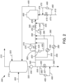
- Fig. 2 illustrates the addition of power recovery turbines in the xylenes fractionation process 300.
- Feed 305 is sent to xylene distillation column 310 where it is separated into overhead stream 315 and bottoms stream 320.
- the bottoms stream 320 is sent through pump 330 before being split into streams 335 and 340.
- a first portion 345 of stream 340 is sent through heat exchanger 350, and a second portion 355 is sent through heat exchanger 360.
- a third portion 420 of stream 340 is sent through power-recovery turbine 425 to recover electric power.
- the remainder 365 of stream 340 is sent through control valve 370.
- Stream 450 from power recovery turbine 425, stream 380 from heat exchanger 350, and stream 385 from heat exchanger 360 are combined with the remainder of 365 to form a combined stream 390.
- a portion, 435, of the combined stream 390 is sent through power-recovery turbine 440 to recover electric power.
- the remainder 453 of combined stream 390 is sent through control valve 395.
- Stream 445 from power-recovery turbine 440 is combined with the remainder 453 to form combined stream 455 which is sent to the xylene column reboiler 400.
- the heated bottoms stream 405 is sent back to the bottom of the xylene distillation column 310.
- a portion 460 of fuel gas stream 410 is sent through power recovery turbine 465 to recover electric power.
- the remainder 475 of 410 is sent to control valve 415.
- the stream 470 from the power recovery turbine 465 and the remainder 475 of fuel gas stream 410 are combined into combined stream 478 and sent to the xylene column reboiler 400.
- a portion 480 of stream 335 is sent through power-recovery turbine 485 to recover electric power.
- the remainder 495 of stream 335 is sent through control valve 337.
- Stream 490 from the power-recovery turbine 485 is combined with the remainder 495 to form stream 500.
- Stream 500 is sent to a heavy aromatics column (not shown) for further processing, for example.
- the power recovered from power recovery turbines 425, 440, 465, 485 can be used to provide power to one or more of the pump 330, or additional electric energy users, such as fans, compressor, and pumps associated with the operation, not shown.
- one or more of the power-recovery turbines 425, 440, 465, 485 can also be used to provide head pressure (increase pressure of the stream), such as pump 330.
- FIGs. 3 and 4 illustrate the incorporation of the present invention into a portion of another process.
- Fig. 3 illustrates a benzene separation process 600 including a benzene column 605.
- the feed stream 610 can be extract from an extractive distillation process or a finishing column overhead stream from an adsorptive separation process, for example.
- the feed stream 610 is sent to heat exchanger 615 where it is preheated before entering the benzene column 605.
- the benzene product stream 620 exits the column and exchanges heats with the feed stream 610 in heat exchanger 615.
- Benzene product stream 620 is further cooled in heat exchanger 625 and sent through control valve 630 to storage (not shown).
- Bottoms stream 635 is sent through control valve 640 for further processing in a toluene column (not shown), for example.
- a reboiler stream 645 exits the column and is sent to the benzene column reboiler 650 for heating.
- An overhead vapor stream 655 from an extract column in an adsorptive separation process, for example, can also be sent to the benzene column reboiler 650.
- a liquid stream 660 from the benzene column reboiler 650 can be sent to an extract column receiver in an adsorptive separation process (not shown).
- Stream 665 exits the benzene column reboiler 650 and is sent to the benzene column 605.
- Stream 670 is sent to a heat exchanger 675 as an auxiliary reboiler and returned to the benzene column 605.
- Steam stream 680 is sent through heat exchanger 675 to heat stream 670. After exiting the heat exchanger 675, the steam stream 680 flows through a control valve 690.
- Benzene column overhead stream 695 is condensed and sent to the benzene column receiver 700.
- Water stream 705 is sent through control valve 710.
- Benzene column condensed overhead stream 715 is split into a first part 720 and a second part 725.
- the first part 720 is sent through control valve 730.
- the second part 725 is sent through control valve 735 and returned to the benzene column 605, as reflux.
- Nitrogen stream 740 is sent through control valve 745 and combined with gas stream 750.
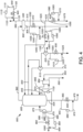
- Fig. 4 illustrates the addition of power recovery turbines in the benzene separation process 800.
- the feed stream 810 is sent to heat exchanger 815 where it is preheated before entering the benzene column 805.
- the benzene product stream 820 exits the column and exchanges heats with the feed stream 810 in heat exchanger 815.
- Benzene product stream 820 is further cooled in heat exchanger 825. Cooled benzene product stream 820 split into first and second portions 1005, 1010.
- First portion 1005 flows through a control valve 830.
- Second portion 1010 is sent through power control turbine 1015.
- Stream 1020 from the power control turbine 1015 is combined with the first portion 1005 to form benzene product stream 1025.
- a first portion 955 of bottoms stream 835 is sent to power recovery turbine 960 to recover power.
- a second portion 965 of bottoms stream 835 is sent through control valve 840.
- the second portion 965 is combined with stream 970 from the power recovery turbine 960 to form combined stream 975 which is sent for further processing in a toluene column (not shown), for example.
- a reboiler stream 845 exits the column and is sent to the benzene column reboiler 850 for heating.
- An overhead vapor stream 855 from an extract column in an adsorptive separation process, for example, can also be sent to the benzene column reboiler 850.
- a liquid stream 860 from the benzene column reboiler 850 can be sent to an extract column receiver in an adsorptive separation process (not shown).
- Stream 865 exits the benzene column reboiler 850 and is sent to the benzene column 805.
- Stream 870 is sent to an auxiliary reboiler 875 after passing through electric heater 1130 and returned to the benzene column 805.
- Steam stream 880 is sent through auxiliary reboiler 875.
- the steam stream 880 is split into first and second portions, 980 and 985.
- First portion 980 flows through a control valve 890.
- Second portion 985 is sent through power control turbine 990.
- Stream 995 from the power control turbine 990 is combined with the first portion 980 to form stream 1000.
- Benzene column overhead stream 895 is condensed and sent to the benzene column receiver 900.
- Water stream 905 is split into first and second portions 1030 and 1035.
- First portion 1030 flows through a control valve 910.
- Second portion 1035 is sent through power control turbine 1040.
- Stream 1045 from the power control turbine 1040 is combined with the first portion 1030 to form water stream 1050.
- Benzene stream 915 is split into a first part 920 and a second part 925.
- the first part 920 is split into first and second portions 1055 and1060.
- First portion 1055 flows through a control valve 930.
- Second portion 1060 is sent through power control turbine 1065.
- Stream 1070 from the power control turbine 1065 is combined with the first portion 1055 to form benzene drag stream 1075.
- the second part 925 is split into first and second portions 1080, 1085.
- First portion 1080 flows through a control valve 935.
- Second portion 1085 is sent through power control turbine 1090.
- Stream 1095 from the power control turbine 1090 is combined with the first portion 1080 to form stream 1100 which is returned to the benzene column 805.
- Nitrogen stream 940 is split into first and second portions 1105 and 1110.
- First portion 1105 flows through a control valve 945.
- Second portion 1110 is sent through power control turbine 1115.
- Stream 1120 from the power control turbine 1115 is combined with the first portion 1105 to form stream 1125 which is combined with gas stream 950.
- An electric heater1130 can be added on stream 870.
- the power recovered from power control turbines 1015, 960, 990, 1090, 1040, 1115, 1065 can be used to reduce the steam requirements for the auxiliary reboiler 875.
- the energy supplied to the electric heater from the power control turbines 1015, 960, 990, 1090, 1040, 1115, 1065 increases the inlet temperature to this reboiler, resulting in less steam needed to provide the desired temperature exiting the auxiliary reboiler, reducing the utility cost to the owner for steam consumption.
- one or more additional power recovery turbines can be added to the process where control valves are in place in order to recover power which can then be sent to one or more pieces of equipment which require power input, such as are described above.
- the devices and processes of the present invention are contemplated as being utilized in a petroleum, petrochemical, or chemical process zone.
- a process control system typically on a computer in a control center.
- the process control system described in connection with the embodiments disclosed herein may be implemented or performed on the computer with a general purpose processor, a digital signal processor (DSP), an application specific integrated circuit (ASIC), a field programmable gate array (FPGA) or other programmable logic device, discrete gate or transistor logic, discrete hardware components, or any combination thereof designed to perform the functions described herein.
- a general-purpose processor may be a microprocessor, or, the processor may be any conventional processor, controller, microcontroller, or state machine.
- a processor may also be a combination of computing devices, e.g., a combination of a DSP and a microprocessor, two or more microprocessors, or any other combination of the foregoing.
- a software module may reside in RAM memory, flash memory, ROM memory, EPROM memory, EEPROM memory, registers, hard disk, a removable disk, a CD-ROM, or any other form of storage medium known in the art.
- An exemplary storage medium is in communication with the processor such the processor reads information from, and writes information to, the storage medium. This includes the storage medium being integral to or with the processor.
- the processor and the storage medium may reside in an ASIC.
- the ASIC may reside in a user terminal.
- the processor and the storage medium may reside as discrete components in a user terminal.
- processors and storage medium or memory are also typically in communication with hardware (e.g., ports, interfaces, antennas, amplifiers, signal processors, etc.) that allow for wired or wireless communication between different components, computers processors, or the like, such as between the input channel, a processor of the control logic, the output channels within the control system and the operator station in the control center.
- hardware e.g., ports, interfaces, antennas, amplifiers, signal processors, etc.
- the transmission of the data or information can be a wireless transmission (for example by Wi-Fi or Bluetooth) or a wired transmission (for example using an Ethernet RJ45 cable or an USB cable).
- a wireless transceiver for example a Wi-Fi transceiver
- the transmission can be performed automatically, at the request of the computers, in response to a request from a computer, or in other ways. Data can be pushed, pulled, fetched, etc., in any combination, or transmitted and received in any other manner.
- the process control system receives information from the power recovery turbines 425, 440, 465, 485 relative to an amount of electricity generated by the power recovery turbines 425, 440, 465, 485. It is contemplated that the power recovery turbines 425, 440, 465, 485 determine (via the processor) the amount of electricity it has generated Alternatively, the process control system receiving the information determines the amount of electricity that has been generated by the power recovery turbines 425, 440, 465, 485. In either configuration, the amount of the electricity generated by the power recovery turbines 425, 440, 465, 485 is displayed on at least one display screen associated with the computer in the control center.
- the process control system receives information associated with the amount of electricity generated by each of the power recovery turbines 425, 440, 465, 485.
- the process control system determines a total electrical power generated based upon the information associated with the each of the power recovery turbines 425, 440, 465, 485 and displays the total electrical power generated on the display screen.
- the total electrical power generated may be displayed instead of, or in conjunction with, the amount of electrical power generated by the individual power recovery turbines 425, 440, 465, 485.
- the electrical energy recovered by the power recovery turbines 425, 440, 465, 485 is often a result of removing energy from the streams that was added to the streams in the petroleum, petrochemical, or chemical process zone.
- the processes according to the present invention provide for the various processing conditions associated with the petroleum, petrochemical, or chemical process zone to be adjusted into order to lower the energy added to the stream(s).
- the parallel control valves installed near each turbine could first be balanced by adjusting each turbine to recover more power while decreasing the flow from the associated control valve to maintain the same flow with higher energy recovery from the turbine.
- the additional power could be stored for future use, directed to the electric heater, 1130, as described or directed to other electrically driven equipment such as cooling fans or pumps, not shown.
- the process control system receives information associated with the throughput of the petroleum, petrochemical, or chemical process zone, and determines a target electrical power generated value for the turbine(s) since the electricity represents energy that is typically added to the overall petroleum, petrochemical, or chemical process zone.
- the determination of the target electrical power generated value may be done when the electricity is at or near a predetermined level. In other words, if the amount of electricity produced meets or exceeds a predetermined level, the process control system can determine one or more processing conditions to adjust and lower the amount of electricity generated until it reaches the target electrical power generated value.
- the process control system will analyze one or more changes to the various processing conditions associated with the petroleum, petrochemical, or chemical process zone to lower the amount of energy recovered by the turbines of the petroleum, petrochemical, or chemical process zone.
- the processing conditions are adjusted without adjusting the throughput of the petroleum, petrochemical, or chemical process zone. This allows for the petroleum, petrochemical, or chemical process zone to have the same throughput, but with a lower operating cost associated with the same throughput.
- the process control software may calculate and display the difference between the target electrical power generated value and the total electrical power generated on the display screen.
- the process control software may recognize that the total electrical power generated exceeds a predetermined level. Accordingly, the process control software may determine the target electrical power generated value. Based upon other data and information received from other sensors and data collection devices typically associated with the petroleum, petrochemical, or chemical process zone, the process control software may determine that the amount of fuel consumed in a piece of equipment can be lowered. While maintaining the throughput of the petroleum, petrochemical, or chemical process zone, the amount of fuel consumed in the piece of equipment is lowered. While this may lower the electricity generated by the turbine, the lower fuel consumption provides a lower operating cost for the same throughput.
- the present invention convert energy that is typically lost into a form that is used elsewhere in the petroleum, petrochemical, or chemical process zone
- the petroleum, petrochemical, or chemical process zone is provided with opportunities to lower the energy input associated with the overall petroleum, petrochemical, or chemical process zone and increase profits by utilizing more energy efficient processes.
Landscapes
- Chemical & Material Sciences (AREA)
- Engineering & Computer Science (AREA)
- Organic Chemistry (AREA)
- Mechanical Engineering (AREA)
- General Engineering & Computer Science (AREA)
- Chemical Kinetics & Catalysis (AREA)
- Water Supply & Treatment (AREA)
- Analytical Chemistry (AREA)
- Oil, Petroleum & Natural Gas (AREA)
- Combustion & Propulsion (AREA)
- Power Engineering (AREA)
- Production Of Liquid Hydrocarbon Mixture For Refining Petroleum (AREA)
- Engine Equipment That Uses Special Cycles (AREA)
- Control Of Turbines (AREA)
Applications Claiming Priority (2)
| Application Number | Priority Date | Filing Date | Title |
|---|---|---|---|
| US15/924,034 US10753235B2 (en) | 2018-03-16 | 2018-03-16 | Use of recovered power in a process |
| PCT/US2019/022424 WO2019178453A1 (en) | 2018-03-16 | 2019-03-15 | Use of recovered power in a process |
Publications (3)
| Publication Number | Publication Date |
|---|---|
| EP3765716A1 EP3765716A1 (en) | 2021-01-20 |
| EP3765716A4 EP3765716A4 (en) | 2022-01-12 |
| EP3765716B1 true EP3765716B1 (en) | 2024-01-17 |
Family
ID=67905241
Family Applications (1)
| Application Number | Title | Priority Date | Filing Date |
|---|---|---|---|
| EP19767446.8A Active EP3765716B1 (en) | 2018-03-16 | 2019-03-15 | Use of recovered power in a process |
Country Status (4)
| Country | Link |
|---|---|
| US (1) | US10753235B2 (ja) |
| EP (1) | EP3765716B1 (ja) |
| JP (1) | JP7141464B2 (ja) |
| WO (1) | WO2019178453A1 (ja) |
Families Citing this family (4)
| Publication number | Priority date | Publication date | Assignee | Title |
|---|---|---|---|---|
| US10508568B2 (en) * | 2018-03-16 | 2019-12-17 | Uop Llc | Process improvement through the addition of power recovery turbine equipment in existing processes |
| US10871085B2 (en) | 2018-03-16 | 2020-12-22 | Uop Llc | Energy-recovery turbines for gas streams |
| US10829698B2 (en) | 2018-03-16 | 2020-11-10 | Uop Llc | Power recovery from quench and dilution vapor streams |
| CN115217531A (zh) * | 2022-06-16 | 2022-10-21 | 宁波科元精化股份有限公司 | 一种平衡重油催化裂解烟机转速的工艺装置及其控制方法 |
Family Cites Families (115)
| Publication number | Priority date | Publication date | Assignee | Title |
|---|---|---|---|---|
| US2276714A (en) * | 1941-06-06 | 1942-03-17 | Louie A Brown | Fluid motor |
| US2436683A (en) * | 1945-04-06 | 1948-02-24 | Atlantic Pipe Line Company | Generator for pipe lines |
| US4455614A (en) | 1973-09-21 | 1984-06-19 | Westinghouse Electric Corp. | Gas turbine and steam turbine combined cycle electric power generating plant having a coordinated and hybridized control system and an improved factory based method for making and testing combined cycle and other power plants and control systems therefor |
| US4037655A (en) * | 1974-04-19 | 1977-07-26 | Electroflood Company | Method for secondary recovery of oil |
| US4057736A (en) * | 1974-09-13 | 1977-11-08 | Jeppson Morris R | Electrical power generation and distribution system |
| US4220009A (en) * | 1977-01-20 | 1980-09-02 | Wenzel Joachim O M | Power station |
| US4369373A (en) * | 1977-09-06 | 1983-01-18 | Wiseman Ben W | Method and apparatus for generating electricity from the flow of fluid through a well |
| FR2414162A1 (fr) | 1978-01-09 | 1979-08-03 | Lenz Karl | Procede et agencement pour commander, surveiller et mesurer le debit d'un clapet de passage de fluide |
| US4285481A (en) | 1979-06-04 | 1981-08-25 | Biscomb Lloyd I | Multiple wind turbine tethered airfoil wind energy conversion system |
| US4496845A (en) * | 1982-12-27 | 1985-01-29 | Cla-Val Co. | Method and apparatus for control of a turbine generator |
| US4654537A (en) | 1985-01-24 | 1987-03-31 | Baker Cac | Flowline power generator |
| CA1310682C (en) * | 1988-09-27 | 1992-11-24 | Kwc Ag | Water fitting, particularly for sanitary domestic installations |
| US5209634A (en) * | 1991-02-20 | 1993-05-11 | Owczarek Jerzy A | Adjustable guide vane assembly for the exhaust flow passage of a steam turbine |
| JP3010779B2 (ja) * | 1991-04-24 | 2000-02-21 | 東ソー株式会社 | ベンゼンの蒸留方法 |
| JPH0579718A (ja) * | 1991-09-20 | 1993-03-30 | Hitachi Ltd | ヘリウム液化冷凍装置 |
| EP0552039A1 (en) | 1992-01-17 | 1993-07-21 | Gec-Marconi Limited | Transmitter tuning |
| DE9215695U1 (de) * | 1992-11-18 | 1993-10-14 | Leverkusen Energieversorgung | Erdgas-Expansionsanlage |
| DE9215696U1 (de) | 1992-11-18 | 1994-03-17 | Piller Gmbh Co Kg Anton | Stromgewinnungsanlage |
| RU94026102A (ru) * | 1993-07-22 | 1996-06-10 | Ормат Индастриз Лтд. (Il) | Регенерирующая энергию система уменьшения давления и способ ее применения |
| US5606858A (en) * | 1993-07-22 | 1997-03-04 | Ormat Industries, Ltd. | Energy recovery, pressure reducing system and method for using the same |
| US5384489A (en) | 1994-02-07 | 1995-01-24 | Bellac; Alphonse H. | Wind-powered electricity generating system including wind energy storage |
| US6216463B1 (en) * | 1995-10-19 | 2001-04-17 | Leonard Leroux Stewart | Method of combining waste water treatment and power generation technologies |
| FR2745436B1 (fr) * | 1996-02-28 | 1998-04-03 | Elf Aquitaine | Generateur d'energie electrique en ligne autonome |
| WO2004084371A1 (ja) | 1998-08-31 | 2004-09-30 | Kaoru Fujita | 発電プラントの最適化制御方法及び最適化制御装置 |
| WO2000036268A1 (en) * | 1998-12-15 | 2000-06-22 | Alliedsignal Inc. | A fluid-driven alternator having an internal impeller |
| US6265453B1 (en) | 1999-07-01 | 2001-07-24 | Syntroleum Corporation | Hydrocarbon conversion system with enhanced combustor and method |
| US6354084B1 (en) | 1999-08-20 | 2002-03-12 | Cummins Engine Company, Inc. | Exhaust gas recirculation system for a turbocharged internal combustion engine |
| JP3299531B2 (ja) | 1999-12-22 | 2002-07-08 | 川崎重工業株式会社 | 発電プラント |
| DE102009031557A1 (de) | 2009-03-02 | 2010-09-09 | Sms Siemag Ag | Energierückgewinnung in Warmbandstraßen durch Umwandlung der Kühlwärme der Stranggießanlage sowie der Restwärme von Brammen und Coils in elektrische Energie oder sonstige Nutzung der aufgefangenen Prozesswärme |
| US7062359B2 (en) | 2000-12-29 | 2006-06-13 | Abb Ab | Substation control system |
| US6554074B2 (en) * | 2001-03-05 | 2003-04-29 | Halliburton Energy Services, Inc. | Lift fluid driven downhole electrical generator and method for use of the same |
| ATE361531T1 (de) | 2001-03-30 | 2007-05-15 | Pebble Bed Modular Reactor Pty | Kernreaktoranlage und verfahren zum konditionieren deren stromerzeugungskreis |
| GB0111124D0 (en) * | 2001-05-05 | 2001-06-27 | Spring Gregson W M | Torque-generating apparatus |
| US20040131138A1 (en) | 2001-05-25 | 2004-07-08 | Michael Correia | Brayton cycle nuclear power plant and a method of starting the brayton cycle |
| US20080017369A1 (en) * | 2002-07-18 | 2008-01-24 | Sarada Steven A | Method and apparatus for generating pollution free electrical energy from hydrocarbons |
| US6820689B2 (en) * | 2002-07-18 | 2004-11-23 | Production Resources, Inc. | Method and apparatus for generating pollution free electrical energy from hydrocarbons |
| US20040085046A1 (en) | 2002-11-01 | 2004-05-06 | General Electric Company | Power conditioning system for turbine motor/generator |
| US6898540B2 (en) | 2002-11-12 | 2005-05-24 | General Electric Company | System and method for displaying real-time turbine corrected output and heat rate |
| US6824347B2 (en) * | 2002-12-30 | 2004-11-30 | Michael A. Maloney | Valve and related methods for reducing fluid pressure and generating power |
| US7280435B2 (en) | 2003-03-06 | 2007-10-09 | General Electric Company | Switching circuitry for reconfigurable arrays of sensor elements |
| CA2512741A1 (en) | 2003-03-31 | 2004-10-14 | Mayekawa Mfg. Co., Ltd. | Coal energy utilization system by superconducting power transmission |
| US7002261B2 (en) * | 2003-07-15 | 2006-02-21 | Conocophillips Company | Downhole electrical submersible power generator |
| US6938425B2 (en) | 2003-08-11 | 2005-09-06 | Siemens Westinghouse Power Corporation | System and method for controlling water injection in a turbine engine |
| WO2005041396A2 (en) * | 2003-10-22 | 2005-05-06 | Scherzer Paul L | Method and system for generating electricity utilizing naturally occurring gas |
| US7021126B1 (en) | 2004-09-15 | 2006-04-04 | General Electric Company | Methods for low-cost estimation of steam turbine performance |
| JP2006205135A (ja) | 2005-01-31 | 2006-08-10 | Mitsubishi Heavy Ind Ltd | 複合廃棄物処理システム |
| US7357599B2 (en) * | 2005-08-10 | 2008-04-15 | Criptonic Energy Solutions, Inc. | Waste water electrical power generating system |
| US7948101B2 (en) | 2005-09-02 | 2011-05-24 | John Christopher Burtch | Apparatus for production of hydrogen gas using wind and wave action |
| CA2627859A1 (en) | 2005-10-31 | 2007-05-10 | Chapdrive As | A turbine driven electric power production system and a method for control thereof |
| US7757493B2 (en) | 2006-03-07 | 2010-07-20 | Uop Llc | Fluid catalytic cracking steam pressure letdown power recovery system and process |
| US7501712B2 (en) * | 2006-03-10 | 2009-03-10 | David Bolyard | Process for using waste water from community sewer systems to generate electrical power |
| RS20060186A (en) | 2006-03-16 | 2006-12-15 | Stojanović, Miljan | Pipe for tranforming energy of fluid flows into electric energy |
| CN101512448B (zh) | 2006-06-23 | 2012-11-14 | 沙特阿拉伯石油公司 | 能量回收系统中用于目标确定以及最优驱动力分布的系统、方法 |
| US7958716B2 (en) * | 2007-03-30 | 2011-06-14 | Ziegenfuss Mark R | Gas production well secondary purpose turbine electric power generator system |
| US8067852B2 (en) * | 2007-03-31 | 2011-11-29 | Mdl Enterprises, Llc | Fluid driven electric power generation system |
| US7579703B2 (en) * | 2007-05-24 | 2009-08-25 | Joseph Salvatore Shifrin | Hydroelectric in-pipe generator |
| US8612029B2 (en) | 2007-06-15 | 2013-12-17 | Shell Oil Company | Framework and method for monitoring equipment |
| US8092675B2 (en) * | 2007-10-08 | 2012-01-10 | Zodiac Group Australia Pty. Ltd. | Energy generation methods and systems for swimming pools and other vessels with recirculating fluid |
| US7632040B2 (en) * | 2007-10-30 | 2009-12-15 | Criptonic Energy Solutions, Inc. | Waste water electrical power generating system with storage system and methods for use therewith |
| WO2009062103A1 (en) | 2007-11-09 | 2009-05-14 | Markron Technologies, Llc | Solar thermal hybridization of a fossil fired rankine cycle |
| EP2235329A4 (en) | 2007-12-20 | 2018-02-21 | GKN Aerospace Sweden AB | Gas turbine engine |
| US8067850B2 (en) * | 2008-01-15 | 2011-11-29 | Techstream Control Systems Inc | Method for creating a low fluid pressure differential electrical generating system |
| US7768146B2 (en) * | 2008-03-21 | 2010-08-03 | Alfiero Balzano | Flow generator for use in connection with a utility conduit |
| EP2310965B1 (en) | 2008-06-06 | 2017-08-23 | Saudi Arabian Oil Company | System and related methods for global targeting of process utilities under varying conditions |
| US7975490B2 (en) * | 2008-07-28 | 2011-07-12 | General Electric Company | Method and systems for operating a combined cycle power plant |
| US8069672B2 (en) * | 2008-12-22 | 2011-12-06 | General Electric Company | Method and systems for operating a combined cycle power plant |
| US8294292B2 (en) * | 2009-04-22 | 2012-10-23 | Rain Bird Corporation | Power supply system |
| EP2301886A1 (en) | 2009-09-03 | 2011-03-30 | Ammonia Casale S.A. | Waste heat recovery in a chemical process and plant, particularly for the synthesis of ammonia |
| US8680704B1 (en) * | 2009-09-18 | 2014-03-25 | Taylor Valve Technology, Inc. | Wellhead pressure reduction and electrical power generation |
| US8404918B2 (en) | 2009-09-28 | 2013-03-26 | Uop Llc | Energy efficiency in adsorptive separation |
| WO2011053925A2 (en) | 2009-10-30 | 2011-05-05 | Qgen Ltd. | Control and solar power improvements of a concentrated solar power-enabled power plant |
| WO2011066823A2 (de) | 2009-12-05 | 2011-06-09 | Jens Mehnert | Verfahren und vorrichtung zur analyse des energieeinsatzes beim betrieb eines produktionssystems |
| US8967590B2 (en) | 2010-03-02 | 2015-03-03 | Westlock Controls Corporation | Micro-power generator for valve control applications |
| ITPI20100038A1 (it) | 2010-03-29 | 2011-09-30 | Sime S R L | Metodo e apparato per l'addolcimento e la disidratazione di un gas a base di idrocarburi |
| FR2966814B1 (fr) | 2010-10-28 | 2016-01-01 | IFP Energies Nouvelles | Procede de production d'hydrogene par vaporeformage d'une coupe petroliere avec production de vapeur optimisee. |
| CN102570868B (zh) | 2010-12-22 | 2015-04-01 | 通用电气公司 | 电力转换系统和方法 |
| US20120227440A1 (en) | 2011-03-10 | 2012-09-13 | Alstom Technology Ltd. | System And Process For The Physical Absorption of Carbon Dioxide From a Flue Gas Stream |
| TWI563165B (en) | 2011-03-22 | 2016-12-21 | Exxonmobil Upstream Res Co | Power generation system and method for generating power |
| US8946921B2 (en) * | 2011-04-12 | 2015-02-03 | Plexaire, Llc | Pressure powered impeller system and related method of use |
| US9222410B2 (en) | 2011-04-13 | 2015-12-29 | General Electric Company | Power plant |
| CA2780451A1 (en) * | 2011-06-21 | 2012-12-21 | Genalta Power, Inc. | Variable speed power generation from industrial fluid energy sources |
| EP2562423A1 (en) * | 2011-08-25 | 2013-02-27 | Vetco Gray Controls Limited | Rotors |
| US9085499B2 (en) | 2011-11-09 | 2015-07-21 | Uop Llc | Energy efficiency in adsorptive separation |
| US8997490B2 (en) | 2012-02-02 | 2015-04-07 | Electratherm, Inc. | Heat utilization in ORC systems |
| GB2499991A (en) | 2012-03-05 | 2013-09-11 | Solaredge Technologies Ltd | DC link circuit for photovoltaic array |
| US8888990B2 (en) | 2012-03-29 | 2014-11-18 | Uop Llc | Process and apparatus for producing diesel from a hydrocarbon stream |
| US10260415B2 (en) | 2012-08-22 | 2019-04-16 | Hi Eff Utility Rescue LLC | High efficiency power generation system and system upgrades |
| KR20150122665A (ko) | 2013-01-28 | 2015-11-02 | 에코진 파워 시스템스, 엘엘씨 | 초임계 이산화탄소 랭킨 사이클 중에 동력 터빈 스로틀 밸브를 제어하기 위한 프로세스 |
| JP2016056808A (ja) | 2013-01-29 | 2016-04-21 | 日立建機株式会社 | 作業機械の圧油エネルギ回収装置 |
| JP6010489B2 (ja) | 2013-03-12 | 2016-10-19 | 三菱日立パワーシステムズ株式会社 | 熱電可変型コジェネレーションシステム |
| US8763625B1 (en) | 2013-04-12 | 2014-07-01 | John T. Carter | Siphon pump technology and apparatuses |
| JP5790952B2 (ja) | 2013-04-23 | 2015-10-07 | 横河電機株式会社 | 生産エネルギー管理システムおよびコンピュータプログラム |
| WO2014178079A2 (en) | 2013-04-26 | 2014-11-06 | Eesavyasa Technologies Pvt. Ltd | Led lighting systems using compressed air based power generation and a method thereof |
| US9677015B2 (en) | 2013-06-20 | 2017-06-13 | Exxonmobil Research And Engineering Company | Staged solvent assisted hydroprocessing and resid hydroconversion |
| CN104463341B (zh) | 2013-09-25 | 2017-10-27 | 北京宜能高科科技有限公司 | 图表化的蒸汽动力系统分析优化方法和装置 |
| US9764272B2 (en) | 2013-10-28 | 2017-09-19 | Energy Recovery, Inc. | Systems and methods for utilizing turbine systems within gas processing systems |
| US20160252015A1 (en) | 2013-11-27 | 2016-09-01 | Hitachi, Ltd. | Gas Turbine Corresponding to Renewable Energy and Control Method Therefor |
| RU2570131C2 (ru) | 2014-04-09 | 2015-12-10 | Федеральное государственное бюджетное образовательное учреждение высшего профессионального образования "Казанский государственный энергетический университет" (ФГБОУ ВПО "КГЭУ") | Способ работы тепловой электрической станции |
| US9863396B2 (en) * | 2014-06-16 | 2018-01-09 | Gary Joseph Oncale | Systems and methods for generating energy |
| JP6389284B2 (ja) | 2014-06-30 | 2018-09-12 | エクソンモービル・ケミカル・パテンツ・インク | パラキシレンの製造方法 |
| WO2016053780A1 (en) | 2014-09-29 | 2016-04-07 | Uop Llc | Methods for reducing flue gas emissions from fluid catalytic cracking unit regenerators |
| US20160141878A1 (en) | 2014-11-05 | 2016-05-19 | John Anton Johansen | Dc appliance system |
| US9803561B2 (en) | 2014-11-18 | 2017-10-31 | General Electric Company | Power output and emissions based degraded gas turbine tuning and control systems, computer program products and related methods |
| US10088507B2 (en) | 2014-12-03 | 2018-10-02 | Saudi Arabian Oil Company | Energy performance metric in hydrocarbon-producing facilities |
| WO2016097855A1 (en) | 2014-12-17 | 2016-06-23 | King Abdullah University Of Science And Technology | Xylene isomerization |
| US11060032B2 (en) | 2015-01-02 | 2021-07-13 | Suncoke Technology And Development Llc | Integrated coke plant automation and optimization using advanced control and optimization techniques |
| CN107735935A (zh) | 2015-05-06 | 2018-02-23 | 维斯塔斯风力系统集团公司 | 风力涡轮机发电系统 |
| US9803145B2 (en) | 2015-08-24 | 2017-10-31 | Saudi Arabian Oil Company | Power generation from waste heat in integrated crude oil refining, aromatics, and utilities facilities |
| CA3006536A1 (en) | 2015-11-24 | 2017-06-01 | New Energy Corporation Inc. | Mobile electric power generating and conditioning system |
| CA2964126C (en) * | 2016-04-12 | 2019-01-08 | Airtek Systems Inc. | System and method for generating rotational power |
| US10301551B2 (en) | 2016-06-30 | 2019-05-28 | Uop Llc | Modular crude refining process |
| CN206538206U (zh) | 2016-11-29 | 2017-10-03 | 江苏悦达家纺有限公司 | 一种可优化水质的热回收装置 |
| US10508568B2 (en) * | 2018-03-16 | 2019-12-17 | Uop Llc | Process improvement through the addition of power recovery turbine equipment in existing processes |
| US10811884B2 (en) * | 2018-03-16 | 2020-10-20 | Uop Llc | Consolidation and use of power recovered from a turbine in a process unit |
| US11507031B2 (en) * | 2018-03-16 | 2022-11-22 | Uop Llc | Recovered electric power measuring system and method for collecting data from a recovered electric power measuring system |
-
2018
- 2018-03-16 US US15/924,034 patent/US10753235B2/en active Active
-
2019
- 2019-03-15 WO PCT/US2019/022424 patent/WO2019178453A1/en active Application Filing
- 2019-03-15 EP EP19767446.8A patent/EP3765716B1/en active Active
- 2019-03-15 JP JP2020547141A patent/JP7141464B2/ja active Active
Also Published As
| Publication number | Publication date |
|---|---|
| WO2019178453A1 (en) | 2019-09-19 |
| EP3765716A4 (en) | 2022-01-12 |
| JP2021516742A (ja) | 2021-07-08 |
| EP3765716A1 (en) | 2021-01-20 |
| US20190284966A1 (en) | 2019-09-19 |
| JP7141464B2 (ja) | 2022-09-22 |
| US10753235B2 (en) | 2020-08-25 |
Similar Documents
| Publication | Publication Date | Title |
|---|---|---|
| EP3765716B1 (en) | Use of recovered power in a process | |
| EP3766168B1 (en) | Process improvement through the addition of power recovery turbine equipment in existing processes | |
| EP3765583B1 (en) | Hydroprocessing unit with power recovery turbines | |
| EP3765717B1 (en) | Consolidation and use of power recovered from a turbine in a process unit | |
| JP2008533287A (ja) | 合成炭化水素化合物を生成するためのシステム、方法、および組成物 | |
| US20190284961A1 (en) | Steam reboiler with turbine | |
| EP3765171B1 (en) | Turbine with supersonic separation | |
| US11713697B2 (en) | Energy-recovery turbines for gas streams | |
| CN104159820A (zh) | 船舶的废热回收系统 | |
| CN102985145A (zh) | 蒸馏方法和多塔热集成蒸馏系统 | |
| EP3765718B1 (en) | Processes for adjusting condition of a chemical processing unit with a turbine | |
| Liu et al. | Local heat exchanger network optimization of industrial coal-to-olefin process based on hot direct feed/discharge strategy | |
| CN110998199A (zh) | 在芳烃联合装置中使用废热流的方法和装置 | |
| Labarta et al. | A hybrid simulation-optimization approach for the design of internally heat-integrated distillation columns |
Legal Events
| Date | Code | Title | Description |
|---|---|---|---|
| STAA | Information on the status of an ep patent application or granted ep patent |
Free format text: STATUS: THE INTERNATIONAL PUBLICATION HAS BEEN MADE |
|
| PUAI | Public reference made under article 153(3) epc to a published international application that has entered the european phase |
Free format text: ORIGINAL CODE: 0009012 |
|
| STAA | Information on the status of an ep patent application or granted ep patent |
Free format text: STATUS: REQUEST FOR EXAMINATION WAS MADE |
|
| 17P | Request for examination filed |
Effective date: 20200922 |
|
| AK | Designated contracting states |
Kind code of ref document: A1 Designated state(s): AL AT BE BG CH CY CZ DE DK EE ES FI FR GB GR HR HU IE IS IT LI LT LU LV MC MK MT NL NO PL PT RO RS SE SI SK SM TR |
|
| AX | Request for extension of the european patent |
Extension state: BA ME |
|
| DAV | Request for validation of the european patent (deleted) | ||
| DAX | Request for extension of the european patent (deleted) | ||
| A4 | Supplementary search report drawn up and despatched |
Effective date: 20211209 |
|
| RIC1 | Information provided on ipc code assigned before grant |
Ipc: F01D 17/06 20060101ALI20211203BHEP Ipc: F01D 17/10 20060101ALI20211203BHEP Ipc: F01D 15/10 20060101AFI20211203BHEP |
|
| P01 | Opt-out of the competence of the unified patent court (upc) registered |
Effective date: 20230421 |
|
| GRAP | Despatch of communication of intention to grant a patent |
Free format text: ORIGINAL CODE: EPIDOSNIGR1 |
|
| STAA | Information on the status of an ep patent application or granted ep patent |
Free format text: STATUS: GRANT OF PATENT IS INTENDED |
|
| INTG | Intention to grant announced |
Effective date: 20230912 |
|
| GRAS | Grant fee paid |
Free format text: ORIGINAL CODE: EPIDOSNIGR3 |
|
| GRAA | (expected) grant |
Free format text: ORIGINAL CODE: 0009210 |
|
| STAA | Information on the status of an ep patent application or granted ep patent |
Free format text: STATUS: THE PATENT HAS BEEN GRANTED |
|
| AK | Designated contracting states |
Kind code of ref document: B1 Designated state(s): AL AT BE BG CH CY CZ DE DK EE ES FI FR GB GR HR HU IE IS IT LI LT LU LV MC MK MT NL NO PL PT RO RS SE SI SK SM TR |
|
| REG | Reference to a national code |
Ref country code: GB Ref legal event code: FG4D |
|
| REG | Reference to a national code |
Ref country code: CH Ref legal event code: EP |
|
| REG | Reference to a national code |
Ref country code: DE Ref legal event code: R096 Ref document number: 602019045249 Country of ref document: DE |
|
| REG | Reference to a national code |
Ref country code: IE Ref legal event code: FG4D |
|
| PGFP | Annual fee paid to national office [announced via postgrant information from national office to epo] |
Ref country code: DE Payment date: 20240328 Year of fee payment: 6 |
|
| REG | Reference to a national code |
Ref country code: LT Ref legal event code: MG9D |
|
| REG | Reference to a national code |
Ref country code: NL Ref legal event code: MP Effective date: 20240117 |