EP3765171B1 - Turbine with supersonic separation - Google Patents
Turbine with supersonic separation Download PDFInfo
- Publication number
- EP3765171B1 EP3765171B1 EP19767007.8A EP19767007A EP3765171B1 EP 3765171 B1 EP3765171 B1 EP 3765171B1 EP 19767007 A EP19767007 A EP 19767007A EP 3765171 B1 EP3765171 B1 EP 3765171B1
- Authority
- EP
- European Patent Office
- Prior art keywords
- vapor stream
- turbine
- stream
- processing unit
- outlet
- Prior art date
- Legal status (The legal status is an assumption and is not a legal conclusion. Google has not performed a legal analysis and makes no representation as to the accuracy of the status listed.)
- Active
Links
- 238000000926 separation method Methods 0.000 title claims description 15
- 238000012545 processing Methods 0.000 claims description 40
- 238000000034 method Methods 0.000 claims description 37
- 230000008569 process Effects 0.000 claims description 36
- 230000005611 electricity Effects 0.000 claims description 25
- UFHFLCQGNIYNRP-UHFFFAOYSA-N Hydrogen Chemical compound [H][H] UFHFLCQGNIYNRP-UHFFFAOYSA-N 0.000 claims description 21
- 229910052739 hydrogen Inorganic materials 0.000 claims description 20
- 239000001257 hydrogen Substances 0.000 claims description 20
- 229930195733 hydrocarbon Natural products 0.000 claims description 10
- 150000002430 hydrocarbons Chemical class 0.000 claims description 10
- 239000007788 liquid Substances 0.000 claims description 9
- 238000010791 quenching Methods 0.000 description 10
- 239000007789 gas Substances 0.000 description 8
- 238000004886 process control Methods 0.000 description 8
- 238000004891 communication Methods 0.000 description 7
- 238000011084 recovery Methods 0.000 description 7
- 238000004804 winding Methods 0.000 description 6
- 230000005540 biological transmission Effects 0.000 description 5
- 239000012071 phase Substances 0.000 description 5
- 230000009467 reduction Effects 0.000 description 5
- 238000006243 chemical reaction Methods 0.000 description 4
- 150000001875 compounds Chemical class 0.000 description 4
- 238000013461 design Methods 0.000 description 4
- 238000007670 refining Methods 0.000 description 4
- 239000000126 substance Substances 0.000 description 4
- 239000004215 Carbon black (E152) Substances 0.000 description 3
- 230000006870 function Effects 0.000 description 3
- 230000004044 response Effects 0.000 description 3
- 238000011144 upstream manufacturing Methods 0.000 description 3
- XLYOFNOQVPJJNP-UHFFFAOYSA-N water Substances O XLYOFNOQVPJJNP-UHFFFAOYSA-N 0.000 description 3
- 229910001868 water Inorganic materials 0.000 description 3
- QGZKDVFQNNGYKY-UHFFFAOYSA-N Ammonia Chemical compound N QGZKDVFQNNGYKY-UHFFFAOYSA-N 0.000 description 2
- RWSOTUBLDIXVET-UHFFFAOYSA-N Dihydrogen sulfide Chemical compound S RWSOTUBLDIXVET-UHFFFAOYSA-N 0.000 description 2
- 230000008901 benefit Effects 0.000 description 2
- 238000012993 chemical processing Methods 0.000 description 2
- 230000001276 controlling effect Effects 0.000 description 2
- 229910000037 hydrogen sulfide Inorganic materials 0.000 description 2
- 238000012986 modification Methods 0.000 description 2
- 230000004048 modification Effects 0.000 description 2
- 238000004088 simulation Methods 0.000 description 2
- 150000001412 amines Chemical class 0.000 description 1
- 229910021529 ammonia Inorganic materials 0.000 description 1
- 125000004432 carbon atom Chemical group C* 0.000 description 1
- 230000008859 change Effects 0.000 description 1
- 238000001816 cooling Methods 0.000 description 1
- 238000013480 data collection Methods 0.000 description 1
- 238000011161 development Methods 0.000 description 1
- 238000005265 energy consumption Methods 0.000 description 1
- 238000005516 engineering process Methods 0.000 description 1
- 239000012530 fluid Substances 0.000 description 1
- 238000005194 fractionation Methods 0.000 description 1
- 230000021715 photosynthesis, light harvesting Effects 0.000 description 1
- 238000010248 power generation Methods 0.000 description 1
- 238000003672 processing method Methods 0.000 description 1
- 230000001105 regulatory effect Effects 0.000 description 1
- 150000003839 salts Chemical class 0.000 description 1
- 238000012546 transfer Methods 0.000 description 1
- 239000012808 vapor phase Substances 0.000 description 1
- 239000002918 waste heat Substances 0.000 description 1
Images

Classifications
-
- F—MECHANICAL ENGINEERING; LIGHTING; HEATING; WEAPONS; BLASTING
- F01—MACHINES OR ENGINES IN GENERAL; ENGINE PLANTS IN GENERAL; STEAM ENGINES
- F01D—NON-POSITIVE DISPLACEMENT MACHINES OR ENGINES, e.g. STEAM TURBINES
- F01D25/00—Component parts, details, or accessories, not provided for in, or of interest apart from, other groups
- F01D25/32—Collecting of condensation water; Drainage ; Removing solid particles
-
- F—MECHANICAL ENGINEERING; LIGHTING; HEATING; WEAPONS; BLASTING
- F01—MACHINES OR ENGINES IN GENERAL; ENGINE PLANTS IN GENERAL; STEAM ENGINES
- F01K—STEAM ENGINE PLANTS; STEAM ACCUMULATORS; ENGINE PLANTS NOT OTHERWISE PROVIDED FOR; ENGINES USING SPECIAL WORKING FLUIDS OR CYCLES
- F01K17/00—Using steam or condensate extracted or exhausted from steam engine plant
- F01K17/02—Using steam or condensate extracted or exhausted from steam engine plant for heating purposes, e.g. industrial, domestic
-
- B—PERFORMING OPERATIONS; TRANSPORTING
- B01—PHYSICAL OR CHEMICAL PROCESSES OR APPARATUS IN GENERAL
- B01D—SEPARATION
- B01D5/00—Condensation of vapours; Recovering volatile solvents by condensation
- B01D5/0057—Condensation of vapours; Recovering volatile solvents by condensation in combination with other processes
-
- F—MECHANICAL ENGINEERING; LIGHTING; HEATING; WEAPONS; BLASTING
- F01—MACHINES OR ENGINES IN GENERAL; ENGINE PLANTS IN GENERAL; STEAM ENGINES
- F01D—NON-POSITIVE DISPLACEMENT MACHINES OR ENGINES, e.g. STEAM TURBINES
- F01D15/00—Adaptations of machines or engines for special use; Combinations of engines with devices driven thereby
- F01D15/10—Adaptations for driving, or combinations with, electric generators
-
- F—MECHANICAL ENGINEERING; LIGHTING; HEATING; WEAPONS; BLASTING
- F05—INDEXING SCHEMES RELATING TO ENGINES OR PUMPS IN VARIOUS SUBCLASSES OF CLASSES F01-F04
- F05D—INDEXING SCHEME FOR ASPECTS RELATING TO NON-POSITIVE-DISPLACEMENT MACHINES OR ENGINES, GAS-TURBINES OR JET-PROPULSION PLANTS
- F05D2220/00—Application
- F05D2220/30—Application in turbines
- F05D2220/31—Application in turbines in steam turbines
-
- F—MECHANICAL ENGINEERING; LIGHTING; HEATING; WEAPONS; BLASTING
- F05—INDEXING SCHEMES RELATING TO ENGINES OR PUMPS IN VARIOUS SUBCLASSES OF CLASSES F01-F04
- F05D—INDEXING SCHEME FOR ASPECTS RELATING TO NON-POSITIVE-DISPLACEMENT MACHINES OR ENGINES, GAS-TURBINES OR JET-PROPULSION PLANTS
- F05D2220/00—Application
- F05D2220/60—Application making use of surplus or waste energy
- F05D2220/62—Application making use of surplus or waste energy with energy recovery turbines
-
- F—MECHANICAL ENGINEERING; LIGHTING; HEATING; WEAPONS; BLASTING
- F05—INDEXING SCHEMES RELATING TO ENGINES OR PUMPS IN VARIOUS SUBCLASSES OF CLASSES F01-F04
- F05D—INDEXING SCHEME FOR ASPECTS RELATING TO NON-POSITIVE-DISPLACEMENT MACHINES OR ENGINES, GAS-TURBINES OR JET-PROPULSION PLANTS
- F05D2220/00—Application
- F05D2220/70—Application in combination with
- F05D2220/76—Application in combination with an electrical generator
-
- F—MECHANICAL ENGINEERING; LIGHTING; HEATING; WEAPONS; BLASTING
- F05—INDEXING SCHEMES RELATING TO ENGINES OR PUMPS IN VARIOUS SUBCLASSES OF CLASSES F01-F04
- F05D—INDEXING SCHEME FOR ASPECTS RELATING TO NON-POSITIVE-DISPLACEMENT MACHINES OR ENGINES, GAS-TURBINES OR JET-PROPULSION PLANTS
- F05D2260/00—Function
- F05D2260/14—Preswirling
-
- F—MECHANICAL ENGINEERING; LIGHTING; HEATING; WEAPONS; BLASTING
- F22—STEAM GENERATION
- F22B—METHODS OF STEAM GENERATION; STEAM BOILERS
- F22B37/00—Component parts or details of steam boilers
- F22B37/02—Component parts or details of steam boilers applicable to more than one kind or type of steam boiler
- F22B37/26—Steam-separating arrangements
- F22B37/32—Steam-separating arrangements using centrifugal force
Definitions
- This invention relates generally to a turbine used in vapor stream in a chemical processing or refining plant, and more particularly to a turbine used with a vapor stream that is at or near its dew point.
- Control valves are used to control the flow, upstream or downstream pressure, temperatures, or levels, etc.
- mechanical energy is dissipated. Since the energy is dissipated, without recovery, the energy is lost.
- the lost energy is often associated with energy added to the system.
- refiners and processors often operate the processing/refining unit with this inefficiency to maintain throughput of the processing/refining unit at minimal investment and operating complexity. Nevertheless, this inefficiency is an opportunity for processors to lower operating costs and, thus increase profits.
- the turbine could potentially be problematic. Specifically, in a vapor stream at or near its dew point, when the vapor stream passes through the turbine and its pressure is reduced, the resultant vapor stream will partially condense forming a two-phase stream as a result of the cooling of expansion of the vapor. While there are currently turbines that are designed to accommodate the two-phase stream, such turbines are complicated in design and difficult to predict in operation.
- the present invention attempts to overcome one or more shortcomings discussed above.
- upstream of the turbine is a supersonic separator which separates out the heavier components before the vapor stream is passed to the turbine.
- the supersonic separator imparts a swirl at sonic or supersonic velocity to the vapor which condenses some of the heavier compounds into droplets.
- the droplets are separated from the remaining vapor phase components which are then passed to the turbine for a pressure reduction while generating electricity.
- the turbine is able to provide information about the amount of energy removed. This information may be utilized to in determining adjustments for various processing conditions which reduce the amount of energy added to the process. This permits the processor to more efficiently operate the processing unit without reducing the throughput of the processing unit.
- the present invention provides an apparatus for generating electricity which includes: a body containing a supersonic separation device with with an inlet configured to receive a vapor stream, a first outlet for a superheated vapor stream and, a second outlet for a liquid stream; a baffle disposed within the body and configured to impart a swirl at or above sonic velocity to the vapor stream; an internal cavity in the body between the inlet, the first outlet, and the second outlet.
- the apparatus further comprises a turbine having a turbine wheel configured to transmit rotational movement from the superheated vapor stream to an electrical generator, the turbine wheel disposed between the outlet and the internal cavity.
- the present invention provides also a process for recovering power from a vapor stream using the above-mentioned apparatus, the process comprising: condensing a portion of the vapor stream in the supersonic separation device, the supersonic separation device configured to impart a swirl at or above a sonic velocity on the vapor stream passing therethrough; separating the liquid stream condensed portion from the vapor stream with the supersonic separation device to provide the superheated vapor stream; and recovering power from the superheated vapor stream in the turbine, the turbine comprising the turbine wheel configured to transmit rotational movement to the electrical generator.
- the present invention provides a supersonic separating device upstream of a turbine.
- the supersonic separating device condenses a portion of a vapor stream that is at or near its due point.
- the remaining vapor portion, a superheated stream as a result of the heavier compounds being removed, is passed through the turbine, allowing the pressure to be reduced.
- the turbine generates electricity from this energy dissipation which is recovered or used elsewhere in the processing unit.
- the reduced pressure vapor stream is less likely to be a two-phase system and can be used as desired in the process unit.
- FIG. 1 An exemplary device 10 according to the present invention is shown in Figure 1 .
- the device 10 is used for generating electricity and a vapor stream with a lower pressure.
- the device 10 includes a supersonic separator 12 and a turbine 14. It is contemplated that the supersonic separator 12 and the turbine 14 are integrally formed as a single unit, i.e., the two are contained within a single body 15 (or housing) and are not connected to each other with any external conduits. This is merely a preferred configuration, and it is contemplated that the advantages and benefits of the present invention are achieved with the supersonic separator 12 and the turbine 14 being discrete components as opposed to a single unit.
- the particular configuration of the supersonic separator 12 is not necessarily important for the practicing of the present invention.
- Exemplary supersonic separators 12 are disclosed in U.S. Pat. Nos. 6,280,502 , which discloses an apparatus having the features specified in the preamble of claim 1, 6,962,199, 7,261,766, 7,318,849, 7,494,535, 8,257,458, 8,398,734, 7,909,912, 8,475,555, 8,657,930, and 9,034, 082.
- the supersonic separator 12 comprises an inlet 16 configured to receive a vapor stream 18, a first outlet 19 for a superheated vapor stream 20 and, a second outlet 22 for a liquid stream 24.
- the vapor stream 18 is at or near its dew point.
- the vapor stream 18 could be within 10 °C of a dew point of the vapor stream 18, within 5 °C of a dew point of the vapor stream 18, within 1 °C of a dew point of the vapor stream 18, or greater than the dew point of the vapor stream 18 but less than 1 °C from the dew point of the vapor stream 18.
- the vapor stream 18 includes hydrogen gas and light hydrocarbons, hydrogen sulfide, ammonia, and water. By light hydrocarbons it is meant that the hydrocarbons in the vapor stream 18 comprise between one and six carbon atoms.
- one or more baffles 26 impart a swirl at or above sonic velocity to the vapor stream 18. Downstream of the baffle(s) 26 the supersonic separator 12 includes an internal cavity 28. As is known in the art, within the internal cavity 28, the swirling vapor stream causes the larger molecules and compounds within the swirling vapor stream to condense together for form droplets. The droplets separate from the vapor and are recovered as the liquid stream 24 from the supersonic separator 12 via the second outlet 22.
- the vapor Downstream of the internal cavity 28, the vapor is a superheated vapor stream 20 that is passed to the turbine 14.
- the superheated vapor stream 20 has the same, or approximately the same temperature as the vapor stream 18.
- the superheated vapor stream 20 may or may not have a different chemical composition than the vapor stream 18. It is contemplated that the superheated vapor stream 20 has at least 2 °C more superheat the vapor stream 18.
- the superheated vapor stream 20 is passed to the turbine 14 for a pressure reduction and to generate electricity.
- turbine 14 The particular configuration of the turbine 14 is not necessarily important for the practicing of the present invention. Exemplary turbines 14 are disclosed in U.S. Pat. Nos. 4,625,125 , 4,694,189 , 4,754,156 , and 9,203,269 .
- the turbine 14 includes a turbine wheel 30 with blades 32 configured to transfer, or transmit, rotational movement, created by the flow of a fluid stream passing the turbine wheel 30, to an electrical generator 34.
- the electrical generator 34 generally includes a first winding 36, in communication with the turbine wheel 30 and a second winding 38 surrounding the first winding 36 and stationary with respect to the first winding 36.
- the rotation of the first winding 36 creates an electrical current in the second winding 38.
- the turbine 14 may include a processor 40 configured to measure an amount of electricity generated by the turbine 14 and a transmitter 42 configured to transmit information associated with the amount of electricity generated by the turbine 14 to a computer 44 at a control center 46 for the processing unit (discussed in more detail below).
- the superheated vapor stream 20 passing therethrough will rotate the turbine wheel 30 and, as is known, generate electricity via the electrical generator 34.
- the pressure of the superheated vapor stream 20 is reduced to provide a low pressure vapor stream 48 having a pressure that is less than the superheated vapor stream 20 (and the vapor stream 18).
- the low pressure vapor stream 48 is less likely to be two-phase-even though the vapor stream 18 was at or near its dew point.
- the present invention provides for the conversion of some of the energy removed via the pressure reductions to electricity.
- the process comprises directing a portion of a gaseous process stream through one or more variable-resistance turbines to control the flowrate of the gas process stream and, optionally, generate electric power therefrom; controlling a pressure and temperature of the gaseous process stream so that the gas exiting the power-recovery turbine remains in the gas phase; and measuring the flowrate or controlling the flowrate or both using a variable nozzle turbine, inlet variable guide vanes, or direct coupled variable electric load, to name a few, to vary the resistance to flow through the turbine.
- the resistance to rotation of the variable-resistance turbine can be varied by an external variable load electric circuit which is in a magnetic field from a magnet(s) that is rotating on the turbine.
- An algorithm in the device can also calculate the actual flow through the device by measuring the turbine RPMs and the load on the circuit.
- the resistance to rotation flow can also be varied by variable position inlet guide vanes.
- the power will be generated via power-recovery turbines with variable resistance to flow made possible by either guide vanes or variable load on the electrical power generation circuit.
- An algorithm to calculate actual flow using the guide vanes position, power output and RPMs can be used.
- a slow responding application is contemplated to have a response time to reach half way (i.e., 50% of a difference) between a new (or target) steady state condition (e.g., temperature, pressure, flow rate) from an original (or starting) steady state condition when the new (or target) condition differs from the original (or stating) condition of at least 10%, is of at least one second, or even greater, for example, ten seconds, at least one minute, at least ten minutes, or an hour or more, for half of the change to completed.
- a new (or target) steady state condition e.g., temperature, pressure, flow rate
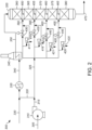
- FIG. 2 another embodiment of the present invention is shown in relation to a hydroprocessing unit 300.
- hydrogen stream 305 is compressed in compressor 310.
- the compressed hydrogen stream 315 is split into first and second portions, hydrogen streams 320 and 325.
- First hydrogen stream 320 is mixed with the hydrocarbon feed stream 330 and sent through heat exchanger 335 to raise the temperature.
- the partially heated feed stream 340 is sent to fired heater 345 to raise the temperature of the feed stream 350 exiting the fired heater 345 to the desired inlet temperature for the hydroprocessing reaction zone 355.
- Second hydrogen stream 325 is divided into four hydrogen quench streams 390, 395, 400, 405.
- Each of the hydrogen quench streams 390, 395, 400, 405 has a turbine 410, 415, 420, 425 configured to generate power and control the flow of hydrogen entering the hydroprocessing bed as well as a control valve 430, 435, 440, 445 to control the flow of hydrogen entering the hydroprocessing bed.
- the turbines 410, 415, 420, 425 each include a supersonic separator 411, 416, 421, 426 and thus may have the configuration shown in FIGURE 1 , discussed above.
- Hydrogen quench streams 390, 395, 400, 405 can be directed through either the turbine 410, 415, 420, 425, the control valve 430, 435, 440, 445, or both.
- a first fraction of the second hydrogen stream 325 can be directed to the first supersonic separator 411 and turbine 410, and a second fraction can be directed to the control valve 430.
- the first fraction can vary from 0% to 100% and the second fraction can vary from 100% to 0%.
- the flow of the hydrogen quench streams 390, 395, 400, 405 can be controlled by the turbines 410, 415, 420, 425, the control valves 430, 435, 440, 445, or both, allowing excellent process flexibility in systems including both.
- heavier compounds are more likely to be removed from the quench streams 390, 395, 400, 405 from the turbines 410, 415, 420, 425.
- hydroprocessing reaction zone 355 has five hydroprocessing beds 360, 365, 370, 375, and 380.
- Feed stream 350 which contains hydrogen and hydrocarbon feed to be hydroprocessed, enters the first hydroprocessing bed 360 where it undergoes hydroprocessing.
- the effluent from the first hydroprocessing bed 360 is mixed with first hydrogen quench stream 390 to form first quenched hydroprocessed stream 450.
- the first quenched hydroprocessed stream 450 is sent to the second hydroprocessing bed 365 where it undergoes further hydroprocessing.
- the effluent from the second hydroprocessing bed 365 is mixed with second hydrogen quench stream 395 to form second quenched hydroprocessed stream 455.
- the second quenched hydroprocessed stream 455 is sent to the third hydroprocessing bed 370 where it undergoes further hydroprocessing.
- the effluent from the third hydroprocessing bed 370 is mixed with third hydrogen quench stream 400 to form third quenched hydroprocessed stream 460.
- the third quenched hydroprocessed stream 460 is sent to the fourth hydroprocessing bed 375 where it undergoes further hydroprocessing.
- the effluent from the fourth hydroprocessing bed 375 is mixed with fourth hydrogen quench stream 405 to form fourth quenched hydroprocessed stream 465.
- the fourth quenched hydroprocessed stream 465 is sent to the fifth hydroprocessing bed 380 where it undergoes further hydroprocessing.
- the effluent 470 from the fifth hydroprocessing bed 380 can be sent to various processing zones, as described above.
- the effluent 470 typically is heat exchanged with the feed, passed to a water wash to extract and dissolve salts, air or water cooled with a condensing heat exchange, and subjected to a vapor liquid separation to provide a recycle gas and liquid--which is passed to subsequent stripping and distillative fractionation.
- the recycle gas stream would be amine treated to remove hydrogen sulfide, combined with make-up hydrogen before or after recompression in a recycle gas compressor and returned to the hydroprocessing reaction zone 355 via the combining with the reactor inlet hydrocarbon stream or as quench gas streams along the length of the reactor.
- the chemical processing units used in the present processes utilize a process control system.
- the process control system described in connection with the embodiments disclosed herein may be implemented or performed on the computer with a general purpose processor, a digital signal processor (DSP), an application specific integrated circuit (ASIC), a field programmable gate array (FPGA) or other programmable logic device, discrete gate or transistor logic, discrete hardware components, or any combination thereof designed to perform the functions described herein.
- a general-purpose processor may be a microprocessor, or, the processor may be any conventional processor, controller, microcontroller, or state machine.
- a processor may also be a combination of computing devices, e.g., a combination of a DSP and a microprocessor, two or more microprocessors, or any other combination of the foregoing.
- a software module may reside in RAM memory, flash memory, ROM memory, EPROM memory, EEPROM memory, registers, hard disk, a removable disk, a CD-ROM, or any other form of storage medium known in the art.
- An exemplary storage medium is in communication with the processor reading information from, and writing information to, the storage medium. This includes the storage medium being integral to or with the processor.
- the processor and the storage medium may reside in an ASIC.
- the ASIC may reside in a user terminal.
- the processor and the storage medium may reside as discrete components in a user terminal.
- processors and storage medium or memory are also typically in communication with hardware (e.g., ports, interfaces, antennas, amplifiers, signal processors, etc.) that allow for wired or wireless communication between different components, computers processors, or the like, such as between the input channel, a processor of the control logic, the output channels within the control system and the operator station in the control center.
- hardware e.g., ports, interfaces, antennas, amplifiers, signal processors, etc.
- the transmission of the data or information can be a wireless transmission (for example by Wi-Fi or Bluetooth) or a wired transmission (for example using an Ethernet RJ45 cable or an USB cable).
- a wireless transceiver for example a Wi-Fi transceiver
- the transmission can be performed automatically, at the request of the computers, in response to a request from a computer, or in other ways. Data can be pushed, pulled, fetched, etc., in any combination, or transmitted and received in any other manner.
- the process control system receives information relative to an amount of electricity generated by the turbines 14, 410, 415, 420, 425. It is contemplated that the turbine 14, 410, 415, 420, 425 determines the amount of electricity it has generated, or alternatively, the process control system receiving the information determines the amount of electricity that has been generated. In either configuration, the amount of the electricity generated by the turbines 14, 410, 415, 420, 425 is displayed on at least one display screen 50 (for example in communication with the computer 44 in the control center 46).
- the processing control system receives information associated with the amount of electricity generated by each of the turbines 14, 410, 415, 420, 425.
- the processing control system determines a total power generated based upon the information associated with the each of the turbines 14, 410, 415, 420, 425and displays that the total power generated.
- the total power generated may be displayed instead of or in conjunction with the display of the power generated by individual turbines 14, 410, 415, 420, 425.
- the processes according to the present invention provide for the various processing conditions associated with the processing units to be adjusted into order to lower the energy added to the steam initially. It is contemplated that the process control system receives information associated with the throughput of the processing unit, and determines a target power generated value for the turbines 14, 410, 415, 420, 425, since the electricity represents energy that is typically added to the overall processing unit. The determination of the target power generated value may be done when the electricity is at or near a predetermined level.
- the process control system will analyze one or more changes to the various processing conditions associated with the processing unit to lower the amount of energy recovered by the turbines 14, 410, 415, 420, 425.
- the processing conditions are adjusted without adjusting the throughput of the processing unit. This allows for the processing unit to have the same output, but with a lower operating input.
- the process control software may calculate and display the difference between the target power generated value and the total power generated on the at least one display screen 50.
- the process control system receives information associated with the throughput of the processing unit, and determines a target electrical power generated value for the turbine(s) 14, 410, 415, 420, 425 since the electricity represents energy that is typically added to the overall processing unit.
- the determination of the target electrical power generated value may be done when the electricity is at or near a predetermined level. In other words, if the amount of electricity produced meets or exceeds a predetermined level, the processing simulation system can determine one or more processing conditions to adjust and lower the amount of electricity generated until it reaches the target electrical power generated value.
- the process simulation system will analyze one or more changes to the various processing conditions associated with the processing unit to lower the amount of energy recovered by the turbine 14, 410, 415, 420, 425.
- the processing conditions are adjusted without adjusting the throughput of the processing unit. This allows for the processing unit to have the same throughput, but with a lower operating cost.
- the process simulation software may calculate and display the difference between the target electrical power generated value and the total electrical power generated on the at least one display screen 50.
- the process simulation software may determine that the total electrical power generated exceeds a predetermined level. Accordingly, the process simulation software determines the target electrical power generated value. Based upon other data and information received from other sensors and data collection devices typically associated with the processing unit, the process simulation software determines that the pressure provided by a compressor associated with the vapor stream can be lowered. While maintaining the throughput of the processing unit, an operating condition of the compressor is adjusted to provide a vapor stream 18 that still needs a pressure reduction in the turbine 14, 410, 415, 420, 425, but the difference between the two pressures is smaller. While this may lower the electricity generated by the turbine 14, 410, 415, 420, 425, the lower pressure for the compressor output requires less energy to achieve and provides a lower operating cost for the same throughput.
- the processing units are provided with opportunities to lower the energy input associated with the overall processing unit and increase profits by utilizing more energy efficient processes.
- a first embodiment of the present invention is an apparatus for generating electricity, the apparatus comprising: a body containing a supersonic separation device with an inlet configured to receive a vapor stream, a first outlet for a superheated vapor stream, and a second outlet for a liquid stream; a baffle disposed within the body and configured to impart a swirl at or above sonic velocity to the vapor stream; an internal cavity in the body between the inlet, the first outlet and the second outlet.
- the apparatus further comprises a turbine having a turbine wheel configured to transmit rotational movement from the superheated vapor stream to an electrical generator, the turbine wheel disposed between the first outlet and the internal cavity.
- a second embodiment of the invention is a process for recovering power from a vapor stream using the above-mentioned apparatus, the process comprising condensing a portion of the vapor stream in the supersonic separation device, the supersonic separation device configured to impart a swirl at or above a sonic velocity on the vapor stream passing therethrough; separating the liquid stream condensed portion from the vapor stream with the supersonic separation device to provide Z the superheated vapor stream; and recovering power from the superheated vapor stream in the turbine, the turbine comprising the turbine wheel configured to transmit rotational movement to the electrical generator.
- An embodiment of the invention is one, any or all of prior embodiments in this paragraph up through the first embodiment in this paragraph, wherein the superheated vapor stream has at least 2 °C more superheat than the vapor stream.
- An embodiment of the invention is one, any or all of prior embodiments in this paragraph up through the first embodiment in this paragraph, wherein a temperature of the vapor stream is less than 10 °C above a dew point of the vapor stream.
- An embodiment of the invention is one, any or all of prior embodiments in this paragraph up through the first embodiment in this paragraph, wherein the temperature of the vapor stream is less than 5 °C above a dew point of the vapor stream.
- An embodiment of the invention is one, any or all of prior embodiments in this paragraph up through the first embodiment in this paragraph, wherein the vapor stream comprises hydrogen and light hydrocarbons.
- An embodiment of the invention is one, any or all of prior embodiments in this paragraph up through the first embodiment in this paragraph, wherein the condensed portion comprises the light hydrocarbons.
- An embodiment not covered by the invention is one wherein the supersonic separation device and the turbine are integral with each other.
Landscapes
- Engineering & Computer Science (AREA)
- Mechanical Engineering (AREA)
- General Engineering & Computer Science (AREA)
- Chemical & Material Sciences (AREA)
- Combustion & Propulsion (AREA)
- Chemical Kinetics & Catalysis (AREA)
- Engine Equipment That Uses Special Cycles (AREA)
- Separating Particles In Gases By Inertia (AREA)
Description
- This invention relates generally to a turbine used in vapor stream in a chemical processing or refining plant, and more particularly to a turbine used with a vapor stream that is at or near its dew point.
- Chemical refining and processing methods frequently involve gaseous or vapor streams that are passed through control valves. The control valves are used to control the flow, upstream or downstream pressure, temperatures, or levels, etc. In the control valve, mechanical energy is dissipated. Since the energy is dissipated, without recovery, the energy is lost.
- Moreover, the lost energy is often associated with energy added to the system. Thus, there is an inherent inefficiency in the process associated with supplying energy only to remove it without recovery. However, since the costs of supply in the energy are typically relatively small compared to the cost of recovering it instead of dissipating it, refiners and processors often operate the processing/refining unit with this inefficiency to maintain throughput of the processing/refining unit at minimal investment and operating complexity. Nevertheless, this inefficiency is an opportunity for processors to lower operating costs and, thus increase profits.
- It has recently been discovered by the applicant that the control valves can be replaced with turbines to address these problems at scales smaller than have been possible in the past. Two things are making the smaller scale turbines more feasible. First, for example, devices such as discussed in Hawkins, LA; et al, Development of 125 kW ANM Expander/Generator for Waste Heat Recovery, J. of Engineering for Gas Turbines and Power, July 2011, 133, Pg 072503-1 to 6 show that designs using magnetic bearings and employing other compact design techniques can greatly reduce the cost and size of a turbine to the point of being economically applicable on a scale of <150 kW. Second, many chemical plant operators are seeing new regulatory and economic drivers towards energy recovery as governments either incent or compel chemical plants and refineries to reduce their net energy consumption. So, replacing control valves with turbines is being driven from both the improving turbine generator technology and improved economics for generating power.
- In some applications within the processing unit, the turbine could potentially be problematic. Specifically, in a vapor stream at or near its dew point, when the vapor stream passes through the turbine and its pressure is reduced, the resultant vapor stream will partially condense forming a two-phase stream as a result of the cooling of expansion of the vapor. While there are currently turbines that are designed to accommodate the two-phase stream, such turbines are complicated in design and difficult to predict in operation.
- Therefore, there is a need for an effective and efficient device and process for utilizing a turbine with a vapor stream that is near its dew point that is simpler and provides a more consistent output.
- The present invention attempts to overcome one or more shortcomings discussed above. Specifically, according to the present invention, upstream of the turbine is a supersonic separator which separates out the heavier components before the vapor stream is passed to the turbine. The supersonic separator imparts a swirl at sonic or supersonic velocity to the vapor which condenses some of the heavier compounds into droplets. The droplets are separated from the remaining vapor phase components which are then passed to the turbine for a pressure reduction while generating electricity.
- Furthermore, the turbine is able to provide information about the amount of energy removed. This information may be utilized to in determining adjustments for various processing conditions which reduce the amount of energy added to the process. This permits the processor to more efficiently operate the processing unit without reducing the throughput of the processing unit.
- The present invention provides an apparatus for generating electricity which includes: a body containing a supersonic separation device with with an inlet configured to receive a vapor stream, a first outlet for a superheated vapor stream and, a second outlet for a liquid stream; a baffle disposed within the body and configured to impart a swirl at or above sonic velocity to the vapor stream; an internal cavity in the body between the inlet, the first outlet, and the second outlet. According to the invention, the apparatus further comprises a turbine having a turbine wheel configured to transmit rotational movement from the superheated vapor stream to an electrical generator, the turbine wheel disposed between the outlet and the internal cavity.
- The present invention provides also a process for recovering power from a vapor stream using the above-mentioned apparatus, the process comprising: condensing a portion of the vapor stream in the supersonic separation device, the supersonic separation device configured to impart a swirl at or above a sonic velocity on the vapor stream passing therethrough; separating the liquid stream condensed portion from the vapor stream with the supersonic separation device to provide the superheated vapor stream; and recovering power from the superheated vapor stream in the turbine, the turbine comprising the turbine wheel configured to transmit rotational movement to the electrical generator.
- Additional aspects, embodiments, and details of the invention, all of which may be combinable in any manner, are set forth in the following detailed description of the invention.
- One or more exemplary embodiments of the present invention will be described below in conjunction with the attached drawing in which:
-
Figure 1 depicts a partial cutaway schematic view of a device according to the present invention; and, -
Figure 2 depicts a hydroprocessing unit according to one or more embodiments of the present invention. - As mentioned above, the present invention provides a supersonic separating device upstream of a turbine. The supersonic separating device condenses a portion of a vapor stream that is at or near its due point. The remaining vapor portion, a superheated stream as a result of the heavier compounds being removed, is passed through the turbine, allowing the pressure to be reduced. The turbine generates electricity from this energy dissipation which is recovered or used elsewhere in the processing unit. The reduced pressure vapor stream is less likely to be a two-phase system and can be used as desired in the process unit.
- With these general principles in mind, one or more embodiments of the present invention will be described with the understanding that the following description is not intended to be limiting.
- An
exemplary device 10 according to the present invention is shown inFigure 1 . Thedevice 10 is used for generating electricity and a vapor stream with a lower pressure. Thedevice 10 includes asupersonic separator 12 and aturbine 14. It is contemplated that thesupersonic separator 12 and theturbine 14 are integrally formed as a single unit, i.e., the two are contained within a single body 15 (or housing) and are not connected to each other with any external conduits. This is merely a preferred configuration, and it is contemplated that the advantages and benefits of the present invention are achieved with thesupersonic separator 12 and theturbine 14 being discrete components as opposed to a single unit. - The particular configuration of the
supersonic separator 12 is not necessarily important for the practicing of the present invention. Exemplarysupersonic separators 12 are disclosed inU.S. Pat. Nos. 6,280,502 , which discloses an apparatus having the features specified in the preamble of claim 1, 6,962,199, 7,261,766, 7,318,849, 7,494,535, 8,257,458, 8,398,734, 7,909,912, 8,475,555, 8,657,930, and 9,034, 082. - Generally, the
supersonic separator 12 comprises aninlet 16 configured to receive avapor stream 18, afirst outlet 19 for asuperheated vapor stream 20 and, asecond outlet 22 for aliquid stream 24. Accordingly, in processes according to the present invention, thevapor stream 18 is at or near its dew point. Thus, thevapor stream 18 could be within 10 °C of a dew point of thevapor stream 18, within 5 °C of a dew point of thevapor stream 18, within 1 °C of a dew point of thevapor stream 18, or greater than the dew point of thevapor stream 18 but less than 1 °C from the dew point of thevapor stream 18. For example, thevapor stream 18 includes hydrogen gas and light hydrocarbons, hydrogen sulfide, ammonia, and water. By light hydrocarbons it is meant that the hydrocarbons in thevapor stream 18 comprise between one and six carbon atoms. - Within the
supersonic separator 12 one ormore baffles 26 impart a swirl at or above sonic velocity to thevapor stream 18. Downstream of the baffle(s) 26 thesupersonic separator 12 includes aninternal cavity 28. As is known in the art, within theinternal cavity 28, the swirling vapor stream causes the larger molecules and compounds within the swirling vapor stream to condense together for form droplets. The droplets separate from the vapor and are recovered as theliquid stream 24 from thesupersonic separator 12 via thesecond outlet 22. - Downstream of the
internal cavity 28, the vapor is asuperheated vapor stream 20 that is passed to theturbine 14. Thesuperheated vapor stream 20 has the same, or approximately the same temperature as thevapor stream 18. Depending on the composition of thevapor stream 18, thesuperheated vapor stream 20 may or may not have a different chemical composition than thevapor stream 18. It is contemplated that thesuperheated vapor stream 20 has at least 2 °C more superheat thevapor stream 18. Thesuperheated vapor stream 20 is passed to theturbine 14 for a pressure reduction and to generate electricity. - The particular configuration of the
turbine 14 is not necessarily important for the practicing of the present invention.Exemplary turbines 14 are disclosed inU.S. Pat. Nos. 4,625,125 ,4,694,189 ,4,754,156 , and9,203,269 - Generally, the
turbine 14 includes aturbine wheel 30 withblades 32 configured to transfer, or transmit, rotational movement, created by the flow of a fluid stream passing theturbine wheel 30, to anelectrical generator 34. Theelectrical generator 34 generally includes a first winding 36, in communication with theturbine wheel 30 and a second winding 38 surrounding the first winding 36 and stationary with respect to the first winding 36. As will be appreciated, the rotation of the first winding 36 creates an electrical current in the second winding 38. Additionally, theturbine 14 may include aprocessor 40 configured to measure an amount of electricity generated by theturbine 14 and atransmitter 42 configured to transmit information associated with the amount of electricity generated by theturbine 14 to acomputer 44 at acontrol center 46 for the processing unit (discussed in more detail below). - Within the
turbine 14, thesuperheated vapor stream 20 passing therethrough will rotate theturbine wheel 30 and, as is known, generate electricity via theelectrical generator 34. At the same time the pressure of thesuperheated vapor stream 20 is reduced to provide a lowpressure vapor stream 48 having a pressure that is less than the superheated vapor stream 20 (and the vapor stream 18). By utilizing thesupersonic separator 12 before theturbine 14, the lowpressure vapor stream 48 is less likely to be two-phase-even though thevapor stream 18 was at or near its dew point. Additionally, unlike processes which utilize control valves for the pressure reduction, the present invention provides for the conversion of some of the energy removed via the pressure reductions to electricity. - In some embodiments not covered by the present invention, the process comprises directing a portion of a gaseous process stream through one or more variable-resistance turbines to control the flowrate of the gas process stream and, optionally, generate electric power therefrom; controlling a pressure and temperature of the gaseous process stream so that the gas exiting the power-recovery turbine remains in the gas phase; and measuring the flowrate or controlling the flowrate or both using a variable nozzle turbine, inlet variable guide vanes, or direct coupled variable electric load, to name a few, to vary the resistance to flow through the turbine. Again, the resistance to rotation of the variable-resistance turbine can be varied by an external variable load electric circuit which is in a magnetic field from a magnet(s) that is rotating on the turbine. As more load is put on the circuit, there is more resistance to rotation on the turbine. This in turn imparts more pressure drop across the turbine and slows the process stream flow. An algorithm in the device can also calculate the actual flow through the device by measuring the turbine RPMs and the load on the circuit. The resistance to rotation flow can also be varied by variable position inlet guide vanes. In some embodiments, the power will be generated via power-recovery turbines with variable resistance to flow made possible by either guide vanes or variable load on the electrical power generation circuit. An algorithm to calculate actual flow using the guide vanes position, power output and RPMs can be used.
- If slow control response of the turbine is an issue then the use of the turbine is limited to slow responding or "loose" control point applications. A slow responding application is contemplated to have a response time to reach half way (i.e., 50% of a difference) between a new (or target) steady state condition (e.g., temperature, pressure, flow rate) from an original (or starting) steady state condition when the new (or target) condition differs from the original (or stating) condition of at least 10%, is of at least one second, or even greater, for example, ten seconds, at least one minute, at least ten minutes, or an hour or more, for half of the change to completed.
- Turning to
Figure 2 , another embodiment of the present invention is shown in relation to ahydroprocessing unit 300. In the depicted embodiment,hydrogen stream 305 is compressed incompressor 310. Thecompressed hydrogen stream 315 is split into first and second portions, hydrogen streams 320 and 325.First hydrogen stream 320 is mixed with thehydrocarbon feed stream 330 and sent throughheat exchanger 335 to raise the temperature. The partiallyheated feed stream 340 is sent to firedheater 345 to raise the temperature of thefeed stream 350 exiting the firedheater 345 to the desired inlet temperature for thehydroprocessing reaction zone 355. -
Second hydrogen stream 325 is divided into four hydrogen quenchstreams streams turbine control valve turbines supersonic separator FIGURE 1 , discussed above. - Hydrogen quench
streams turbine control valve - For example, a first fraction of the
second hydrogen stream 325 can be directed to the firstsupersonic separator 411 and turbine 410, and a second fraction can be directed to thecontrol valve 430. The first fraction can vary from 0% to 100% and the second fraction can vary from 100% to 0%. The same applies to the remain fractions sent to theother control valves turbines supersonic separators streams turbines control valves supersonic separators turbines - As shown,
hydroprocessing reaction zone 355 has fivehydroprocessing beds Feed stream 350, which contains hydrogen and hydrocarbon feed to be hydroprocessed, enters thefirst hydroprocessing bed 360 where it undergoes hydroprocessing. The effluent from thefirst hydroprocessing bed 360 is mixed with first hydrogen quenchstream 390 to form first quenchedhydroprocessed stream 450. - The first quenched
hydroprocessed stream 450 is sent to thesecond hydroprocessing bed 365 where it undergoes further hydroprocessing. The effluent from thesecond hydroprocessing bed 365 is mixed with second hydrogen quenchstream 395 to form second quenchedhydroprocessed stream 455. The second quenchedhydroprocessed stream 455 is sent to thethird hydroprocessing bed 370 where it undergoes further hydroprocessing. The effluent from thethird hydroprocessing bed 370 is mixed with third hydrogen quenchstream 400 to form third quenchedhydroprocessed stream 460. The third quenchedhydroprocessed stream 460 is sent to thefourth hydroprocessing bed 375 where it undergoes further hydroprocessing. The effluent from thefourth hydroprocessing bed 375 is mixed with fourth hydrogen quenchstream 405 to form fourth quenchedhydroprocessed stream 465. The fourth quenchedhydroprocessed stream 465 is sent to thefifth hydroprocessing bed 380 where it undergoes further hydroprocessing. The effluent 470 from thefifth hydroprocessing bed 380 can be sent to various processing zones, as described above. - Although not depicted as such, the
effluent 470 typically is heat exchanged with the feed, passed to a water wash to extract and dissolve salts, air or water cooled with a condensing heat exchange, and subjected to a vapor liquid separation to provide a recycle gas and liquid--which is passed to subsequent stripping and distillative fractionation. The recycle gas stream would be amine treated to remove hydrogen sulfide, combined with make-up hydrogen before or after recompression in a recycle gas compressor and returned to thehydroprocessing reaction zone 355 via the combining with the reactor inlet hydrocarbon stream or as quench gas streams along the length of the reactor. - As will be appreciated, the chemical processing units used in the present processes, such as the
hydroprocessing unit 300, utilize a process control system. The process control system described in connection with the embodiments disclosed herein may be implemented or performed on the computer with a general purpose processor, a digital signal processor (DSP), an application specific integrated circuit (ASIC), a field programmable gate array (FPGA) or other programmable logic device, discrete gate or transistor logic, discrete hardware components, or any combination thereof designed to perform the functions described herein. A general-purpose processor may be a microprocessor, or, the processor may be any conventional processor, controller, microcontroller, or state machine. A processor may also be a combination of computing devices, e.g., a combination of a DSP and a microprocessor, two or more microprocessors, or any other combination of the foregoing. - The steps of the processes associated with the process control system may be embodied in an algorithm contained directly in hardware, in a software module executed by a 5 processor, or in a combination of the two. A software module may reside in RAM memory, flash memory, ROM memory, EPROM memory, EEPROM memory, registers, hard disk, a removable disk, a CD-ROM, or any other form of storage medium known in the art. An exemplary storage medium is in communication with the processor reading information from, and writing information to, the storage medium. This includes the storage medium being integral to or with the processor. The processor and the storage medium may reside in an ASIC. The ASIC may reside in a user terminal. Alternatively, the processor and the storage medium may reside as discrete components in a user terminal. These devices are merely intended to be exemplary, non-limiting examples of a computer readable storage medium. The processor and storage medium or memory are also typically in communication with hardware (e.g., ports, interfaces, antennas, amplifiers, signal processors, etc.) that allow for wired or wireless communication between different components, computers processors, or the like, such as between the input channel, a processor of the control logic, the output channels within the control system and the operator station in the control center.
- In communication relative to computers and processors refers to the ability to transmit and receive information or data. The transmission of the data or information can be a wireless transmission (for example by Wi-Fi or Bluetooth) or a wired transmission (for example using an Ethernet RJ45 cable or an USB cable). For a wireless transmission, a wireless transceiver (for example a Wi-Fi transceiver) is in communication with each processor or computer. The transmission can be performed automatically, at the request of the computers, in response to a request from a computer, or in other ways. Data can be pushed, pulled, fetched, etc., in any combination, or transmitted and received in any other manner.
- fit is contemplated that the process control system receives information relative to an amount of electricity generated by the
turbines turbine turbines computer 44 in the control center 46). If the processing unit comprises a plurality ofturbines turbines turbines individual turbines - As discussed above, the recovery of the electricity is oftentimes based upon the need to remove energy from the streams that has already been added to the streams in the processing units. Thus, it is contemplated that the processes according to the present invention provide for the various processing conditions associated with the processing units to be adjusted into order to lower the energy added to the steam initially. It is contemplated that the process control system receives information associated with the throughput of the processing unit, and determines a target power generated value for the
turbines turbines display screen 50. - It is contemplated that the process control system receives information associated with the throughput of the processing unit, and determines a target electrical power generated value for the turbine(s) 14, 410, 415, 420, 425 since the electricity represents energy that is typically added to the overall processing unit. The determination of the target electrical power generated value may be done when the electricity is at or near a predetermined level. In other words, if the amount of electricity produced meets or exceeds a predetermined level, the processing simulation system can determine one or more processing conditions to adjust and lower the amount of electricity generated until it reaches the target electrical power generated value.
- Thus, the process simulation system will analyze one or more changes to the various processing conditions associated with the processing unit to lower the amount of energy recovered by the
turbine display screen 50. - For example, the process simulation software may determine that the total electrical power generated exceeds a predetermined level. Accordingly, the process simulation software determines the target electrical power generated value. Based upon other data and information received from other sensors and data collection devices typically associated with the processing unit, the process simulation software determines that the pressure provided by a compressor associated with the vapor stream can be lowered. While maintaining the throughput of the processing unit, an operating condition of the compressor is adjusted to provide a
vapor stream 18 that still needs a pressure reduction in theturbine turbine - Thus, not only does the present invention reduce the chance that the low
pressure vapor stream 48 is a two-phase stream, the processing units are provided with opportunities to lower the energy input associated with the overall processing unit and increase profits by utilizing more energy efficient processes. - It should be appreciated and understood by those of ordinary skill in the art that various other components such as valves, pumps, filters, coolers, etc. were not shown in the drawings as it is believed that the specifics of same are well within the knowledge of those of ordinary skill in the art and a description of same is not necessary for practicing or understanding the embodiments of the present invention.
- Those of skill in the art will appreciate that the illustrative logical instruction, steps, blocks, modules, and circuits described in the present application may be implemented as electronic hardware, computer software, or combinations of both. Some of the embodiments and implementations are described herein based upon functional and/or logical block components (or modules) and various steps. However, those of ordinary skill in the art will appreciate that these steps and block components (or modules) may be realized by any number of hardware, software, and/or firmware components configured to perform the specified functions Thus, based upon the interchangeability of hardware and software, the various steps, components, blocks, modules, and circuits are described herein generally in terms of their functionality. Whether such functionality is implemented as hardware or software depends upon the any design constraints imposed on the overall system and can vary for each different application of the present invention. A person of ordinary skill in the art may implement this functionality in diverse ways for each particular application, but such implementation decisions should not be interpreted as causing a departure from the scope of the present invention.
- While the following is described in conjunction with specific embodiments, it will be understood that this description is intended to illustrate and not limit the scope of the preceding description and the appended claims.
- A first embodiment of the present invention is an apparatus for generating electricity, the apparatus comprising: a body containing a supersonic separation device with an inlet configured to receive a vapor stream, a first outlet for a superheated vapor stream, and a second outlet for a liquid stream; a baffle disposed within the body and configured to impart a swirl at or above sonic velocity to the vapor stream; an internal cavity in the body between the inlet, the first outlet and the second outlet. According to the invention, the apparatus further comprises a turbine having a turbine wheel configured to transmit rotational movement from the superheated vapor stream to an electrical generator, the turbine wheel disposed between the first outlet and the internal cavity. A second embodiment of the invention is a process for recovering power from a vapor stream using the above-mentioned apparatus, the process comprising condensing a portion of the vapor stream in the supersonic separation device, the supersonic separation device configured to impart a swirl at or above a sonic velocity on the vapor stream passing therethrough; separating the liquid stream condensed portion from the vapor stream with the supersonic separation device to provide Z the superheated vapor stream; and recovering power from the superheated vapor stream in the turbine, the turbine comprising the turbine wheel configured to transmit rotational movement to the electrical generator. An embodiment of the invention is one, any or all of prior embodiments in this paragraph up through the first embodiment in this paragraph, wherein the superheated vapor stream has at least 2 °C more superheat than the vapor stream. An embodiment of the invention is one, any or all of prior embodiments in this paragraph up through the first embodiment in this paragraph, wherein a temperature of the vapor stream is less than 10 °C above a dew point of the vapor stream. An embodiment of the invention is one, any or all of prior embodiments in this paragraph up through the first embodiment in this paragraph, wherein the temperature of the vapor stream is less than 5 °C above a dew point of the vapor stream. An embodiment of the invention is one, any or all of prior embodiments in this paragraph up through the first embodiment in this paragraph, wherein the vapor stream comprises hydrogen and light hydrocarbons. An embodiment of the invention is one, any or all of prior embodiments in this paragraph up through the first embodiment in this paragraph, wherein the condensed portion comprises the light hydrocarbons. An embodiment not covered by the invention is one wherein the supersonic separation device and the turbine are integral with each other.
- Without further elaboration, it is believed that using the preceding description that one skilled in the art can utilize the present invention to its fullest extent and easily ascertain the essential characteristics of this invention, without departing from the scope thereof, to make various changes and modifications of the invention and to adapt it to various usages and conditions. The preceding preferred specific embodiments are, therefore, to be construed as merely illustrative, and not limiting the remainder of the disclosure in any way whatsoever, and that it is intended to cover various modifications and equivalent arrangements included within the scope of the appended claims.
- In the foregoing, all temperatures are set forth in degrees Celsius and, all parts and percentages are by weight, unless otherwise indicated.
- While at least one exemplary embodiment has been presented in the foregoing detailed description of the invention, it should be appreciated that a vast number of variations exist. It should also be appreciated that the exemplary embodiment or exemplary embodiments are only examples, and are not intended to limit the scope, applicability, or configuration of the invention in any way. Rather, the foregoing detailed description will provide those skilled in the art with a convenient road map for implementing an exemplary embodiment of the invention, it being understood that various changes may be made in the function and arrangement of elements described in an exemplary embodiment without departing from the scope of the invention as set forth in the appended claims and their legal equivalents.
Claims (9)
- An apparatus for generating electricity, the apparatus comprising:a body (15) containing a supersonic separation device (12)with an inlet (16) configured to receive a vapor stream (18), a first outlet (19) for a superheated vapor stream (20), and, a second outlet (22) for a liquid stream (24);a baffle (26) disposed within the body (15) and configured to impart a swirl at or above sonic velocity to the vapor stream (20);an internal cavity (28) in the body (15) between the inlet (16), the first outlet (19), and the second outlet (22); characterised in that the apparatus further comprises a turbine havinga turbine wheel (30) configured to transmit rotational movement from the superheated vapor stream (20) to an electrical generator (34), the turbine wheel (30) disposed between the first outlet (19) and the internal cavity (28).
- A process for recovering power from a vapor stream (18, 390, 395, 400, 405) using the apparatus of claim 1, the process comprising:condensing a portion of the vapor stream (18, 390, 395, 400, 405) in the supersonic separation device (12), the supersonic separation device (12, 411, 416, 421, 426) configured to impart a swirl at or above a sonic velocity on the vapor stream (18, 390, 395, 400, 405) passing therethrough;separating the liquid stream condensed portion (24) from the vapor stream (18, 390, 395, 400, 405) with the supersonic separation device (12) to provide the a superheated vapor stream (20);and, recovering power from the superheated vapor stream in the turbine (14, 410, 415, 420, 425), the turbine (14, 410, 415, 420, 425) comprising the turbine wheel (30) configured to transmit rotational movement to the electrical generator (34).
- The process of claim 2, wherein the superheated vapor stream (20) has at least 2 °C more superheat than the vapor stream (18, 390, 395, 400, 405).
- The process of claim 2, r wherein a temperature of the vapor stream (18, 390, 395, 400, 405) is less than 10 °C above a dew point of the vapor stream (18, 390, 395, 400, 405).
- The process of claim 4, wherein the temperature of the vapor stream (18, 390, 395, 400, 405) is less than 5 °C above a dew point of the vapor stream (18, 390, 395, 400, 405).
- The process of any one claims 2 to 5, wherein the vapor stream (18, 390, 395, 400, 405) comprises hydrogen and light hydrocarbons.
- The process of claim 6, wherein the condensed portion (24) comprises the light hydrocarbons.
- The process of any one claims 2 to 5, wherein the vapor stream (18, 390, 395, 400, 405) is part of a processing unit (300), and the process further comprising:receiving information from the turbine (14, 410, 415, 420, 425) relative to an amount of electricity generated by the turbine (14, 410, 415, 420, 425);receiving information associated with a throughput of the processing unit (300); and,determining a power generated target value based in part on the information associated with the throughput of the processing unit (300).
- The process of claim 8 further comprising:
maintaining the throughput of the processing unit (300) while adjusting at least one process parameter of the processing unit (300) based upon the power generated target value.
Applications Claiming Priority (2)
| Application Number | Priority Date | Filing Date | Title |
|---|---|---|---|
| US15/923,990 US10794225B2 (en) | 2018-03-16 | 2018-03-16 | Turbine with supersonic separation |
| PCT/US2019/022436 WO2019178459A1 (en) | 2018-03-16 | 2019-03-15 | Turbine with supersonic separation |
Publications (3)
| Publication Number | Publication Date |
|---|---|
| EP3765171A1 EP3765171A1 (en) | 2021-01-20 |
| EP3765171A4 EP3765171A4 (en) | 2022-01-05 |
| EP3765171B1 true EP3765171B1 (en) | 2024-01-17 |
Family
ID=67904506
Family Applications (1)
| Application Number | Title | Priority Date | Filing Date |
|---|---|---|---|
| EP19767007.8A Active EP3765171B1 (en) | 2018-03-16 | 2019-03-15 | Turbine with supersonic separation |
Country Status (4)
| Country | Link |
|---|---|
| US (1) | US10794225B2 (en) |
| EP (1) | EP3765171B1 (en) |
| JP (1) | JP7110376B2 (en) |
| WO (1) | WO2019178459A1 (en) |
Families Citing this family (3)
| Publication number | Priority date | Publication date | Assignee | Title |
|---|---|---|---|---|
| US10871085B2 (en) | 2018-03-16 | 2020-12-22 | Uop Llc | Energy-recovery turbines for gas streams |
| US10829698B2 (en) | 2018-03-16 | 2020-11-10 | Uop Llc | Power recovery from quench and dilution vapor streams |
| NL2022927B1 (en) * | 2019-04-11 | 2020-10-20 | Twister Bv | Cyclonic fluid separator |
Family Cites Families (72)
| Publication number | Priority date | Publication date | Assignee | Title |
|---|---|---|---|---|
| US4455614A (en) | 1973-09-21 | 1984-06-19 | Westinghouse Electric Corp. | Gas turbine and steam turbine combined cycle electric power generating plant having a coordinated and hybridized control system and an improved factory based method for making and testing combined cycle and other power plants and control systems therefor |
| US4106294A (en) * | 1977-02-02 | 1978-08-15 | Julius Czaja | Thermodynamic process and latent heat engine |
| LU80763A1 (en) | 1978-01-09 | 1979-05-16 | Lenz K | PROCEDURE AND ARRANGEMENT FOR CONTROLLING, MONITORING AND MEASURING CONSUMPTION OF A FLUID FLOW VALVE |
| US4285481A (en) | 1979-06-04 | 1981-08-25 | Biscomb Lloyd I | Multiple wind turbine tethered airfoil wind energy conversion system |
| US4292050A (en) * | 1979-11-15 | 1981-09-29 | Linhardt & Associates, Inc. | Curved duct separator for removing particulate matter from a carrier gas |
| GR1000927B (en) * | 1990-08-10 | 1993-03-16 | Method and mechanism for the supersonic separation of a flow gas and droplets | |
| US5167123A (en) * | 1992-01-13 | 1992-12-01 | Brandon Ronald E | Flow condensing diffusers for saturated vapor applications |
| EP0552039A1 (en) | 1992-01-17 | 1993-07-21 | Gec-Marconi Limited | Transmitter tuning |
| US5385121A (en) * | 1993-01-19 | 1995-01-31 | Keystone International Holdings Corp. | Steam desuperheater |
| US5384489A (en) | 1994-02-07 | 1995-01-24 | Bellac; Alphonse H. | Wind-powered electricity generating system including wind energy storage |
| US6009711A (en) | 1997-08-14 | 2000-01-04 | Ormat Industries Ltd. | Apparatus and method for producing power using geothermal fluid |
| WO2004084371A1 (en) | 1998-08-31 | 2004-09-30 | Kaoru Fujita | Method and apparatus for optimization control of power plant |
| US6524368B2 (en) * | 1998-12-31 | 2003-02-25 | Shell Oil Company | Supersonic separator apparatus and method |
| US6280502B1 (en) * | 1998-12-31 | 2001-08-28 | Shell Oil Company | Removing solids from a fluid |
| WO2000040834A1 (en) | 1998-12-31 | 2000-07-13 | Shell Internationale Research Maatschappij B.V. | Method for removing condensables from a natural gas stream, at a wellhead, downstream of the wellhead choke |
| US6265453B1 (en) | 1999-07-01 | 2001-07-24 | Syntroleum Corporation | Hydrocarbon conversion system with enhanced combustor and method |
| US6261055B1 (en) * | 1999-08-03 | 2001-07-17 | Jerzy A. Owczarek | Exhaust flow diffuser for a steam turbine |
| US6354084B1 (en) | 1999-08-20 | 2002-03-12 | Cummins Engine Company, Inc. | Exhaust gas recirculation system for a turbocharged internal combustion engine |
| DE102009031557A1 (en) | 2009-03-02 | 2010-09-09 | Sms Siemag Ag | Energy recovery in hot strip mills by converting the cooling heat of the continuous casting plant and the residual heat of slabs and coils into electrical energy or other use of the captured process heat |
| US20020036430A1 (en) * | 2000-09-28 | 2002-03-28 | Welches Richard S. | Local area grid for distributed power |
| AU2003264846B2 (en) | 2002-04-29 | 2008-05-08 | Shell Internationale Research Maatschappij B.V. | Cyclonic fluid separator equipped with adjustable vortex finder position |
| CN1327933C (en) | 2002-04-29 | 2007-07-25 | 国际壳牌研究有限公司 | Supersonic fluid separation enhanced by spray injection |
| ATE497821T1 (en) | 2002-09-02 | 2011-02-15 | Shell Int Research | CYCLONE SEPARATOR FOR FLUID |
| US6898540B2 (en) | 2002-11-12 | 2005-05-24 | General Electric Company | System and method for displaying real-time turbine corrected output and heat rate |
| US6938425B2 (en) | 2003-08-11 | 2005-09-06 | Siemens Westinghouse Power Corporation | System and method for controlling water injection in a turbine engine |
| JP4915117B2 (en) | 2005-04-20 | 2012-04-11 | ソニー株式会社 | Vibration shock absorbing mechanism and content reproduction apparatus |
| WO2007025387A1 (en) | 2005-09-02 | 2007-03-08 | John Christopher Burtch | Apparatus for production of hydrogen gas using wind and wave action |
| US7757493B2 (en) | 2006-03-07 | 2010-07-20 | Uop Llc | Fluid catalytic cracking steam pressure letdown power recovery system and process |
| CN101512448B (en) | 2006-06-23 | 2012-11-14 | 沙特阿拉伯石油公司 | System and method for targeting and optimal driving force distribution in energy recovery systems |
| EP1974790A1 (en) | 2007-03-26 | 2008-10-01 | Twister B.V. | Cyclonic fluid separator |
| US8643471B2 (en) | 2007-06-15 | 2014-02-04 | Shell Oil Company | Method and system for state encoding |
| US20090125152A1 (en) | 2007-11-09 | 2009-05-14 | Markron Technologies, Llc | Method of measurement, control, and regulation for the solar thermal hybridization of a fossil fired rankine cycle |
| CN102203780B (en) | 2008-06-06 | 2014-06-25 | 沙特阿拉伯石油公司 | System and related methods for global targeting of process utilities under varying conditions |
| WO2010013999A1 (en) | 2008-08-01 | 2010-02-04 | Twister B.V. | Cyclonic separator with a volute outlet duct |
| RU2509272C2 (en) | 2009-02-05 | 2014-03-10 | Твистер Б. В. | Multi-stage cyclone separator for fluid medium |
| CA2758050C (en) | 2009-04-07 | 2017-11-21 | Twister B.V. | Separation system comprising a swirl valve |
| EP2301886A1 (en) | 2009-09-03 | 2011-03-30 | Ammonia Casale S.A. | Waste heat recovery in a chemical process and plant, particularly for the synthesis of ammonia |
| US8404918B2 (en) | 2009-09-28 | 2013-03-26 | Uop Llc | Energy efficiency in adsorptive separation |
| US20110100005A1 (en) | 2009-10-30 | 2011-05-05 | Sampson Glenn A | Water reclamation in a concentrated solar power-enabled power plant |
| EP3136313A1 (en) | 2009-12-05 | 2017-03-01 | Jens Mehnert | Method and device for analyzing the energy use during the operation of a production system |
| DE102010001118B4 (en) * | 2010-01-22 | 2021-05-12 | Robert Bosch Gmbh | Method for operating an internal combustion engine with a steam power plant |
| US8967590B2 (en) | 2010-03-02 | 2015-03-03 | Westlock Controls Corporation | Micro-power generator for valve control applications |
| CA2800822A1 (en) * | 2010-06-01 | 2011-12-08 | Shell Internationale Research Maatschappij B.V. | Separation of gases produced by combustion |
| US10184229B2 (en) * | 2010-07-30 | 2019-01-22 | Robert Kremer | Apparatus, system and method for utilizing thermal energy |
| FR2966814B1 (en) | 2010-10-28 | 2016-01-01 | IFP Energies Nouvelles | PROCESS FOR PRODUCING HYDROGEN BY VAPOREFORMING A PETROLEUM CUT WITH OPTIMIZED STEAM PRODUCTION |
| US20120227440A1 (en) | 2011-03-10 | 2012-09-13 | Alstom Technology Ltd. | System And Process For The Physical Absorption of Carbon Dioxide From a Flue Gas Stream |
| US9222410B2 (en) | 2011-04-13 | 2015-12-29 | General Electric Company | Power plant |
| CA2780451A1 (en) | 2011-06-21 | 2012-12-21 | Genalta Power, Inc. | Variable speed power generation from industrial fluid energy sources |
| US9085499B2 (en) | 2011-11-09 | 2015-07-21 | Uop Llc | Energy efficiency in adsorptive separation |
| EP2620703A1 (en) * | 2012-01-25 | 2013-07-31 | Siemens Aktiengesellschaft | Water injection device for a power plant bypass steam system |
| CA2899883A1 (en) | 2012-02-02 | 2013-08-08 | Electratherm, Inc. | Improved heat utilization in orc systems |
| GB2499991A (en) | 2012-03-05 | 2013-09-11 | Solaredge Technologies Ltd | DC link circuit for photovoltaic array |
| JP5984687B2 (en) * | 2013-01-17 | 2016-09-06 | 三菱日立パワーシステムズ株式会社 | Moisture separation heater and moisture separation heating equipment provided with the same |
| JP2016056808A (en) | 2013-01-29 | 2016-04-21 | 日立建機株式会社 | Work machine pressure oil energy recovery device |
| JP6010489B2 (en) | 2013-03-12 | 2016-10-19 | 三菱日立パワーシステムズ株式会社 | Thermoelectric variable cogeneration system |
| US8763625B1 (en) | 2013-04-12 | 2014-07-01 | John T. Carter | Siphon pump technology and apparatuses |
| JP5790952B2 (en) | 2013-04-23 | 2015-10-07 | 横河電機株式会社 | Production energy management system and computer program |
| WO2014178079A2 (en) | 2013-04-26 | 2014-11-06 | Eesavyasa Technologies Pvt. Ltd | Led lighting systems using compressed air based power generation and a method thereof |
| CN104463341B (en) | 2013-09-25 | 2017-10-27 | 北京宜能高科科技有限公司 | The steam power system analysis optimization method and apparatus of pictorialization |
| US9764272B2 (en) | 2013-10-28 | 2017-09-19 | Energy Recovery, Inc. | Systems and methods for utilizing turbine systems within gas processing systems |
| US20160252015A1 (en) | 2013-11-27 | 2016-09-01 | Hitachi, Ltd. | Gas Turbine Corresponding to Renewable Energy and Control Method Therefor |
| RU2570131C2 (en) | 2014-04-09 | 2015-12-10 | Федеральное государственное бюджетное образовательное учреждение высшего профессионального образования "Казанский государственный энергетический университет" (ФГБОУ ВПО "КГЭУ") | Operating method of thermal power plant |
| WO2015175610A1 (en) * | 2014-05-13 | 2015-11-19 | Holtec International | Steam conditioning system |
| AU2015284297B2 (en) | 2014-06-30 | 2020-02-20 | Robert Kremer | An apparatus, system and method for utilizing thermal energy |
| US20160141878A1 (en) | 2014-11-05 | 2016-05-19 | John Anton Johansen | Dc appliance system |
| US10088507B2 (en) | 2014-12-03 | 2018-10-02 | Saudi Arabian Oil Company | Energy performance metric in hydrocarbon-producing facilities |
| US11060032B2 (en) | 2015-01-02 | 2021-07-13 | Suncoke Technology And Development Llc | Integrated coke plant automation and optimization using advanced control and optimization techniques |
| ES2947567T3 (en) | 2015-05-06 | 2023-08-11 | Vestas Wind Sys As | Wind Turbine Power Generation System |
| JP6518526B2 (en) * | 2015-06-18 | 2019-05-22 | 三菱日立パワーシステムズ株式会社 | Axial flow turbine |
| US9803930B2 (en) | 2015-08-24 | 2017-10-31 | Saudi Arabian Oil Company | Power generation from waste heat in integrated hydrocracking and diesel hydrotreating facilities |
| US11107169B2 (en) * | 2015-11-18 | 2021-08-31 | General Electric Company | Systems and methods for controlling and monitoring power assets |
| CN206538206U (en) | 2016-11-29 | 2017-10-03 | 江苏悦达家纺有限公司 | It is a kind of can optimizing water quality heat reclamation device |
-
2018
- 2018-03-16 US US15/923,990 patent/US10794225B2/en active Active
-
2019
- 2019-03-15 JP JP2020547140A patent/JP7110376B2/en active Active
- 2019-03-15 WO PCT/US2019/022436 patent/WO2019178459A1/en active Application Filing
- 2019-03-15 EP EP19767007.8A patent/EP3765171B1/en active Active
Also Published As
| Publication number | Publication date |
|---|---|
| US20190284960A1 (en) | 2019-09-19 |
| JP7110376B2 (en) | 2022-08-01 |
| JP2021516613A (en) | 2021-07-08 |
| US10794225B2 (en) | 2020-10-06 |
| EP3765171A4 (en) | 2022-01-05 |
| EP3765171A1 (en) | 2021-01-20 |
| WO2019178459A1 (en) | 2019-09-19 |
Similar Documents
| Publication | Publication Date | Title |
|---|---|---|
| EP3765171B1 (en) | Turbine with supersonic separation | |
| US10690010B2 (en) | Steam reboiler with turbine | |
| EP3765583B1 (en) | Hydroprocessing unit with power recovery turbines | |
| EP3766168B1 (en) | Process improvement through the addition of power recovery turbine equipment in existing processes | |
| EP3765716B1 (en) | Use of recovered power in a process | |
| Bansal et al. | Feasibility of hydraulic power recovery from waste energy in bio-gas scrubbing processes | |
| US11713697B2 (en) | Energy-recovery turbines for gas streams | |
| JP7106666B2 (en) | Process for conditioning chemical treatment units by means of turbines | |
| Zherdev et al. | Comparative Analysis of Natural Gas Purification Efficiency for Low Degree of Expansion Using a Throttle and a High-Flow Three-Flow Vortex Tube | |
| Fakhari | Nucleation and Droplet Growth Rate of Homogeneously Condensing Flows within an industrial Steam turbine | |
| Tai et al. | Numerical Simulation of Two Phase Flow Characteristic in Dynamic-Static Separator | |
| Makrodimitri et al. | Molecular Modeling of Gas Treatment Processes with Emphasis to GTL Process |
Legal Events
| Date | Code | Title | Description |
|---|---|---|---|
| STAA | Information on the status of an ep patent application or granted ep patent |
Free format text: STATUS: THE INTERNATIONAL PUBLICATION HAS BEEN MADE |
|
| PUAI | Public reference made under article 153(3) epc to a published international application that has entered the european phase |
Free format text: ORIGINAL CODE: 0009012 |
|
| STAA | Information on the status of an ep patent application or granted ep patent |
Free format text: STATUS: REQUEST FOR EXAMINATION WAS MADE |
|
| 17P | Request for examination filed |
Effective date: 20200915 |
|
| AK | Designated contracting states |
Kind code of ref document: A1 Designated state(s): AL AT BE BG CH CY CZ DE DK EE ES FI FR GB GR HR HU IE IS IT LI LT LU LV MC MK MT NL NO PL PT RO RS SE SI SK SM TR |
|
| AX | Request for extension of the european patent |
Extension state: BA ME |
|
| DAV | Request for validation of the european patent (deleted) | ||
| DAX | Request for extension of the european patent (deleted) | ||
| A4 | Supplementary search report drawn up and despatched |
Effective date: 20211207 |
|
| RIC1 | Information provided on ipc code assigned before grant |
Ipc: F01K 17/06 20060101ALI20211201BHEP Ipc: F01D 15/10 20060101ALI20211201BHEP Ipc: B04C 9/00 20060101ALI20211201BHEP Ipc: F25J 3/06 20060101ALI20211201BHEP Ipc: B01D 45/12 20060101AFI20211201BHEP |
|
| P01 | Opt-out of the competence of the unified patent court (upc) registered |
Effective date: 20230421 |
|
| GRAP | Despatch of communication of intention to grant a patent |
Free format text: ORIGINAL CODE: EPIDOSNIGR1 |
|
| STAA | Information on the status of an ep patent application or granted ep patent |
Free format text: STATUS: GRANT OF PATENT IS INTENDED |
|
| INTG | Intention to grant announced |
Effective date: 20230904 |
|
| GRAS | Grant fee paid |
Free format text: ORIGINAL CODE: EPIDOSNIGR3 |
|
| GRAA | (expected) grant |
Free format text: ORIGINAL CODE: 0009210 |
|
| STAA | Information on the status of an ep patent application or granted ep patent |
Free format text: STATUS: THE PATENT HAS BEEN GRANTED |
|
| AK | Designated contracting states |
Kind code of ref document: B1 Designated state(s): AL AT BE BG CH CY CZ DE DK EE ES FI FR GB GR HR HU IE IS IT LI LT LU LV MC MK MT NL NO PL PT RO RS SE SI SK SM TR |
|
| REG | Reference to a national code |
Ref country code: GB Ref legal event code: FG4D |
|
| REG | Reference to a national code |
Ref country code: DE Ref legal event code: R096 Ref document number: 602019045248 Country of ref document: DE |
|
| REG | Reference to a national code |
Ref country code: CH Ref legal event code: EP |
|
| REG | Reference to a national code |
Ref country code: IE Ref legal event code: FG4D |
|
| PGFP | Annual fee paid to national office [announced via postgrant information from national office to epo] |
Ref country code: DE Payment date: 20240328 Year of fee payment: 6 |
|
| REG | Reference to a national code |
Ref country code: LT Ref legal event code: MG9D |
|
| REG | Reference to a national code |
Ref country code: NL Ref legal event code: MP Effective date: 20240117 |
|
| PGFP | Annual fee paid to national office [announced via postgrant information from national office to epo] |
Ref country code: FR Payment date: 20240327 Year of fee payment: 6 |
|
| REG | Reference to a national code |
Ref country code: AT Ref legal event code: MK05 Ref document number: 1650184 Country of ref document: AT Kind code of ref document: T Effective date: 20240117 |
|
| PG25 | Lapsed in a contracting state [announced via postgrant information from national office to epo] |
Ref country code: NL Free format text: LAPSE BECAUSE OF FAILURE TO SUBMIT A TRANSLATION OF THE DESCRIPTION OR TO PAY THE FEE WITHIN THE PRESCRIBED TIME-LIMIT Effective date: 20240117 |
|
| PG25 | Lapsed in a contracting state [announced via postgrant information from national office to epo] |
Ref country code: NL Free format text: LAPSE BECAUSE OF FAILURE TO SUBMIT A TRANSLATION OF THE DESCRIPTION OR TO PAY THE FEE WITHIN THE PRESCRIBED TIME-LIMIT Effective date: 20240117 |
|
| PG25 | Lapsed in a contracting state [announced via postgrant information from national office to epo] |
Ref country code: IS Free format text: LAPSE BECAUSE OF FAILURE TO SUBMIT A TRANSLATION OF THE DESCRIPTION OR TO PAY THE FEE WITHIN THE PRESCRIBED TIME-LIMIT Effective date: 20240517 |
|
| PG25 | Lapsed in a contracting state [announced via postgrant information from national office to epo] |
Ref country code: LT Free format text: LAPSE BECAUSE OF FAILURE TO SUBMIT A TRANSLATION OF THE DESCRIPTION OR TO PAY THE FEE WITHIN THE PRESCRIBED TIME-LIMIT Effective date: 20240117 |
|
| PG25 | Lapsed in a contracting state [announced via postgrant information from national office to epo] |
Ref country code: GR Free format text: LAPSE BECAUSE OF FAILURE TO SUBMIT A TRANSLATION OF THE DESCRIPTION OR TO PAY THE FEE WITHIN THE PRESCRIBED TIME-LIMIT Effective date: 20240418 |
|
| PG25 | Lapsed in a contracting state [announced via postgrant information from national office to epo] |
Ref country code: HR Free format text: LAPSE BECAUSE OF FAILURE TO SUBMIT A TRANSLATION OF THE DESCRIPTION OR TO PAY THE FEE WITHIN THE PRESCRIBED TIME-LIMIT Effective date: 20240117 Ref country code: RS Free format text: LAPSE BECAUSE OF FAILURE TO SUBMIT A TRANSLATION OF THE DESCRIPTION OR TO PAY THE FEE WITHIN THE PRESCRIBED TIME-LIMIT Effective date: 20240417 |
|
| PG25 | Lapsed in a contracting state [announced via postgrant information from national office to epo] |
Ref country code: ES Free format text: LAPSE BECAUSE OF FAILURE TO SUBMIT A TRANSLATION OF THE DESCRIPTION OR TO PAY THE FEE WITHIN THE PRESCRIBED TIME-LIMIT Effective date: 20240117 |
|
| PG25 | Lapsed in a contracting state [announced via postgrant information from national office to epo] |
Ref country code: AT Free format text: LAPSE BECAUSE OF FAILURE TO SUBMIT A TRANSLATION OF THE DESCRIPTION OR TO PAY THE FEE WITHIN THE PRESCRIBED TIME-LIMIT Effective date: 20240117 |
|
| PG25 | Lapsed in a contracting state [announced via postgrant information from national office to epo] |
Ref country code: RS Free format text: LAPSE BECAUSE OF FAILURE TO SUBMIT A TRANSLATION OF THE DESCRIPTION OR TO PAY THE FEE WITHIN THE PRESCRIBED TIME-LIMIT Effective date: 20240417 Ref country code: NO Free format text: LAPSE BECAUSE OF FAILURE TO SUBMIT A TRANSLATION OF THE DESCRIPTION OR TO PAY THE FEE WITHIN THE PRESCRIBED TIME-LIMIT Effective date: 20240417 Ref country code: LT Free format text: LAPSE BECAUSE OF FAILURE TO SUBMIT A TRANSLATION OF THE DESCRIPTION OR TO PAY THE FEE WITHIN THE PRESCRIBED TIME-LIMIT Effective date: 20240117 Ref country code: IS Free format text: LAPSE BECAUSE OF FAILURE TO SUBMIT A TRANSLATION OF THE DESCRIPTION OR TO PAY THE FEE WITHIN THE PRESCRIBED TIME-LIMIT Effective date: 20240517 Ref country code: HR Free format text: LAPSE BECAUSE OF FAILURE TO SUBMIT A TRANSLATION OF THE DESCRIPTION OR TO PAY THE FEE WITHIN THE PRESCRIBED TIME-LIMIT Effective date: 20240117 Ref country code: GR Free format text: LAPSE BECAUSE OF FAILURE TO SUBMIT A TRANSLATION OF THE DESCRIPTION OR TO PAY THE FEE WITHIN THE PRESCRIBED TIME-LIMIT Effective date: 20240418 Ref country code: FI Free format text: LAPSE BECAUSE OF FAILURE TO SUBMIT A TRANSLATION OF THE DESCRIPTION OR TO PAY THE FEE WITHIN THE PRESCRIBED TIME-LIMIT Effective date: 20240117 Ref country code: ES Free format text: LAPSE BECAUSE OF FAILURE TO SUBMIT A TRANSLATION OF THE DESCRIPTION OR TO PAY THE FEE WITHIN THE PRESCRIBED TIME-LIMIT Effective date: 20240117 Ref country code: BG Free format text: LAPSE BECAUSE OF FAILURE TO SUBMIT A TRANSLATION OF THE DESCRIPTION OR TO PAY THE FEE WITHIN THE PRESCRIBED TIME-LIMIT Effective date: 20240117 Ref country code: AT Free format text: LAPSE BECAUSE OF FAILURE TO SUBMIT A TRANSLATION OF THE DESCRIPTION OR TO PAY THE FEE WITHIN THE PRESCRIBED TIME-LIMIT Effective date: 20240117 |
|
| PGFP | Annual fee paid to national office [announced via postgrant information from national office to epo] |
Ref country code: IT Payment date: 20240423 Year of fee payment: 6 |
|
| PG25 | Lapsed in a contracting state [announced via postgrant information from national office to epo] |
Ref country code: PT Free format text: LAPSE BECAUSE OF FAILURE TO SUBMIT A TRANSLATION OF THE DESCRIPTION OR TO PAY THE FEE WITHIN THE PRESCRIBED TIME-LIMIT Effective date: 20240517 Ref country code: PL Free format text: LAPSE BECAUSE OF FAILURE TO SUBMIT A TRANSLATION OF THE DESCRIPTION OR TO PAY THE FEE WITHIN THE PRESCRIBED TIME-LIMIT Effective date: 20240117 |
|
| PG25 | Lapsed in a contracting state [announced via postgrant information from national office to epo] |
Ref country code: SE Free format text: LAPSE BECAUSE OF FAILURE TO SUBMIT A TRANSLATION OF THE DESCRIPTION OR TO PAY THE FEE WITHIN THE PRESCRIBED TIME-LIMIT Effective date: 20240117 Ref country code: PT Free format text: LAPSE BECAUSE OF FAILURE TO SUBMIT A TRANSLATION OF THE DESCRIPTION OR TO PAY THE FEE WITHIN THE PRESCRIBED TIME-LIMIT Effective date: 20240517 Ref country code: PL Free format text: LAPSE BECAUSE OF FAILURE TO SUBMIT A TRANSLATION OF THE DESCRIPTION OR TO PAY THE FEE WITHIN THE PRESCRIBED TIME-LIMIT Effective date: 20240117 Ref country code: LV Free format text: LAPSE BECAUSE OF FAILURE TO SUBMIT A TRANSLATION OF THE DESCRIPTION OR TO PAY THE FEE WITHIN THE PRESCRIBED TIME-LIMIT Effective date: 20240117 |