EP3765275B1 - Verfahren und vorrichtung zum vernieten von bauteilen - Google Patents
Verfahren und vorrichtung zum vernieten von bauteilen Download PDFInfo
- Publication number
- EP3765275B1 EP3765275B1 EP19711300.4A EP19711300A EP3765275B1 EP 3765275 B1 EP3765275 B1 EP 3765275B1 EP 19711300 A EP19711300 A EP 19711300A EP 3765275 B1 EP3765275 B1 EP 3765275B1
- Authority
- EP
- European Patent Office
- Prior art keywords
- connecting element
- form punch
- barrel
- punch
- riveting
- Prior art date
- Legal status (The legal status is an assumption and is not a legal conclusion. Google has not performed a legal analysis and makes no representation as to the accuracy of the status listed.)
- Active
Links
Images


Classifications
-
- B—PERFORMING OPERATIONS; TRANSPORTING
- B29—WORKING OF PLASTICS; WORKING OF SUBSTANCES IN A PLASTIC STATE IN GENERAL
- B29C—SHAPING OR JOINING OF PLASTICS; SHAPING OF MATERIAL IN A PLASTIC STATE, NOT OTHERWISE PROVIDED FOR; AFTER-TREATMENT OF THE SHAPED PRODUCTS, e.g. REPAIRING
- B29C65/00—Joining or sealing of preformed parts, e.g. welding of plastics materials; Apparatus therefor
- B29C65/02—Joining or sealing of preformed parts, e.g. welding of plastics materials; Apparatus therefor by heating, with or without pressure
- B29C65/10—Joining or sealing of preformed parts, e.g. welding of plastics materials; Apparatus therefor by heating, with or without pressure using hot gases (e.g. combustion gases) or flames coming in contact with at least one of the parts to be joined
-
- B—PERFORMING OPERATIONS; TRANSPORTING
- B29—WORKING OF PLASTICS; WORKING OF SUBSTANCES IN A PLASTIC STATE IN GENERAL
- B29C—SHAPING OR JOINING OF PLASTICS; SHAPING OF MATERIAL IN A PLASTIC STATE, NOT OTHERWISE PROVIDED FOR; AFTER-TREATMENT OF THE SHAPED PRODUCTS, e.g. REPAIRING
- B29C65/00—Joining or sealing of preformed parts, e.g. welding of plastics materials; Apparatus therefor
- B29C65/02—Joining or sealing of preformed parts, e.g. welding of plastics materials; Apparatus therefor by heating, with or without pressure
- B29C65/18—Joining or sealing of preformed parts, e.g. welding of plastics materials; Apparatus therefor by heating, with or without pressure using heated tools
-
- B—PERFORMING OPERATIONS; TRANSPORTING
- B29—WORKING OF PLASTICS; WORKING OF SUBSTANCES IN A PLASTIC STATE IN GENERAL
- B29C—SHAPING OR JOINING OF PLASTICS; SHAPING OF MATERIAL IN A PLASTIC STATE, NOT OTHERWISE PROVIDED FOR; AFTER-TREATMENT OF THE SHAPED PRODUCTS, e.g. REPAIRING
- B29C65/00—Joining or sealing of preformed parts, e.g. welding of plastics materials; Apparatus therefor
- B29C65/02—Joining or sealing of preformed parts, e.g. welding of plastics materials; Apparatus therefor by heating, with or without pressure
- B29C65/18—Joining or sealing of preformed parts, e.g. welding of plastics materials; Apparatus therefor by heating, with or without pressure using heated tools
- B29C65/24—Joining or sealing of preformed parts, e.g. welding of plastics materials; Apparatus therefor by heating, with or without pressure using heated tools characterised by the means for heating the tool
- B29C65/26—Hot fluid
-
- B—PERFORMING OPERATIONS; TRANSPORTING
- B29—WORKING OF PLASTICS; WORKING OF SUBSTANCES IN A PLASTIC STATE IN GENERAL
- B29C—SHAPING OR JOINING OF PLASTICS; SHAPING OF MATERIAL IN A PLASTIC STATE, NOT OTHERWISE PROVIDED FOR; AFTER-TREATMENT OF THE SHAPED PRODUCTS, e.g. REPAIRING
- B29C65/00—Joining or sealing of preformed parts, e.g. welding of plastics materials; Apparatus therefor
- B29C65/56—Joining or sealing of preformed parts, e.g. welding of plastics materials; Apparatus therefor using mechanical means or mechanical connections, e.g. form-fits
- B29C65/60—Riveting or staking
- B29C65/606—Riveting or staking the rivets being integral with one of the parts to be joined, i.e. staking
-
- B—PERFORMING OPERATIONS; TRANSPORTING
- B29—WORKING OF PLASTICS; WORKING OF SUBSTANCES IN A PLASTIC STATE IN GENERAL
- B29C—SHAPING OR JOINING OF PLASTICS; SHAPING OF MATERIAL IN A PLASTIC STATE, NOT OTHERWISE PROVIDED FOR; AFTER-TREATMENT OF THE SHAPED PRODUCTS, e.g. REPAIRING
- B29C65/00—Joining or sealing of preformed parts, e.g. welding of plastics materials; Apparatus therefor
- B29C65/72—Joining or sealing of preformed parts, e.g. welding of plastics materials; Apparatus therefor by combined operations or combined techniques, e.g. welding and stitching
-
- B—PERFORMING OPERATIONS; TRANSPORTING
- B29—WORKING OF PLASTICS; WORKING OF SUBSTANCES IN A PLASTIC STATE IN GENERAL
- B29C—SHAPING OR JOINING OF PLASTICS; SHAPING OF MATERIAL IN A PLASTIC STATE, NOT OTHERWISE PROVIDED FOR; AFTER-TREATMENT OF THE SHAPED PRODUCTS, e.g. REPAIRING
- B29C66/00—General aspects of processes or apparatus for joining preformed parts
- B29C66/003—Protecting areas of the parts to be joined from overheating
-
- B—PERFORMING OPERATIONS; TRANSPORTING
- B29—WORKING OF PLASTICS; WORKING OF SUBSTANCES IN A PLASTIC STATE IN GENERAL
- B29C—SHAPING OR JOINING OF PLASTICS; SHAPING OF MATERIAL IN A PLASTIC STATE, NOT OTHERWISE PROVIDED FOR; AFTER-TREATMENT OF THE SHAPED PRODUCTS, e.g. REPAIRING
- B29C66/00—General aspects of processes or apparatus for joining preformed parts
- B29C66/01—General aspects dealing with the joint area or with the area to be joined
- B29C66/02—Preparation of the material, in the area to be joined, prior to joining or welding
- B29C66/024—Thermal pre-treatments
- B29C66/0242—Heating, or preheating, e.g. drying
-
- B—PERFORMING OPERATIONS; TRANSPORTING
- B29—WORKING OF PLASTICS; WORKING OF SUBSTANCES IN A PLASTIC STATE IN GENERAL
- B29C—SHAPING OR JOINING OF PLASTICS; SHAPING OF MATERIAL IN A PLASTIC STATE, NOT OTHERWISE PROVIDED FOR; AFTER-TREATMENT OF THE SHAPED PRODUCTS, e.g. REPAIRING
- B29C66/00—General aspects of processes or apparatus for joining preformed parts
- B29C66/01—General aspects dealing with the joint area or with the area to be joined
- B29C66/05—Particular design of joint configurations
- B29C66/10—Particular design of joint configurations particular design of the joint cross-sections
- B29C66/11—Joint cross-sections comprising a single joint-segment, i.e. one of the parts to be joined comprising a single joint-segment in the joint cross-section
- B29C66/112—Single lapped joints
- B29C66/1122—Single lap to lap joints, i.e. overlap joints
-
- B—PERFORMING OPERATIONS; TRANSPORTING
- B29—WORKING OF PLASTICS; WORKING OF SUBSTANCES IN A PLASTIC STATE IN GENERAL
- B29C—SHAPING OR JOINING OF PLASTICS; SHAPING OF MATERIAL IN A PLASTIC STATE, NOT OTHERWISE PROVIDED FOR; AFTER-TREATMENT OF THE SHAPED PRODUCTS, e.g. REPAIRING
- B29C66/00—General aspects of processes or apparatus for joining preformed parts
- B29C66/01—General aspects dealing with the joint area or with the area to be joined
- B29C66/05—Particular design of joint configurations
- B29C66/20—Particular design of joint configurations particular design of the joint lines, e.g. of the weld lines
- B29C66/21—Particular design of joint configurations particular design of the joint lines, e.g. of the weld lines said joint lines being formed by a single dot or dash or by several dots or dashes, i.e. spot joining or spot welding
-
- B—PERFORMING OPERATIONS; TRANSPORTING
- B29—WORKING OF PLASTICS; WORKING OF SUBSTANCES IN A PLASTIC STATE IN GENERAL
- B29C—SHAPING OR JOINING OF PLASTICS; SHAPING OF MATERIAL IN A PLASTIC STATE, NOT OTHERWISE PROVIDED FOR; AFTER-TREATMENT OF THE SHAPED PRODUCTS, e.g. REPAIRING
- B29C66/00—General aspects of processes or apparatus for joining preformed parts
- B29C66/40—General aspects of joining substantially flat articles, e.g. plates, sheets or web-like materials; Making flat seams in tubular or hollow articles; Joining single elements to substantially flat surfaces
- B29C66/41—Joining substantially flat articles ; Making flat seams in tubular or hollow articles
-
- B—PERFORMING OPERATIONS; TRANSPORTING
- B29—WORKING OF PLASTICS; WORKING OF SUBSTANCES IN A PLASTIC STATE IN GENERAL
- B29C—SHAPING OR JOINING OF PLASTICS; SHAPING OF MATERIAL IN A PLASTIC STATE, NOT OTHERWISE PROVIDED FOR; AFTER-TREATMENT OF THE SHAPED PRODUCTS, e.g. REPAIRING
- B29C66/00—General aspects of processes or apparatus for joining preformed parts
- B29C66/80—General aspects of machine operations or constructions and parts thereof
- B29C66/81—General aspects of the pressing elements, i.e. the elements applying pressure on the parts to be joined in the area to be joined, e.g. the welding jaws or clamps
- B29C66/816—General aspects of the pressing elements, i.e. the elements applying pressure on the parts to be joined in the area to be joined, e.g. the welding jaws or clamps characterised by the mounting of the pressing elements, e.g. of the welding jaws or clamps
- B29C66/8167—Quick change joining tools or surfaces
-
- B—PERFORMING OPERATIONS; TRANSPORTING
- B29—WORKING OF PLASTICS; WORKING OF SUBSTANCES IN A PLASTIC STATE IN GENERAL
- B29C—SHAPING OR JOINING OF PLASTICS; SHAPING OF MATERIAL IN A PLASTIC STATE, NOT OTHERWISE PROVIDED FOR; AFTER-TREATMENT OF THE SHAPED PRODUCTS, e.g. REPAIRING
- B29C66/00—General aspects of processes or apparatus for joining preformed parts
- B29C66/80—General aspects of machine operations or constructions and parts thereof
- B29C66/81—General aspects of the pressing elements, i.e. the elements applying pressure on the parts to be joined in the area to be joined, e.g. the welding jaws or clamps
- B29C66/818—General aspects of the pressing elements, i.e. the elements applying pressure on the parts to be joined in the area to be joined, e.g. the welding jaws or clamps characterised by the cooling constructional aspects, or by the thermal or electrical insulating or conducting constructional aspects of the welding jaws or of the clamps ; comprising means for compensating for the thermal expansion of the welding jaws or of the clamps
- B29C66/8181—General aspects of the pressing elements, i.e. the elements applying pressure on the parts to be joined in the area to be joined, e.g. the welding jaws or clamps characterised by the cooling constructional aspects, or by the thermal or electrical insulating or conducting constructional aspects of the welding jaws or of the clamps ; comprising means for compensating for the thermal expansion of the welding jaws or of the clamps characterised by the cooling constructional aspects
- B29C66/81811—General aspects of the pressing elements, i.e. the elements applying pressure on the parts to be joined in the area to be joined, e.g. the welding jaws or clamps characterised by the cooling constructional aspects, or by the thermal or electrical insulating or conducting constructional aspects of the welding jaws or of the clamps ; comprising means for compensating for the thermal expansion of the welding jaws or of the clamps characterised by the cooling constructional aspects of the welding jaws
-
- B—PERFORMING OPERATIONS; TRANSPORTING
- B29—WORKING OF PLASTICS; WORKING OF SUBSTANCES IN A PLASTIC STATE IN GENERAL
- B29C—SHAPING OR JOINING OF PLASTICS; SHAPING OF MATERIAL IN A PLASTIC STATE, NOT OTHERWISE PROVIDED FOR; AFTER-TREATMENT OF THE SHAPED PRODUCTS, e.g. REPAIRING
- B29C66/00—General aspects of processes or apparatus for joining preformed parts
- B29C66/80—General aspects of machine operations or constructions and parts thereof
- B29C66/82—Pressure application arrangements, e.g. transmission or actuating mechanisms for joining tools or clamps
- B29C66/824—Actuating mechanisms
- B29C66/8242—Pneumatic or hydraulic drives
-
- B—PERFORMING OPERATIONS; TRANSPORTING
- B29—WORKING OF PLASTICS; WORKING OF SUBSTANCES IN A PLASTIC STATE IN GENERAL
- B29C—SHAPING OR JOINING OF PLASTICS; SHAPING OF MATERIAL IN A PLASTIC STATE, NOT OTHERWISE PROVIDED FOR; AFTER-TREATMENT OF THE SHAPED PRODUCTS, e.g. REPAIRING
- B29C66/00—General aspects of processes or apparatus for joining preformed parts
- B29C66/80—General aspects of machine operations or constructions and parts thereof
- B29C66/83—General aspects of machine operations or constructions and parts thereof characterised by the movement of the joining or pressing tools
- B29C66/832—Reciprocating joining or pressing tools
- B29C66/8322—Joining or pressing tools reciprocating along one axis
-
- B—PERFORMING OPERATIONS; TRANSPORTING
- B29—WORKING OF PLASTICS; WORKING OF SUBSTANCES IN A PLASTIC STATE IN GENERAL
- B29C—SHAPING OR JOINING OF PLASTICS; SHAPING OF MATERIAL IN A PLASTIC STATE, NOT OTHERWISE PROVIDED FOR; AFTER-TREATMENT OF THE SHAPED PRODUCTS, e.g. REPAIRING
- B29C66/00—General aspects of processes or apparatus for joining preformed parts
- B29C66/80—General aspects of machine operations or constructions and parts thereof
- B29C66/87—Auxiliary operations or devices
- B29C66/872—Starting or stopping procedures
-
- B—PERFORMING OPERATIONS; TRANSPORTING
- B29—WORKING OF PLASTICS; WORKING OF SUBSTANCES IN A PLASTIC STATE IN GENERAL
- B29C—SHAPING OR JOINING OF PLASTICS; SHAPING OF MATERIAL IN A PLASTIC STATE, NOT OTHERWISE PROVIDED FOR; AFTER-TREATMENT OF THE SHAPED PRODUCTS, e.g. REPAIRING
- B29C66/00—General aspects of processes or apparatus for joining preformed parts
- B29C66/90—Measuring or controlling the joining process
- B29C66/91—Measuring or controlling the joining process by measuring or controlling the temperature, the heat or the thermal flux
- B29C66/912—Measuring or controlling the joining process by measuring or controlling the temperature, the heat or the thermal flux by measuring the temperature, the heat or the thermal flux
- B29C66/9121—Measuring or controlling the joining process by measuring or controlling the temperature, the heat or the thermal flux by measuring the temperature, the heat or the thermal flux by measuring the temperature
- B29C66/91211—Measuring or controlling the joining process by measuring or controlling the temperature, the heat or the thermal flux by measuring the temperature, the heat or the thermal flux by measuring the temperature with special temperature measurement means or methods
- B29C66/91212—Measuring or controlling the joining process by measuring or controlling the temperature, the heat or the thermal flux by measuring the temperature, the heat or the thermal flux by measuring the temperature with special temperature measurement means or methods involving measurement means being part of the welding jaws, e.g. integrated in the welding jaws
-
- B—PERFORMING OPERATIONS; TRANSPORTING
- B29—WORKING OF PLASTICS; WORKING OF SUBSTANCES IN A PLASTIC STATE IN GENERAL
- B29C—SHAPING OR JOINING OF PLASTICS; SHAPING OF MATERIAL IN A PLASTIC STATE, NOT OTHERWISE PROVIDED FOR; AFTER-TREATMENT OF THE SHAPED PRODUCTS, e.g. REPAIRING
- B29C66/00—General aspects of processes or apparatus for joining preformed parts
- B29C66/90—Measuring or controlling the joining process
- B29C66/91—Measuring or controlling the joining process by measuring or controlling the temperature, the heat or the thermal flux
- B29C66/912—Measuring or controlling the joining process by measuring or controlling the temperature, the heat or the thermal flux by measuring the temperature, the heat or the thermal flux
- B29C66/9121—Measuring or controlling the joining process by measuring or controlling the temperature, the heat or the thermal flux by measuring the temperature, the heat or the thermal flux by measuring the temperature
- B29C66/91221—Measuring or controlling the joining process by measuring or controlling the temperature, the heat or the thermal flux by measuring the temperature, the heat or the thermal flux by measuring the temperature of the parts to be joined
-
- B—PERFORMING OPERATIONS; TRANSPORTING
- B29—WORKING OF PLASTICS; WORKING OF SUBSTANCES IN A PLASTIC STATE IN GENERAL
- B29C—SHAPING OR JOINING OF PLASTICS; SHAPING OF MATERIAL IN A PLASTIC STATE, NOT OTHERWISE PROVIDED FOR; AFTER-TREATMENT OF THE SHAPED PRODUCTS, e.g. REPAIRING
- B29C66/00—General aspects of processes or apparatus for joining preformed parts
- B29C66/90—Measuring or controlling the joining process
- B29C66/91—Measuring or controlling the joining process by measuring or controlling the temperature, the heat or the thermal flux
- B29C66/912—Measuring or controlling the joining process by measuring or controlling the temperature, the heat or the thermal flux by measuring the temperature, the heat or the thermal flux
- B29C66/9121—Measuring or controlling the joining process by measuring or controlling the temperature, the heat or the thermal flux by measuring the temperature, the heat or the thermal flux by measuring the temperature
- B29C66/91231—Measuring or controlling the joining process by measuring or controlling the temperature, the heat or the thermal flux by measuring the temperature, the heat or the thermal flux by measuring the temperature of the joining tool
-
- B—PERFORMING OPERATIONS; TRANSPORTING
- B29—WORKING OF PLASTICS; WORKING OF SUBSTANCES IN A PLASTIC STATE IN GENERAL
- B29C—SHAPING OR JOINING OF PLASTICS; SHAPING OF MATERIAL IN A PLASTIC STATE, NOT OTHERWISE PROVIDED FOR; AFTER-TREATMENT OF THE SHAPED PRODUCTS, e.g. REPAIRING
- B29C66/00—General aspects of processes or apparatus for joining preformed parts
- B29C66/90—Measuring or controlling the joining process
- B29C66/91—Measuring or controlling the joining process by measuring or controlling the temperature, the heat or the thermal flux
- B29C66/914—Measuring or controlling the joining process by measuring or controlling the temperature, the heat or the thermal flux by controlling or regulating the temperature, the heat or the thermal flux
- B29C66/9141—Measuring or controlling the joining process by measuring or controlling the temperature, the heat or the thermal flux by controlling or regulating the temperature, the heat or the thermal flux by controlling or regulating the temperature
- B29C66/91421—Measuring or controlling the joining process by measuring or controlling the temperature, the heat or the thermal flux by controlling or regulating the temperature, the heat or the thermal flux by controlling or regulating the temperature of the joining tools
-
- B—PERFORMING OPERATIONS; TRANSPORTING
- B29—WORKING OF PLASTICS; WORKING OF SUBSTANCES IN A PLASTIC STATE IN GENERAL
- B29C—SHAPING OR JOINING OF PLASTICS; SHAPING OF MATERIAL IN A PLASTIC STATE, NOT OTHERWISE PROVIDED FOR; AFTER-TREATMENT OF THE SHAPED PRODUCTS, e.g. REPAIRING
- B29C66/00—General aspects of processes or apparatus for joining preformed parts
- B29C66/90—Measuring or controlling the joining process
- B29C66/92—Measuring or controlling the joining process by measuring or controlling the pressure, the force, the mechanical power or the displacement of the joining tools
- B29C66/922—Measuring or controlling the joining process by measuring or controlling the pressure, the force, the mechanical power or the displacement of the joining tools by measuring the pressure, the force, the mechanical power or the displacement of the joining tools
- B29C66/9231—Measuring or controlling the joining process by measuring or controlling the pressure, the force, the mechanical power or the displacement of the joining tools by measuring the pressure, the force, the mechanical power or the displacement of the joining tools by measuring the displacement of the joining tools
-
- B—PERFORMING OPERATIONS; TRANSPORTING
- B29—WORKING OF PLASTICS; WORKING OF SUBSTANCES IN A PLASTIC STATE IN GENERAL
- B29C—SHAPING OR JOINING OF PLASTICS; SHAPING OF MATERIAL IN A PLASTIC STATE, NOT OTHERWISE PROVIDED FOR; AFTER-TREATMENT OF THE SHAPED PRODUCTS, e.g. REPAIRING
- B29C66/00—General aspects of processes or apparatus for joining preformed parts
- B29C66/90—Measuring or controlling the joining process
- B29C66/92—Measuring or controlling the joining process by measuring or controlling the pressure, the force, the mechanical power or the displacement of the joining tools
- B29C66/924—Measuring or controlling the joining process by measuring or controlling the pressure, the force, the mechanical power or the displacement of the joining tools by controlling or regulating the pressure, the force, the mechanical power or the displacement of the joining tools
- B29C66/9241—Measuring or controlling the joining process by measuring or controlling the pressure, the force, the mechanical power or the displacement of the joining tools by controlling or regulating the pressure, the force, the mechanical power or the displacement of the joining tools by controlling or regulating the pressure, the force or the mechanical power
- B29C66/92441—Measuring or controlling the joining process by measuring or controlling the pressure, the force, the mechanical power or the displacement of the joining tools by controlling or regulating the pressure, the force, the mechanical power or the displacement of the joining tools by controlling or regulating the pressure, the force or the mechanical power the pressure, the force or the mechanical power being non-constant over time
-
- B—PERFORMING OPERATIONS; TRANSPORTING
- B29—WORKING OF PLASTICS; WORKING OF SUBSTANCES IN A PLASTIC STATE IN GENERAL
- B29C—SHAPING OR JOINING OF PLASTICS; SHAPING OF MATERIAL IN A PLASTIC STATE, NOT OTHERWISE PROVIDED FOR; AFTER-TREATMENT OF THE SHAPED PRODUCTS, e.g. REPAIRING
- B29C66/00—General aspects of processes or apparatus for joining preformed parts
- B29C66/90—Measuring or controlling the joining process
- B29C66/92—Measuring or controlling the joining process by measuring or controlling the pressure, the force, the mechanical power or the displacement of the joining tools
- B29C66/924—Measuring or controlling the joining process by measuring or controlling the pressure, the force, the mechanical power or the displacement of the joining tools by controlling or regulating the pressure, the force, the mechanical power or the displacement of the joining tools
- B29C66/9261—Measuring or controlling the joining process by measuring or controlling the pressure, the force, the mechanical power or the displacement of the joining tools by controlling or regulating the pressure, the force, the mechanical power or the displacement of the joining tools by controlling or regulating the displacement of the joining tools
-
- B—PERFORMING OPERATIONS; TRANSPORTING
- B29—WORKING OF PLASTICS; WORKING OF SUBSTANCES IN A PLASTIC STATE IN GENERAL
- B29C—SHAPING OR JOINING OF PLASTICS; SHAPING OF MATERIAL IN A PLASTIC STATE, NOT OTHERWISE PROVIDED FOR; AFTER-TREATMENT OF THE SHAPED PRODUCTS, e.g. REPAIRING
- B29C66/00—General aspects of processes or apparatus for joining preformed parts
- B29C66/90—Measuring or controlling the joining process
- B29C66/94—Measuring or controlling the joining process by measuring or controlling the time
- B29C66/944—Measuring or controlling the joining process by measuring or controlling the time by controlling or regulating the time
-
- B—PERFORMING OPERATIONS; TRANSPORTING
- B29—WORKING OF PLASTICS; WORKING OF SUBSTANCES IN A PLASTIC STATE IN GENERAL
- B29C—SHAPING OR JOINING OF PLASTICS; SHAPING OF MATERIAL IN A PLASTIC STATE, NOT OTHERWISE PROVIDED FOR; AFTER-TREATMENT OF THE SHAPED PRODUCTS, e.g. REPAIRING
- B29C66/00—General aspects of processes or apparatus for joining preformed parts
- B29C66/90—Measuring or controlling the joining process
- B29C66/96—Measuring or controlling the joining process characterised by the method for implementing the controlling of the joining process
- B29C66/967—Measuring or controlling the joining process characterised by the method for implementing the controlling of the joining process involving special data inputs or special data outputs, e.g. for monitoring purposes
- B29C66/9672—Measuring or controlling the joining process characterised by the method for implementing the controlling of the joining process involving special data inputs or special data outputs, e.g. for monitoring purposes involving special data inputs, e.g. involving barcodes, RFID tags
-
- B—PERFORMING OPERATIONS; TRANSPORTING
- B29—WORKING OF PLASTICS; WORKING OF SUBSTANCES IN A PLASTIC STATE IN GENERAL
- B29C—SHAPING OR JOINING OF PLASTICS; SHAPING OF MATERIAL IN A PLASTIC STATE, NOT OTHERWISE PROVIDED FOR; AFTER-TREATMENT OF THE SHAPED PRODUCTS, e.g. REPAIRING
- B29C66/00—General aspects of processes or apparatus for joining preformed parts
- B29C66/01—General aspects dealing with the joint area or with the area to be joined
- B29C66/348—Avoiding melting or weakening of the zone directly next to the joint area, e.g. by cooling
Definitions
- the invention relates to a device for riveting components according to the preamble of claim 1.
- the invention further relates to a method for riveting according to the preamble of claim 7.
- a well-known method for connecting two parts or components is riveting. For example, a first part is brought into contact with a second part, or a so-called joining partner, and connected or riveted to one another by a connecting means, in particular by a pin or a rivet.
- the object of the invention is to create a device and a method of the type mentioned at the outset, in which the disadvantages mentioned are eliminated.
- a device for solving this problem has the features of claim 1. Accordingly, a device is provided with a mold punch and with a shaft in which the mold punch is movably mounted. An inner diameter of the shaft is dimensioned such that it corresponds to a diameter of the connecting element deformed by the die. To rivet the connecting element to the joining partner, the connecting element is deformed by the die in such a way that it is pressed against the inner wall of the shaft.
- the inner wall of the shaft therefore represents a counter-shape for the deforming connecting element. This counter-shape or the resistance that the inner wall of the shaft exerts on the deforming connecting element can prevent the connecting element from escaping material from the riveting device.
- the connecting element is deformed by the molding die in such a way that the deformed connecting element always has the same shape.
- This same connecting element or rivet head geometry means that the same strength is achieved for all connections.
- the mold stamp is connected to a pneumatic unit, through which the mold stamp can be subjected to a controllable and variable, in particular continuous, pressure, the pressure preferably being variable depending on a temperature of the connecting element and preferably via the pneumatic unit Duration of pressurization of the connecting element can be adjusted or varied. Due to the temperature-dependent application of a predeterminable or adjustable pressure to the die, the die only needs to be subjected to the pressure that is necessary to bring the heated connecting element into the desired shape. The deformation of the connecting element can also be controlled by varying the duration or time for which the connecting element is pressurized.
- the inner diameter of the shaft corresponds to an outer diameter of the mold punch, preferably that the mold punch is positively movable in the shaft or the mold punch and an inner wall of the shaft are at least slightly spaced from one another. This can prevent material from passing through a gap between the inner wall of the shaft and the forming die when the connecting element is deformed. This leads to a reproducible application of force by the mold stamp.
- the device has a quick-change system through which the shaft and/or the mold stamp and all mechanical, electrical and/or pneumatic connections can be coupled and decoupled from one another.
- This quick-change system can, on the one hand, make maintenance of the device quicker and easier and, on the other hand, corresponding shafts and dies can be exchanged quickly and easily for connecting different parts or riveting different connecting elements.
- Common quick-release fasteners such as bayonet fasteners, can be used to connect the individual connections.
- a further preferred exemplary embodiment can provide that the mold stamp is assigned a temperature control system for heating or cooling the mold stamp, in particular that a carrier of the mold stamp has channels for guiding a cooling or heating medium, preferably air, and the mold stamp and / or the Shaft has at least one temperature sensor that is assigned to the temperature control system.
- the temperature control system in particular allows the heated connecting element to cool down more quickly. Equally, it is conceivable that the mold punch is additionally heated in order to make it easier to separate the mold punch from the connecting element.
- the mold stamp has a non-stick coating.
- this non-stick coating protects the mold stamp, which leads to an extension of the service life.
- the detachment behavior of the mold stamp from the connecting element can be improved by such a coating.
- the surface quality of the connecting element can also be improved by an appropriate non-stick coating, which leads in particular to aesthetic advantages.
- both the mold punch and the shaft have a position determining device with which the stroke of the mold punch and the shaft over a surface of the second part and over the connecting element as well as the relative orientation of the mold punch to the shaft can be determined.
- the device can be moved automatically directly over the connecting element to be deformed or the connecting element can be moved directly under the shaft of the device.
- a control device recognizes the stroke path to be carried out for the mold punch in order to be moved out of the shaft or the path to be traveled that is necessary to deform the connecting element is recognized.
- a further exemplary embodiment can provide that the device is assigned a sensor for determining an identifier of the mold stamp used, whereby the identifier can be an RFID chip, a label or a barcode that is assigned to the mold stamp.
- the identification of the form stamp can be documented via a control unit.
- a calibration is stored for the identifier of each mold punch, with which the device or the mold punch can be calibrated before riveting.
- a method for solving the problem mentioned at the beginning is described by the measures of claim 7. Accordingly, it is provided that a connecting element is first heated in a heating device, then transported to a riveting device and deformed there by a forming die. Alternatively, it is also conceivable that the riveting device is fed to the heated connecting element.
- the riveting device and the heating device are spatially separated from each other in both alternatives.
- a tubular shaft that guides the die is guided over the connecting element and placed with one end face on a surface of the second part. It is also conceivable that the connecting element is guided into the shaft guiding the mold stamp. It is further provided that the forming die in the shaft is moved towards the connecting element for riveting the parts, the connecting element being deformed by the forming die until an outer diameter of the deformed connecting element corresponds to an inner diameter of the shaft.
- the end face of the shaft is placed on the surface of the second part creates a limit for the deforming connecting element. This ensures that the geometry of the deformed connecting elements is always the same. In addition, it can be ensured that the application of force to all connecting elements is identical or reproducible, since the deforming connecting element cannot be deformed further.
- a further exemplary embodiment of the invention can provide that the mold stamp is subjected to a pressure which is varied in particular depending on a determined temperature of the connecting element.
- the pressure required to deform the connecting element can be lower at an elevated temperature of the connecting element than at a lower temperature.
- the temperature of the mold stamp is measured by at least one temperature sensor and the mold stamp is cooled or heated by a temperature control system.
- a position of the mold punch and the shaft relative to the connecting element and a position of the mold punch relative to the shaft are determined by a position determining device and the mold punch and the shaft are moved depending on these determined positions.
- the mold stamp and the shaft are moved to a next connecting element.
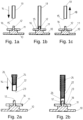
- a connecting element 12 In order to rivet a first part 10 to a second part 11, also referred to as a joining partner, a connecting element 12, also referred to as a pin or rivet, is first heated by applying a hot medium or hot air ( Fig. 1a, 1b ).
- a hot medium or hot air Fig. 1a, 1b
- the connecting element 12 is assigned to the first part 10 and guided through an opening in the second part 11.
- the principle of heating the connecting element 12 is determined by the Fig. 1a to 1c shown.
- a nozzle 13 which is essentially tubular, is guided over the connecting element 12 in the direction of the arrow 14 ( Fig. 1a, 1b ).
- the connecting element 12 can also be guided into the nozzle 13.
- the hot air to be led through the nozzle 13 is generated by a hot air generator, not shown. Air is first supplied to the hot air generator and then heated to a specified temperature. The hot air is accelerated through the nozzle 13 directly onto the connecting element 12 by a corresponding blower (not shown).
- the nozzle 13 is only guided over the connecting element 12 so far that there is between the end face 15 and one Surface 16 of the second part 11 forms a gap 17.
- Those through nozzle 13 Flowing hot air thus heats the connecting element 12 and then leaves the nozzle 13 through the ring-like gap ( Fig. 1b ).
- the nozzle 13 is again guided away from the connecting element 12 in the direction of arrow 18 ( Fig. 1c ). Furthermore, the nozzle 13 is moved in such a way that it can apply hot air to a further connecting element 12 or a further first part 10 is aligned together with the corresponding second part 11 relative to the nozzle 13 so that this can in turn be guided over the connecting element 12 .
- the components 10, 11 are transported from the station or device for heating the fastener 12 for riveting to another station or device.
- This riveting device according to the invention is shown schematically by the Figures 2a to 2e described.
- the device for riveting is preferably in connection with those in the Figures 1a to 1c , 3a to 3c and 4a to 4c
- the devices shown for heating a connecting element 12 should be considered.
- the riveting device described here can also be combined with other heating devices.
- a tubular shaft 22 is guided over the connecting element 12 ( Fig. 2a ).
- An end face 23 of the shaft 22 is placed on the surface 16 of the second part 11, so that a closed chamber is formed inside the shaft 22 ( Fig. 2b ).
- the shaft is spring-loaded in order to adapt to any irregularities on the surface 16 or to counteract vibrations.
- a mold stamp 24 is movably mounted within the shaft 22. As soon as the shaft 22 has lowered in the direction 14 over the connecting element 12, or even during this, the mold stamp 24 is also moved within the shaft 22 in the direction 14 towards the connecting element 12 ( Fig. 2c ).
- an outer diameter of the forming die 24 corresponds to an inner diameter of the shaft 22, so that no gap can form between the shaft 22 and the forming die 24.
- An end face 26 of the mold stamp 24 is concave in the exemplary embodiment shown here.
- the shape or curvature of the end face 26 later defines the shape of the deformed connecting element 12. Therefore can it can also be provided that the end face 26 shown in the figures has a different shape; for example a convex shape or a planar shape.
- the connecting element 12 is compressed or deformed by the forming stamp 24 in the direction of the arrow 14 ( Fig. 2d ).
- the still hot connecting element 12 adapts to the shape of the end face 26 of the molding die 24 and to the inner wall of the shaft 22. This restriction in the movement of the connecting element 12 sets the shape of the connecting element 12 in a defined manner.
- the force applied to the die 24 can be varied in order to deform the connecting element 12 with a defined pressure.
- the speed at which the mold stamp 24 is moved within the shaft 22 can be varied or reduced.
- Riveting can be controlled by a distance measuring device for the mold stamp 24 and/or a sensor for determining the counterpressure exerted by the connecting element 12. This control makes it possible for the mold stamp 24 to always be guided onto the connecting element 12 with the same force and the same speed under the defined conditions. This procedure allows optimal reproducibility of the application of force or the riveting process to be achieved.
- the pressure that is exerted on the connecting element 12 by the mold stamp 24 can take place via springs or a spring preload assigned to the mold stamp 24. By adjusting this spring preload, the force input through the mold stamp 24 can be adjusted.
- the shaft 22 together with the forming punch 24 are removed again from the surface 16 in the direction of the arrow 18.
- the mold stamp 24 can also move back within the shaft 22 ( Fig. 2e ).
- Fig. 3a to 3c a further device for heating a connecting means 12 is described.
- Objects of the Fig. 3a to 3c which are identical to those of the Fig. 1a to 1c are designated with the same reference numbers.
- the nozzle 13 is guided over the connecting element 12 in such a way that a gap 17 remains between the surface 16 of the second part 11 and the end face 15 of the nozzle 13.
- the connecting element 12 is guided into the nozzle 13.
- the sleeve 19 is now arranged around the nozzle 13 in such a way that a channel 20 is formed between an outer wall of the nozzle 13 and an inner wall of the sleeve 19.
- This channel 20 can extend axially in a ring-like manner around the nozzle 13 or within the sleeve 19.
- this channel 20 has any shape and deviates from a ring-like shape.
- An end face 21 of the sleeve 19 is slightly offset backwards in the direction opposite to the direction of the arrow 14. As a result, the end face 15 of the nozzle 13 and the end face 21 of the sleeve 19 are offset from one another. Thus, a distance between the end face 21 of the sleeve 19 and the surface 16 of the second part 11 is greater than a distance between the end face 15 of the nozzle 13 and the surface 16 of the second part 11 ( Fig. 3b ).
- the still hot air emerging from the end face 15 of the nozzle 13 can be sucked out through the channel 20 between the nozzle 13 and the sleeve 19.
- This suction can be done actively by a vacuum pump, not shown, which z. B. on a side of the sleeve 19 opposite the end face 21 is connected to the same.
- the hot air is passively discharged through the channel 20 due to the effect of the dynamic pressure. Through this active or passive removal of the hot air, at least a large part of the hot air emerging from the nozzle 13 can be directed away from the surface 16 and can be fed back to the hot air generator and the blower for reheating the connecting element 12.
- the unit consisting of sleeve 19 and nozzle 13 is moved away from the connecting element 12 in the direction of arrow 18 ( Fig. 3c ).
- the end face 21 of the sleeve 19 is arranged offset in the direction of the arrow 14 from the end face 15 of the nozzle 13. This offset creates a gap 17 between the end face 15 of the nozzle 13 and the surface 16, while the end face 21 of the sleeve 19 can be placed on the surface 16.
- the sleeve 19 and the nozzle 13 can be moved axially relative to one another. Due to the possibility of moving the nozzle 13 and the sleeve 19 against each other, both the exemplary embodiment can be used with the same unit Fig. 3a to 3c as well as the exemplary embodiment of the 4a to 4c will be realized. Due to a possible spring preload between the sleeve 19 and the nozzle 13, they move back to an initial position as soon as a force triggering the relative movement is switched off.
- any irregularities or unevenness on the surface 16 of the second part 11 can be compensated for when the end face 21 of the sleeve 11 is placed on the surface 16.
- the relative movement can be carried out, for example, by a drive, not shown, which is also not carried out by a drive
- the control unit shown is operated in such a way that when the unit, consisting of the nozzle 13 and the sleeve 19, is brought down, the sleeve 19 is guided over the nozzle 13.
- This control unit can also be used to check whether the sleeve 19 or the nozzle 13 has been moved back to a starting position after the connecting element 12 has been exposed to hot air.
Landscapes
- Engineering & Computer Science (AREA)
- Mechanical Engineering (AREA)
- Physics & Mathematics (AREA)
- Thermal Sciences (AREA)
- Fluid Mechanics (AREA)
- Chemical & Material Sciences (AREA)
- Combustion & Propulsion (AREA)
- Insertion Pins And Rivets (AREA)
- Pressure Welding/Diffusion-Bonding (AREA)
Description
- Die Erfindung betrifft eine Vorrichtung zum Vernieten von Bauteilen gemäß dem Oberbegriff des Anspruchs 1. Des Weiteren betrifft die Erfindung ein Verfahren zum Vernieten gemäß dem Oberbegriff des Anspruchs 7.
- Ein aus
DE 10 2016 006 097 A1 ,US 5 187 863 ,GB 2 173 139 A EP 3 002 105 A1 bekanntes Verfahren zum Verbinden von zwei Teilen bzw. Bauteilen ist das Vernieten. Dabei wird beispielsweise ein erstes Teil mit einem zweiten Teil, bzw. einem sogenannten Fügepartner, in Kontakt gebracht und durch ein Verbindungsmittel, insbesondere durch einen Pin oder einen Niet, miteinander verbunden bzw. vernietet. - Bei einem derartigen Nietverfahren ist es von äußerster Bedeutung, dass das Verbindungselement stets mit der gleichen Krafteinbringung beaufschlagt wird, um eine ausreichend starke Verbindung zwischen den beiden Teilen zu gewährleisten. Insbesondere bei einer Vielzahl von durchzuführenden Nietvorgängen von zwei Teilen, muss die Krafteinbringung reproduzierbar sein. Wenn die einzelnen Verbindungselemente von zwei Teilen, die zu verbinden sind, unterschiedliche Krafteinbringungen erfahren, kann dies zu einer mangelhaften Verbindung der Teile mit einer ungenügenden Stabilität führen.
- Davon ausgehend liegt der Erfindung die Aufgabe zugrunde, eine Vorrichtung und ein Verfahren der eingangs genannten Art zu schaffen, bei denen die genannten Nachteile beseitigt sind.
- Eine Vorrichtung zur Lösung dieser Aufgabe weist die Merkmale des Anspruchs 1 auf. Demnach ist eine Vorrichtung mit einem Formstempel und mit einem Schaft, in dem der Formstempel beweglich gelagert ist, vorgesehen. Dabei ist ein Innendurchmesser des Schaftes derart bemessen, dass er einem Durchmesser des durch den Formstempel verformten Verbindungselementes entspricht. Zum Vernieten des Verbindungselementes mit dem Fügepartner wird das Verbindungselement von dem Formstempel derart verformt, dass es an die Innenwandung des Schaftes gedrückt wird. Die Innenwandung des Schaftes stellt für das sich verformende Verbindungselement somit eine Gegenform dar. Durch diese Gegenform oder den Widerstand, den die Innenwandung des Schaftes auf das sich verformende Verbindungselement ausübt, kann ein Materialaustritt des Verbindungselementes aus der Vorrichtung zum Vernieten vermieden werden. Durch diese definierten Randbedingungen ist eine reproduzierbare Krafteinbringung durch den Formstempel auf das Verbindungselement möglich. Das Verbindungselement wird derart durch den Formstempel verformt, dass das verformte Verbindungselement stets die gleiche Form aufweist. Durch diese gleiche Verbindungselement- bzw. Nietkopfgeometrie wird für alle Verbindungen die gleiche Festigkeit erreicht. Ferner ist vorgesehen, dass der Formstempel mit einer Pneumatikeinheit verbunden ist, durch die der Formstempel mit einem steuerbaren und variierbaren, insbesondere kontinuierlichen, Druck beaufschlagbar ist, wobei der Druck vorzugsweise in Abhängigkeit von einer Temperatur des Verbindungselementes variierbar ist und wobei über die Pneumatikeinheit vorzugsweise eine Dauer der Druckbeaufschlagung des Verbindungselementes einstell- bzw. variierbar ist. Durch die temperaturabhängige Beaufschlagung des Formstempels mit einem vorbestimmbaren oder einstellbaren Druck braucht der Formstempel gerade nur mit dem Druck beaufschlagt werden, der notwendig ist, um das erhitzte Verbindungselement in die gewünschte Form zu bringen. Durch Variation der Dauer bzw. der Zeit, für die das Verbindungselement mit Druck beaufschlagt wird, kann ebenfalls die Verformung des Verbindungselementes gesteuert werden.
- Bevorzugt kann es außerdem vorgesehen sein, dass der Innendurchmesser des Schaftes mit einem Außendurchmesser des Formstempels korrespondiert, vorzugweise dass der Formstempel formschlüssig in dem Schaft bewegbar ist oder der Formstempel und eine Innenwandung des Schaftes wenigstens geringfügig voneinander beabstandet sind. Dadurch kann vermieden werden, dass Material beim Verformen des Verbindungselementes durch einen Spalt zwischen der Innenwandung des Schaftes und dem Formstempel tritt. Dies führt zu einer reproduzierbaren Krafteinbringung durch den Formstempel.
- Darüber hinaus kann es erfindungsgemäß vorgesehen sein, dass die Vorrichtung ein Schnellwechselsystem aufweist, durch welches der Schaft und/oder der Formstempel und sämtliche mechanische, elektrische und/oder pneumatische Verbindungen miteinander koppel- und entkoppelbar sind. Durch dieses Schnellwechselsystem kann zum einen die Wartung der Vorrichtung schneller und einfacher gestaltet werden und zum anderen können für das Verbinden verschiedener Teile bzw. das Vernieten von verschiedenen Verbindungselementen auf eine schnelle und einfache Art und Weise entsprechende Schafte und Formstempel ausgetauscht werden. Für die Kopplung der einzelnen Verbindungen können die gängigen Schnellverschlüsse, wie beispielsweise Bajonettverschlüsse, eingesetzt werden.
- Ein weiteres bevorzugtes Ausführungsbeispiel kann es vorsehen, dass dem Formstempel ein Temperaturregelsystem zugeordnet ist zur Erwärmung oder Kühlung des Formstempels, insbesondere, dass ein Träger des Formstempels Kanäle zur Führung eines Kühl- oder Heizmediums, vorzugweise Luft, aufweist, und der Formstempel und/oder der Schaft über mindestens einen Temperatursensor verfügt, der dem Temperaturregelsystem zugeordnet ist. Durch das Temperaturregelsystem lässt sich insbesondere das erhitzte Verbindungselement schneller abkühlen. Gleichermaßen ist es denkbar, dass der Formstempel zusätzlich erhitzt wird, um ein Trennen des Formstempels von dem Verbindungselement zu erleichtern.
- Dazu kann es des Weiteren vorgesehen sein, dass der Formstempel eine Antihaftbeschichtung aufweist. Durch diese Antihaftbeschichtung wird zum einen der Formstempel geschützt, was zu einer Verlängerung der Standzeit führt. Des Weiteren kann durch eine derartige Beschichtung das Ablöseverhalten des Formstempels von dem Verbindungselement verbessert werden. Schließlich kann durch eine entsprechende Antihaftbeschichtung auch die Oberflächenbeschaffenheit des Verbindungselementes verbessert werden, was insbesondere zu ästhetischen Vorteilen führt.
- Darüber hinaus kann es ein weiteres vorteilhaftes Ausführungsbeispiel der Erfindung vorsehen, dass sowohl der Formstempel als auch der Schaft über eine Positionsbestimmungseinrichtung verfügen, mit welcher der Hub des Formstempels und des Schaftes über einer Oberfläche des zweiten Teils und über dem Verbindungselement sowie die relative Ausrichtung des Formstempels zum Schaft bestimmbar ist. Durch eine derartige Positionsbestimmungseinrichtung lässt sich die Vorrichtung automatisiert direkt über das zu verformende Verbindungselement bewegen bzw. lässt sich das Verbindungselement direkt unter den Schaft der Vorrichtung verfahren. Durch eine Ermittlung der relativen Position des Formstempels in dem Schaft erkennt eine Steuereinrichtung den durchzuführenden Hubweg für den Formstempel, um aus dem Schaft herausgefahren zu werden bzw. wird der zu fahrende Weg erkannt, der notwendig ist, um das Verbindungselement zu verformen.
- Ein weiteres Ausführungsbeispiel kann es vorsehen, dass der Vorrichtung ein Sensor zur Ermittlung einer Kennung des verwendeten Formstempels zugeordnet ist, wobei es sich bei der Kennung um einen RFID-Chip, eine Beschriftung oder ein Barcode, der dem Formstempel zugeordnet ist, handeln kann. Über eine Steuereinheit kann die Kennung des Formstempels dokumentiert werden. Darüber hinaus kann es vorgesehen sein, dass für die Kennung eines jeden Formstempels eine Kalibrierung hinterlegt ist, mit der die Vorrichtung bzw. der Formstempel vor dem Vernieten kalibrierbar ist.
- Ein Verfahren zur Lösung der eingangs genannten Aufgabe wird durch die Maßnahmen des Anspruchs 7 beschrieben. Demnach ist es vorgesehen, dass ein Verbindungselement zunächst in einer Vorrichtung zum Erhitzen erhitzt wird, anschließend zu einer Vorrichtung zum Vernieten transportiert und dort durch einen Formstempel verformt wird. Alternativ ist es auch denkbar, dass die Vorrichtung zum Vernieten dem erhitzten Verbindungselement zugeführt wird. Die Vorrichtung zum Vernieten und die Vorrichtung zum Erhitzen sind bei beiden Alternativen räumlich voneinander getrennt.
- Zum Vernieten des Verbindungselementes wird ein rohrartiger, den Formstempel führender Schaft über das Verbindungselement geführt und mit einer Stirnseite auf einer Oberfläche des zweiten Teils abgesetzt. Es ist auch denkbar, dass das Verbindungselement in den den Formstempel führenden Schaft geführt wird. Weiter ist es vorgesehen, dass der Formstempel in dem Schaft zum Vernieten der Teile auf das Verbindungselement zubewegt wird, wobei das Verbindungselement durch den Formstempel so lange verformt wird, bis ein äußerer Durchmesser des verformten Verbindungselementes einem Innendurchmesser des Schaftes entspricht. Somit wird dadurch, dass die Stirnseite des Schaftes auf der Oberfläche des zweiten Teils abgesetzt wird, eine Begrenzung für das sich verformende Verbindungselement geschaffen. Dadurch wird erreicht, dass die Geometrie der verformten Verbindungselemente stets gleich ist. Außerdem kann dadurch gewährleistet werden, dass die Krafteinbringung auf alle Verbindungselemente identisch bzw. reproduzierbar ist, da das sich verformende Verbindungselement nicht weiter verformt werden kann.
- Darüber hinaus kann es ein weiteres Ausführungsbeispiel der Erfindung vorsehen, dass der Formstempel mit einem Druck beaufschlagt wird, der insbesondere in Abhängigkeit von einer ermittelten Temperatur des Verbindungselementes variiert wird. So kann beispielsweise der für die Verformung des Verbindungselementes notwendige Druck bei einer erhöhten Temperatur des Verbindungselementes geringer sein, als bei einer geringeren Temperatur.
- Gleichermaßen kann es erfindungsgemäß vorgesehen sein, dass die Temperatur des Formstempels durch mindestens einen Temperatursensor gemessen wird und durch ein Temperaturregelsystem der Formstempel gekühlt oder erhitzt wird.
- Außerdem kann es erfindungsgemäß vorgesehen sein, dass eine Position des Formstempels und des Schaftes relativ zum Verbindungselement und eine Position des Formstempels relativ zum Schaft durch eine Positionsbestimmungseinrichtung ermittelt werden und der Formstempel und der Schaft in Abhängigkeit von diesen ermittelten Positionen verfahren werden. Insbesondere werden der Formstempel und der Schaft zu einem nächsten Verbindungselement verfahren.
- Ein bevorzugtes Ausführungsbeispiel der vorliegenden Erfindung wird nachfolgend anhand der Zeichnung näher erläutert. In dieser zeigt:
- Fig. 1a
- Heranführen einer Düse an ein Verbindungselement,
- Fig. 1b
- Absenken der Düse über dem Verbindungselement zur Beaufschlagung mit Heißluft,
- Fig. 1c
- Wegbewegen der Düse von dem erhitzten Verbindungselement,
- Fig. 2a
- Heranführen einer Vorrichtung zum Vernieten an das Verbindungselement,
- Fig. 2b
- Absetzen eines Schaftes auf einer Oberfläche,
- Fig. 2c
- Verformung des Verbindungselementes durch einen Formstempel,
- Fig. 2d
- Ausformung des Verbindungselementes durch den Formstempel,
- Fig. 2e
- Wegbewegen der Vorrichtung zum Nieten von den vernieteten Teilen,
- Fig. 3a
- ein weiteres Ausführungsbeispiel für das Heranführen einer Düse mit einer Hülse an ein Verbindungselement,
- Fig. 3b
- Beaufschlagung des Verbindungselementes mit Heißluft durch die Düse,
- Fig. 3c
- Wegbewegen der Düse und der Hülse nach Erhitzen des Verbindungselementes,
- Fig. 4a
- eine Darstellung eines weiteren Ausführungsbeispiels für ein Heranführen einer Düse mit einer Hülse an ein Verbindungselement,
- Fig. 4b
- Beaufschlagung des Verbindungselementes mit Heißluft durch die Düse, und
- Fig. 4c
- Wegbewegen der Hülse und der Düse von dem Verbindungselement.
- Um ein erstes Teil 10 mit einem zweiten Teil 11, auch als Fügepartner bezeichnet, zu vernieten, wird ein Verbindungselement 12, auch als Pin oder Niet bezeichnet, zunächst durch Beaufschlagung eines heißen Mediums bzw. Heißluft erhitzt (
Fig. 1a, 1b ). Bei dem in den Figuren dargestellten Ausführungsbeispiel ist das Verbindungselement 12 dem ersten Teil 10 zugeordnet und durch eine Öffnung in dem zweiten Teil 11 geführt. - Das Prinzip des Erhitzens des Verbindungselementes 12 wird durch die
Fig. 1a bis 1c dargestellt. Dabei wird zunächst eine Düse 13, die im Wesentlichen rohrartig ausgebildet ist, in Pfeilrichtung 14 über das Verbindungselement 12 geführt (Fig. 1a, 1b ). Der Übersicht halber ist hier nur ein Teil der stark schematisierten Düse 13 dargestellt. Gleichermaßen kann das Verbindungselement 12 auch in die Düse 13 geführt werden. Die durch die Düse 13 zu führende Heißluft wird durch einen nicht dargestellten Heißluftgenerator erzeugt. Dabei wird dem Heißluftgenerator zunächst Luft zugeführt und diese sodann auf eine vorzugebende Temperatur erhitzt. Durch ein entsprechendes nicht dargestelltes Gebläse wird die Heißluft beschleunigt durch die Düse 13 direkt auf das Verbindungselement 12 geführt. Damit die Heißluft an einer Stirnseite 15 der Düse 13 beim Erhitzen des Verbindungselementes 12 entweichen kann und es nicht zu einem Aufstauen der heißen Luft kommt, wird die Düse 13 gerade nur so weit über das Verbindungselement 12 geführt, dass sich zwischen der Stirnseite 15 und einer Oberfläche 16 des zweiten Teils 11 ein Spalt 17 ausbildet. Die durch die Düse 13 strömende Heißluft erhitzt somit das Verbindungselement 12 und verlässt sodann die Düse 13 durch den ringartigen Spalt (Fig. 1b ). - Nach einer vorgegebenen Zeit, in der das Verbindungselement 12 ausreichend mit der Heißluft beaufschlagt wurde, wird die Düse 13 wieder in Pfeilrichtung 18 von dem Verbindungselement 12 weggeführt (
Fig. 1c ). Im Weiteren wird die Düse 13 derart verfahren, dass sie ein weiteres Verbindungselement 12 mit Heißluft beaufschlagen kann bzw. wird ein weiteres erstes Teil 10 zusammen mit dem entsprechenden zweiten Teil 11 relativ zu der Düse 13 ausgerichtet, damit diese wiederum über das Verbindungselement 12 führbar ist. - Sobald das Verbindungselement 12 erhitzt wurde, werden die Bauteile 10, 11 von der Station oder der Vorrichtung zum Erhitzen des Verbindungselements 12 für das Nieten zu einer weiteren Station oder Vorrichtung transportiert. Diese erfindungsgemäße Vorrichtung zum Nieten wird schematisch durch die
Figuren 2a bis 2e beschrieben. Die Vorrichtung zum Nieten ist vorzugsweise im Zusammenhang mit den in denFiguren 1a bis 1c ,3a bis 3c und 4a bis 4c dargestellten Vorrichtungen zum Erhitzen eines Verbindungselements 12 zu betrachten. Allerdings kann die hier beschriebene Vorrichtung zum Nieten auch mit anderen Heizvorrichtungen kombiniert werden. - Zum erfindungsgemäßen Vernieten des ersten Teils 10 mit dem zweiten Teil 11 wird ein rohrartiger Schaft 22 über das Verbindungselement 12 geführt (
Fig. 2a ). Dabei wird eine Stirnseite 23 des Schaftes 22 auf die Oberfläche 16 des zweiten Teils 11 abgesetzt, sodass sich eine geschlossene Kammer im Inneren des Schaftes 22 ausbildet (Fig. 2b ). Für eine formschlüssige Verbindung ist es denkbar, dass der Schaft federvorgespannt ist, um sich eventuellen Unregelmäßigkeiten auf der Oberfläche 16 anzupassen oder um Vibrationen entgegenzuwirken. Innerhalb des Schaftes 22 ist ein Formstempel 24 beweglich gelagert. Sobald sich der Schaft 22 in Richtung 14 über das Verbindungselement 12 gesenkt hat, oder auch währenddessen, wird der Formstempel 24 innerhalb des Schaftes 22 ebenfalls in Richtung 14 auf das Verbindungselement 12 zubewegt (Fig. 2c ). Bevorzugterweise entspricht ein Außendurchmesser des Formstempels 24 einem Innendurchmesser des Schaftes 22, sodass sich zwischen dem Schaft 22 und dem Formstempel 24 kein Spalt ausbilden kann. - Eine Stirnfläche 26 des Formstempels 24 ist bei dem hier dargestellten Ausführungsbeispiel konkav ausgebildet. Durch die Form bzw. Wölbung der Stirnfläche 26 wird später die Form des verformten Verbindungselementes 12 definiert. Daher kann es auch vorgesehen sein, dass die in den Figuren dargestellte Stirnfläche 26 eine andere Form aufweist; beispielsweise eine konvexe Form oder eine plane Form.
- Zum Vernieten des ersten Teils 10 mit dem zweiten Teil 11 wird das Verbindungselement 12 durch den Formstempel 24 in Pfeilrichtung 14 zusammengedrückt bzw. verformt (
Fig. 2d ). Dabei fügt sich das immer noch heiße Verbindungselement 12 an die Form der Stirnfläche 26 des Formstempels 24 und an die Innenwandung des Schaftes 22 an. Durch diese Einschränkung in der Bewegung des Verbindungselementes 12 wird die Form des Verbindungselementes 12 auf eine definierte Art und Weise festgelegt. - Sobald die Stirnfläche 26 des Formstempels 24 in Kontakt mit dem Verbindungselement 12 gelangt, kann die Kraft, mit der der Formstempel 24 beaufschlagt wird, variiert werden, um das Verbindungselement 12 mit einem definierten Druck zu verformen. Gleichermaßen kann die Geschwindigkeit mit der der Formstempel 24 innerhalb des Schaftes 22 bewegt wird, variiert bzw. reduziert werden.
- Durch eine Wegmesseinrichtung für den Formstempel 24 und/oder einen Sensor zur Ermittlung des durch das Verbindungselement 12 ausgeübten Gegendrucks kann das Vernieten gesteuert werden. Durch diese Steuerung ist es möglich, dass der Formstempel 24 unter den definierten Bedingungen stets mit der gleichen Kraft und der gleichen Geschwindigkeit auf das Verbindungselement 12 geführt wird. Durch dieses Vorgehen kann eine optimale Reproduzierbarkeit der Krafteinbringung bzw. des Nietvorgangs erzielt werden. Der Druck, der durch den Formstempel 24 auf das Verbindungselement 12 ausgeübt wird, kann über dem Formstempel 24 zugeordnete Federn bzw. eine Federvorspannung erfolgen. Durch Einstellung dieser Federvorspannung kann der Krafteintrag durch den Formstempel 24 eingestellt werden.
- Sobald der Nietvorgang abgeschlossen ist, d. h., das Verbindungselement 12 seine vorgesehene Form erreicht hat bzw. mit einer vordefinierten Kraft beaufschlagt wurde, wird der Schaft 22 mitsamt der Formstempel 24 wieder von der Oberfläche 16 in Pfeilrichtung 18 entfernt. Bei diesem Zurückbewegen kann sich der Formstempel 24 auch innerhalb des Schaftes 22 bereits zurückbewegen (
Fig. 2e ). - Durch die Figuren
Fig. 3a bis 3c wird eine weitere Vorrichtung zum Erhitzen eines Verbindungsmittels 12 beschrieben. Bei diesem Ausführungsbeispiel ist die in denFig. 1a bis 1c dargestellte Düse 13 durch eine Hülse 19 ergänzt. Gegenstände derFig. 3a bis 3c , die identisch zu denen derFig. 1a bis 1c sind, werden mit gleichen Bezugsziffern bezeichnet. - Genau wie zuvor anhand der
Fig. 1a bis 1c beschrieben, wird zum Erhitzen des Verbindungselementes 12 die Düse 13 über das Verbindungselement 12 geführt und zwar derart, dass zwischen der Oberfläche 16 des zweiten Teils 11 und der Stirnseite 15 der Düse 13 ein Spalt 17 verbleibt. Es ist jedoch genauso denkbar, dass das Verbindungselement 12 in die Düse 13 hineingeführt wird. Um die Düse 13 ist nun die Hülse 19 angeordnet, und zwar derart, dass sich zwischen einer Außenwandung der Düse 13 und einer Innenwandung der Hülse 19 ein Kanal 20 ausbildet. Dieser Kanal 20 kann sich ringartig axial um die Düse 13 bzw. innerhalb der Hülse 19 erstrecken. Es kann jedoch auch vorgesehen sein, dass dieser Kanal 20 eine beliebige Form aufweist und von einer ringartigen Gestalt abweicht. - Eine Stirnseite 21 der Hülse 19 ist leicht entgegen der Pfeilrichtung 14 nach hinten versetzt. Dadurch sind die Stirnseite 15 der Düse 13 und die Stirnseite 21 der Hülse 19 voneinander versetzt. Somit ist ein Abstand zwischen der Stirnseite 21 der Hülse 19 und der Oberfläche 16 des zweiten Teils 11 größer als ein Abstand zwischen der Stirnseite 15 der Düse 13 und der Oberfläche 16 des zweiten Teils 11 (
Fig. 3b ). - Wenn nun das Verbindungselement 12 mit Heißluft beaufschlagt wird, kann die aus der Stirnseite 15 der Düse 13 heraustretende immer noch heiße Luft durch den Kanal 20 zwischen der Düse 13 und der Hülse 19 abgesogen werden. Dieses Absaugen kann aktiv durch eine nicht dargestellte Vakuumpumpe erfolgen, welche z. B. an einer der Stirnseite 21 gegenüberliegenden Seite der Hülse 19 mit selbiger verbunden ist. Außerdem ist es denkbar, dass die Heißluft passiv durch den Effekt des Staudruckes durch den Kanal 20 abgeführt wird. Durch dieses aktive oder passive Abführen der Heißluft kann wenigstens ein Großteil der aus der Düse 13 heraustretenden Heißluft zum einen von der Oberfläche 16 weggeleitet werden und zum anderen dem Heißluftgenerator sowie dem Gebläse zum erneuten Erhitzen des Verbindungselementes 12 wieder zugeführt werden.
- Sobald das Verbindungselement 12 ausreichend mit Heißluft beaufschlagt wurde, wird die Einheit bestehend aus Hülse 19 und Düse 13 in Pfeilrichtung 18 von dem Verbindungselement 12 wegbewegt (
Fig. 3c ). - Bei dem in den
Fig. 4a bis 4c dargestellten Ausführungsbeispiel der Erfindung besteht ein wesentlicher Unterschied zu dem in denFig. 3a bis 3c dargestellten Ausführungsbeispiel darin, dass während der Beaufschlagung des Verbindungselementes 12 mit Heißluft die Stirnseite 21 der Hülse 19 in Kontakt mit der Oberfläche 16 des zweiten Teils 11 gebracht ist (Fig. 4b ). Ansonsten verhält sich das in denFig. 4a bis 4c dargestellte Ausführungsbeispiel ähnlich zu dem in denFig. 3a bis 3c dargestellten Ausführungsbeispiel, weswegen für gleiche Gegenstände gleiche Bezugszeichen verwendet werden. - Dadurch, dass die Hülse 19 mit ihrer Stirnseite 21 auf der Oberfläche 16 des zweiten Teils 11 aufliegt, wird die gesamte Heißluft, die durch die Stirnseite 15 der Düse 13 in den Kanal 20 tritt, abgesaugt (
Fig. 3b ). Auf diese Weise kann die gesamte Heißluft für die Erhitzung des Verbindungselementes 12 wiederverwendet werden. Des Weiteren kann durch diese Bildung einer geschlossenen Kammer um die Düse 13 das Verbindungselement 12 erhitzt werden, ohne dass die umliegenden Teile, insbesondere das zweite Teil 11 oder empfindlichen Bauteile, einer zu hohen Hitze ausgesetzt werden. - Bei dem in den
Fig. 4a bis 4c dargestellten Ausführungsbeispiel kann es vorgesehen sein, dass die Stirnseite 21 der Hülse 19 in Pfeilrichtung 14 versetzt zu der Stirnseite 15 der Düse 13 angeordnet ist. Durch diesen Versatz bildet sich zwischen der Stirnseite 15 der Düse 13 und der Oberfläche 16 ein Spalt 17 aus, während die Stirnseite 21 der Hülse 19 auf der Oberfläche 16 absetzbar ist. - Außerdem kann es vorgesehen sein, dass die Hülse 19 und die Düse 13 axial zueinander verfahrbar sind. Durch die Möglichkeit, die Düse 13 und die Hülse 19 gegeneinander zu verfahren, kann mit der gleichen Einheit sowohl das Ausführungsbeispiel der
Fig. 3a bis 3c sowie das Ausführungsbeispiel derFig. 4a bis 4c realisiert werden. Durch eine eventuelle Federvorspannung zwischen der Hülse 19 und der Düse 13 bewegen sich diese zurück in eine Ausgangslage, sobald eine die relative Bewegung auslösende Kraft abgeschaltet wird. Durch die Federvorspannung oder eine federnde Lagerung der Hülse 19 oder der Düse 13 können eventuelle Unregelmäßigkeiten oder Unebenheiten auf der Oberfläche 16 des zweiten Teils 11 beim Aufsetzen der Stirnseite 21 der Hülse 11 auf die Oberfläche 16 ausgeglichen werden. Durch die federnde Lagerung der Hülse 19 oder durch eine Federvorspannung der Hülse 19 kann somit trotz eventueller Unregelmäßigkeiten oder Unebenheiten eine wenigstens weitestgehend bündige Verbindung zwischen Hülse 19 und Oberfläche 16 erreicht werden. Auch eventuelle Vibrationen der Vorrichtung oder des zweiten Teils 11 können durch die federnde Lagerung der Hülse 19 ausgeglichen werden. Die relative Bewegung kann beispielsweise durch einen nicht dargestellten Antrieb erfolgen, der durch eine ebenfalls nicht dargestellte Steuereinheit derart betrieben wird, dass beim Herabführen der Einheit, bestehend aus der Düse 13 und der Hülse 19, die Hülse 19 über die Düse 13 hinweg geführt wird. Durch diese Steuereinheit kann ebenfalls kontrolliert werden, ob nach der Beaufschlagung des Verbindungselementes 12 mit Heißluft die Hülse 19 bzw. die Düse 13 wieder in eine Ausgangslage zurückbewegt wurde. -
- 10
- erstes Teil
- 11
- zweites Teil
- 12
- Verbindungselement
- 13
- Düse
- 14
- Pfeilrichtung
- 15
- Stirnseite
- 16
- Oberfläche
- 17
- Spalt
- 18
- Pfeilrichtung
- 19
- Hülse
- 20
- Kanal
- 21
- Stirnseite
- 22
- Schaft
- 23
- Stirnseite
- 24
- Formstempel
- 26
- Stirnfläche
Claims (12)
- Vorrichtung mit einem Formstempel zum Vernieten eines ersten Teils (10) mit einem zweiten Teil (11), insbesondere einem Fügepartner, wobei dem ersten Teil (10) ein erhitztes Verbindungselement (12) zuordbar ist, das der Verbindung des ersten Teils (10) mit dem zweiten Teil (11) dient, und mit einem Schaft (22), in dem der Formstempel (24) beweglich gelagert ist, und wobei ein Innendurchmesser des Schafts (22) einem Durchmesser des durch den Formstempel (24) verformten Verbindungselementes (12) entspricht, dadurch gekennzeichnet, dass der Formstempel (24) mit einer Pneumatikeinheit verbunden ist, durch die der Formstempel (24) mit einem steuerbaren und variierbaren, insbesondere kontinuierlichen, Druck beaufschlagbar ist, wobei der Druck vorzugsweise in Abhängigkeit von einer Temperatur des Verbindungselementes (12) variierbar ist und wobei über die Pneumatikeinheit vorzugsweise eine Dauer der Druckbeaufschlagung des Verbindungselementes (12) einstell- bzw. variierbar ist.
- Vorrichtung nach Anspruch 1, dadurch gekennzeichnet, dass der Innendurchmesser des Schafts (22) mit einem Außendurchmesser des Formstempels (24) korrespondiert, vorzugsweise dass der Formstempel (24) formschlüssig in dem Schaft (22) bewegbar ist oder der Formstempel (24) und eine Innenwandung des Schaftes (22) wenigstens geringfügig voneinander beabstandet sind.
- Vorrichtung nach einem der vorherigen Ansprüche gekennzeichnet durch ein Schnellwechselsystem, durch welches der Schaft (22) und/oder der Formstempel (24) und sämtliche mechanische, elektrische und/oder pneumatische Verbindungen miteinander koppel- und entkoppelbar sind.
- Vorrichtung nach einem der vorherigen Ansprüche, dadurch gekennzeichnet, dass dem Formstempel (24) ein Temperaturregelsystem zugeordnet ist zur Erwärmung oder Kühlung des Formstempels (24), insbesondere dass ein Träger des Formstempels (24) Kanäle zur Führung eines Kühl- oder Heizmediums, vorzugsweise Luft, aufweist, und der Formstempel (24) und/oder der Schaft (22) über mindestens einen Temperatursensor verfügt, der dem Temperaturregelsystem zugeordnet ist.
- Vorrichtung nach einem der vorherigen Ansprüche, dadurch gekennzeichnet, dass sowohl der Formstempel (24) als auch der Schaft (22) über eine Positionsbestimmungseinrichtung verfügen, mit welcher der Hub des Formstempels (24) und des Schafts (22) über einer Oberfläche (16) des zweiten Teils (11) und über dem Verbindungselement (12) sowie die relative Ausrichtung des Formstempels (24) zum Schaft (22) bestimmbar sind.
- Vorrichtung nach einem der vorherigen Ansprüche gekennzeichnet durch einen Sensor zur Ermittlung einer Kennung des verwendeten Formstempels (24), vorzugsweise eines RFID-Chips oder eine Beschriftung des Formstempels (24), und eine Steuereinheit welche die ermittelte Kennung zur Dokumentation speichert und/oder mit einer hinterlegten Kennung, insbesondere für eine Kalibrierung, abgleicht.
- Verfahren zum Vernieten eines ersten Teils (10) mit einem zweiten Teil (11), insbesondere einem Fügepartner, wobei ein Verbindungselement (12) zum Verbinden des ersten Teils (10) mit dem zweiten Teil (11) vor dem Vernieten erhitzt wird, und wobei das Verbindungselement (12) zunächst in einer Vorrichtung zum Erhitzen erhitzt wird und anschließend in einer Vorrichtung zum Vernieten durch einen Formstempel (24) verformt wird, dadurch gekennzeichnet, dass der Formstempel (24) mit einer Pneumatikeinheit verbunden ist, durch die der Formstempel (24) mit einem steuerbaren und variierbaren, insbesondere kontinuierlichen, Druck beaufschlagt wird, wobei der Druck vorzugsweise in Abhängigkeit von einer Temperatur des Verbindungselementes (12) variiert wird und wobei über die Pneumatikeinheit vorzugsweise eine Dauer der Druckbeaufschlagung des Verbindungselementes (12) eingestellt bzw. variiert wird.
- Verfahren nach Anspruch 7, dadurch gekennzeichnet, dass zum Vernieten ein rohrartiger den Formstempel (24) führender Schaft (22) über das Verbindungselement (12) geführt und mit einer Stirnseite (23) auf einer Oberfläche (16) des zweiten Teils (11) abgesetzt wird.
- Verfahren nach Anspruch 8, dadurch gekennzeichnet, dass der Formstempel (24) in dem Schaft (22) zum Vernieten der Teile (10, 11) auf das Verbindungselement (12) zu bewegt wird, wobei das Verbindungselement (12) durch den Formstempel (24) so lange verformt wird bis ein äußerer Durchmesser des verformten Verbindungselements (12) einem Innendurchmesser des Schaftes (22) entspricht.
- Verfahren nach einem der Ansprüche 7 bis 9, dadurch gekennzeichnet, dass der Formstempel (24) mit einem Druck beaufschlagt wird, der insbesondere in Abhängigkeit von einer ermittelten Temperatur des Verbindungselements (12) variiert wird.
- Verfahren nach einem der Ansprüche 7 bis 10, dadurch gekennzeichnet, dass die Temperatur des Formstempels (24) durch mindestens einen Temperatursensor gemessen wird und durch ein Temperaturregelsystem der Formstempel (24) gekühlt oder erhitzt wird.
- Verfahren nach einem der Ansprüche 7 bis 11, dadurch gekennzeichnet, dass eine Position des Formstempels (24) und des Schafts (22) relativ zum Verbindungselement (12) und eine Position des Formstempels (24) relativ zum Schaft (22) durch eine Positionsbestimmungseinrichtung ermittelt werden und der Formstempel (24) und der Schaft (22) in Abhängigkeit von diesen ermittelten Positionen verfahren werden, insbesondere dass der Formstempel (24) und der Schaft (22) zu einem nächsten Verbindungselement (12) oder gegeneinander verfahren werden.
Applications Claiming Priority (2)
| Application Number | Priority Date | Filing Date | Title |
|---|---|---|---|
| DE102018002085.2A DE102018002085A1 (de) | 2018-03-15 | 2018-03-15 | Verfahren und Vorrichtung zum Vernieten von Bauteilen |
| PCT/EP2019/056182 WO2019175190A1 (de) | 2018-03-15 | 2019-03-12 | Verfahren und vorrichtung zum vernieten von bauteilen |
Publications (3)
| Publication Number | Publication Date |
|---|---|
| EP3765275A1 EP3765275A1 (de) | 2021-01-20 |
| EP3765275C0 EP3765275C0 (de) | 2024-01-03 |
| EP3765275B1 true EP3765275B1 (de) | 2024-01-03 |
Family
ID=65802069
Family Applications (1)
| Application Number | Title | Priority Date | Filing Date |
|---|---|---|---|
| EP19711300.4A Active EP3765275B1 (de) | 2018-03-15 | 2019-03-12 | Verfahren und vorrichtung zum vernieten von bauteilen |
Country Status (6)
| Country | Link |
|---|---|
| EP (1) | EP3765275B1 (de) |
| CN (1) | CN111867815B (de) |
| DE (1) | DE102018002085A1 (de) |
| ES (1) | ES2974798T3 (de) |
| TW (1) | TWI789505B (de) |
| WO (1) | WO2019175190A1 (de) |
Families Citing this family (1)
| Publication number | Priority date | Publication date | Assignee | Title |
|---|---|---|---|---|
| CN113059817B (zh) * | 2021-04-26 | 2025-07-18 | 三康(成都)机械设备有限责任公司 | 一种铆接方法及其铆接装置 |
Family Cites Families (9)
| Publication number | Priority date | Publication date | Assignee | Title |
|---|---|---|---|---|
| US4633559A (en) * | 1985-03-18 | 1987-01-06 | Michael Ladney | Apparatus for staking |
| NL9100546A (nl) * | 1991-03-27 | 1992-10-16 | Du Pont Nederland | Werkwijze alsmede inrichting voor het verbinden van een connector aan een plaat. |
| JP3421075B2 (ja) * | 1993-03-24 | 2003-06-30 | 日本発条株式会社 | 熱可塑性樹脂部材のかしめ方法及び締結体 |
| DE10310828A1 (de) * | 2003-03-08 | 2004-09-16 | Dieter Krumpe | Heißlufteinheit/Wärmetauscher zum schnellen Bearbeiten von Kunststoffen |
| KR100877721B1 (ko) * | 2007-11-05 | 2009-01-07 | (주)건양트루넷 | 리벳팅장치 |
| JP2015186870A (ja) * | 2014-03-27 | 2015-10-29 | トヨタ自動車株式会社 | 接合方法 |
| DE102014114379A1 (de) * | 2014-10-02 | 2016-04-07 | Sonotronic Nagel Gmbh | Nietvorrichtung und Verfahren zu seiner Anwendung |
| US10099423B2 (en) * | 2015-02-28 | 2018-10-16 | GM Global Technology Operations LLC | Methods for joining components by heat staking |
| DE102016006097A1 (de) * | 2016-05-20 | 2017-11-23 | Wolf Produktionssysteme GmbH & Co. KG | Vorrichtung zur Erzeugung des Kopfes einer Kunststoffniet sowie Verfahren hierfür |
-
2018
- 2018-03-15 DE DE102018002085.2A patent/DE102018002085A1/de not_active Withdrawn
-
2019
- 2019-03-12 ES ES19711300T patent/ES2974798T3/es active Active
- 2019-03-12 CN CN201980019292.4A patent/CN111867815B/zh active Active
- 2019-03-12 EP EP19711300.4A patent/EP3765275B1/de active Active
- 2019-03-12 WO PCT/EP2019/056182 patent/WO2019175190A1/de not_active Ceased
- 2019-03-15 TW TW108108933A patent/TWI789505B/zh active
Also Published As
| Publication number | Publication date |
|---|---|
| EP3765275C0 (de) | 2024-01-03 |
| CN111867815B (zh) | 2023-04-18 |
| CN111867815A (zh) | 2020-10-30 |
| WO2019175190A1 (de) | 2019-09-19 |
| DE102018002085A1 (de) | 2019-09-19 |
| ES2974798T3 (es) | 2024-07-01 |
| TWI789505B (zh) | 2023-01-11 |
| EP3765275A1 (de) | 2021-01-20 |
| TW201940262A (zh) | 2019-10-16 |
Similar Documents
| Publication | Publication Date | Title |
|---|---|---|
| DE10038158B4 (de) | Verfahren und Vorrichtung zum Verbinden von Gegenständen mittels plastisch verformbarer Verbindungskörper | |
| DE3608875A1 (de) | Verfahren und vorrichtung zum vernieten | |
| DE8007086U1 (de) | Vorrichtung zum formen von behaeltnissen aus einer folie | |
| DE102016101945B4 (de) | Heißnietstempel und Heißnietvorrichtung | |
| EP3369554A1 (de) | Verfahren zum ausformen von näpfen in einer erwärmten folienbahn | |
| EP0280204B1 (de) | Verfahren und Vorrichtung zum Anformen eines Flansches an einem Hohlkörper aus thermoplastischem Kunststoff | |
| DE4101545A1 (de) | Vorrichtung zur verbindung zweier bauteile mittels ultraschall | |
| DE102016006097A1 (de) | Vorrichtung zur Erzeugung des Kopfes einer Kunststoffniet sowie Verfahren hierfür | |
| DE102005039214A1 (de) | Verfahren zum Verbinden des Stoß von Dichtungsprofilen sowie Vorrichtung zu dessen Durchführung | |
| EP3186063B1 (de) | System zur weiterbehandlung von mittels spritzgiessen hergestellter vorformlinge | |
| EP2585276A1 (de) | Verfahren und vorrichtung zur herstellung eines bauteils | |
| DE102016001401A1 (de) | Verfahren und Vorrichtung zum Herstellen von Verbindungsbereichen an Faser-Matrix-Verbund-Bauteilen | |
| DE10019300A1 (de) | Verfahren und Vorrichtung zum Schweißen oder Verformen von Kunsttoffteilen | |
| DE19918516C2 (de) | Verfahren zum Verbinden mindestens zweier flächiger Bauteile | |
| EP0767760B1 (de) | Verfahren zur herstellung von glasformlingen nach dem pressverfahren sowie zur anwendung des verfahrens besonders geeignete vorrichtung | |
| EP3765275A1 (de) | Verfahren und vorrichtung zum vernieten von bauteilen | |
| EP1171252B1 (de) | Verfahren zur massivumformung von axial-symmetrischen metallischen bauteilen | |
| EP3765274B1 (de) | Verfahren und system mit einer vorrichtung zum erhitzen eines verbindungselementes | |
| DE69419206T2 (de) | Verfahren und Vorrichtung zum Herstellen eines metallischen Teils | |
| CH716048A2 (de) | Verfahren sowie eine Messeinrichtung zum Ausmessen bzw. Kalibrieren von Utensilien insbesondere bei Pressen. | |
| DE102004046516B4 (de) | Vorrichtung für das und Verfahren zum Umformen und Verbinden von Bauteilen aus thermoplastischem Kunststoff | |
| EP4052889A1 (de) | Nietverfahren und nietvorrichtung für nietdome aus kunststoff | |
| EP1960180A1 (de) | Nachbehandlungsverfahren sowie vorrichtung hierfür | |
| EP3700692A1 (de) | Mehrstufenpresse und verfahren zur herstellung eines umformteils | |
| DE102004059638B3 (de) | Vorrichtung und Verfahren zum Erzeugen einer Profilierung an einem Befestigungselement |
Legal Events
| Date | Code | Title | Description |
|---|---|---|---|
| STAA | Information on the status of an ep patent application or granted ep patent |
Free format text: STATUS: UNKNOWN |
|
| STAA | Information on the status of an ep patent application or granted ep patent |
Free format text: STATUS: THE INTERNATIONAL PUBLICATION HAS BEEN MADE |
|
| PUAI | Public reference made under article 153(3) epc to a published international application that has entered the european phase |
Free format text: ORIGINAL CODE: 0009012 |
|
| STAA | Information on the status of an ep patent application or granted ep patent |
Free format text: STATUS: REQUEST FOR EXAMINATION WAS MADE |
|
| 17P | Request for examination filed |
Effective date: 20200901 |
|
| AK | Designated contracting states |
Kind code of ref document: A1 Designated state(s): AL AT BE BG CH CY CZ DE DK EE ES FI FR GB GR HR HU IE IS IT LI LT LU LV MC MK MT NL NO PL PT RO RS SE SI SK SM TR |
|
| AX | Request for extension of the european patent |
Extension state: BA ME |
|
| DAV | Request for validation of the european patent (deleted) | ||
| DAX | Request for extension of the european patent (deleted) | ||
| REG | Reference to a national code |
Ref country code: DE Ref legal event code: R079 Free format text: PREVIOUS MAIN CLASS: B29C0065100000 Ipc: B29C0065600000 Ref country code: DE Ref legal event code: R079 Ref document number: 502019010283 Country of ref document: DE Free format text: PREVIOUS MAIN CLASS: B29C0065100000 Ipc: B29C0065600000 |
|
| GRAP | Despatch of communication of intention to grant a patent |
Free format text: ORIGINAL CODE: EPIDOSNIGR1 |
|
| STAA | Information on the status of an ep patent application or granted ep patent |
Free format text: STATUS: GRANT OF PATENT IS INTENDED |
|
| RIC1 | Information provided on ipc code assigned before grant |
Ipc: B29C 65/72 20060101ALI20230718BHEP Ipc: B29C 65/26 20060101ALI20230718BHEP Ipc: B29C 65/18 20060101ALI20230718BHEP Ipc: B29C 65/10 20060101ALI20230718BHEP Ipc: B29C 65/60 20060101AFI20230718BHEP |
|
| INTG | Intention to grant announced |
Effective date: 20230804 |
|
| GRAS | Grant fee paid |
Free format text: ORIGINAL CODE: EPIDOSNIGR3 |
|
| GRAA | (expected) grant |
Free format text: ORIGINAL CODE: 0009210 |
|
| STAA | Information on the status of an ep patent application or granted ep patent |
Free format text: STATUS: THE PATENT HAS BEEN GRANTED |
|
| AK | Designated contracting states |
Kind code of ref document: B1 Designated state(s): AL AT BE BG CH CY CZ DE DK EE ES FI FR GB GR HR HU IE IS IT LI LT LU LV MC MK MT NL NO PL PT RO RS SE SI SK SM TR |
|
| REG | Reference to a national code |
Ref country code: GB Ref legal event code: FG4D Free format text: NOT ENGLISH |
|
| REG | Reference to a national code |
Ref country code: DE Ref legal event code: R096 Ref document number: 502019010283 Country of ref document: DE |
|
| REG | Reference to a national code |
Ref country code: CH Ref legal event code: EP |
|
| REG | Reference to a national code |
Ref country code: IE Ref legal event code: FG4D Free format text: LANGUAGE OF EP DOCUMENT: GERMAN |
|
| U01 | Request for unitary effect filed |
Effective date: 20240201 |
|
| U07 | Unitary effect registered |
Designated state(s): AT BE BG DE DK EE FI FR IT LT LU LV MT NL PT SE SI Effective date: 20240209 |
|
| U20 | Renewal fee for the european patent with unitary effect paid |
Year of fee payment: 6 Effective date: 20240228 |
|
| PG25 | Lapsed in a contracting state [announced via postgrant information from national office to epo] |
Ref country code: IS Free format text: LAPSE BECAUSE OF FAILURE TO SUBMIT A TRANSLATION OF THE DESCRIPTION OR TO PAY THE FEE WITHIN THE PRESCRIBED TIME-LIMIT Effective date: 20240503 |
|
| REG | Reference to a national code |
Ref country code: ES Ref legal event code: FG2A Ref document number: 2974798 Country of ref document: ES Kind code of ref document: T3 Effective date: 20240701 |
|
| PG25 | Lapsed in a contracting state [announced via postgrant information from national office to epo] |
Ref country code: GR Free format text: LAPSE BECAUSE OF FAILURE TO SUBMIT A TRANSLATION OF THE DESCRIPTION OR TO PAY THE FEE WITHIN THE PRESCRIBED TIME-LIMIT Effective date: 20240404 |
|
| PG25 | Lapsed in a contracting state [announced via postgrant information from national office to epo] |
Ref country code: RS Free format text: LAPSE BECAUSE OF FAILURE TO SUBMIT A TRANSLATION OF THE DESCRIPTION OR TO PAY THE FEE WITHIN THE PRESCRIBED TIME-LIMIT Effective date: 20240403 Ref country code: HR Free format text: LAPSE BECAUSE OF FAILURE TO SUBMIT A TRANSLATION OF THE DESCRIPTION OR TO PAY THE FEE WITHIN THE PRESCRIBED TIME-LIMIT Effective date: 20240103 |
|
| PG25 | Lapsed in a contracting state [announced via postgrant information from national office to epo] |
Ref country code: CZ Free format text: LAPSE BECAUSE OF FAILURE TO SUBMIT A TRANSLATION OF THE DESCRIPTION OR TO PAY THE FEE WITHIN THE PRESCRIBED TIME-LIMIT Effective date: 20240103 |
|
| PG25 | Lapsed in a contracting state [announced via postgrant information from national office to epo] |
Ref country code: RS Free format text: LAPSE BECAUSE OF FAILURE TO SUBMIT A TRANSLATION OF THE DESCRIPTION OR TO PAY THE FEE WITHIN THE PRESCRIBED TIME-LIMIT Effective date: 20240403 Ref country code: NO Free format text: LAPSE BECAUSE OF FAILURE TO SUBMIT A TRANSLATION OF THE DESCRIPTION OR TO PAY THE FEE WITHIN THE PRESCRIBED TIME-LIMIT Effective date: 20240403 Ref country code: IS Free format text: LAPSE BECAUSE OF FAILURE TO SUBMIT A TRANSLATION OF THE DESCRIPTION OR TO PAY THE FEE WITHIN THE PRESCRIBED TIME-LIMIT Effective date: 20240503 Ref country code: HR Free format text: LAPSE BECAUSE OF FAILURE TO SUBMIT A TRANSLATION OF THE DESCRIPTION OR TO PAY THE FEE WITHIN THE PRESCRIBED TIME-LIMIT Effective date: 20240103 Ref country code: GR Free format text: LAPSE BECAUSE OF FAILURE TO SUBMIT A TRANSLATION OF THE DESCRIPTION OR TO PAY THE FEE WITHIN THE PRESCRIBED TIME-LIMIT Effective date: 20240404 Ref country code: CZ Free format text: LAPSE BECAUSE OF FAILURE TO SUBMIT A TRANSLATION OF THE DESCRIPTION OR TO PAY THE FEE WITHIN THE PRESCRIBED TIME-LIMIT Effective date: 20240103 |
|
| PG25 | Lapsed in a contracting state [announced via postgrant information from national office to epo] |
Ref country code: PL Free format text: LAPSE BECAUSE OF FAILURE TO SUBMIT A TRANSLATION OF THE DESCRIPTION OR TO PAY THE FEE WITHIN THE PRESCRIBED TIME-LIMIT Effective date: 20240103 |
|
| PG25 | Lapsed in a contracting state [announced via postgrant information from national office to epo] |
Ref country code: PL Free format text: LAPSE BECAUSE OF FAILURE TO SUBMIT A TRANSLATION OF THE DESCRIPTION OR TO PAY THE FEE WITHIN THE PRESCRIBED TIME-LIMIT Effective date: 20240103 |
|
| REG | Reference to a national code |
Ref country code: DE Ref legal event code: R097 Ref document number: 502019010283 Country of ref document: DE |
|
| PG25 | Lapsed in a contracting state [announced via postgrant information from national office to epo] |
Ref country code: SM Free format text: LAPSE BECAUSE OF FAILURE TO SUBMIT A TRANSLATION OF THE DESCRIPTION OR TO PAY THE FEE WITHIN THE PRESCRIBED TIME-LIMIT Effective date: 20240103 |
|
| PG25 | Lapsed in a contracting state [announced via postgrant information from national office to epo] |
Ref country code: SK Free format text: LAPSE BECAUSE OF FAILURE TO SUBMIT A TRANSLATION OF THE DESCRIPTION OR TO PAY THE FEE WITHIN THE PRESCRIBED TIME-LIMIT Effective date: 20240103 |
|
| PG25 | Lapsed in a contracting state [announced via postgrant information from national office to epo] |
Ref country code: SM Free format text: LAPSE BECAUSE OF FAILURE TO SUBMIT A TRANSLATION OF THE DESCRIPTION OR TO PAY THE FEE WITHIN THE PRESCRIBED TIME-LIMIT Effective date: 20240103 Ref country code: SK Free format text: LAPSE BECAUSE OF FAILURE TO SUBMIT A TRANSLATION OF THE DESCRIPTION OR TO PAY THE FEE WITHIN THE PRESCRIBED TIME-LIMIT Effective date: 20240103 Ref country code: RO Free format text: LAPSE BECAUSE OF FAILURE TO SUBMIT A TRANSLATION OF THE DESCRIPTION OR TO PAY THE FEE WITHIN THE PRESCRIBED TIME-LIMIT Effective date: 20240103 |
|
| PLBE | No opposition filed within time limit |
Free format text: ORIGINAL CODE: 0009261 |
|
| STAA | Information on the status of an ep patent application or granted ep patent |
Free format text: STATUS: NO OPPOSITION FILED WITHIN TIME LIMIT |
|
| PG25 | Lapsed in a contracting state [announced via postgrant information from national office to epo] |
Ref country code: MC Free format text: LAPSE BECAUSE OF FAILURE TO SUBMIT A TRANSLATION OF THE DESCRIPTION OR TO PAY THE FEE WITHIN THE PRESCRIBED TIME-LIMIT Effective date: 20240103 |
|
| PG25 | Lapsed in a contracting state [announced via postgrant information from national office to epo] |
Ref country code: MC Free format text: LAPSE BECAUSE OF FAILURE TO SUBMIT A TRANSLATION OF THE DESCRIPTION OR TO PAY THE FEE WITHIN THE PRESCRIBED TIME-LIMIT Effective date: 20240103 |
|
| 26N | No opposition filed |
Effective date: 20241007 |
|
| U20 | Renewal fee for the european patent with unitary effect paid |
Year of fee payment: 7 Effective date: 20250227 |
|
| PG25 | Lapsed in a contracting state [announced via postgrant information from national office to epo] |
Ref country code: CY Free format text: LAPSE BECAUSE OF FAILURE TO SUBMIT A TRANSLATION OF THE DESCRIPTION OR TO PAY THE FEE WITHIN THE PRESCRIBED TIME-LIMIT; INVALID AB INITIO Effective date: 20190312 |
|
| PG25 | Lapsed in a contracting state [announced via postgrant information from national office to epo] |
Ref country code: HU Free format text: LAPSE BECAUSE OF FAILURE TO SUBMIT A TRANSLATION OF THE DESCRIPTION OR TO PAY THE FEE WITHIN THE PRESCRIBED TIME-LIMIT; INVALID AB INITIO Effective date: 20190312 |
|
| PG25 | Lapsed in a contracting state [announced via postgrant information from national office to epo] |
Ref country code: TR Free format text: LAPSE BECAUSE OF FAILURE TO SUBMIT A TRANSLATION OF THE DESCRIPTION OR TO PAY THE FEE WITHIN THE PRESCRIBED TIME-LIMIT Effective date: 20240103 |
|
| REG | Reference to a national code |
Ref country code: CH Ref legal event code: U11 Free format text: ST27 STATUS EVENT CODE: U-0-0-U10-U11 (AS PROVIDED BY THE NATIONAL OFFICE) Effective date: 20260401 |
|
| U20 | Renewal fee for the european patent with unitary effect paid |
Year of fee payment: 8 Effective date: 20260227 |
|
| PGFP | Annual fee paid to national office [announced via postgrant information from national office to epo] |
Ref country code: GB Payment date: 20260324 Year of fee payment: 8 |
|
| PGFP | Annual fee paid to national office [announced via postgrant information from national office to epo] |
Ref country code: IE Payment date: 20260323 Year of fee payment: 8 |
|
| PGFP | Annual fee paid to national office [announced via postgrant information from national office to epo] |
Ref country code: ES Payment date: 20260420 Year of fee payment: 8 |
|
| PGFP | Annual fee paid to national office [announced via postgrant information from national office to epo] |
Ref country code: CH Payment date: 20260401 Year of fee payment: 8 |