EP3764784B1 - Applikatorkopf einer vorrichtung zur behandlung von böden mit mikrowellen mit einem element zur begrenzung der dispersion der mikrowellen und entsprechende vorrichtung - Google Patents
Applikatorkopf einer vorrichtung zur behandlung von böden mit mikrowellen mit einem element zur begrenzung der dispersion der mikrowellen und entsprechende vorrichtung Download PDFInfo
- Publication number
- EP3764784B1 EP3764784B1 EP19717529.2A EP19717529A EP3764784B1 EP 3764784 B1 EP3764784 B1 EP 3764784B1 EP 19717529 A EP19717529 A EP 19717529A EP 3764784 B1 EP3764784 B1 EP 3764784B1
- Authority
- EP
- European Patent Office
- Prior art keywords
- application head
- microwaves
- members
- elongated members
- head according
- Prior art date
- Legal status (The legal status is an assumption and is not a legal conclusion. Google has not performed a legal analysis and makes no representation as to the accuracy of the status listed.)
- Active
Links
Images
Classifications
-
- A—HUMAN NECESSITIES
- A01—AGRICULTURE; FORESTRY; ANIMAL HUSBANDRY; HUNTING; TRAPPING; FISHING
- A01B—SOIL WORKING IN AGRICULTURE OR FORESTRY; PARTS, DETAILS, OR ACCESSORIES OF AGRICULTURAL MACHINES OR IMPLEMENTS, IN GENERAL
- A01B39/00—Other machines specially adapted for working soil on which crops are growing
- A01B39/12—Other machines specially adapted for working soil on which crops are growing for special purposes, e.g. for special culture
- A01B39/18—Other machines specially adapted for working soil on which crops are growing for special purposes, e.g. for special culture for weeding
-
- A—HUMAN NECESSITIES
- A01—AGRICULTURE; FORESTRY; ANIMAL HUSBANDRY; HUNTING; TRAPPING; FISHING
- A01M—CATCHING, TRAPPING OR SCARING OF ANIMALS; APPARATUS FOR THE DESTRUCTION OF NOXIOUS ANIMALS OR NOXIOUS PLANTS
- A01M1/00—Stationary means for catching or killing insects
- A01M1/22—Killing insects by electric means
- A01M1/226—Killing insects by electric means by using waves, fields or rays, e.g. sound waves, microwaves, electric waves, magnetic fields, light rays
-
- A—HUMAN NECESSITIES
- A01—AGRICULTURE; FORESTRY; ANIMAL HUSBANDRY; HUNTING; TRAPPING; FISHING
- A01M—CATCHING, TRAPPING OR SCARING OF ANIMALS; APPARATUS FOR THE DESTRUCTION OF NOXIOUS ANIMALS OR NOXIOUS PLANTS
- A01M17/00—Apparatus for the destruction of vermin in soil or in foodstuffs
-
- A—HUMAN NECESSITIES
- A01—AGRICULTURE; FORESTRY; ANIMAL HUSBANDRY; HUNTING; TRAPPING; FISHING
- A01M—CATCHING, TRAPPING OR SCARING OF ANIMALS; APPARATUS FOR THE DESTRUCTION OF NOXIOUS ANIMALS OR NOXIOUS PLANTS
- A01M21/00—Apparatus for the destruction of unwanted vegetation, e.g. weeds
- A01M21/04—Apparatus for destruction by steam, chemicals, burning, or electricity
- A01M21/046—Apparatus for destruction by steam, chemicals, burning, or electricity by electricity
-
- E—FIXED CONSTRUCTIONS
- E01—CONSTRUCTION OF ROADS, RAILWAYS, OR BRIDGES
- E01H—STREET CLEANING; CLEANING OF PERMANENT WAYS; CLEANING BEACHES; DISPERSING OR PREVENTING FOG IN GENERAL CLEANING STREET OR RAILWAY FURNITURE OR TUNNEL WALLS
- E01H11/00—Control of undesirable vegetation on roads or similar surfaces or permanent ways of railways, e.g. devices for scorching weeds or for applying herbicides; Applying liquids, e.g. water, weed-killer bitumen, to permanent ways
-
- H—ELECTRICITY
- H05—ELECTRIC TECHNIQUES NOT OTHERWISE PROVIDED FOR
- H05B—ELECTRIC HEATING; ELECTRIC LIGHT SOURCES NOT OTHERWISE PROVIDED FOR; CIRCUIT ARRANGEMENTS FOR ELECTRIC LIGHT SOURCES, IN GENERAL
- H05B6/00—Heating by electric, magnetic or electromagnetic fields
- H05B6/64—Heating using microwaves
- H05B6/76—Prevention of microwave leakage, e.g. door sealings
-
- H—ELECTRICITY
- H05—ELECTRIC TECHNIQUES NOT OTHERWISE PROVIDED FOR
- H05B—ELECTRIC HEATING; ELECTRIC LIGHT SOURCES NOT OTHERWISE PROVIDED FOR; CIRCUIT ARRANGEMENTS FOR ELECTRIC LIGHT SOURCES, IN GENERAL
- H05B6/00—Heating by electric, magnetic or electromagnetic fields
- H05B6/64—Heating using microwaves
- H05B6/80—Apparatus for specific applications
-
- A—HUMAN NECESSITIES
- A01—AGRICULTURE; FORESTRY; ANIMAL HUSBANDRY; HUNTING; TRAPPING; FISHING
- A01M—CATCHING, TRAPPING OR SCARING OF ANIMALS; APPARATUS FOR THE DESTRUCTION OF NOXIOUS ANIMALS OR NOXIOUS PLANTS
- A01M2200/00—Kind of animal
- A01M2200/01—Insects
Definitions
- the present invention relates to an application head of a microwave floor treatment apparatus provided with a member limiting the dispersion of microwaves.
- microwaves i.e. high-frequency electromagnetic radiation
- the use of microwaves allows for the lasting destruction of pathogens, insect larvae and eggs and seeds in the soil. In this way, a healthy soil is obtained, ready to use, without the use of polluting chemicals with a residual effect, with limited soil work.
- the use of microwaves is particularly interesting for effective weeding.
- US-A-2002 150 425 describes an apparatus for drying and compacting soils.
- Part of the apparatus comprises a drum adapted to emit microwaves towards the soil in order to dry the latter.
- Peripheral flaps on the drum limit the dispersion of the microwaves.
- Such apparatus are particularly suitable for working on soft soil or at least without hard parts and relatively flat.
- US-A- 2010 322 713 discloses a device for weeding traffic lanes such as roads with a bell mounted on an articulated arm.
- the bell houses the microwave emission head and is placed on the traffic lane, in a sealed manner thanks to a peripheral seal. It is noted that such a solution is particularly suitable for weeding a flat traffic lane, such as a road.
- grass generally grows in areas where waste and organic matter accumulate, which form the substrate for the development of grass. These areas are often corners and/or the junction areas between a sidewalk and the roadway of the traffic lane.
- US-A-2012091123 describes a microwave application head on the ground with plate-type organs which limit the dispersion of the waves. It is also known by US-A-4319856 , US-A-2003215354 And CN-A-106614491 the use of chains around a microwave application head to limit wave dispersion.
- the devices of the state of the art are either suitable for treating soils for agricultural use or are suitable for weeding hard parts that are not susceptible to impacts or scratches, such as tarred parts.
- certain parts of a traffic lane may be provided with a scratch-sensitive coating, for example painted parts or parts covered with a polymer, for example a pedestrian crossing.
- certain parts of a traffic lane may be soft, for example when they are covered with gravel or sand.
- the invention more particularly intends to remedy by proposing an application head of a microwave floor treatment device suitable for treating traffic lanes such as those encountered in urban and peri-urban environments, while avoiding any microwave leakage.
- the invention relates to an application head of a microwave floor treatment device as defined by the subject of independent claim 1. Preferred embodiments are described in the dependent claims.
- the microwave application head is configured as a bell.
- the bell has a rigid bottom and a peripheral wall surrounding the entire microwave guide duct(s) with a plurality of elongated and independent bristle-shaped members, each of these members being movable in at least one direction relative to the bottom of the bell on which they are mounted. Due to the nature of the material constituting the elements, therefore according to their flexibility, their arrangement and by their possibility of movement, the elongated elements are permanently in contact with the area to be treated, regardless of the geometric configuration and the nature of the latter. It is therefore easy to treat areas of traffic lanes comprising angles, slopes, this as much on a traffic lane made of a resistant material as on a traffic lane made of a material sensitive to scratches or loose.
- the invention also relates to a soil treatment device equipped with at least one application head conforming to one of the preceding characteristics.
- the floor treatment device comprises at least one rotating metal brush associated with the application head conforming to one of the preceding characteristics.
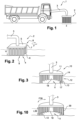
- FIG. 1 schematically illustrates a soil treatment apparatus 1 according to the invention.
- a self-propelled type apparatus on wheels is shown schematically.
- it is a towed apparatus.
- An application head 2 is illustrated mounted on the front of the apparatus 1 at the end of an articulated arm 3.
- several application heads are provided, mounted either at the front of the apparatus or at the rear or in a lateral position.
- the application head is located under the soil treatment apparatus.
- the articulated arm supporting the head is deleted. It is understood that these various variants of the device are adapted to the use of the latter.
- a soil treatment apparatus 1 is used, within the scope of the invention, to treat soils in the broad sense.
- it involves weeding and/or cleaning soils used as a traffic lane for vehicles and/or pedestrians.
- the term soil therefore covers traffic lanes such as roads, streets, highways, sidewalks, driveways, parking lots, docks, runways, railway tracks, terraces, swimming pool coping, and more generally any lanes, private or public, paved or not, on which land vehicles such as cars, trucks, agricultural and public works machinery, cycles, motorcycles, aircraft, trains, pedestrians or animals move. It may therefore be, in the case of a closed structure, the floor of a building for commercial, industrial or other use.
- the apparatus 1 is operated by at least one person, it being understood that the operation of the application head 2 can be carried out by a person dedicated to this task. Indeed, it is appropriate, at all times, to position the application head 2 above a part 4 of the ground to be weeded, this for a variable duration depending on the quantity and/or the nature of the plants present in the area.
- FIG. 2 is a view of the application head 2, without the apparatus 1, only a portion of the articulated arm 3 being illustrated.
- the head 2 is generally configured as a parallelepiped with a square base.
- the base is rectangular or of another geometric shape.
- the head 2 comprises a rigid part 5 defining the bottom of the internal volume of the head 2.
- the side walls of the head 2 are formed by a plurality of elongated members 6. These are illustrated on a larger scale in figures 6 and following.
- the members 6 define, by their length, the height H of the head 2. In other words, the length of the members 6 defines the distance H between the bottom 5 and the part of the ground 4 to be treated.
- the members 6 are independent and fixed, by one end 7, to the periphery 8 of the part 5. This fixing is adapted to ensure at least one degree of freedom for the member 6.
- each member 6 can perform a movement, of an amplitude limited, oscillating, like a pendulum, around its point of fixation. Such a movement, illustrated by the double arrow F, will be detailed later in the text.
- the organs 6 are, here at the figure 2 , illustrated regularly spaced, in a single row and without being in mutual contact. Such a representation facilitates reading.
- the members 6 are, preferably, in mutual contact so as not to leave any empty space between them, to avoid, or at least limit as much as possible, any leakage of microwaves.
- the members 6 can be distributed in a staggered pattern and/or in several rows.
- the end 9, opposite the end 7, is free and is, if not in contact with the ground, at least located at a distance of less than 10 mm from the latter.
- the application head 2 is generally configured as a bell, therefore in a volume open towards the ground.
- the dispersion of the microwaves is limited, upwards, by the presence of the rigid bottom 5 and, laterally, by the members 6.
- FIG 3 is a section of an application head 10 corresponding to another embodiment of the invention.
- the bottom 11 is circular, in the shape of a disc.
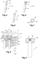
- the elongated members 12 are shown on a larger scale at figure 4 . They correspond to an embodiment of the invention.
- the members 12 comprise a main body 13 and, at one end 14 of the body 13, a rod 15.
- the free end 16 of the rod 15 is of cubic shape.
- the end 16 is of a shape adapted to be secured, with at least one degree of freedom, to the bottom 11 of the application head 10.
- the members 12 are arranged, advantageously in a staggered manner, in several rows on the periphery of the base 11. This produces a wall with a thickness such that any high-frequency electromagnetic radiation is blocked in the internal volume V of the application head 10 defined between the base 11 and the members 12.
- slats 17 are interposed between the members 12. These slats 17 are, for example, made of a material different from the material constituting the members 12. Alternatively, they are made of the same material. As non-limiting examples, the slats 17 are solid or in the form of a lattice, made of textile, metal, or polymers.
- a protective cloth may be fixed at the periphery on the application head 2 or 10.
- the cloth surrounds the members 6 or 12 and the slats 17.
- a cloth is also made of a material suitable for limiting the diffusion of microwaves. In all cases, if it is appropriate to prevent the dispersion of microwaves outside the volume V defined by the application head 2 or 10, it is necessary that, in the volume V, nothing hinders the application of microwaves by the application conduit 18 on the area to be treated 4.
- the body 13 is, for example, made of polymer or textile, covered with metal particles. Alternatively, the metal particles are incorporated into the material constituting the body 13. It is understood that different materials, alone or in combination, can be used to produce the body 13, provided that these materials are impermeable to microwaves and that they make it possible to produce a body 13 that is flexible and insensitive to the environmental conditions encountered outdoors.
- the rod 15 has a much smaller cross-section than the body 13.
- it is in the form of a rod with a circular cross-section.
- it has a square, rectangular or other cross-section.
- the body 13 its cross-section may be square, rectangular, circular or other.
- the rod 15 is, advantageously, made of a material whose capacity to bend and return to its initial shape is at least equal to that of the body 13.
- the end 16 of the rod 15 is configured as a cube, for example made of metal or polymers.
- This cube 16 defines a means of connection between the member 12 and the bottom 11 of the application head. This connection, which provides a degree of freedom to the member 12 relative to the bottom 11, will be described in more detail in Figures 8 and 9 .
- FIG. 5 illustrates another embodiment of an elongated member.
- a member 19 comprises a main body 20 and a rod 21, which are, for simplicity of reading, similar to the body 13 and the rod 15.
- the end 22 of the rod 21 is cross-shaped.
- the cross 22 provides a connection between the member 19 and the bottom of the application head, providing at least one degree of freedom relative to the latter.
- FIG. 6 illustrates in more detail an organ 6, as shown in the figure 2 .
- This comprises a main body 23, for example in the same material as that constituting the members 12 and 19.
- a connecting member 24 between the member 6 and the base 5 of the application head 2 is fixed directly to the body 23.
- the material and/or the dimensions of the body 23 of the member 6 are adapted. In other words, the flexibility of the member 6 as such is greater than that of the members 12 and 19.
- FIG. 7 illustrates in cross-section a body of an elongated organ.
- the body 25 has a circular cross-section.
- the shape is different, for example, it may be the cross-section corresponding to the organs 6, 12 or 19, therefore of square or rectangular shape.
- the body 25 is hollow, advantageously over its entire length.
- the walls 26 of the body 25 are loaded, at least in part, with metal particles, thus making it possible to define a wall impermeable to electromagnetic radiation while preserving the flexibility of the body 25.
- the flexibility of the body 25 is not identical over its entire length but progressive, its free end offering the greatest flexibility. In this way, the behavior of the elongated organ is permanently adapted to the nature and/or geometry of the area to be treated.
- the internal volume V25 of the body 25 is either empty or filled with air maintained at overpressure relative to the external pressure. This produces elongated members whose bodies 25 are in the shape of a sausage, possibly inflatable. The use of air in the bodies of the elongated members generates a saving in weight and material in the production of the elongated members, without altering the impermeability to microwaves. Alternatively, the internal volume V25 of each member is filled with another material, this material being able to be different between the elements.
- FIG 8 illustrates the connection between an elongated member 12 and the base 11 of the application head 10.
- two rails 27, 28 are attached to the periphery of the base 11.
- These rails are configured as a flat-bottomed U-shape, with the ends 29, 30 of the legs 31, 32 bent at right angles and oriented towards each other.
- a space 33 is provided between the ends 29, 30.
- the cross-section of a rail 27 or 28 is configured as a rectangle with a cutout defining the space 33, which is provided in one of the sides of the rectangle.
- Space 33 is facing down looking at the figure 8 , therefore de facto in the direction of the area to be treated 4.
- the members 12 are inserted, by their ends 16, into the open end edge 34, 35 of each rail 27, 28. It is understood that, on the one hand to avoid any accidental exit of the members 12 from the rails 27, 28 and, on the other hand, to be able to introduce the members 12 into the rails 27, 28, the bottom 11 is equipped with a means of access to the rails. This is, by way of non-limiting example, the opening in two parts of the bottom 5 or 11 of the application heads 2 or 10.
- the ends 16 of the members 12 are inserted into the interior volume VR of the rails 27, 28, the rod 15 of each member passing through the space 33, so as to maintain the entire body 13 outside the rail 27, 28.
- the organs 12 can thus pivot in order to adapt to the configuration, therefore to the relief, of the zone to be treated 4, while maintaining contact with the zone 4 via the free ends of the body 13. This limits any leakage of microwaves.
- FIG 9 illustrates another embodiment of the invention.
- a member 6 is introduced into a U-shaped rail referenced 36, therefore of shape and cross-section similar to that which is illustrated in the figure 8 .
- the absence of a rod limits the flexibility of the member and therefore, de facto, the possibilities of movement of the member 6 relative to the rail 36.
- a return member 37 is mounted between the bottom 38 of the rail 36 and the end 24 of the member 6.
- the return member 37 is a coil spring.
- it is a return member of another type, for example a leaf spring, a rubber element or a small cylinder.
- the elongated members are assembled in bundles on rails similar to the rails 27, 28 or 36 but of smaller dimensions.
- the members are inserted into the rails 27, 28 or 36 not one by one but in bundles of several members pre-assembled on so-called internal rails.
- FIG 10 illustrates another embodiment of the invention.
- members 12, therefore similar to those illustrated in figures 2, 3 And 4 are surrounded by a protective cloth 39.
- the cloth 39 completely encircles the volume V and it has a width L39 corresponding to the length of the members 12.
- This cloth 39 is made, in one embodiment, in a material impermeable to microwaves. Alternatively, it is covered on at least one face with a coating impermeable to microwaves. Alternatively, it is composed of several layers or sheets, at least one of which is made of a material impermeable to microwaves.
- the canvas 39 in addition to a role of additional protection against the dispersion of microwaves, can also participate in the destruction of plants present in the area to be treated.
- its free end intended to be in contact with the area to be treated is made of an abrasive metal material, for example metal wires or hooks.
- This action of tearing out the plants can be optimized if the canvas 39 is mounted on a rotating rail, so as to perform a rotational movement according to the double arrow F39 around the bottom 11. It is easily understood that, in one embodiment, the canvas 39 is in two parts, in order to easily replace the part of the canvas in contact with the area to be treated which is the one undergoing the most significant wear.
- the invention is associated with a rotating metal brush, known per se.
- a rotating metal brush known per se.
- Such a brush is positioned either outside the head 2, therefore in front of it in the direction of travel of the vehicle, or in the head 2, for example between the cloth 39 and the elongated members.
Landscapes
- Life Sciences & Earth Sciences (AREA)
- Pest Control & Pesticides (AREA)
- Engineering & Computer Science (AREA)
- Environmental Sciences (AREA)
- Zoology (AREA)
- Insects & Arthropods (AREA)
- Wood Science & Technology (AREA)
- Electromagnetism (AREA)
- Physics & Mathematics (AREA)
- Soil Sciences (AREA)
- Civil Engineering (AREA)
- Structural Engineering (AREA)
- Food Science & Technology (AREA)
- Architecture (AREA)
- Mechanical Engineering (AREA)
- Constitution Of High-Frequency Heating (AREA)
- Catching Or Destruction (AREA)
- Radiation-Therapy Devices (AREA)
Claims (12)
- Applikationskopf (2; 10) einer Vorrichtung (1) zur Bodenbehandlung durch Mikrowellen, die einen starren Teil (5; 11) aus einem für Mikrowellen undurchlässigen Material umfasst, der den Boden (5; 11) eines auf einer Seite offenen Aufnahmevolumens (V) für mindestens eine Leitung zur Führung (18) der Mikrowellen über einen zu behandelnden Bodenbereich (4) bildet, wobei der starre Teil (5; 11) in einem definierten Abstand (H; L39) von dem zu behandelnden Bereich (4) gehalten wird und die Seitenwände des Aufnahmevolumens (V) aus mindestens einem für Mikrowellen undurchlässigen Material hergestellt sind, wobei die freien Enden der Wände des Aufnahmevolumens (V) mit mindestens zwei Organen (6; 12; 19) versehen sind, die dazu geeignet sind, die Streuung der Mikrowellen zu begrenzen, wobei die Organe (6; 12; 19) länglich und unabhängig, haarförmig sind und einen Hauptkörper (13; 20; 23; 25) und an einem Ende (14) des Hauptkörpers einen Schaft (15; 21) umfassen,
wobei ein freies Ende (9) des Körpers (13; 20; 23; 25) jedes Organs (6; 12; 19) dazu geeignet ist, mit dem zu behandelnden Bodenbereich (4) in Kontakt zu stehen, wobei das freie Ende (16; 22) des Schafts (15; 21) des Körpers (13; 20; 23; 25) dazu geeignet ist, mit mindestens einem Freiheitsgrad (F, F1, F2) an der Kante (8; 27, 28, 36) des starren Teils (5; 11) des Applikationskopfes (2; 10) montiert zu sein, mindestens der Körper (13; 20; 23; 25) der Organe (6; 12; 19) aus einem flexiblen Material besteht und die länglichen Organe (6; 12; 19) in mindestens einer Reihe abnehmbar (34, 35) in mindestens einer Schiene (27, 28; 36) montiert sind, die an der Kante (8; 27, 28, 36) des starren Teils (5; 11) des Applikationskopfes (2; 10) angeordnet ist. - Applikationskopf nach Anspruch 1, dadurch gekennzeichnet, dass die länglichen Organe (6; 12; 19) massiv und aus einem Material hergestellt sind, von dem mindestens ein Teil Metallteilchen enthält.
- Applikationskopf nach Anspruch 1, dadurch gekennzeichnet, dass die länglichen Organe (6; 12; 19) hohl sind, mit Wänden, die aus einem Material hergestellt sind, von dem mindestens ein Teil Metallteilchen enthält.
- Applikationskopf nach Anspruch 1, dadurch gekennzeichnet, dass die länglichen hohlen Organe mit einem Ende versehen sind, das dazu geeignet ist, mit einer Quelle von unter Druck stehendem Fluid verbunden zu werden.
- Applikationskopf nach Anspruch 1, dadurch gekennzeichnet, dass die länglichen Organe nach Paketen zusammengesetzt sind, die auf einer Schiene montiert sind, die ihrerseits in die Schiene (27, 28; 36) eingeführt ist, die am Rand (8; 27, 28, 36) des starren Teils (5; 11) des Applikationskopfes (2; 10) angeordnet ist.
- Applikationskopf nach einem der vorhergehenden Ansprüche, dadurch gekennzeichnet, dass die länglichen Organe (6; 12; 19), die am Rand (8; 27, 28, 36) des starren Teils (5; 11) des Applikationskopfes (2; 10) montiert sind, von gleicher Art sind.
- Applikationskopf nach einem der Ansprüche 1 bis 5, dadurch gekennzeichnet, dass die länglichen Organe (6; 12; 17; 19), die am Rand (8; 27, 28, 36) des starren Teils (5; 11) des Applikationskopfes (2; 10) montiert sind, von unterschiedlicher Art sind.
- Applikationskopf nach einem der vorhergehenden Ansprüche, dadurch gekennzeichnet, dass ein Tuch (39) aus einem für Mikrowellen undurchlässigen Material an der Umfangswand des Kopfes (10) montiert ist, welche die länglichen Organe (12) umgibt.
- Applikationskopf nach Anspruch 8, dadurch gekennzeichnet, dass das Tuch (39) mit einem Ende versehen ist, das dazu geeignet ist, ein Ausreißen der auf dem zu behandelnden Bereich vorhandenen Pflanzen zu gewährleisten.
- Applikationskopf nach einem der Ansprüche 8 oder 9, dadurch gekennzeichnet, dass das Tuch (39) aus mindestens zwei Teilen besteht.
- Vorrichtung (1) zur Bodenbehandlung, die mit mindestens einem Applikationskopf (2; 10) nach einem der vorhergehenden Ansprüche ausgestattet ist.
- Vorrichtung zur Bodenbehandlung nach Anspruch 11, dadurch gekennzeichnet, dass sie mindestens eine rotierende Metallbürste umfasst, die mit dem Applikationskopf (2; 10) nach einem der Ansprüche 1 bis 10 verknüpft ist.
Applications Claiming Priority (2)
| Application Number | Priority Date | Filing Date | Title |
|---|---|---|---|
| FR1853280A FR3080001B1 (fr) | 2018-04-14 | 2018-04-14 | Tete d'application d'un appareil de traitement des sols par micro-ondes pourvue d'un organe limitant la dispersion des micro-ondes et appareil correspondant |
| PCT/FR2019/050559 WO2019197741A1 (fr) | 2018-04-14 | 2019-03-14 | Tete d'application d'un appareil de traitement des sols par micro-ondes pourvue d'un organe limitant la dispersion des micro-ondes et appareil correspondant |
Publications (3)
| Publication Number | Publication Date |
|---|---|
| EP3764784A1 EP3764784A1 (de) | 2021-01-20 |
| EP3764784B1 true EP3764784B1 (de) | 2025-01-01 |
| EP3764784C0 EP3764784C0 (de) | 2025-01-01 |
Family
ID=62528702
Family Applications (1)
| Application Number | Title | Priority Date | Filing Date |
|---|---|---|---|
| EP19717529.2A Active EP3764784B1 (de) | 2018-04-14 | 2019-03-14 | Applikatorkopf einer vorrichtung zur behandlung von böden mit mikrowellen mit einem element zur begrenzung der dispersion der mikrowellen und entsprechende vorrichtung |
Country Status (7)
| Country | Link |
|---|---|
| EP (1) | EP3764784B1 (de) |
| JP (1) | JP2021520852A (de) |
| KR (1) | KR20200140900A (de) |
| CA (1) | CA3094914A1 (de) |
| ES (1) | ES3015201T3 (de) |
| FR (1) | FR3080001B1 (de) |
| WO (1) | WO2019197741A1 (de) |
Families Citing this family (1)
| Publication number | Priority date | Publication date | Assignee | Title |
|---|---|---|---|---|
| US12084005B2 (en) | 2021-02-24 | 2024-09-10 | Cnh Industrial Canada, Ltd. | Data acquisition module for an agricultural machine and related systems and assemblies |
Family Cites Families (12)
| Publication number | Priority date | Publication date | Assignee | Title |
|---|---|---|---|---|
| US4031986A (en) | 1974-03-25 | 1977-06-28 | Thompson Tom H | Disk brake construction having stamped support |
| US4319856A (en) * | 1977-01-03 | 1982-03-16 | Microdry Corportion | Microwave method and apparatus for reprocessing pavements |
| US4370534A (en) | 1979-04-09 | 1983-01-25 | Deryck Brandon | Apparatus and method for heating, thawing and/or demoisturizing materials and/or objects |
| AU633679B2 (en) * | 1990-01-24 | 1993-02-04 | Frank Perre | Soil sterilizer |
| KR200189595Y1 (ko) * | 2000-02-29 | 2000-07-15 | 송안인 | 마이크로파 제설기 |
| US6554531B2 (en) | 2001-04-13 | 2003-04-29 | Brian K. Bodish | Apparatus for drying and compacting earthen materials |
| US20030215354A1 (en) * | 2002-05-17 | 2003-11-20 | Advanced Scientific Technologies Corporation | Systems and methods for in situ soil sterilization, insect extermination and weed killing |
| US20120091123A1 (en) * | 2005-01-11 | 2012-04-19 | William Thomas Joines | Microwave system and method for controlling the sterilization and infestation of crop soils |
| ES2350791B1 (es) | 2009-06-15 | 2011-11-16 | Sp Berner Plastic Group, S.L. | Caja plegable |
| US8845234B2 (en) | 2009-06-18 | 2014-09-30 | Microwave Utilities, Inc. | Microwave ground, road, water, and waste treatment systems |
| KR101639941B1 (ko) * | 2015-03-05 | 2016-07-25 | 장흥균 | 마이크로파를 이용한 이동형 잡초 제거장치 |
| CN106614491A (zh) * | 2016-12-19 | 2017-05-10 | 刘晓亮 | 一种保护地歇茬期间微波灭杀地老虎的方法 |
-
2018
- 2018-04-14 FR FR1853280A patent/FR3080001B1/fr active Active
-
2019
- 2019-03-14 EP EP19717529.2A patent/EP3764784B1/de active Active
- 2019-03-14 KR KR1020207032745A patent/KR20200140900A/ko not_active Withdrawn
- 2019-03-14 CA CA3094914A patent/CA3094914A1/fr active Pending
- 2019-03-14 ES ES19717529T patent/ES3015201T3/es active Active
- 2019-03-14 WO PCT/FR2019/050559 patent/WO2019197741A1/fr not_active Ceased
- 2019-03-14 JP JP2021504581A patent/JP2021520852A/ja active Pending
Also Published As
| Publication number | Publication date |
|---|---|
| ES3015201T3 (en) | 2025-04-30 |
| EP3764784C0 (de) | 2025-01-01 |
| FR3080001B1 (fr) | 2021-06-04 |
| CA3094914A1 (fr) | 2019-10-17 |
| WO2019197741A1 (fr) | 2019-10-17 |
| FR3080001A1 (fr) | 2019-10-18 |
| JP2021520852A (ja) | 2021-08-26 |
| KR20200140900A (ko) | 2020-12-16 |
| EP3764784A1 (de) | 2021-01-20 |
Similar Documents
| Publication | Publication Date | Title |
|---|---|---|
| WO2016124804A1 (es) | Máquina de arrastre para la nivelación de suelos y caminos | |
| EP3764784B1 (de) | Applikatorkopf einer vorrichtung zur behandlung von böden mit mikrowellen mit einem element zur begrenzung der dispersion der mikrowellen und entsprechende vorrichtung | |
| FR3082169A1 (fr) | Chassis de vehicule agricole de largeur reglable et vehicule agricole | |
| CA2857583C (fr) | Machine agricole avec un suivi de terrain ameliore pour les organes de travail | |
| EP0103522A1 (de) | Fahrbare Sprühvorrichtung für eine Flüssigkeit zur Behandlung von Pflanzen | |
| FR2957220A1 (fr) | Tracteur enjambeur | |
| FR2717343A1 (fr) | Combinaison d'équipements de travail montés sur un véhicule porteur à roues avant directrices. | |
| EP1479287A1 (de) | Vorrichtung zur Sterilisierung des Bodens | |
| US20070261573A1 (en) | Compactor cleaning system | |
| FR2614910A1 (fr) | Mur d'isolation phonique en particulier pour implantation en bordure de voies de circulation | |
| FR2608944A1 (fr) | Dispositif de projection controlee d'un fluide, tel que par exemple un produit herbicide, sur le sol | |
| EP0060367B1 (de) | Kraftrad zum Reinigen von Bodenflächen | |
| ES2234192T3 (es) | Dispositivo para el arranque mecanico de malas hierbas. | |
| CA2479905C (fr) | Lame chasse-neige flottante avec couteau insere | |
| EP0342065B1 (de) | Maschine zum Nacharbeiten von gepflügtem Land | |
| FR2610961A1 (fr) | Ouvrage leger de consolidation de terrains | |
| FR2617392A1 (fr) | Dispositif deflecteur de poussiere pour appareil de nettoyage | |
| FR2473456A1 (fr) | Element de contact avec le sol pour vehicules a chenilles sans fin | |
| US9534353B1 (en) | Machine for digging or refurbishing swales | |
| US293569A (en) | Isaac s | |
| NL7908843A (nl) | Inrichting voor het graven van greppels, voorzien van een schijf en een afbuigorgaan. | |
| RU2238854C1 (ru) | Ведущее колесо сельскохозяйственных машин и орудий | |
| FR2758046A1 (fr) | Appareil sanitaire pour animaux domestiques | |
| US763650A (en) | Road-grader. | |
| EP1319761A1 (de) | Gerät zum Graben und/oder Reinigen von Gräben und Fahrzeug ausgerüstet mit solch einem Gerät |
Legal Events
| Date | Code | Title | Description |
|---|---|---|---|
| STAA | Information on the status of an ep patent application or granted ep patent |
Free format text: STATUS: UNKNOWN |
|
| STAA | Information on the status of an ep patent application or granted ep patent |
Free format text: STATUS: THE INTERNATIONAL PUBLICATION HAS BEEN MADE |
|
| PUAI | Public reference made under article 153(3) epc to a published international application that has entered the european phase |
Free format text: ORIGINAL CODE: 0009012 |
|
| STAA | Information on the status of an ep patent application or granted ep patent |
Free format text: STATUS: REQUEST FOR EXAMINATION WAS MADE |
|
| 17P | Request for examination filed |
Effective date: 20201012 |
|
| AK | Designated contracting states |
Kind code of ref document: A1 Designated state(s): AL AT BE BG CH CY CZ DE DK EE ES FI FR GB GR HR HU IE IS IT LI LT LU LV MC MK MT NL NO PL PT RO RS SE SI SK SM TR |
|
| AX | Request for extension of the european patent |
Extension state: BA ME |
|
| DAV | Request for validation of the european patent (deleted) | ||
| DAX | Request for extension of the european patent (deleted) | ||
| STAA | Information on the status of an ep patent application or granted ep patent |
Free format text: STATUS: EXAMINATION IS IN PROGRESS |
|
| 17Q | First examination report despatched |
Effective date: 20230111 |
|
| REG | Reference to a national code |
Ref legal event code: R079 Free format text: PREVIOUS MAIN CLASS: A01M0021040000 Ref country code: DE Ref legal event code: R079 Ref document number: 602019064234 Country of ref document: DE Free format text: PREVIOUS MAIN CLASS: A01M0021040000 Ipc: A01M0001220000 |
|
| GRAP | Despatch of communication of intention to grant a patent |
Free format text: ORIGINAL CODE: EPIDOSNIGR1 |
|
| STAA | Information on the status of an ep patent application or granted ep patent |
Free format text: STATUS: GRANT OF PATENT IS INTENDED |
|
| RIC1 | Information provided on ipc code assigned before grant |
Ipc: H05B 6/80 20060101ALI20240906BHEP Ipc: H05B 6/76 20060101ALI20240906BHEP Ipc: A01M 17/00 20060101ALI20240906BHEP Ipc: A01M 21/04 20060101ALI20240906BHEP Ipc: E01H 11/00 20060101ALI20240906BHEP Ipc: A01M 1/22 20060101AFI20240906BHEP |
|
| INTG | Intention to grant announced |
Effective date: 20240920 |
|
| GRAS | Grant fee paid |
Free format text: ORIGINAL CODE: EPIDOSNIGR3 |
|
| GRAA | (expected) grant |
Free format text: ORIGINAL CODE: 0009210 |
|
| STAA | Information on the status of an ep patent application or granted ep patent |
Free format text: STATUS: THE PATENT HAS BEEN GRANTED |
|
| AK | Designated contracting states |
Kind code of ref document: B1 Designated state(s): AL AT BE BG CH CY CZ DE DK EE ES FI FR GB GR HR HU IE IS IT LI LT LU LV MC MK MT NL NO PL PT RO RS SE SI SK SM TR |
|
| REG | Reference to a national code |
Ref country code: GB Ref legal event code: FG4D Free format text: NOT ENGLISH |
|
| REG | Reference to a national code |
Ref country code: DE Ref legal event code: R096 Ref document number: 602019064234 Country of ref document: DE |
|
| REG | Reference to a national code |
Ref country code: CH Ref legal event code: EP |
|
| REG | Reference to a national code |
Ref country code: IE Ref legal event code: FG4D Free format text: LANGUAGE OF EP DOCUMENT: FRENCH |
|
| U01 | Request for unitary effect filed |
Effective date: 20250122 |
|
| U07 | Unitary effect registered |
Designated state(s): AT BE BG DE DK EE FI FR IT LT LU LV MT NL PT RO SE SI Effective date: 20250130 |
|
| REG | Reference to a national code |
Ref country code: ES Ref legal event code: FG2A Ref document number: 3015201 Country of ref document: ES Kind code of ref document: T3 Effective date: 20250430 |
|
| U20 | Renewal fee for the european patent with unitary effect paid |
Year of fee payment: 7 Effective date: 20250325 |
|
| PG25 | Lapsed in a contracting state [announced via postgrant information from national office to epo] |
Ref country code: PL Free format text: LAPSE BECAUSE OF FAILURE TO SUBMIT A TRANSLATION OF THE DESCRIPTION OR TO PAY THE FEE WITHIN THE PRESCRIBED TIME-LIMIT Effective date: 20250101 |
|
| PGFP | Annual fee paid to national office [announced via postgrant information from national office to epo] |
Ref country code: ES Payment date: 20250429 Year of fee payment: 7 |
|
| PG25 | Lapsed in a contracting state [announced via postgrant information from national office to epo] |
Ref country code: NO Free format text: LAPSE BECAUSE OF FAILURE TO SUBMIT A TRANSLATION OF THE DESCRIPTION OR TO PAY THE FEE WITHIN THE PRESCRIBED TIME-LIMIT Effective date: 20250401 Ref country code: IS Free format text: LAPSE BECAUSE OF FAILURE TO SUBMIT A TRANSLATION OF THE DESCRIPTION OR TO PAY THE FEE WITHIN THE PRESCRIBED TIME-LIMIT Effective date: 20250501 |
|
| PG25 | Lapsed in a contracting state [announced via postgrant information from national office to epo] |
Ref country code: HR Free format text: LAPSE BECAUSE OF FAILURE TO SUBMIT A TRANSLATION OF THE DESCRIPTION OR TO PAY THE FEE WITHIN THE PRESCRIBED TIME-LIMIT Effective date: 20250101 |
|
| PG25 | Lapsed in a contracting state [announced via postgrant information from national office to epo] |
Ref country code: GR Free format text: LAPSE BECAUSE OF FAILURE TO SUBMIT A TRANSLATION OF THE DESCRIPTION OR TO PAY THE FEE WITHIN THE PRESCRIBED TIME-LIMIT Effective date: 20250402 |
|
| PG25 | Lapsed in a contracting state [announced via postgrant information from national office to epo] |
Ref country code: CZ Free format text: LAPSE BECAUSE OF FAILURE TO SUBMIT A TRANSLATION OF THE DESCRIPTION OR TO PAY THE FEE WITHIN THE PRESCRIBED TIME-LIMIT Effective date: 20250101 |
|
| PG25 | Lapsed in a contracting state [announced via postgrant information from national office to epo] |
Ref country code: SM Free format text: LAPSE BECAUSE OF FAILURE TO SUBMIT A TRANSLATION OF THE DESCRIPTION OR TO PAY THE FEE WITHIN THE PRESCRIBED TIME-LIMIT Effective date: 20250101 |
|
| PG25 | Lapsed in a contracting state [announced via postgrant information from national office to epo] |
Ref country code: MC Free format text: LAPSE BECAUSE OF FAILURE TO SUBMIT A TRANSLATION OF THE DESCRIPTION OR TO PAY THE FEE WITHIN THE PRESCRIBED TIME-LIMIT Effective date: 20250101 |
|
| REG | Reference to a national code |
Ref country code: CH Ref legal event code: H13 Free format text: ST27 STATUS EVENT CODE: U-0-0-H10-H13 (AS PROVIDED BY THE NATIONAL OFFICE) Effective date: 20251024 |
|
| PG25 | Lapsed in a contracting state [announced via postgrant information from national office to epo] |
Ref country code: SK Free format text: LAPSE BECAUSE OF FAILURE TO SUBMIT A TRANSLATION OF THE DESCRIPTION OR TO PAY THE FEE WITHIN THE PRESCRIBED TIME-LIMIT Effective date: 20250101 |
|
| PLBE | No opposition filed within time limit |
Free format text: ORIGINAL CODE: 0009261 |
|
| STAA | Information on the status of an ep patent application or granted ep patent |
Free format text: STATUS: NO OPPOSITION FILED WITHIN TIME LIMIT |
|
| 26N | No opposition filed |
Effective date: 20251002 |
|
| GBPC | Gb: european patent ceased through non-payment of renewal fee |
Effective date: 20250401 |
|
| PG25 | Lapsed in a contracting state [announced via postgrant information from national office to epo] |
Ref country code: GB Free format text: LAPSE BECAUSE OF NON-PAYMENT OF DUE FEES Effective date: 20250401 |
|
| PG25 | Lapsed in a contracting state [announced via postgrant information from national office to epo] |
Ref country code: CH Free format text: LAPSE BECAUSE OF NON-PAYMENT OF DUE FEES Effective date: 20250331 |
|
| PG25 | Lapsed in a contracting state [announced via postgrant information from national office to epo] |
Ref country code: IE Free format text: LAPSE BECAUSE OF NON-PAYMENT OF DUE FEES Effective date: 20250314 |