EP0342065B1 - Maschine zum Nacharbeiten von gepflügtem Land - Google Patents
Maschine zum Nacharbeiten von gepflügtem Land Download PDFInfo
- Publication number
- EP0342065B1 EP0342065B1 EP19890400184 EP89400184A EP0342065B1 EP 0342065 B1 EP0342065 B1 EP 0342065B1 EP 19890400184 EP19890400184 EP 19890400184 EP 89400184 A EP89400184 A EP 89400184A EP 0342065 B1 EP0342065 B1 EP 0342065B1
- Authority
- EP
- European Patent Office
- Prior art keywords
- tractor
- soil
- post
- fact
- blade
- Prior art date
- Legal status (The legal status is an assumption and is not a legal conclusion. Google has not performed a legal analysis and makes no representation as to the accuracy of the status listed.)
- Expired - Lifetime
Links
Images


Classifications
-
- A—HUMAN NECESSITIES
- A01—AGRICULTURE; FORESTRY; ANIMAL HUSBANDRY; HUNTING; TRAPPING; FISHING
- A01B—SOIL WORKING IN AGRICULTURE OR FORESTRY; PARTS, DETAILS, OR ACCESSORIES OF AGRICULTURAL MACHINES OR IMPLEMENTS, IN GENERAL
- A01B31/00—Drags
-
- A—HUMAN NECESSITIES
- A01—AGRICULTURE; FORESTRY; ANIMAL HUSBANDRY; HUNTING; TRAPPING; FISHING
- A01B—SOIL WORKING IN AGRICULTURE OR FORESTRY; PARTS, DETAILS, OR ACCESSORIES OF AGRICULTURAL MACHINES OR IMPLEMENTS, IN GENERAL
- A01B29/00—Rollers
-
- A—HUMAN NECESSITIES
- A01—AGRICULTURE; FORESTRY; ANIMAL HUSBANDRY; HUNTING; TRAPPING; FISHING
- A01B—SOIL WORKING IN AGRICULTURE OR FORESTRY; PARTS, DETAILS, OR ACCESSORIES OF AGRICULTURAL MACHINES OR IMPLEMENTS, IN GENERAL
- A01B59/00—Devices specially adapted for connection between animals or tractors and agricultural machines or implements
- A01B59/04—Devices specially adapted for connection between animals or tractors and agricultural machines or implements for machines pulled or pushed by a tractor
- A01B59/044—Devices specially adapted for connection between animals or tractors and agricultural machines or implements for machines pulled or pushed by a tractor having pulling means arranged on the middle part of the tractor
-
- A—HUMAN NECESSITIES
- A01—AGRICULTURE; FORESTRY; ANIMAL HUSBANDRY; HUNTING; TRAPPING; FISHING
- A01B—SOIL WORKING IN AGRICULTURE OR FORESTRY; PARTS, DETAILS, OR ACCESSORIES OF AGRICULTURAL MACHINES OR IMPLEMENTS, IN GENERAL
- A01B63/00—Lifting or adjusting devices or arrangements for agricultural machines or implements
- A01B63/14—Lifting or adjusting devices or arrangements for agricultural machines or implements for implements drawn by animals or tractors
- A01B63/145—Lifting or adjusting devices or arrangements for agricultural machines or implements for implements drawn by animals or tractors for controlling weight transfer between implements and tractor wheels
Definitions
- the invention relates to a plowing resumption machine which will find its application in particular in the agricultural field.
- the cultivator Before this winter rest period, the cultivator must prepare the soil, generally he plows the field. The earth is turned over and is dug by furrows.
- the technique of working the soil in autumn is different, because on the one hand, the plowing sometimes generates the formation of large clods of soil which come to be placed above the level of the ground, and on the other hand, the work of the ground is done immediately after plowing to avoid the harmful effect of the rain.
- the land is plowed and then immediately after passing traditional systems such as rotary harrows or the like, capable of forming the seedbed, this operation being immediately followed by the sowing phase.
- traditional systems such as rotary harrows or the like
- document FR-A-739.336 discloses an automatic leveling shovel for land, which finds one of its applications in the field of agriculture, and which is suitable for being coupled to a tractor for working the soil before sowing. .
- the apparatus comprises soil working tools having a set of coulters making it possible to loosen the crust of the earth, followed by a transverse leveling tool making it possible to level the ground by accumulating the earth crumbled by the coulters if one is in a situation of bumps or by filling the depressions and hollows of the ground with the earth crumbled by the coulters before in the opposite situation.
- the apparatus includes means for supporting the tools which determine the average level of the ground in the working area of said tools, means for adjusting the height of the tools relative to the ground, and means flexible link connecting said support means to the tractor chassis.
- the soil is first crumbled by means of harrow teeth or coulters then it is sought to distribute the earth using a conventional leveling element which only intervenes after resumption of plowing by the teeth a harrow or coulters.
- Document FR-A-1,339,947 also discloses a ground leveler intended to be coupled to a tractor which, after the passage of the wheels of a tractor equipped with an agricultural implement, makes it possible to bridge the grooves formed by the passage of the wheels of this tractor.
- This device is essentially formed by a sled, each disposed behind a wheel of the tractor which, sliding on the ground, blocks the grooves created by the wheels of the tractor.
- This document describes a tool for "repairing" the state of the ground but in no case does it allow a resumption of plowing in order to prepare the soil for sowing.
- document EP-A-199,656 also discloses a tractor load transfer device placed between the wheels of the latter under the frame in order to apply pressure to the ground by means of rollers.
- the apparatus described in document US-A-3,261,118 comprises two tractors behind which is coupled a frame supporting a scraper of a very large width.
- the frame At the front, the frame is maintained and secured to the tractors by a rigid and pivoting link.
- the frame At the rear, the frame is supported by two axles with separate lifting control by means of jacks.
- the combination of these different elements is provided to allow the diagonal setting of the squeegee both from right to left, or vice versa, by advancing one tractor relative to the other, and from top to bottom, or vice versa by raising or lowering the independent rear axles, which affects the tilt of the built.
- the main purpose of the present invention is to present a plowing resumption machine which is specialized in its function and which replaces the vibrocultivators and animated harrows traditionally used.
- One of the aims of the present invention is to replace all of these various cultural methods with a new way of working in order to achieve sufficient leveling in a single pass with a minimum of tensile force.
- the applications of the machine of the present invention make it possible to sufficiently limit the effects of destruction of the internal structure of the soil due to the passage of tractors, to make unnecessary the work of loosening intended to try to correct this compaction.
- the power absorbed by the machine of the invention is very modest.
- the benefits of this characteristic are very important.
- the use of a lower power tractor can perfectly well be envisaged. It follows that it is a lighter tractor and using narrow twin wheels, it is possible to locate the compaction of the soil on a small surface and in interline crops.
- the tillage can be done over a large width of the order of 10 m even with a low power tractor.
- the field can be worked at low speed, the width of the plowing resumption machine makes it possible to make up for the low speed by reducing the number of passes necessary to cover the surface.
- Another object of the present invention is to present a plowing resumption machine which is economical in particular in terms of its manufacture. Indeed, it is a specialized machine whose construction calls for traditional techniques. Its longevity is ensured by the fact that there are no moving parts. The absence of motorization is also appreciable on the economic level.
- Another object of the present invention is to propose a variant of a plowing resumption machine making it possible to widen its range of use and to improve the leveling work and to authorize a loosening of the soil of the leveled surface for work on land that has not been frozen.
- One of the aims of the present invention is to propose a plowing resumption machine making it possible on the one hand to cut the plowed earth, then on the other hand to obtain a crumbling of the earth thus cut sufficient for the constitution of a bed seed capable of supporting sowing immediately after this work.
- An object of the present invention is to provide a plowing resumption machine which allows such preparation of the ground over a large width at each pass without requiring superabundant tractor power despite the completion of all the steps in a single pass.
- Another object of the present is to present a plowing resumption machine, which also makes it possible to simultaneously carry out a modular load transfer of part of the mass of the tractor to the rear part of said plowing resumption machine.
- Another object of the present invention is to provide a plowing resumption machine fitted to a wheeled tractor which will reduce the ground pressure of the tractor tires.
- the plowing resumption machine is characterized in that it comprises at least one second transverse, leveling, concave and curved blade, non-stick, which cuts the ground surface, crumbles the earth, and is flush with the surface of the ground, provided at the rear of the first blade, the lower edges of said first and second blades being offset with respect to each other to work the soil successively.
- the agrarian plowing resumption assembly comprising a tractor and a plowing resumption machine, as mentioned above, is characterized in that it has means for artificially unloading all of the tractor wheels capable of creating at least one load transfer of the tractor wheels to the rear part of said support means.
- the present invention relates to a plowing resumption machine which will find its application in particular in the agricultural field.
- the known technical developments have been directed towards the development of powerful tools which work the soil in depth and which unfortunately do not allow to benefit from certain natural actions.
- the present invention in particular seeks to take advantage of the action of the gel on the ground.
- the plowing resumption machine is intended to exert its action directly on plowed ground and its role is to cause only a leveling of the soil on the surface, this in order not to destroy the qualities acquired by the action of frost.
- the soil is naturally prepared during the winter and only leveling is ensured before planting the seedlings.
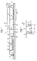
- FIG. 1 illustrates the plowing resumption machine 1 of the present invention which is intended to be coupled to a tractor 2.
- a machine exerting a very low pressure on the ground .
- a machine mounted on tracks, as illustrated in Figure 1 is particularly well suited.
- the pressure under the tracks can be reduced to around 350 g / cm2, that is to say a value of the order of half that obtained by using wheels.
- the machine action of this invention is limited to the surface of the ground by a leveling action, the power absorbed is low, which makes it possible to envisage working over a substantial width of the order of 10 m for a power of 80 horses.
- the plowing machine 1 of the present invention comprises a transverse blade 3 which is flush with the soil surface.
- This curved, non-stick blade allows you to cut the heads of large clods of earth and use it to fill the roughness of the ground to even it out. All the difficulty is to adjust the height of the leveling blade 3 so that it performs a leveling of the ground surface without unnecessarily shaking the earth. This height adjustment must be permanent to take account of the slope of the ground, it must not however be disturbed by local roughness or bumps.
- the plowing resumption machine 1 of the present invention consists of means 4 for supporting the said equalizing blade 3 which determines the average level of the soil in the working area of the blade 3.
- FIG. 2 illustrates the operation of the plowing resumption machine 1 of the present invention.
- the height of attachment of the leveling blade 3 to the support means 4 is adjustable. It is desirable that the action of this blade 3 is limited to the surface of the ground, however, in certain circumstances in particular when there are important holes to be filled, it is sometimes necessary to adjust the blade so that it s '' moderately forces into the soil
- the action of the blade 3 should be limited to cutting the heads of large clods of earth and pushing the cut parts to the surface of the ground to fill the holes. For this action to take place in good conditions, it is desirable that the blade has a concave shape and that the lower edge 5 of the blade 3 has a sharp edge.
- the blade will be made of a material with non-stick properties to avoid sticking of the earth on its surface. Stainless steel is perfectly suited for this purpose.
- the support means 4 of the blade 3 have freedom of vertical movement relative to the tractor which allows them to freely follow the ground surface.
- the support means 4 are in the form of an armature 6 which rests on the ground 7 by its front 8 and rear 9 and at the center of which the equalizing blade 3 is fixed.
- the fact that the armature 6 rests on the ground at two front and rear points means that the reinforcement when sufficiently dimensioned determines an average level of the ground. Generally, a length greater than 2 m is required with regard to the reinforcement to determine a correct average level of the ground.
- the frame 6 rests on the ground 7 in its front part 8 by means of pads 10.
- the pads can for example be distributed over the front part of the frame 6 and spaced about 30 cm apart.
- the frame In its rear part 9, the frame rests on the ground in particular by means of wheels, or skids or rotary harrows 11.
- the rotary harrow is a kind of small squirrel cage which is not driven by the PTO but which, because of its small diameter, has a high speed of rotation allowing a crumbling effect.
- the frame 6 is connected to the chassis 12 of the tractor by means of flexible connection means 13 such as chains.
- flexible connection means 13 such as chains.
- the plowing resumption machine of the present invention makes it possible to work over a very large width, which reduces the proportion of packed areas and to have only minimum settlement at level of the tracks.
- the blade 3 is formed in three sections, however it could also be envisaged to produce independent blade sections or articulated to each other by element 1 to 4 meters wide to perfectly follow the terrain.
- plowing resumption machine harnessed to the front linkage of tractors carrying out sowing or planting is commonly used.
- the front pads of the machine could perfectly be replaced by squirrel cage or other devices, which, in certain cases, makes it possible to envisage a transfer of part of the weight of the tractor to the machine.
- Figures 3 and 4 relate to improvements made to the plowing resumption machine as shown in Figures 1 and 2, to ensure the preparation of the soil for sowing on land wintered or not, having suffered frost or not.
- the realization of the present invention equipped with these improvements will allow on the one hand to work, with regard to France, for example in the spring, a soil having undergone the winter rest and the beneficial action of the gel in order to prepare the field for spring sowing.
- the machine of the invention will make it possible to work the soil after an autumn plowing, not wintered, in order to authorize the preparation and the realization of a traditional seed bed, this by working fundamentally different from traditional methods known to date.
- Figure 3 shows the base of plowing machine 1 such as previously described.
- the machine 1 comprises at least a first transverse blade 3 which is flush with the surface of the ground.
- This blade is curved, of concave shape, non-stick to cut the heads of the clods of earth and allow the leveling of the roughness of the ground, and adjustable in height, by means not shown in the figures, within the reach of man. art.
- the machine 1 for resuming plowing comprises means 4 for supporting the said first equalizing blade 3, which determine the average level of the soil in the working area of the blade 3, and which are, for example, in the form a frame 6 which rests on the ground 7 by its front 8 and rear 9, said first equalizing blade 3 being fixed between the pads 10 and the wheels, pads or rotary harrows 11 or the like.
- the frame 6 is connected to the chassis of the tractor, shown diagrammatically at 12 in the figure, by means of flexible connection means 13, such as chains, allowing free vertical clearance of the frame while ensuring its horizontal movement.
- the machine of the present invention can either be pushed or pulled by the tractor, the direction of advance of the machine being identified by arrow 14 in the figure.
- Such arrangements allow said first equalizing blade 3, through its lower edge 5 and its cutting edge, to cut the heads of large clods of earth 15 without entering too deeply into the soil itself.
- the machine 1 of the present invention advantageously comprises a second blade 16, transverse, leveling, curved and non-stick, provided for the back of said first blade 3.
- the first blade allows work on large clods of soil, without seeking to carry out fine work at leveling, and the second blade performs successive work and cuts a second time the surface of the soil previously prepared by the blade 3.
- the first blade 3 performs a pre-leveling by cutting the large clods 15 and roughly leveling the ground then the second blade 16 achieves a fine leveling by cutting thus formed and distributing the crumbled earth in the hollow of the ground.
- the second blade 16 is similar in shape to the first blade 3, that is to say it has a concave shape and a lower edge 17 equipped with a cutting edge.
- These blades will be made of a material having anti-adhesion properties in order to avoid sticking of the earth to its surface, for example stainless steel.
- the second blade 16 will also be equipped with means for adjusting the height with respect to the frame 6 and supported by said support means 4 between the support points 8 and 9.
- said lower edge 17 of the second blade 16 will be arranged lower, relative to the ground than that 5 of said first blade 3.
- Figure 4 shows precisely this detail and there is shown pa “ ⁇ h” the height difference between the cutting edge 5 of the first blade 3 and the cutting edge 17 of the second blade 16.
- the spacing "e” between said first and second blades 3, 16 is adjustable, depending on the terrain configurations from 30 cm up to 1.50 m.
- the set of blades 3, 16 being placed in the part median between the supports 8 and 10 of the frame 6. Good results have been noted by providing a spacing "e", of the order of 50 to 100 cm.
- the machine 1 of the present invention advantageously includes harrows 18 provided at the rear of the leveling blades which will complete the action of the latter and prepare a seedbed.
- Said harrows 18 are coupled and connected to the armature frame 6 of the machine by one or more connections as shown in FIG. 1 in order to ensure a floating mounting of the harrows and to control their depth of penetration into the ground without it is excessive.
- the harrows are in particular coupled by a chain 19 behind the second blade 16 and connected to the frame 6 via a second chain 20. Such an arrangement will also ensure their lifting when they are not used.
- the plowing resumption machine as described above is entirely placed at the front of the propulsion unit. Thus, it can be carried out behind the sowing directly after such tillage.
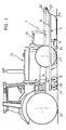
- a tracked vehicle as shown in Figure 1, can be used but is not widely used on farms. By cons, the use of wheeled tractor is more common and it is under these conditions that the improvement object of Figures 5 and 6 was developed.
- a wheeled tractor 22 as illustrated in FIG. 5. It is a conventional type tractor whose power can for example be located in the vicinity from 80 to 150 horsepower.
- the tractor 22 preferably uses paired front 23 and rear 24 wheels.
- the spacing between the twin wheels 23 and 24 will preferably be determined so that it corresponds to the spacing between the cultivation lines, for example 0.45 m.
- the front and rear wheels of the tractor 22 will also preferably be aligned so as to create only a single trace which will be condemned for sowing due to the compaction caused.
- the plowing resumption machine 1 is substantially identical to that described above. It comprises a frame 6 for supporting a transverse leveling blade 3, front shoes 27 determine the ground clearance of the frame, and a rotary harrow 28 with single or double cages 29 and 30 is placed at the rear of the frame 6 for on the one hand determining an average level of the soil in combination with the pads 27 and on the other hand ensuring a crumbling and a compaction of the earth favorable for the seed drill.
- the plowing resumption machine 1 of the present invention has means for artificially unloading all of the wheels 23 and 24 of the tractor 22. This property is obtained without detrimental action on the quality of the work of the machine 1 On the contrary, the advantages of this load shedding are manifold. Firstly, the point of application of this load shedding being in the center of the tractor, all the wheels of the latter are affected.
- this shedding relates to the entire width of the worked land which can go up to 8 m or more, so it can be important if necessary.
- this load transfer being adjustable from the driving position, it is possible to adapt it to the variable conditions encountered in the field.
- the load-shedding means of the present invention make it possible to carry the load of the wheels 23 and 24 of the tractor on the rotary harrow 28.
- the load-shedding means are in the form of a flexible connection 31 placed between the front of the frame 6 and the upper chassis 32 of the tractor 22, as well as an elastic connection, shown diagrammatically in FIG. 1 by a arrow 33, which connects the frame of the tractor 22 and the rear of the frame 6 of the machine 1.
- This elastic connection can in particular be achieved by double-acting cylinders, supplied under variable pressure from the hydraulic circuit of the tractor, bearing on the one hand on the frame of the tractor and on the other hand on a spreader of load distribution on rotary harrows, using traditional techniques.
- the flexible link 31 drives the armature 6 without any vertical stress being applied to it.
- a particular arrangement of the tools for the plowing resumption machine 1 is adopted to allow load transfer.
- the frame 6 is partially arranged under the chassis of the tractor 22 so that the rotary harrow 28 is placed between the front wheels 23 and the rear 24 of the tractor 22.
- the elastic connection 33 which is applied to the armature 6 vertically of the rotary harrow 28 is for example in the form of a cylinder with large clearance. It is indeed essential that the frame 6 can follow the roughness of the ground freely.
- the tractor 22 does must not cause the rotary harrow 28 to be reinforced in the ground.
- jacks are placed on either side of the tractor 22 so that the load applied to the frame 6 is balanced.
- the load transfer is at most from one ton to 1.5 tonnes. on either side of the tractor. In total, it is thus possible to reduce the ground pressure exerted by the tractor wheels 22 by 30%.
- the elastic connection 33 can also be in the form of a suspension with a hydropneumatic accumulator with a bladder, as is found on agricultural equipment.
- the pressure applied by the tractor 22 to the frame 6 is substantially constant and independent of the aspects of the terrain.
- the leveling blade 3 and the parts 27 are placed at the front of the tractor 22.
- this arrangement leaves the rear of the tractor 22 entirely free for, for example, placing a traditional or precision seed drill. In this way, all of the operations can be carried out in a single pass. It is interesting to level, loosen, and "compress" the soil in a single operation because this avoids the risk of rain which could occur in the event of successive independent operations.
- the width of the plowing resumption machine 1 can be up to ten meters. It is therefore desirable to split its manufacturing transversely to reduce the risk of overhangs and more easily follow hilly terrain.
- the frame in the example chosen from Figure 6, is divided into three parts hinged together. This also makes it possible to fold the sides to facilitate traffic on the roads and on the roads.
- the lifting of the plowing resumption machine 1 has been envisaged.
- a standard standard mounting of the front linkage 34 of the tractor is used, equipped with lower arms provided with hydraulic jacks which causes the rotation of the chassis 32 and the lifting of the frame 6 via the chain 11.
- the rear part of the armature is maneuvered using jacks 33 which cause the armature 5 to rise.
- the rotary harrow 28 is positioned substantially under the center of gravity of the tractor 22.
Landscapes
- Life Sciences & Earth Sciences (AREA)
- Engineering & Computer Science (AREA)
- Mechanical Engineering (AREA)
- Soil Sciences (AREA)
- Environmental Sciences (AREA)
- Zoology (AREA)
- Soil Working Implements (AREA)
- Agricultural Machines (AREA)
Claims (17)
- Ackerfräse, die ihre Anwendung auf dem Gebiet der Landwirtschaft finden wird und geeignet ist, an einen Schlepper gekuppelt zu werden, um die Aufbereitung der Böden für das Besäen, vor der Winterzeit oder nicht, dadurch zu sichern, daß die Bodenhöhe oberflächig feinplaniert wird, ohne tief einzudringen oder eine Senkung zu bewirken, wobei die genannte Maschine (1) umfaßt:- Bodenbearbeitungswerkzeuge (3; 3, 16; 3, 35; 3, 16, 18), die wenigstens ein querverlaufendes, schneidendes Planierwerkzeug (3) umfaßt,- Werkzeugabstützmittel (4), die die durchschnittliche Bodenhöhe (7) im Arbeitsbereich der genannten Werkzeuge bestimmen und als ein Rahmen ausgestaltet sind, der nur über dessen Vorderteil (8; 27) und dessen Hinterteil (9; 28) auf dem Boden (7) ruht,- Höheneinstellmittel für die Werkzeuge bezüglich des Bodens,- biegsame Verbindungsmittel (13), die die genannten Abstützmittel (4) der genannten Werkzeuge mit dem Unterbau des Schleppers verbinden, um eine senkrechte Bewegungsfreiheit bezüglich des Schleppers zu erlauben, die es gestattet, die Unebenheiten des Bodens (7) zu folgen,
dadurch gekennzeichnet, daß:- das erste Bodenbearbeitungswerkzeug ständig als ein hohlgewölbtes und inwärts gekrümmtes, nichtanhaftendes, querverlaufendes Planiermesser (3) ausgestaltet ist, dessen Befestigungshöhe auf den vorgesehenen Abstützmitteln (4) einstellbar ist, um bei der Vorwärtsbewegung der Maschine die Bodenoberfläche zu zerschneiden, den Boden zu zerbröckeln und die Bodenoberfläche (7) auszugleichen. - Ackerfräse nach Anspruch 1, dadurch gekennzeichnet, daß sie wenigstens ein zweites, hinter dem ersten Messer vorgesehenes, hohlgewölbtes und inwärts gekrümmtes, nichtanhaftendes Planier-Quermesser (16) umfaßt, das die Bodenoberfläche zerschneidet, den Boden zerbröckelt und die Bodenoberfläche ausgleicht, wobei die Unterkanten (5, 17) der genannten ersten und zweiten Messer (3, 16) zu einander versetzt sind, um den Boden aufeinanderfolgend zu bearbeiten.
- Ackerfräse nach Anspruch 1, dadurch gekennzeichnet, daß die genannte Unterkante (17) des zweiten Messers (16) auf dem Boden bezogen niedriger ist als diejenige (5) des genannten ersten Messers (3).
- Ackerfräse nach Anspruch 1 oder 2, die dazu bestimmt ist, von einem Schlepper geschleppt oder getrieben zu werden, dadurch gekennzeichnet, daß das oder die genannten Messer (3, 16) in der Mitte des genannten Rahmens (6) befestigt sind.
- Ackerfräse nach Anspruch 4, dadurch gekennzeichnet, daß der Rahmen (6) an dessen Vorderteil (8) über Gleitschienen (10) auf dem Boden ruht und/oder an dessen Hinterteil (9) über Dreheggen (11) auf dem Boden ruht und/oder über Ketten (13) mit dem Unterbau (12) des Schleppers verbunden ist.
- Ackerfräse nach Anspruch 4, dadurch gekennzeichnet, daß die Länge des Rahmens (6) 2 m überschreitet.
- Ackerfräse nach Anspruch 1 oder 2, dadurch gekennzeichnet, daß das oder die genannte Messer (3, 16) einen schneidenden Unterrand (5, 17) aufweisen.
- Ackerfräse nach Anspruch 3, dadurch gekennzeichnet, daß der Abstand zwischen den genannten Kanten (5, 17) von 0 bis 10 cm und/oder der Abstand zwischen den genannten ersten (3) und zweiten (16) Messern von 30 cm bis 1,50 m einstellbar ist.
- Ackerfräse nach Anspruch 1, dadurch gekennzeichnet, daß an das genannte erste Messer (4) eine Reihe von zusätzlichen Messern anschliessen.
- Ackerfräse nach Anspruch 2, dadurch gekennzeichnet, daß die Höhe des Zweiten Messers (16) gleich derjenigen oder geringer als diejenige des ersten Messers (3) und der Krümmungsradius der genannten Messer (3, 16) derartig ist, daß der Boden mit einen selben Winkel angeschnitten wird.
- Ackerfräse nach Anspruch 1 oder 2, dadurch gekennzeichnet, daß sie an der Hinterseite der Planiermesser (3, 16) vorgesehene Eggen (18) der Art mit starren und/oder vibrierenden Zähnen umfaßt, deren Wirkungstiefe kontrolliert ist.
- Ackerfräseinheit, umfsassend einen Schlepper (22) und eine Ackerfräse (1) nach Anspruch 1, dadurch gekennzeichnet, daß sie Mittel (33) umfaßt, um die sämtlichen Räder (23 und 24) des Schleppers (22) künstlich vom toten Gewicht zu befreien, die geeignet sind, wenigstens eine Lastübertragung von den Rädern (23 und 24) des Schleppers (22) auf den Hinterteil (9; 28) der genannten Abstützmittel (4, 6) zu bewirken.
- Ackerfräseinheit nach Anspruch 12, dadurch gekennzeichnet, daß die Mittel zum Befreien vom toten Gewicht als eine biegsame Verbindung (31) zwischen dem Unterbau des Schleppers (22) und dem Vorterteil des Abstützrahmens (6) und eine elastische Verbindung (33) zwischen der Mitte des Unterbaus des Schleppers (22) und dem Hinterteil des Abstützrahmens (6) ausgestaltet sind.
- Ackerfräseinheit nach Anspruch 12, dadurch gekennzeichnet, daß der Abstützrahmen (6) zum Teil so unterhalb des Unterbaus des Schleppers (22) angeordnet ist, daß der Hinterteil (9; 28) der genannten Abstützmittel (4, 6) zwischen den Vorder- (23) und den Hinterrädern (24) des Schleppers (22) angeordnet sind.
- Ackerfräseinheit nach Anspruch 12, dadurch gekennzeichnet, daß die Gleitschienen (10; 27) und das oder die querverlaufenden Planiermesser (3) vor dem Schlepper (22) angeordnet sind.
- Ackerfräseinheit nach Anspruch 13, dadurch gekennzeichnet, daß die elastische Verbindung (33) als ein großhubiger Hebebock oder eine Federung mit Druckwasserblasenspeicher mit Luftbelastung ausgestaltet ist.
- Ackerfräseinheit nach Anspruch 13, dadurch gekennzeichnet, daß der Schwerpunkt des Schleppers (22) sich im wesentlichen lotrecht zur Drehegge (28; 30) befindet.
Applications Claiming Priority (4)
| Application Number | Priority Date | Filing Date | Title |
|---|---|---|---|
| FR8806741A FR2631204B2 (fr) | 1987-07-24 | 1988-05-11 | Machine de reprise de labour |
| FR8806741 | 1988-05-11 | ||
| FR8900978A FR2641665B2 (fr) | 1987-07-24 | 1989-01-19 | Perfectionnements a la machine de reprise de labour |
| FR8900978 | 1989-01-19 |
Publications (2)
| Publication Number | Publication Date |
|---|---|
| EP0342065A1 EP0342065A1 (de) | 1989-11-15 |
| EP0342065B1 true EP0342065B1 (de) | 1995-04-12 |
Family
ID=26226676
Family Applications (1)
| Application Number | Title | Priority Date | Filing Date |
|---|---|---|---|
| EP19890400184 Expired - Lifetime EP0342065B1 (de) | 1988-05-11 | 1989-01-23 | Maschine zum Nacharbeiten von gepflügtem Land |
Country Status (2)
| Country | Link |
|---|---|
| EP (1) | EP0342065B1 (de) |
| DE (1) | DE68922133T2 (de) |
Families Citing this family (5)
| Publication number | Priority date | Publication date | Assignee | Title |
|---|---|---|---|---|
| FR2692100B1 (fr) * | 1992-06-15 | 1994-09-23 | Michel Hamot | Machine de préparation des sols, destinée à équipe, un engin moteur, comportant des moyens de rappuyage. |
| FR2729815A1 (fr) * | 1995-01-30 | 1996-08-02 | Belleghem Herve Aime Joseph Va | Lame niveleuse agricole |
| CN106612660A (zh) * | 2016-10-18 | 2017-05-10 | 广西高农机械有限公司 | 一种喷洒水高效翻土农机装置 |
| DE102017007607A1 (de) * | 2017-08-14 | 2019-02-14 | Rwe Power Ag | Lockergesteinshobel |
| CN108377685B (zh) * | 2018-05-25 | 2024-01-12 | 黑龙江京卓农业科技有限公司 | 蔬菜种植用设备 |
Family Cites Families (10)
| Publication number | Priority date | Publication date | Assignee | Title |
|---|---|---|---|---|
| FR739336A (de) * | 1933-01-06 | |||
| US1364007A (en) * | 1920-03-25 | 1920-12-28 | Thomas H Thompson | Combined harrower and leveler |
| DE698144C (de) * | 1938-04-21 | 1940-11-02 | Dr Curt Muetterlein | Vielfachgeraet zur Bodenbearbeitung |
| GB738388A (en) * | 1952-08-01 | 1955-10-12 | J T Wade & Son Ltd | Improvements relating to agricultural implements |
| US2886906A (en) * | 1956-07-26 | 1959-05-19 | Elmer A Moses | Ground leveling implement |
| FR1339947A (fr) * | 1962-11-27 | 1963-10-11 | Niveleur de terrain | |
| US3261118A (en) * | 1964-04-10 | 1966-07-19 | Levi J Litherland | Land leveler |
| GB2158019A (en) * | 1984-05-04 | 1985-11-06 | Charles David Bealby | Soil compression apparatus |
| FR2580893B1 (fr) * | 1985-04-24 | 1988-08-26 | Pollet Albert | Appareil perfectionne pour la preparation des sols au moyen d'un rouleau sous le tracteur et dont la pression exercee au sol est reglable, avant ou pendant le travail. |
| FR2618287B1 (fr) * | 1987-07-24 | 1990-07-06 | Hamot Michel | Machine de reprise de labour |
-
1989
- 1989-01-23 DE DE1989622133 patent/DE68922133T2/de not_active Expired - Fee Related
- 1989-01-23 EP EP19890400184 patent/EP0342065B1/de not_active Expired - Lifetime
Also Published As
| Publication number | Publication date |
|---|---|
| EP0342065A1 (de) | 1989-11-15 |
| DE68922133D1 (de) | 1995-05-18 |
| DE68922133T2 (de) | 1995-10-26 |
Similar Documents
| Publication | Publication Date | Title |
|---|---|---|
| EP1345487B1 (de) | Präzisionsschälpflug mit eingebauten sähelementen | |
| CA1227683A (en) | Soil pitting and damming implement and process | |
| EP1976367B2 (de) | Bodenbearbeitungsmaschine in der art eines vertikalscheibenpfluges | |
| EP2457426B1 (de) | Sämaschine mit versetzten Stützelementen | |
| EP0342065B1 (de) | Maschine zum Nacharbeiten von gepflügtem Land | |
| EP0127549B1 (de) | Verfahren zum Anlegen von Sportfeldern und Maschine zum Ausführen des Verfahrens | |
| FR2866195A1 (fr) | Engin agraire ultraleger, automoteur, ou tracte, en particulier par un animal, pour le travail du sol par ameublissement | |
| FR2587579A1 (fr) | Machine agricole de travail du sol a rotor entraine autour d'un axe oblique | |
| FR2641013A1 (de) | ||
| FR2543784A1 (fr) | Cultivateur de retournement de sol | |
| FR2684264A1 (fr) | Dispositif de travail et de preparation de la terre de culture. | |
| FR2618287A1 (fr) | Machine de reprise de labour | |
| EP0470026B1 (de) | Mehrzweckscheibenpflug | |
| FR2589667A1 (fr) | Butteuse a rotors inclines | |
| EP2314140A1 (de) | Landwirtschaftliche Maschine für die Aussaat mit einem zusätzlichen Andruckmittel | |
| FR2755343A1 (fr) | Dispositif de travail du sol sans retournement | |
| EP2076110B1 (de) | Kreiselegge mit schar | |
| BE1005570A5 (fr) | Equipement pour tracteur destine au labourage. | |
| FR2713434A1 (fr) | Billonneur-sillonneur destiné à la culture de l'igname. | |
| FR2631204A2 (fr) | Machine de reprise de labour | |
| FR2632153A1 (fr) | Machine agricole de travail du sol munie de socs et d'un rotor | |
| FR2687276A1 (fr) | Machine de travail du sol a semoir incorpore. | |
| FR2867015A1 (fr) | Dispositif d'entretien du sol par carottage et emiettement | |
| EP0417023A1 (de) | Maschine zur Vorbereitung des Bodens vor dem Säen | |
| BE895803A (fr) | Machine agricole |
Legal Events
| Date | Code | Title | Description |
|---|---|---|---|
| PUAI | Public reference made under article 153(3) epc to a published international application that has entered the european phase |
Free format text: ORIGINAL CODE: 0009012 |
|
| AK | Designated contracting states |
Kind code of ref document: A1 Designated state(s): BE DE ES GB IT LU NL |
|
| 17P | Request for examination filed |
Effective date: 19900131 |
|
| 17Q | First examination report despatched |
Effective date: 19901221 |
|
| GRAA | (expected) grant |
Free format text: ORIGINAL CODE: 0009210 |
|
| AK | Designated contracting states |
Kind code of ref document: B1 Designated state(s): BE DE ES GB IT LU NL |
|
| PG25 | Lapsed in a contracting state [announced via postgrant information from national office to epo] |
Ref country code: NL Free format text: LAPSE BECAUSE OF FAILURE TO SUBMIT A TRANSLATION OF THE DESCRIPTION OR TO PAY THE FEE WITHIN THE PRESCRIBED TIME-LIMIT Effective date: 19950412 Ref country code: ES Free format text: THE PATENT HAS BEEN ANNULLED BY A DECISION OF A NATIONAL AUTHORITY Effective date: 19950412 |
|
| REF | Corresponds to: |
Ref document number: 68922133 Country of ref document: DE Date of ref document: 19950518 |
|
| ITF | It: translation for a ep patent filed | ||
| GBT | Gb: translation of ep patent filed (gb section 77(6)(a)/1977) |
Effective date: 19950612 |
|
| NLV1 | Nl: lapsed or annulled due to failure to fulfill the requirements of art. 29p and 29m of the patents act | ||
| PG25 | Lapsed in a contracting state [announced via postgrant information from national office to epo] |
Ref country code: LU Free format text: LAPSE BECAUSE OF NON-PAYMENT OF DUE FEES Effective date: 19960131 |
|
| PLBE | No opposition filed within time limit |
Free format text: ORIGINAL CODE: 0009261 |
|
| STAA | Information on the status of an ep patent application or granted ep patent |
Free format text: STATUS: NO OPPOSITION FILED WITHIN TIME LIMIT |
|
| 26N | No opposition filed | ||
| PGFP | Annual fee paid to national office [announced via postgrant information from national office to epo] |
Ref country code: DE Payment date: 19970327 Year of fee payment: 9 |
|
| PGFP | Annual fee paid to national office [announced via postgrant information from national office to epo] |
Ref country code: GB Payment date: 19970401 Year of fee payment: 9 |
|
| PGFP | Annual fee paid to national office [announced via postgrant information from national office to epo] |
Ref country code: BE Payment date: 19970521 Year of fee payment: 9 |
|
| PG25 | Lapsed in a contracting state [announced via postgrant information from national office to epo] |
Ref country code: GB Free format text: LAPSE BECAUSE OF NON-PAYMENT OF DUE FEES Effective date: 19980123 |
|
| PG25 | Lapsed in a contracting state [announced via postgrant information from national office to epo] |
Ref country code: BE Free format text: LAPSE BECAUSE OF NON-PAYMENT OF DUE FEES Effective date: 19980131 |
|
| BERE | Be: lapsed |
Owner name: HAMOT MICHEL Effective date: 19980131 |
|
| GBPC | Gb: european patent ceased through non-payment of renewal fee |
Effective date: 19980123 |
|
| PG25 | Lapsed in a contracting state [announced via postgrant information from national office to epo] |
Ref country code: DE Free format text: LAPSE BECAUSE OF NON-PAYMENT OF DUE FEES Effective date: 19981001 |
|
| PG25 | Lapsed in a contracting state [announced via postgrant information from national office to epo] |
Ref country code: IT Free format text: LAPSE BECAUSE OF NON-PAYMENT OF DUE FEES;WARNING: LAPSES OF ITALIAN PATENTS WITH EFFECTIVE DATE BEFORE 2007 MAY HAVE OCCURRED AT ANY TIME BEFORE 2007. THE CORRECT EFFECTIVE DATE MAY BE DIFFERENT FROM THE ONE RECORDED. Effective date: 20050123 |