EP3764546B1 - Vorrichtung zur frequenzsynthese mit rückkopplungsschleife - Google Patents
Vorrichtung zur frequenzsynthese mit rückkopplungsschleife Download PDFInfo
- Publication number
- EP3764546B1 EP3764546B1 EP20181049.6A EP20181049A EP3764546B1 EP 3764546 B1 EP3764546 B1 EP 3764546B1 EP 20181049 A EP20181049 A EP 20181049A EP 3764546 B1 EP3764546 B1 EP 3764546B1
- Authority
- EP
- European Patent Office
- Prior art keywords
- phase
- frequency
- logic
- output
- values
- Prior art date
- Legal status (The legal status is an assumption and is not a legal conclusion. Google has not performed a legal analysis and makes no representation as to the accuracy of the status listed.)
- Active
Links
- 230000015572 biosynthetic process Effects 0.000 title claims description 54
- 238000003786 synthesis reaction Methods 0.000 title claims description 54
- 238000009825 accumulation Methods 0.000 claims description 63
- 239000011159 matrix material Substances 0.000 claims description 22
- 230000007704 transition Effects 0.000 claims description 6
- 230000035508 accumulation Effects 0.000 description 53
- 238000001228 spectrum Methods 0.000 description 20
- 230000006870 function Effects 0.000 description 18
- 238000013139 quantization Methods 0.000 description 15
- 238000007792 addition Methods 0.000 description 14
- 235000021183 entrée Nutrition 0.000 description 11
- 230000009467 reduction Effects 0.000 description 10
- 230000000737 periodic effect Effects 0.000 description 9
- 230000001360 synchronised effect Effects 0.000 description 9
- 238000010586 diagram Methods 0.000 description 8
- 230000003071 parasitic effect Effects 0.000 description 8
- 238000006243 chemical reaction Methods 0.000 description 7
- 230000004044 response Effects 0.000 description 5
- 230000003595 spectral effect Effects 0.000 description 5
- 230000001052 transient effect Effects 0.000 description 5
- 230000008901 benefit Effects 0.000 description 4
- 239000013256 coordination polymer Substances 0.000 description 4
- 244000045947 parasite Species 0.000 description 4
- 238000004364 calculation method Methods 0.000 description 3
- 230000008859 change Effects 0.000 description 3
- 230000000875 corresponding effect Effects 0.000 description 3
- 238000013461 design Methods 0.000 description 3
- 229920000729 poly(L-lysine) polymer Polymers 0.000 description 3
- 230000000630 rising effect Effects 0.000 description 3
- 230000015556 catabolic process Effects 0.000 description 2
- 230000007423 decrease Effects 0.000 description 2
- 238000006731 degradation reaction Methods 0.000 description 2
- 230000001419 dependent effect Effects 0.000 description 2
- 230000006872 improvement Effects 0.000 description 2
- 230000006641 stabilisation Effects 0.000 description 2
- 238000011105 stabilization Methods 0.000 description 2
- 230000002123 temporal effect Effects 0.000 description 2
- 238000012546 transfer Methods 0.000 description 2
- 239000000470 constituent Substances 0.000 description 1
- 230000002596 correlated effect Effects 0.000 description 1
- 230000003247 decreasing effect Effects 0.000 description 1
- 230000003111 delayed effect Effects 0.000 description 1
- 230000002542 deteriorative effect Effects 0.000 description 1
- 230000001627 detrimental effect Effects 0.000 description 1
- 238000001914 filtration Methods 0.000 description 1
- 230000010354 integration Effects 0.000 description 1
- 238000005259 measurement Methods 0.000 description 1
- 230000007246 mechanism Effects 0.000 description 1
- 238000000034 method Methods 0.000 description 1
- 238000012986 modification Methods 0.000 description 1
- 230000004048 modification Effects 0.000 description 1
- 230000010355 oscillation Effects 0.000 description 1
- 230000008569 process Effects 0.000 description 1
- 230000001902 propagating effect Effects 0.000 description 1
- 238000011002 quantification Methods 0.000 description 1
- 239000010453 quartz Substances 0.000 description 1
- 230000009257 reactivity Effects 0.000 description 1
- 238000005070 sampling Methods 0.000 description 1
- VYPSYNLAJGMNEJ-UHFFFAOYSA-N silicon dioxide Inorganic materials O=[Si]=O VYPSYNLAJGMNEJ-UHFFFAOYSA-N 0.000 description 1
Images


Classifications
-
- H—ELECTRICITY
- H03—ELECTRONIC CIRCUITRY
- H03L—AUTOMATIC CONTROL, STARTING, SYNCHRONISATION OR STABILISATION OF GENERATORS OF ELECTRONIC OSCILLATIONS OR PULSES
- H03L7/00—Automatic control of frequency or phase; Synchronisation
- H03L7/06—Automatic control of frequency or phase; Synchronisation using a reference signal applied to a frequency- or phase-locked loop
- H03L7/08—Details of the phase-locked loop
- H03L7/085—Details of the phase-locked loop concerning mainly the frequency- or phase-detection arrangement including the filtering or amplification of its output signal
- H03L7/087—Details of the phase-locked loop concerning mainly the frequency- or phase-detection arrangement including the filtering or amplification of its output signal using at least two phase detectors or a frequency and phase detector in the loop
-
- H—ELECTRICITY
- H03—ELECTRONIC CIRCUITRY
- H03L—AUTOMATIC CONTROL, STARTING, SYNCHRONISATION OR STABILISATION OF GENERATORS OF ELECTRONIC OSCILLATIONS OR PULSES
- H03L7/00—Automatic control of frequency or phase; Synchronisation
- H03L7/06—Automatic control of frequency or phase; Synchronisation using a reference signal applied to a frequency- or phase-locked loop
- H03L7/16—Indirect frequency synthesis, i.e. generating a desired one of a number of predetermined frequencies using a frequency- or phase-locked loop
- H03L7/18—Indirect frequency synthesis, i.e. generating a desired one of a number of predetermined frequencies using a frequency- or phase-locked loop using a frequency divider or counter in the loop
- H03L7/1806—Indirect frequency synthesis, i.e. generating a desired one of a number of predetermined frequencies using a frequency- or phase-locked loop using a frequency divider or counter in the loop the frequency divider comprising a phase accumulator generating the frequency divided signal
Definitions
- the present invention relates to a feedback loop frequency synthesis device.
- phase locked loops known as PLL (from the English “Phase Locked Loop”), generally called phase locked loops.
- the frequency-controlled oscillator for example of the VCO (“Voltage Controlled Oscillator”), DCO (“Digitally Controlled Oscillator”) or other type, is controlled by a digital value, a voltage or a analog current, or even a combination of an analog value and a digital value. Although this is usually not the case, the transfer function of such an oscillator is often considered linear and simply represented by a conversion factor K.
- the phase comparison block generally operates on signal edges to be compared, that is to say when these signals reach the same value at the same slope.
- the phase comparison then itself provides one or more signals which represent the phase difference between the edges of the compared signals.
- the signals resulting from the comparison are transformed into a single current or voltage pulse signal by a charge pump.
- This current (or voltage) is of constant amplitude I (or U), it takes the sign of the phase difference and its pulse has a width proportional to the phase difference.
- the phase comparison block can be implemented more or less analog or digital.
- the impulse supplied by the charge pump is then filtered by the loop filter which is based on the impulse response of an integrating filter.
- the loop filter can also be produced in a more or less analog or digital fashion.
- the control of the oscillator is indeed proportional to a frequency which will tend towards the desired frequency at the output as and when that the phase difference with the reference signal will tend towards 0 or towards another constant value.
- PLLs are thus generally used in electronic circuits as sources of high frequencies. Indeed, these devices allow from a low frequency source and high spectral purity (for example quartz emitting periodic signals at a few MHz) to obtain periodic signals at high frequency (for example a few GHz) and with spectral purity of better quality than devices directly generating high frequency signals.
- spectral purity for example quartz emitting periodic signals at a few MHz
- high frequency for example a few GHz
- An important parameter of frequency synthesis devices is the time ⁇ t for establishing their operating regime, that is to say the time that they take to be operational, either at start-up or during a change of channel (ie change in factor a).
- This time ⁇ t continues during a transient regime, generally referred to as a latching phase, preceding the operating regime.
- a transient regime generally referred to as a latching phase
- the transient regime of synthesized frequency follows an envelope exponential tending asymptotically towards F ' c at a natural resonant frequency ⁇ for the duration ⁇ t.
- the duration ⁇ t of the latching phase depends on the constituent parameters of a frequency synthesis device and limits its reactivity.
- Another important parameter of frequency synthesis devices is the resolution of possible variations of the multiplying factor ⁇ and therefore the possible fineness of adjustment of the output frequency F c as a function of the targeted applications or standards.
- phase noise from the English "spurious signais"
- power consumption from the English "spurious signais”
- the multiplicative factor ⁇ is chosen as the quotient of two integer values N and D where the value N is generally greater than D.
- a frequency divider of factor D is arranged in the servo circuit between the input and a first comparison input of a comparator of the phase comparison block, while a frequency divider factor N is disposed in the feedback loop between the output, which corresponds to the output of the frequency controlled oscillator, and a second comparison input of the phase comparator.
- the contributions to the phase noise induced at the output also depend directly on the cut-off frequency of the PLL.
- the noise is dominated by the contribution of the reference signal.
- multiplied by a it is generally less than that provided by the PLL itself. It may thus be preferable to increase the cut-off frequency of the PLL in order to lower the phase noise in the lower part of the spectrum obtained at the output. But in this case, it is to the detriment of the value of D. Therefore, jointly optimizing the phase noise and the resolution of possible variations of the multiplying factor a, is impossible to achieve with an integer-division PLL.
- a Delta-Sigma modulator is generally used.
- This modulator has the particularity of generating a signal resulting from a quantization of the coefficient ⁇ on 1 bit and the quantization necessarily produces a quantization error which, in the case of the Delta-Sigma modulator, is not distributed uniformly in the spectrum of output but is amplified in the high frequencies.
- the loop filter therefore partially attenuates the noise resulting from this error.
- a fractional step PLL produces a signal which remains more or less marred by additional noise due to the generation of the coefficient ⁇ .
- the more precision ⁇ will need (i.e. for a better resolution at constant N and D), the more this additional noise will be important.
- a fractional pitch PLL does not optimize phase noise independently of the multiplying factor ⁇ either, the operating frequency of the phase comparator remaining dependent on this factor.
- the first phase accumulator can for example be associated with a phase increment value equal to N and the second with a phase increment value equal to D.
- the operating frequency of the phase comparator can be made independent of the factor ⁇ and therefore of the choice of D. D can then be increased in much greater proportions than those of frequency divider devices, while maintaining a high operating frequency of the phase comparator, hence better resolution without concession on the time ⁇ t d ' establishment of the operating mode or on the phase noise.
- phase accumulators cannot produce values that increment indefinitely. It is generally necessary to provide an accumulated phase threshold value beyond which it is intended to subtract a modulo value. However, it is then also necessary to provide a mechanism for synchronizing the subtractions of the modulo value between the phase accumulators, which presents a certain complexity and is liable to generate a transient parasitic noise perceptible at the output of the oscillator.
- each phase jump corresponds to an equivalent jump in the rows or columns of the matrix, with a return to the start of rows or columns as soon as the maximum value or modulo T is reached, and the number of logic signals is equal to this modulo value. It is therefore a fortiori no longer necessary to manage modulo value subtraction synchronization between signals to be compared.
- each of the first and second multi-phase converters implements its multi-phase correspondence matrix in the form of a set of logic gates receiving a value as input.
- each coefficient of each of the first and second multi-phase correspondence matrices is either at a first binary value indicative of a first logic level of logic signal, or at a second binary value indicative of a second logic level logic signal.
- each row or column of each of the first and second multi-phase correspondence matrices when this row or column indicates the logic levels that one of the T first or second logic signals must take for the T discrete values d 'possible phase accumulation, presents circularly by modulo T only one transition from the first binary value to the second binary value for a first half of the T possible discrete phase accumulation values and only one transition from the second binary value to the first binary value for a second half of the T possible discrete phase accumulation values.
- each row or column of each of the first and second multi-phase correspondence matrices when this row or column indicates the logic levels that one of the T first or second logic signals must take for the T discrete values d
- the possible phase accumulation differs from that which precedes it or that which follows it only by a shift of one column or respectively of a modulo T row of the values of coefficients that it contains, this shift remaining in the same meaning from the first to the last row or column.
- each of the first and second correspondence matrices is symmetrical.
- the first and second correspondence matrices are identical.
- the phase comparison unit comprises T charge pumps receiving respectively in continuous time T pairs of pulse signals supplied by the T phase comparators and respectively supplying T output currents in continuous time.
- the phase comparison block comprises a current summator receiving in parallel the T output currents supplied by the T charge pumps to supply a single summed current at the output of the phase comparison block.
- the figure 1 schematically represents a PLL type frequency synthesis device 100, according to a first embodiment of the invention.
- This device 100 has an input intended to receive a periodic signal oscillating at a reference frequency F ref and an output intended to provide a periodic signal oscillating at an output frequency F c .
- the feedback loop 104 recovers the periodic signal supplied by the oscillator 120 to supply it at the input of a second phase accumulator 122 clocked at a frequency linked to the output frequency F c : in the example of the figure 1 , the rate is directly that of the frequency F c and the phase accumulator 122 has an integer phase increment value denoted D in the aforementioned ordered set of T possible discrete phase accumulation values.
- the feedback loop 104 further comprises a second multi-phase converter 124 disposed at the output of the second phase accumulator 122, receiving an accumulated phase coded value ⁇ c supplied by the second phase accumulator 122 and supplying T second logic signals whose logic levels depend in continuous time on this phase value ⁇ c according to a second multi-phase correspondence matrix between the T discrete possible phase accumulation values and the T second signals: according to the simple and preferred implementation mentioned above, the accumulated phase value ⁇ c supplied by the second phase accumulator 122 is coded from 1 to T over n bits as illustrated on figure 1 .
- the T second logic signals supplied at the output of the second multi-phase converter 124 are respectively received on T second comparison inputs of the phase comparators 112.
- the multi-phase converters 108 and 124 are presented as different devices from the phase accumulators 106 and 122. But they could as a variant be integrated into the accumulators, which would then directly supply the T first and second logic signals to the comparison block of phases 110.
- the current summator 116 can be implemented in the simple form of an electrical connection of the T charge pump outputs 114.
- a phase accumulator is, in general, a device clocked according to a predetermined clock frequency for incrementing, by a predetermined phase increment value, a digital value outputted at each rising or falling edge of l 'clock.
- the accumulated phase digital value ⁇ ref is proportional to a theoretical rectilinear time ramp of slope 2 ⁇ .NF ref .
- F ref the frequency of the first phase accumulator 106
- N the phase increment value
- the accumulated phase digital value ⁇ c is proportional to a theoretical rectilinear time ramp of slope 2 ⁇ .DF c .
- it is sampled at the frequency F c and takes successive digital values Dj at successive instants t j where j is the index of the successive samples.
- the digital values of accumulated phases ⁇ ref and ⁇ c are respectively incremented by values N and D at each rising or falling edge of the corresponding clock, that is to say at times t i for the digital value representing the accumulated phase ⁇ ref and at times t j for the digital value representing the accumulated phase ⁇ c . If nothing else was provided, these numerical values would be destined to increase indefinitely, which would then pose a problem of saturation of the accumulators.
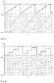
- T 10 discrete phase accumulation values are possible and coded from 0 to 9.
- the corresponding line of the above correspondence matrix indicates a logic level for each of the T logic signals constituting the signal numeric s ⁇ 9: 0>, ordered in columns from s ⁇ 9> to s ⁇ 0>.
- this logic level is binary, the logic signal being either at a first level denoted "0", or at a second level denoted "1".
- each multi-phase correspondence matrix comprises T rows representative of the T discrete possible phase accumulation values and T columns representative of the T logic signals. According to another convention, it could include T columns representative of T discrete possible phase accumulation values and T lines representative of T logic signals. Advantageously, it is symmetrical, so that this convention is completely irrelevant.
- each column of each multi-phase correspondence matrix each column indicating by convention the logic levels that must take one of the T logical signals resulting for the T discrete values of possible phase accumulation, presents circularly by modulo T only one transition from the first binary logic value to the second binary logic value for a first half of the T discrete values of possible phase accumulation and only one transition from the second binary logic value to the first binary logic value for a second half of the T possible discrete phase accumulation values.
- each column differs from that which precedes it or that which follows it only by a shift of a modulo T row of the values of coefficients which it contains, this shift remaining in the same direction from the first to the last column.
- the two digital signals received by the phase comparators 112 of the phase comparison block 110 have a frequency response very close to a straight line which starts from zero frequency and which decreases with frequency.
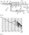
- the figure 5 illustrates, on a logarithmic frequency scale, the frequency response of one of the digital signals resulting from the accumulation of a phase ramp generated by a phase accumulator sampled by a clock signal of frequency F H equal to 1 MHz.
- the spectrum illustrated in this figure is thus parasitized by the frequency F H and its harmonics, a phenomenon well known to those skilled in the art.
- the equivalent sampling carried out by the phase accumulator does not generate spectrum aliasing or quantization noise because it is applied identically to each rising or falling edge of the clock.
- each phase comparator 112 is a linear operation in continuous time
- the spectrum of the result of this operation is a subtraction of the spectra of the two digital signals resulting from the phase accumulation values ( ⁇ ref and ⁇ c without adding additional noise.
- the figure 6 thus illustrates, according to a logarithmic frequency scale, the resulting spectrum at the output of the current summator 116 for the experimental values of the figure 5 .
- the lines of the frequency responses tend to compensate (here at -140 dB).
- the multiplicative factor ⁇ is greater than 1, the first parasitic peak is found at the frequency F ref , whereas in a conventional frequency synthesis device with integer division and frequency dividers, it would be at the frequency F ref / D.
- the phase accumulators 106 and 122 can easily be implemented with means for storing numbers encoded in binary form, in particular for positive integer values such as N and D. They must therefore just provide a sufficient number of bits for perform the arithmetic operations of accumulation of N and D in the set of T possible phase accumulation values. This number n must be greater than or equal to the number of bits necessary to represent, not only N and D, but also T.
- D can go up to 2 31 -1 (same for N), where a conventional integer division frequency synthesizer has values of D limited to 100 or 1000.
- the figure 8 schematically represents a PLL type frequency synthesis device 200, according to a second embodiment of the invention.
- the device 200 also differs from the device 100 in that the second phase accumulator 122 is no longer directly clocked at the output frequency F c , but at the reduced frequency F c / N d which nevertheless remains linked to F c .
- n ENT log 2 MAX NOT at - 1 , D - 1 + 2 .
- N a is less than N, the number of unnecessary implementation bits is reduced.
- the clock frequencies F ref and F c / N d of the two phase accumulators 106 and 122 also become close to each other, that of the second phase accumulator 122 being slowed down so as to further reduce consumption.
- the figure 9 schematically represents a PLL type frequency synthesis device 300, according to a third embodiment of the invention.
- This device 300 differs from device 200 in that each multi-phase converter 108 or 124 is preceded by a device for reducing dynamics by quantization. More precisely, this dynamic reduction is for example carried out using a Delta-Sigma modulation quantizer.
- a first Delta-Sigma modulation quantizer 302 is arranged between the first phase accumulator 106 and the first multi-phase converter 108.
- a second Delta-Sigma modulation quantizer 304 is arranged between the second phase accumulator 122. and the second multi-phase converter 124.
- the dynamic reduction allows a reduction in the number of bits taken into consideration in multi-phase converters, making the number of logic signals that they produce less and the phase comparison block 110 which receives them easier to produce. .
- the simplest solution consists in truncating the values to be converted on a number of bits n 'less than n by removing the least significant bits. .
- This truncation is mathematically equivalent to a new quantization of the digital data.
- This quantization produces an error which is generally assimilated to noise, called quantization noise.
- This noise has a fairly random spectrum but is often approached by a flat spectrum of white noise.
- the multi-phase converters then only need to convert n ′ bits into 2 n ′ logic signals at the cost of parasites which can be assimilated to additional noise in the output spectrum of the frequency synthesis device. Due to the frequency control, this noise is found mainly around the cut-off frequency of the device, its standard deviation decreasing when n 'increases.
- the advantage of using a Delta-Sigma modulation quantizer to achieve the dynamic reduction is to reduce this quantization noise, because the phase comparison block 110 is followed by a low-pass filter, in the This is the loop filter 118.
- the Delta-Sigma modulation function distorts the spectrum of the quantization noise by generating less low-frequency noise and more high-frequency noise close to F ref and F c / N d .
- This noise is then better filtered by the loop filter 118 if the frequencies F ref and F c / N d are sufficiently large compared to the cut-off frequency of the device.
- the order of the filter must be strictly greater than that of the Delta-Sigma modulation.
- the loop filter 118 is therefore at least of order 2, knowing that in addition it cannot be of too high order, that is to say that there remains advantageously d 'order less than or equal to 3.
- a first-order Delta-Sigma modulation quantizer is very simple to implement because it is always stable. It can consist of an adder followed by a register of n bits, the output of which is truncated by taking the n 'most significant bits while the (n - n') remaining low order bits are completed by 0s. in high order values to obtain new data on n input bits. The value of the new data thus created represents the fraction that was truncated at the output of the register. This value is added to the current input data on n bits and the result recorded in the register for the following cycle. This is how the Delta-Sigma modulation quantizer never erases the quantization error, but defers it in time.
- the first chronogram shows the evolution of the phase accumulation values ⁇ ref and ⁇ c whose ramps end up synchronizing before 3.10 -5 seconds.
- the second timing diagram shows the stabilization of the summed current ⁇ l at the output of the current summator 116 at the same time.
- the third timing diagram shows the convergence of the analog voltage V supplied by the loop filter 118 to the oscillator VCO 120 towards a stabilization value at the same time.
- the voltage V 0 is an internal voltage of the loop filter 118 which is indicated in the figure 14 .
- the figure 12 illustrates the same three chronograms in steady state of the frequency synthesis device 100, that is to say from 3.10 -5 seconds, on a finer time scale.
- the small remaining variations correspond to the residual interference of the clock frequencies F ref and F c after filtering by the loop filter 118.
- any of the devices described above can be integrated into any device requiring a synthesis of frequency, such as for example a radiofrequency receiver or transmitter, a timing clock for digital, analog or mixed circuits (ie analog and digital), a clocked measurement system, a time base, etc.
- the figure 13 illustrates an example of a filter of order 1 that can be chosen to produce the loop filter 118 of one or the other of the frequency synthesis devices of the figures 1 and 8 .
- This first-order filter receives at input the summed analog current ⁇ l from the phase comparison block 110 and supplies the analog control voltage V to the oscillator VCO 120 as an output. It also comprises a first capacitive circuit C 0 connecting the input to ground to perform an integration function by inserting a pole at zero frequency (PLL type II). It further comprises a second resistive and capacitive circuit R 1 , C 1 connecting the output to ground to create a phase margin by inserting a zero at low frequency.
- This first order filter cannot be used in the frequency synthesis device of the figure 9 since it cannot be of a strictly higher order than that of the Delta-Sigma quantifiers 302 and 304.
- the figure 14 illustrates an example of a filter of order 2 that can be chosen to produce the loop filter 118 of any one of the frequency synthesis devices of the figures 1 , 8 and 9 .
- This filter of order 2 differs from the filter of the figure 13 in that a third resistive circuit R 2 is interposed between the second circuit R 1 , C 1 and the output, and in that a fourth capacitive circuit C 2 connects the output to ground. These two additional circuits add a pole beyond the filter cutoff frequency.
- the figure 15 schematically represents the general architecture, in terms of logic gates, of an example of phase comparator 112 adapted for the frequency synthesis device of the figure 1 , 8 or 9 .
- This phase comparator comprises a first comparison input which receives one of the T first logic signals supplied by the first multi-phase converter 108.
- This signal is denoted s ref (i), with 0 ⁇ i ⁇ T, and its level logic is updated at frequency F ref .
- the comparator has a second comparison input which receives one of the T second logic signals supplied by the second multi-phase converter 124, more precisely that of the same index as s ref (i).
- This signal is denoted s c (i) and its logic level is updated at the frequency F c (or F c / N d ) -
- the first logic signal s ref (i) is received at the input of a NAND logic gate 400, the output of which is supplied at the input of a NAND logic gate 402 of a first RS flip-flop with two NAND logic gates. AND 402 and 404.
- the output of the NAND logic gate 402 supplies the "up" signal of the phase comparator 112 and is further returned to the input of the NAND logic gate 404.
- the output of the NAND logic gate AND 404 is supplied at the input of a NAND logic gate 406 of a second RS flip-flop with two NAND logic gates 406 and 408 and is further returned at the input of the NAND logic gate 402.
- the output of the logic NAND gate 406 is returned as the input of the logic NAND gate 408.
- the output of the logic NAND gate 408 is returned as the input of the logic NAND gate 406 and is further supplied as the input of the NAND logic gate 400. Finally, the first logic signal s ref (i) is also received at the input of the NAND logic gate 408.
- the second logic signal s c (i) is received at the input of a NAND logic gate 410, the output of which is supplied at the input of a NAND logic gate 412 of a third RS flip-flop with two NAND logic gates. AND 412 and 414.
- the output of the NAND logic gate 412 supplies the "down" signal of the phase comparator 112 and is further returned to the input of the NAND logic gate 414.
- the output of the NAND logic gate AND 414 is supplied at the input of a NAND logic gate 416 of a fourth RS flip-flop with two NAND logic gates 416 and 418 and is further returned at the input of the NAND logic gate 412.
- the output of the NAND logic gate 416 is returned to the input of the NAND logic gate 418.
- the output of the NAND logic gate 418 is returned to the input of the NAND logic gate 416 and is further supplied to the input of the NAND logic gate 410. Finally, the second logic signal s c (i) is also received at the input of the NAND logic gate 418.
- the “up” and “down” signals are further supplied at the input of a NAND logic gate 420, the output of which is provided at the inputs of the NAND logic gates 404 and 414 via a YES logic gate 422 (equivalent to a YES logic gate 422). double NO logic gate).
- the measured phase error is proportional to the width of the pulses generated on the “up” and “down” signals.
- the figure 17 schematically represents the general architecture of an example of charge pump 114 adapted for the frequency synthesis device of the figure 1 , 8 or 9 .
- This current generator I CP 504 supplies a first current mirror 506 with two n-MOS transistors which copies the current I CP on an output n-MOS transistor 508. It also supplies a second current mirror 510 with two p-MOS transistors, one of which, said output, is connected by its drain to the output of the OUI logic gate 500. The drain of the output n-MOS transistor 508 is connected to the output of the NOT logic gate 502. The output current I is taken between the transistor output n-MOS 508 and the output p-MOS transistor of the second current mirror 510.
- the current I CP is copied by the first current mirror 506 on the output n-MOS transistor 508 when it is activated, that is to say when the “down” signal is at level “1”. , and on the output p-MOS transistor of the second current mirror 510 when it is activated, that is to say when the “up” signal is at the “1” level.
- the currents of the output n-MOS and p-MOS transistors cancel each other out at output I.
- the figure 18 schematically represents the general architecture of an example of a phase accumulator 106 or 122 adapted for the frequency synthesis device of the figure 1 or 8 .
- This example is in particular adapted to a precise case according to which the values of phase increments N (or N a ) and D are coded on 4 bits and the registers In, Out occupy 4 bits of memory.
- the input register In stores the configuration value N (or N a ) for the phase accumulator 106 and the configuration value D for the phase accumulator 122.
- This architecture comprises a storage register 600 with four synchronous flip-flops clocked by the clock frequency F H (F ref for the phase accumulator 106 and F c for the phase accumulator 122).
- the four binary outputs of this register 600 supply the four bits Out ⁇ 0>, Out ⁇ 1>, Out ⁇ 2>, Out ⁇ 3> of the Out output register.
- the four binary inputs of this register 600 are supplied by a 4-bit adder 602 with four binary addition modules connected to each other in a conventional manner to carry out an addition on 4 bits.
- the four bits In ⁇ 0>, In ⁇ 1>, In ⁇ 2>, In ⁇ 3> of the input register In supply four respective inputs of the binary addition modules of the adder 602, which also receive the four outputs bits of the storage register 600 to perform the accumulation operation.
- the outputs of the four binary addition modules are supplied to the respective inputs of the four synchronous flip-flops of the storage register 600. Note that the modulo function of each phase accumulator 106, 122 is carried out implicitly by not using the carry-over of the l strong adder.
- each phase accumulator 106 or 122 is thus greatly simplified compared to that which must be considered in the patent document. US 9,509,320 B2 .
- the figure 19 schematically represents the general architecture of an example of phase accumulator 106 or 122 combined with a Delta-Sigma 302 or 304 quantizer, suitable for the frequency synthesis device of the figure 9 .
- This example is in particular suited to the precise case whereby the phase increment values N (or N a ) and D are coded on 4 bits and the register In occupies 4 bits of memory.
- the input register In stores the configuration value N (or N a ) for the phase accumulator 106 and the configuration value D for the phase accumulator 122.
- the phase accumulation function is performed by the storage register 600 and the 4-bit adder 602, arranged as previously in the example of figure 18 .
- the dynamic reduction function using a Delta-Sigma modulation quantizer is performed by an additional 4-bit adder 700 and by an additional storage register 702, these two modules being interposed between the storage register 600 and the output Out reduced to 2 bits.
- the additional adder 700 comprises four binary addition modules connected together in a conventional manner to perform an addition on 4 bits.
- the four output bits of the adder 602 feed four respective inputs of the binary additions modules of the additional adder 700, which also receive either 0's or outputs of the additional storage register 702 as a function of the desired dynamic reduction.
- the two binary addition modules relating to the two most significant bits receive 0s.
- the Out ⁇ 1> bit is determined by the output of the fourth synchronous flip-flop of the additional storage register 702.
- bit Out ⁇ 0> is determined by the output of the third synchronous flip-flop of the additional storage register 702.
- the figure 20 schematically represents the general architecture, in terms of logic gates, of an example of a multi-phase converter 108 or 124 adapted for the frequency synthesis device of the figure 1 , 8 or 9 .
- a NOR logic gate 800 receives the bits ⁇ ⁇ 0> and ⁇ ⁇ 1> to supply a logic value of an intermediate logic signal s A ⁇ 0>.
- a NOT logic gate 802 receives the bit ⁇ ⁇ 1> to provide a logic value of an intermediate logic signal s A ⁇ 1>.
- a logic NAND gate 804 receives the bits ⁇ ⁇ 0> and ⁇ ⁇ 1> to provide a logic value of an intermediate logic signal s A ⁇ 2>.
- a logical value of a signal intermediate logic s A ⁇ 3> is set to "1".
- a logic NOT gate 806 receives the bit ⁇ ⁇ 2>.
- NAND logic gates 808 respectively receive the four logic values of the four intermediate logic signals s A ⁇ 3: 0> and the output of the NAND logic gate 806 to provide respectively four logic values of four intermediate logic signals s B ⁇ 3: 0>.
- NOR logic gates 810 respectively receive the four logic values of the four intermediate logic signals s A ⁇ 3: 0> and the output of the NOT logic gate 806 to respectively provide four logic values of four intermediate logic signals s B ⁇ 7: 4>.
- eight NOR logic gates 812 respectively receive the eight logic values of the eight intermediate logic signals s B ⁇ 7: 0> and the bit ⁇ ⁇ 3> to respectively provide eight logic values of eight intermediate logic signals s C ⁇ 7: 0>.
- Eight NAND logic gates 814 respectively receive the eight logic values of the eight intermediate logic signals s B ⁇ 7: 0> and the bit ⁇ ⁇ 3> to respectively provide eight logic values of eight intermediate logic signals s C ⁇ 15: 8> .
- a logic NOT gate 816 receives the bit ⁇ ⁇ 4>.
- sixteen EXCLUSIVE-OR logic gates 818 respectively receive the sixteen logic values of the sixteen intermediate logic signals s C ⁇ 15: 0> and the bit ⁇ ⁇ 4> to provide respectively the sixteen logic values of the sixteen logic signals s ⁇ 15: 0>.
- Sixteen other EXCLUSIVE-OR logic gates 820 respectively receive the sixteen logic values of the sixteen intermediate logic signals s C ⁇ 15: 0> and the output of the NOT logic gate 816 to provide respectively the sixteen logic values of the sixteen logic signals s ⁇ 31: 16>.
- Oscillator 120 is for example a voltage-controlled oscillator formed of an inductor placed in parallel with two varactors arranged head-to-tail and two NMOS transistors whose gates are mounted head-to-tail so as to generate a gain sufficient to initiate then maintain the oscillation across the inductance, these transistors being polarized thanks to the current coming from the supply of the midpoint of the inductor.
Landscapes
- Stabilization Of Oscillater, Synchronisation, Frequency Synthesizers (AREA)
- Engineering & Computer Science (AREA)
- Power Engineering (AREA)
- Physics & Mathematics (AREA)
- Nonlinear Science (AREA)
Claims (10)
- Vorrichtung (100; 200; 300) zur Frequenzsynthese mit Rückkopplungsschleife, Folgendes beinhaltend:- einen Eingang, der dazu bestimmt ist, ein elektrisches Signal zu empfangen, das auf einer Referenzfrequenz (Fref) oszilliert;- einen Ausgang, der dazu bestimmt ist, ein elektrisches Signal bereitzustellen, das auf einer Ausgangsfrequenz (Fc) oszilliert;- eine Schaltung (102) zum Unterwerfen der Ausgangsfrequenz (Fc) auf die Referenzfrequenz (Fref), die den Eingang mit dem Ausgang der Vorrichtung verbindet, und einen ersten Phasenakkumulator (106) beinhaltet, der auf eine mit der Referenzfrequenz (Fref) verknüpfte Frequenz getaktet ist, einen Phasenvergleichsblock (110), einen Schleifenfilter (118) und einen Oszillator (120) mit kontrollierter Frequenz, der das elektrische Signal bereitstellt, das auf der Ausgangsfrequenz (Fc) oszilliert, wobei der Phasenvergleichsblock (110) mit dem Schleifenfilter verknüpft ist, um den Oszillator (120) mit kontrollierter Frequenz zu kontrollieren; und- eine Rückkopplungsschleife (104), die den Ausgang mit dem Phasenvergleichsblock (110) verknüpft, die einen zweiten Phasenakkumulator (122) beinhaltet, der auf eine mit der Ausgangsfrequenz (Fc) verknüpfte Frequenz getaktet ist, wobei der erste und zweite Phasenakkumulator (106, 122) imstande sind, eine selbe Anzahl T an möglichen diskreten Phasenakkumulationswerten bereitzustellen;dadurch gekennzeichnet, dass:- die Schaltung zum Unterwerfen (102) konfiguriert ist, um dem Phasenvergleichsblock (110) T erste unterschiedliche logische Signale bereitzustellen, deren Logikpegel kontinuierlich von den Phasenakkumulationswerten (ϕref) abhängig sind, die von dem ersten Phasenakkumulator (106) gemäß einer ersten Mehrphasen-Korrespondenz-Matrix zwischen den T möglichen diskreten Phasenakkumulationswerten und den T ersten Signalen bereitgestellt werden;- die Rückkopplungsschleife (104) konfiguriert ist, um dem Phasenvergleichsblock (110) T zweite unterschiedliche logische Signale bereitzustellen, deren Logikpegel kontinuierlich von den Phasenakkumulationswerten (ϕc) abhängig sind, die von dem zweiten Phasenakkumulator (122) gemäß einer zweiten Mehrphasen-Korrespondenz-Matrix zwischen den T möglichen diskreten Phasenakkumulationswerten und den T zweiten Signalen bereitgestellt werden;
und- der Phasenvergleichsblock (110) T Phasenvergleicher (112) mit Logikgattern beinhaltet, die jeweils in kontinuierlicher Zeit die T ersten logischen Signale in T ersten Vergleichseingängen und die T zweiten logischen Signale in T zweiten Vergleichseingängen empfangen. - Vorrichtung (100; 200; 300) zur Frequenzsynthese nach Anspruch 1, wobei:- die Schaltung zum Unterwerfen (102) einen ersten Mehrphasenwandler (108) zwischen dem ersten Phasenakkumulator (106) und dem Phasenvergleichsblock (110) beinhaltet, der konfiguriert ist, um die erste Mehrphasen-Korrespondenz-Matrix zu implementieren; und- die Rückkopplungsschleife (104) einen zweiten Mehrphasenwandler (124) zwischen dem zweiten Phasenakkumulator (122) und dem Phasenvergleichsblock (110) beinhaltet, der konfiguriert ist, um die zweite Mehrphasen-Korrespondenz-Matrix zu implementieren.
- Vorrichtung (100; 200; 300) zur Frequenzsynthese nach Anspruch 2, wobei jeder des ersten und zweiten Mehrphasenwandlers (108, 124) seine Mehrphasen-Korrespondenz-Matrix in Form einer Logikgattereinheit (800 bis 820) implementiert, die am Eingang einen laufenden Phasenakkumulationswert empfängt, der binär auf In(T)/In(2) Bits codiert ist, wobei In(.) die natürliche Logarithmusfunktion ist, und am Ausgang T laufende Logikpegelwerte bereitstellt.
- Vorrichtung (100; 200; 300) zur Frequenzsynthese nach einem der Ansprüche 1 bis 3, wobei jeder Koeffizient jeder der ersten und zweiten Mehrphasen-Korrespondenz-Matrizen entweder auf einem ersten binären Wert ist, der auf einen ersten Logikpegel eines logischen Signals hinweist, oder auf einem zweiten binären Wert, der auf einen zweiten Logikpegel eines logischen Signals hinweist.
- Vorrichtung (100; 200; 300) zur Frequenzsynthese nach Anspruch 4, wobei jede Zeile oder Spalte jeder der ersten und zweiten Mehrphasen-Korrespondenz-Matrizen, wenn diese Zeile oder Spalte auf die Logikpegel hinweist, die eines der ersten oder zweiten T logischen Signale für die möglichen T diskreten Phasenakkumulationswerte einnehmen muss, kreisförmig durch modulo T nur einen einzigen Übergang von dem ersten binären Wert auf den zweiten binären Wert für eine erste Hälfte der T möglichen diskreten Phasenakkumulationswerte, und nur einen einzigen Übergang von dem zweiten binären Wert auf den ersten binären Wert für eine zweite Hälfte der T möglichen diskreten Phasenakkumulationswerte aufweist.
- Vorrichtung (100; 200; 300) zur Frequenzsynthese nach Anspruch 4 oder 5, wobei jede Zeile oder Spalte jeder der ersten und zweiten Mehrphasen-Korrespondenz-Matrizen, wenn diese Zeile oder Spalte auf die Logikpegel hinweist, den eines der ersten oder zweiten T logischen Signale für die möglichen T diskreten Phasenakkumulationswerte einnehmen muss, von jenem, der ihm vorausgeht oder jenem, der ihm nachfolgt, nur um den Versatz einer Spalte, oder jeweils um eine Zeile modulo T der Koeffizienten-Werte, die sie enthält, abweicht, wobei dieser Versatz in derselben Richtung von der ersten bis zur letzten Zeile oder Spalte verbleibt.
- Vorrichtung (100; 200; 300) zur Frequenzsynthese nach einem der Ansprüche 1 bis 6, wobei jede der ersten und zweiten Korrespondenz-Matrizen symmetrisch ist.
- Vorrichtung (100; 200; 300) zur Frequenzsynthese nach einem der Ansprüche 1 bis 7, wobei die erste und zweite Korrespondenz-Matrizen identisch sind.
- Vorrichtung (100; 200; 300) zur Frequenzsynthese nach einem der Ansprüche 1 bis 8, wobei der Phasenvergleichsblock (110) T Ladepumpen (114) beinhaltet, die jeweils in kontinuierlicher Zeit T Impulssignalpaare empfängt, die von den T Phasenvergleichern (112) bereitgestellt werden, und jeweils in kontinuierlicher Zeit T Ausgangsströme bereitstellt.
- Vorrichtung (100; 200; 300) zur Frequenzsynthese nach Anspruch 9, wobei der Phasenvergleichsblock (110) einen Summierer von Strömen (116) beinhaltet, der parallel die T Ausgangsströme empfängt, die die von den T Ladepumpen (114) bereitgestellt werden, um einen einzigen Strom bereitzustellen, der am Ausgang des Phasenvergleichsblocks (110) summiert wird.
Applications Claiming Priority (1)
| Application Number | Priority Date | Filing Date | Title |
|---|---|---|---|
| FR1907587A FR3098664B1 (fr) | 2019-07-08 | 2019-07-08 | Dispositif de synthèse de fréquence à boucle de rétroaction |
Publications (2)
| Publication Number | Publication Date |
|---|---|
| EP3764546A1 EP3764546A1 (de) | 2021-01-13 |
| EP3764546B1 true EP3764546B1 (de) | 2021-06-30 |
Family
ID=68806888
Family Applications (1)
| Application Number | Title | Priority Date | Filing Date |
|---|---|---|---|
| EP20181049.6A Active EP3764546B1 (de) | 2019-07-08 | 2020-06-19 | Vorrichtung zur frequenzsynthese mit rückkopplungsschleife |
Country Status (3)
| Country | Link |
|---|---|
| US (1) | US11095292B2 (de) |
| EP (1) | EP3764546B1 (de) |
| FR (1) | FR3098664B1 (de) |
Families Citing this family (1)
| Publication number | Priority date | Publication date | Assignee | Title |
|---|---|---|---|---|
| WO2021150150A1 (en) * | 2020-01-21 | 2021-07-29 | Telefonaktiebolaget Lm Ericsson (Publ) | Phase locked loop circuit with increased robustness |
Family Cites Families (10)
| Publication number | Priority date | Publication date | Assignee | Title |
|---|---|---|---|---|
| JP2825045B2 (ja) * | 1992-08-05 | 1998-11-18 | 日本電気株式会社 | 周波数シンセサイザ |
| FR2763196B1 (fr) | 1997-05-07 | 1999-07-30 | Thomson Csf | Synthetiseur de frequence coherent a boucle de phase et pas fractionnaires |
| DE19727810C1 (de) * | 1997-06-30 | 1999-02-18 | Siemens Ag | Hochfrequenz-Signalgenerator |
| US7425851B2 (en) * | 2002-06-19 | 2008-09-16 | R & C Holding Aps | Phase-locked loop with incremental phase detectors and a converter for combining a logical operation with a digital to analog conversion |
| US20090085674A1 (en) * | 2007-09-28 | 2009-04-02 | Ahmadreza Rofougaran | Method and system for signal generation via a pll with digital phase detection |
| FI120524B (fi) | 2007-10-25 | 2009-11-13 | Teknillinen Korkeakoulu | Vaiheakku digitaalista vaihelukittua silmukkaa varten |
| KR101101447B1 (ko) | 2009-12-04 | 2012-01-03 | 한국과학기술원 | 루프지연을 개선한 디지털 위상고정루프 |
| KR101206436B1 (ko) * | 2010-09-29 | 2012-11-29 | 전자부품연구원 | 위상 동기 루프 기반의 주파수 합성기 및 그의 동작 방법 |
| FR3032072B1 (fr) | 2015-01-23 | 2018-05-11 | Commissariat A L'energie Atomique Et Aux Energies Alternatives | Dispositif de synthese de frequence a boucle de retroaction |
| EP3618281B1 (de) * | 2018-09-03 | 2023-05-10 | IHP GmbH - Innovations for High Performance Microelectronics / Leibniz-Institut für innovative Mikroelektronik | Paralleler fractional-n-phasenregelkreis |
-
2019
- 2019-07-08 FR FR1907587A patent/FR3098664B1/fr not_active Expired - Fee Related
-
2020
- 2020-06-19 EP EP20181049.6A patent/EP3764546B1/de active Active
- 2020-07-07 US US16/922,750 patent/US11095292B2/en active Active
Also Published As
| Publication number | Publication date |
|---|---|
| US20210013890A1 (en) | 2021-01-14 |
| EP3764546A1 (de) | 2021-01-13 |
| US11095292B2 (en) | 2021-08-17 |
| FR3098664A1 (fr) | 2021-01-15 |
| FR3098664B1 (fr) | 2021-07-23 |
Similar Documents
| Publication | Publication Date | Title |
|---|---|---|
| EP1624575B1 (de) | Frequenzsynthetiser Architektur | |
| EP1956714B1 (de) | Verfahren zum Hinzufügen eines zufallsbedingten Rauschens in einen Zeit-Digital-Wandlungsschaltkreis und Schaltkreise zur Umsetzung des Verfahrens | |
| EP2137873B1 (de) | Vorrichtung zur rückgewinnung des taktsignales zur digitalen regelung der phase ohne externe regelung | |
| EP0142440A2 (de) | Vorrichtung zum Erzeugen einer, bezüglich einer Referenzfrequenz gebrochenen Frequenz | |
| FR2687522A1 (fr) | Synthetiseur de frequence a nombre n fractionnaire employant plusieurs accumulateurs avec recombinaison en serie, procede de mise en óoeuvre, et radiotelephone l'utilisant. | |
| FR2666464A1 (fr) | Procede et appareil de synthese de frequence a n fractionnaire avec accumulateurs multiples a memorisation temporaire et application a un radioemetteur. | |
| FR2815194A1 (fr) | Synthetiseur de frequence fractionnel n module sigma/delta a bit unique | |
| EP1367723B1 (de) | Digitaler Sigma-Delta Modulator und Digitaler Frequenzsynthetisierer mit einem solchen Modulator | |
| EP1193878B1 (de) | Frequenzsynthesizer und Verfahren zur Frequenzsynthese mit geringem Rauschen | |
| EP3048730B1 (de) | Vorrichtung zur erzeugung einer rückkopplungsschleifenfrequenz | |
| EP3276833A1 (de) | Sigma-delta-wandler mit hoher linearität | |
| EP3764546B1 (de) | Vorrichtung zur frequenzsynthese mit rückkopplungsschleife | |
| FR3086131A1 (fr) | Dispositif de reglage du verrouillage d'un multiplicateur de frequence a verrouillage par injection | |
| FR2713034A1 (fr) | Circuit de récupération d'horloge à oscillateurs appariés. | |
| EP0147307A2 (de) | Frequenzsynthesierer mit gebrochenem Teilungsverhältnis und mit schwachem Phasenrauschen und Anwendung dieser Synthesierer | |
| EP1193877A1 (de) | Frequenzsynthesizer mit gebrochenem Teilverhältnis und schneller Abstimmung und entsprechendes Verfahren zur Frequenzsynthese | |
| EP1710916B1 (de) | Phasenregelschleife | |
| EP1193879A1 (de) | Rauscharmer und schnellansprechender Frequenzsynthesierer, und übereinstimmendes Verfahren zur Frequenzsynthese | |
| EP0077589B1 (de) | Frequenzsynthesator mit schneller Abstimmung | |
| EP1133060B1 (de) | Phasenregelschleife zur Erzeugung eines Referenzsignals hoher spektraler Reinheit | |
| EP1133059B1 (de) | Frequenzumwandler, welcher Programmierung eines nicht ganzzahligen Teilerverhältnisses ermöglicht durch ein einzelnes Steuerwort | |
| FR2816075A1 (fr) | Generateur ameliore pour la production de signaux d'horloge | |
| WO2008046741A1 (fr) | Synthetiseur de frequence a large bande a suppression d'emissions parasites basses frequences | |
| FR3102625A1 (fr) | Dispositif NFC émulé en mode carte comprenant une boucle à verrouillage de phase numérique, et procédé de communication correspondant. | |
| FR2624673A1 (fr) | Oscillateur a commande numerique, utilisant un element commutable, application a la realisation de dispositifs de recuperation du rythme et de la phase d'un signal numerique |
Legal Events
| Date | Code | Title | Description |
|---|---|---|---|
| PUAI | Public reference made under article 153(3) epc to a published international application that has entered the european phase |
Free format text: ORIGINAL CODE: 0009012 |
|
| STAA | Information on the status of an ep patent application or granted ep patent |
Free format text: STATUS: REQUEST FOR EXAMINATION WAS MADE |
|
| 17P | Request for examination filed |
Effective date: 20200619 |
|
| AK | Designated contracting states |
Kind code of ref document: A1 Designated state(s): AL AT BE BG CH CY CZ DE DK EE ES FI FR GB GR HR HU IE IS IT LI LT LU LV MC MK MT NL NO PL PT RO RS SE SI SK SM TR |
|
| AX | Request for extension of the european patent |
Extension state: BA ME |
|
| GRAP | Despatch of communication of intention to grant a patent |
Free format text: ORIGINAL CODE: EPIDOSNIGR1 |
|
| STAA | Information on the status of an ep patent application or granted ep patent |
Free format text: STATUS: GRANT OF PATENT IS INTENDED |
|
| RIC1 | Information provided on ipc code assigned before grant |
Ipc: H03L 7/18 20060101AFI20210223BHEP Ipc: H03L 7/087 20060101ALI20210223BHEP |
|
| INTG | Intention to grant announced |
Effective date: 20210325 |
|
| GRAS | Grant fee paid |
Free format text: ORIGINAL CODE: EPIDOSNIGR3 |
|
| GRAA | (expected) grant |
Free format text: ORIGINAL CODE: 0009210 |
|
| STAA | Information on the status of an ep patent application or granted ep patent |
Free format text: STATUS: THE PATENT HAS BEEN GRANTED |
|
| AK | Designated contracting states |
Kind code of ref document: B1 Designated state(s): AL AT BE BG CH CY CZ DE DK EE ES FI FR GB GR HR HU IE IS IT LI LT LU LV MC MK MT NL NO PL PT RO RS SE SI SK SM TR |
|
| REG | Reference to a national code |
Ref country code: CH Ref legal event code: EP |
|
| REG | Reference to a national code |
Ref country code: AT Ref legal event code: REF Ref document number: 1407323 Country of ref document: AT Kind code of ref document: T Effective date: 20210715 |
|
| REG | Reference to a national code |
Ref country code: DE Ref legal event code: R096 Ref document number: 602020000206 Country of ref document: DE |
|
| REG | Reference to a national code |
Ref country code: IE Ref legal event code: FG4D Free format text: LANGUAGE OF EP DOCUMENT: FRENCH |
|
| REG | Reference to a national code |
Ref country code: LT Ref legal event code: MG9D |
|
| PG25 | Lapsed in a contracting state [announced via postgrant information from national office to epo] |
Ref country code: BG Free format text: LAPSE BECAUSE OF FAILURE TO SUBMIT A TRANSLATION OF THE DESCRIPTION OR TO PAY THE FEE WITHIN THE PRESCRIBED TIME-LIMIT Effective date: 20210930 Ref country code: FI Free format text: LAPSE BECAUSE OF FAILURE TO SUBMIT A TRANSLATION OF THE DESCRIPTION OR TO PAY THE FEE WITHIN THE PRESCRIBED TIME-LIMIT Effective date: 20210630 Ref country code: HR Free format text: LAPSE BECAUSE OF FAILURE TO SUBMIT A TRANSLATION OF THE DESCRIPTION OR TO PAY THE FEE WITHIN THE PRESCRIBED TIME-LIMIT Effective date: 20210630 |
|
| REG | Reference to a national code |
Ref country code: NL Ref legal event code: MP Effective date: 20210630 |
|
| REG | Reference to a national code |
Ref country code: AT Ref legal event code: MK05 Ref document number: 1407323 Country of ref document: AT Kind code of ref document: T Effective date: 20210630 |
|
| PG25 | Lapsed in a contracting state [announced via postgrant information from national office to epo] |
Ref country code: GR Free format text: LAPSE BECAUSE OF FAILURE TO SUBMIT A TRANSLATION OF THE DESCRIPTION OR TO PAY THE FEE WITHIN THE PRESCRIBED TIME-LIMIT Effective date: 20211001 Ref country code: LV Free format text: LAPSE BECAUSE OF FAILURE TO SUBMIT A TRANSLATION OF THE DESCRIPTION OR TO PAY THE FEE WITHIN THE PRESCRIBED TIME-LIMIT Effective date: 20210630 Ref country code: NO Free format text: LAPSE BECAUSE OF FAILURE TO SUBMIT A TRANSLATION OF THE DESCRIPTION OR TO PAY THE FEE WITHIN THE PRESCRIBED TIME-LIMIT Effective date: 20210930 Ref country code: RS Free format text: LAPSE BECAUSE OF FAILURE TO SUBMIT A TRANSLATION OF THE DESCRIPTION OR TO PAY THE FEE WITHIN THE PRESCRIBED TIME-LIMIT Effective date: 20210630 Ref country code: SE Free format text: LAPSE BECAUSE OF FAILURE TO SUBMIT A TRANSLATION OF THE DESCRIPTION OR TO PAY THE FEE WITHIN THE PRESCRIBED TIME-LIMIT Effective date: 20210630 |
|
| PG25 | Lapsed in a contracting state [announced via postgrant information from national office to epo] |
Ref country code: AT Free format text: LAPSE BECAUSE OF FAILURE TO SUBMIT A TRANSLATION OF THE DESCRIPTION OR TO PAY THE FEE WITHIN THE PRESCRIBED TIME-LIMIT Effective date: 20210630 Ref country code: CZ Free format text: LAPSE BECAUSE OF FAILURE TO SUBMIT A TRANSLATION OF THE DESCRIPTION OR TO PAY THE FEE WITHIN THE PRESCRIBED TIME-LIMIT Effective date: 20210630 Ref country code: PT Free format text: LAPSE BECAUSE OF FAILURE TO SUBMIT A TRANSLATION OF THE DESCRIPTION OR TO PAY THE FEE WITHIN THE PRESCRIBED TIME-LIMIT Effective date: 20211102 Ref country code: NL Free format text: LAPSE BECAUSE OF FAILURE TO SUBMIT A TRANSLATION OF THE DESCRIPTION OR TO PAY THE FEE WITHIN THE PRESCRIBED TIME-LIMIT Effective date: 20210630 Ref country code: RO Free format text: LAPSE BECAUSE OF FAILURE TO SUBMIT A TRANSLATION OF THE DESCRIPTION OR TO PAY THE FEE WITHIN THE PRESCRIBED TIME-LIMIT Effective date: 20210630 Ref country code: SM Free format text: LAPSE BECAUSE OF FAILURE TO SUBMIT A TRANSLATION OF THE DESCRIPTION OR TO PAY THE FEE WITHIN THE PRESCRIBED TIME-LIMIT Effective date: 20210630 Ref country code: SK Free format text: LAPSE BECAUSE OF FAILURE TO SUBMIT A TRANSLATION OF THE DESCRIPTION OR TO PAY THE FEE WITHIN THE PRESCRIBED TIME-LIMIT Effective date: 20210630 Ref country code: EE Free format text: LAPSE BECAUSE OF FAILURE TO SUBMIT A TRANSLATION OF THE DESCRIPTION OR TO PAY THE FEE WITHIN THE PRESCRIBED TIME-LIMIT Effective date: 20210630 Ref country code: ES Free format text: LAPSE BECAUSE OF FAILURE TO SUBMIT A TRANSLATION OF THE DESCRIPTION OR TO PAY THE FEE WITHIN THE PRESCRIBED TIME-LIMIT Effective date: 20210630 |
|
| PG25 | Lapsed in a contracting state [announced via postgrant information from national office to epo] |
Ref country code: PL Free format text: LAPSE BECAUSE OF FAILURE TO SUBMIT A TRANSLATION OF THE DESCRIPTION OR TO PAY THE FEE WITHIN THE PRESCRIBED TIME-LIMIT Effective date: 20210630 |
|
| REG | Reference to a national code |
Ref country code: DE Ref legal event code: R097 Ref document number: 602020000206 Country of ref document: DE |
|
| PG25 | Lapsed in a contracting state [announced via postgrant information from national office to epo] |
Ref country code: DK Free format text: LAPSE BECAUSE OF FAILURE TO SUBMIT A TRANSLATION OF THE DESCRIPTION OR TO PAY THE FEE WITHIN THE PRESCRIBED TIME-LIMIT Effective date: 20210630 |
|
| PLBE | No opposition filed within time limit |
Free format text: ORIGINAL CODE: 0009261 |
|
| STAA | Information on the status of an ep patent application or granted ep patent |
Free format text: STATUS: NO OPPOSITION FILED WITHIN TIME LIMIT |
|
| PG25 | Lapsed in a contracting state [announced via postgrant information from national office to epo] |
Ref country code: AL Free format text: LAPSE BECAUSE OF FAILURE TO SUBMIT A TRANSLATION OF THE DESCRIPTION OR TO PAY THE FEE WITHIN THE PRESCRIBED TIME-LIMIT Effective date: 20210630 |
|
| 26N | No opposition filed |
Effective date: 20220331 |
|
| PG25 | Lapsed in a contracting state [announced via postgrant information from national office to epo] |
Ref country code: IT Free format text: LAPSE BECAUSE OF FAILURE TO SUBMIT A TRANSLATION OF THE DESCRIPTION OR TO PAY THE FEE WITHIN THE PRESCRIBED TIME-LIMIT Effective date: 20210630 |
|
| PG25 | Lapsed in a contracting state [announced via postgrant information from national office to epo] |
Ref country code: MC Free format text: LAPSE BECAUSE OF FAILURE TO SUBMIT A TRANSLATION OF THE DESCRIPTION OR TO PAY THE FEE WITHIN THE PRESCRIBED TIME-LIMIT Effective date: 20210630 |
|
| REG | Reference to a national code |
Ref country code: BE Ref legal event code: MM Effective date: 20220630 |
|
| PG25 | Lapsed in a contracting state [announced via postgrant information from national office to epo] |
Ref country code: LU Free format text: LAPSE BECAUSE OF NON-PAYMENT OF DUE FEES Effective date: 20220619 Ref country code: LT Free format text: LAPSE BECAUSE OF FAILURE TO SUBMIT A TRANSLATION OF THE DESCRIPTION OR TO PAY THE FEE WITHIN THE PRESCRIBED TIME-LIMIT Effective date: 20210630 Ref country code: IE Free format text: LAPSE BECAUSE OF NON-PAYMENT OF DUE FEES Effective date: 20220619 |
|
| PG25 | Lapsed in a contracting state [announced via postgrant information from national office to epo] |
Ref country code: BE Free format text: LAPSE BECAUSE OF NON-PAYMENT OF DUE FEES Effective date: 20220630 |
|
| REG | Reference to a national code |
Ref country code: CH Ref legal event code: PL |
|
| PG25 | Lapsed in a contracting state [announced via postgrant information from national office to epo] |
Ref country code: MK Free format text: LAPSE BECAUSE OF FAILURE TO SUBMIT A TRANSLATION OF THE DESCRIPTION OR TO PAY THE FEE WITHIN THE PRESCRIBED TIME-LIMIT Effective date: 20210630 Ref country code: CY Free format text: LAPSE BECAUSE OF FAILURE TO SUBMIT A TRANSLATION OF THE DESCRIPTION OR TO PAY THE FEE WITHIN THE PRESCRIBED TIME-LIMIT Effective date: 20210630 Ref country code: CH Free format text: LAPSE BECAUSE OF NON-PAYMENT OF DUE FEES Effective date: 20230630 |
|
| PG25 | Lapsed in a contracting state [announced via postgrant information from national office to epo] |
Ref country code: HU Free format text: LAPSE BECAUSE OF FAILURE TO SUBMIT A TRANSLATION OF THE DESCRIPTION OR TO PAY THE FEE WITHIN THE PRESCRIBED TIME-LIMIT; INVALID AB INITIO Effective date: 20200619 |
|
| PG25 | Lapsed in a contracting state [announced via postgrant information from national office to epo] |
Ref country code: TR Free format text: LAPSE BECAUSE OF FAILURE TO SUBMIT A TRANSLATION OF THE DESCRIPTION OR TO PAY THE FEE WITHIN THE PRESCRIBED TIME-LIMIT Effective date: 20210630 |
|
| PGFP | Annual fee paid to national office [announced via postgrant information from national office to epo] |
Ref country code: DE Payment date: 20240617 Year of fee payment: 5 |
|
| PGFP | Annual fee paid to national office [announced via postgrant information from national office to epo] |
Ref country code: FR Payment date: 20240627 Year of fee payment: 5 |
|
| PG25 | Lapsed in a contracting state [announced via postgrant information from national office to epo] |
Ref country code: MT Free format text: LAPSE BECAUSE OF FAILURE TO SUBMIT A TRANSLATION OF THE DESCRIPTION OR TO PAY THE FEE WITHIN THE PRESCRIBED TIME-LIMIT Effective date: 20210630 |