EP3764546B1 - Frequency synthesis device with feedback loop - Google Patents
Frequency synthesis device with feedback loop Download PDFInfo
- Publication number
- EP3764546B1 EP3764546B1 EP20181049.6A EP20181049A EP3764546B1 EP 3764546 B1 EP3764546 B1 EP 3764546B1 EP 20181049 A EP20181049 A EP 20181049A EP 3764546 B1 EP3764546 B1 EP 3764546B1
- Authority
- EP
- European Patent Office
- Prior art keywords
- phase
- frequency
- logic
- output
- values
- Prior art date
- Legal status (The legal status is an assumption and is not a legal conclusion. Google has not performed a legal analysis and makes no representation as to the accuracy of the status listed.)
- Active
Links
- 230000015572 biosynthetic process Effects 0.000 title claims description 54
- 238000003786 synthesis reaction Methods 0.000 title claims description 54
- 238000009825 accumulation Methods 0.000 claims description 63
- 239000011159 matrix material Substances 0.000 claims description 22
- 230000007704 transition Effects 0.000 claims description 6
- 230000035508 accumulation Effects 0.000 description 53
- 238000001228 spectrum Methods 0.000 description 20
- 230000006870 function Effects 0.000 description 18
- 238000013139 quantization Methods 0.000 description 15
- 238000007792 addition Methods 0.000 description 14
- 235000021183 entrée Nutrition 0.000 description 11
- 230000009467 reduction Effects 0.000 description 10
- 230000000737 periodic effect Effects 0.000 description 9
- 230000001360 synchronised effect Effects 0.000 description 9
- 238000010586 diagram Methods 0.000 description 8
- 230000003071 parasitic effect Effects 0.000 description 8
- 238000006243 chemical reaction Methods 0.000 description 7
- 230000004044 response Effects 0.000 description 5
- 230000003595 spectral effect Effects 0.000 description 5
- 230000001052 transient effect Effects 0.000 description 5
- 230000008901 benefit Effects 0.000 description 4
- 239000013256 coordination polymer Substances 0.000 description 4
- 244000045947 parasite Species 0.000 description 4
- 238000004364 calculation method Methods 0.000 description 3
- 230000008859 change Effects 0.000 description 3
- 230000000875 corresponding effect Effects 0.000 description 3
- 238000013461 design Methods 0.000 description 3
- 229920000729 poly(L-lysine) polymer Polymers 0.000 description 3
- 230000000630 rising effect Effects 0.000 description 3
- 230000015556 catabolic process Effects 0.000 description 2
- 230000007423 decrease Effects 0.000 description 2
- 238000006731 degradation reaction Methods 0.000 description 2
- 230000001419 dependent effect Effects 0.000 description 2
- 230000006872 improvement Effects 0.000 description 2
- 230000006641 stabilisation Effects 0.000 description 2
- 238000011105 stabilization Methods 0.000 description 2
- 230000002123 temporal effect Effects 0.000 description 2
- 238000012546 transfer Methods 0.000 description 2
- 239000000470 constituent Substances 0.000 description 1
- 230000002596 correlated effect Effects 0.000 description 1
- 230000003247 decreasing effect Effects 0.000 description 1
- 230000003111 delayed effect Effects 0.000 description 1
- 230000002542 deteriorative effect Effects 0.000 description 1
- 230000001627 detrimental effect Effects 0.000 description 1
- 238000001914 filtration Methods 0.000 description 1
- 230000010354 integration Effects 0.000 description 1
- 238000005259 measurement Methods 0.000 description 1
- 230000007246 mechanism Effects 0.000 description 1
- 238000000034 method Methods 0.000 description 1
- 238000012986 modification Methods 0.000 description 1
- 230000004048 modification Effects 0.000 description 1
- 230000010355 oscillation Effects 0.000 description 1
- 230000008569 process Effects 0.000 description 1
- 230000001902 propagating effect Effects 0.000 description 1
- 238000011002 quantification Methods 0.000 description 1
- 239000010453 quartz Substances 0.000 description 1
- 230000009257 reactivity Effects 0.000 description 1
- 238000005070 sampling Methods 0.000 description 1
- VYPSYNLAJGMNEJ-UHFFFAOYSA-N silicon dioxide Inorganic materials O=[Si]=O VYPSYNLAJGMNEJ-UHFFFAOYSA-N 0.000 description 1
Images


Classifications
-
- H—ELECTRICITY
- H03—ELECTRONIC CIRCUITRY
- H03L—AUTOMATIC CONTROL, STARTING, SYNCHRONISATION, OR STABILISATION OF GENERATORS OF ELECTRONIC OSCILLATIONS OR PULSES
- H03L7/00—Automatic control of frequency or phase; Synchronisation
- H03L7/06—Automatic control of frequency or phase; Synchronisation using a reference signal applied to a frequency- or phase-locked loop
- H03L7/08—Details of the phase-locked loop
- H03L7/085—Details of the phase-locked loop concerning mainly the frequency- or phase-detection arrangement including the filtering or amplification of its output signal
- H03L7/087—Details of the phase-locked loop concerning mainly the frequency- or phase-detection arrangement including the filtering or amplification of its output signal using at least two phase detectors or a frequency and phase detector in the loop
-
- H—ELECTRICITY
- H03—ELECTRONIC CIRCUITRY
- H03L—AUTOMATIC CONTROL, STARTING, SYNCHRONISATION, OR STABILISATION OF GENERATORS OF ELECTRONIC OSCILLATIONS OR PULSES
- H03L7/00—Automatic control of frequency or phase; Synchronisation
- H03L7/06—Automatic control of frequency or phase; Synchronisation using a reference signal applied to a frequency- or phase-locked loop
- H03L7/16—Indirect frequency synthesis, i.e. generating a desired one of a number of predetermined frequencies using a frequency- or phase-locked loop
- H03L7/18—Indirect frequency synthesis, i.e. generating a desired one of a number of predetermined frequencies using a frequency- or phase-locked loop using a frequency divider or counter in the loop
- H03L7/1806—Indirect frequency synthesis, i.e. generating a desired one of a number of predetermined frequencies using a frequency- or phase-locked loop using a frequency divider or counter in the loop the frequency divider comprising a phase accumulator generating the frequency divided signal
Definitions
- the present invention relates to a feedback loop frequency synthesis device.
- phase locked loops known as PLL (from the English “Phase Locked Loop”), generally called phase locked loops.
- the frequency-controlled oscillator for example of the VCO (“Voltage Controlled Oscillator”), DCO (“Digitally Controlled Oscillator”) or other type, is controlled by a digital value, a voltage or a analog current, or even a combination of an analog value and a digital value. Although this is usually not the case, the transfer function of such an oscillator is often considered linear and simply represented by a conversion factor K.
- the phase comparison block generally operates on signal edges to be compared, that is to say when these signals reach the same value at the same slope.
- the phase comparison then itself provides one or more signals which represent the phase difference between the edges of the compared signals.
- the signals resulting from the comparison are transformed into a single current or voltage pulse signal by a charge pump.
- This current (or voltage) is of constant amplitude I (or U), it takes the sign of the phase difference and its pulse has a width proportional to the phase difference.
- the phase comparison block can be implemented more or less analog or digital.
- the impulse supplied by the charge pump is then filtered by the loop filter which is based on the impulse response of an integrating filter.
- the loop filter can also be produced in a more or less analog or digital fashion.
- the control of the oscillator is indeed proportional to a frequency which will tend towards the desired frequency at the output as and when that the phase difference with the reference signal will tend towards 0 or towards another constant value.
- PLLs are thus generally used in electronic circuits as sources of high frequencies. Indeed, these devices allow from a low frequency source and high spectral purity (for example quartz emitting periodic signals at a few MHz) to obtain periodic signals at high frequency (for example a few GHz) and with spectral purity of better quality than devices directly generating high frequency signals.
- spectral purity for example quartz emitting periodic signals at a few MHz
- high frequency for example a few GHz
- An important parameter of frequency synthesis devices is the time ⁇ t for establishing their operating regime, that is to say the time that they take to be operational, either at start-up or during a change of channel (ie change in factor a).
- This time ⁇ t continues during a transient regime, generally referred to as a latching phase, preceding the operating regime.
- a transient regime generally referred to as a latching phase
- the transient regime of synthesized frequency follows an envelope exponential tending asymptotically towards F ' c at a natural resonant frequency ⁇ for the duration ⁇ t.
- the duration ⁇ t of the latching phase depends on the constituent parameters of a frequency synthesis device and limits its reactivity.
- Another important parameter of frequency synthesis devices is the resolution of possible variations of the multiplying factor ⁇ and therefore the possible fineness of adjustment of the output frequency F c as a function of the targeted applications or standards.
- phase noise from the English "spurious signais"
- power consumption from the English "spurious signais”
- the multiplicative factor ⁇ is chosen as the quotient of two integer values N and D where the value N is generally greater than D.
- a frequency divider of factor D is arranged in the servo circuit between the input and a first comparison input of a comparator of the phase comparison block, while a frequency divider factor N is disposed in the feedback loop between the output, which corresponds to the output of the frequency controlled oscillator, and a second comparison input of the phase comparator.
- the contributions to the phase noise induced at the output also depend directly on the cut-off frequency of the PLL.
- the noise is dominated by the contribution of the reference signal.
- multiplied by a it is generally less than that provided by the PLL itself. It may thus be preferable to increase the cut-off frequency of the PLL in order to lower the phase noise in the lower part of the spectrum obtained at the output. But in this case, it is to the detriment of the value of D. Therefore, jointly optimizing the phase noise and the resolution of possible variations of the multiplying factor a, is impossible to achieve with an integer-division PLL.
- a Delta-Sigma modulator is generally used.
- This modulator has the particularity of generating a signal resulting from a quantization of the coefficient ⁇ on 1 bit and the quantization necessarily produces a quantization error which, in the case of the Delta-Sigma modulator, is not distributed uniformly in the spectrum of output but is amplified in the high frequencies.
- the loop filter therefore partially attenuates the noise resulting from this error.
- a fractional step PLL produces a signal which remains more or less marred by additional noise due to the generation of the coefficient ⁇ .
- the more precision ⁇ will need (i.e. for a better resolution at constant N and D), the more this additional noise will be important.
- a fractional pitch PLL does not optimize phase noise independently of the multiplying factor ⁇ either, the operating frequency of the phase comparator remaining dependent on this factor.
- the first phase accumulator can for example be associated with a phase increment value equal to N and the second with a phase increment value equal to D.
- the operating frequency of the phase comparator can be made independent of the factor ⁇ and therefore of the choice of D. D can then be increased in much greater proportions than those of frequency divider devices, while maintaining a high operating frequency of the phase comparator, hence better resolution without concession on the time ⁇ t d ' establishment of the operating mode or on the phase noise.
- phase accumulators cannot produce values that increment indefinitely. It is generally necessary to provide an accumulated phase threshold value beyond which it is intended to subtract a modulo value. However, it is then also necessary to provide a mechanism for synchronizing the subtractions of the modulo value between the phase accumulators, which presents a certain complexity and is liable to generate a transient parasitic noise perceptible at the output of the oscillator.
- each phase jump corresponds to an equivalent jump in the rows or columns of the matrix, with a return to the start of rows or columns as soon as the maximum value or modulo T is reached, and the number of logic signals is equal to this modulo value. It is therefore a fortiori no longer necessary to manage modulo value subtraction synchronization between signals to be compared.
- each of the first and second multi-phase converters implements its multi-phase correspondence matrix in the form of a set of logic gates receiving a value as input.
- each coefficient of each of the first and second multi-phase correspondence matrices is either at a first binary value indicative of a first logic level of logic signal, or at a second binary value indicative of a second logic level logic signal.
- each row or column of each of the first and second multi-phase correspondence matrices when this row or column indicates the logic levels that one of the T first or second logic signals must take for the T discrete values d 'possible phase accumulation, presents circularly by modulo T only one transition from the first binary value to the second binary value for a first half of the T possible discrete phase accumulation values and only one transition from the second binary value to the first binary value for a second half of the T possible discrete phase accumulation values.
- each row or column of each of the first and second multi-phase correspondence matrices when this row or column indicates the logic levels that one of the T first or second logic signals must take for the T discrete values d
- the possible phase accumulation differs from that which precedes it or that which follows it only by a shift of one column or respectively of a modulo T row of the values of coefficients that it contains, this shift remaining in the same meaning from the first to the last row or column.
- each of the first and second correspondence matrices is symmetrical.
- the first and second correspondence matrices are identical.
- the phase comparison unit comprises T charge pumps receiving respectively in continuous time T pairs of pulse signals supplied by the T phase comparators and respectively supplying T output currents in continuous time.
- the phase comparison block comprises a current summator receiving in parallel the T output currents supplied by the T charge pumps to supply a single summed current at the output of the phase comparison block.
- the figure 1 schematically represents a PLL type frequency synthesis device 100, according to a first embodiment of the invention.
- This device 100 has an input intended to receive a periodic signal oscillating at a reference frequency F ref and an output intended to provide a periodic signal oscillating at an output frequency F c .
- the feedback loop 104 recovers the periodic signal supplied by the oscillator 120 to supply it at the input of a second phase accumulator 122 clocked at a frequency linked to the output frequency F c : in the example of the figure 1 , the rate is directly that of the frequency F c and the phase accumulator 122 has an integer phase increment value denoted D in the aforementioned ordered set of T possible discrete phase accumulation values.
- the feedback loop 104 further comprises a second multi-phase converter 124 disposed at the output of the second phase accumulator 122, receiving an accumulated phase coded value ⁇ c supplied by the second phase accumulator 122 and supplying T second logic signals whose logic levels depend in continuous time on this phase value ⁇ c according to a second multi-phase correspondence matrix between the T discrete possible phase accumulation values and the T second signals: according to the simple and preferred implementation mentioned above, the accumulated phase value ⁇ c supplied by the second phase accumulator 122 is coded from 1 to T over n bits as illustrated on figure 1 .
- the T second logic signals supplied at the output of the second multi-phase converter 124 are respectively received on T second comparison inputs of the phase comparators 112.
- the multi-phase converters 108 and 124 are presented as different devices from the phase accumulators 106 and 122. But they could as a variant be integrated into the accumulators, which would then directly supply the T first and second logic signals to the comparison block of phases 110.
- the current summator 116 can be implemented in the simple form of an electrical connection of the T charge pump outputs 114.
- a phase accumulator is, in general, a device clocked according to a predetermined clock frequency for incrementing, by a predetermined phase increment value, a digital value outputted at each rising or falling edge of l 'clock.
- the accumulated phase digital value ⁇ ref is proportional to a theoretical rectilinear time ramp of slope 2 ⁇ .NF ref .
- F ref the frequency of the first phase accumulator 106
- N the phase increment value
- the accumulated phase digital value ⁇ c is proportional to a theoretical rectilinear time ramp of slope 2 ⁇ .DF c .
- it is sampled at the frequency F c and takes successive digital values Dj at successive instants t j where j is the index of the successive samples.
- the digital values of accumulated phases ⁇ ref and ⁇ c are respectively incremented by values N and D at each rising or falling edge of the corresponding clock, that is to say at times t i for the digital value representing the accumulated phase ⁇ ref and at times t j for the digital value representing the accumulated phase ⁇ c . If nothing else was provided, these numerical values would be destined to increase indefinitely, which would then pose a problem of saturation of the accumulators.
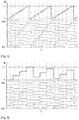
- T 10 discrete phase accumulation values are possible and coded from 0 to 9.
- the corresponding line of the above correspondence matrix indicates a logic level for each of the T logic signals constituting the signal numeric s ⁇ 9: 0>, ordered in columns from s ⁇ 9> to s ⁇ 0>.
- this logic level is binary, the logic signal being either at a first level denoted "0", or at a second level denoted "1".
- each multi-phase correspondence matrix comprises T rows representative of the T discrete possible phase accumulation values and T columns representative of the T logic signals. According to another convention, it could include T columns representative of T discrete possible phase accumulation values and T lines representative of T logic signals. Advantageously, it is symmetrical, so that this convention is completely irrelevant.
- each column of each multi-phase correspondence matrix each column indicating by convention the logic levels that must take one of the T logical signals resulting for the T discrete values of possible phase accumulation, presents circularly by modulo T only one transition from the first binary logic value to the second binary logic value for a first half of the T discrete values of possible phase accumulation and only one transition from the second binary logic value to the first binary logic value for a second half of the T possible discrete phase accumulation values.
- each column differs from that which precedes it or that which follows it only by a shift of a modulo T row of the values of coefficients which it contains, this shift remaining in the same direction from the first to the last column.
- the two digital signals received by the phase comparators 112 of the phase comparison block 110 have a frequency response very close to a straight line which starts from zero frequency and which decreases with frequency.
- the figure 5 illustrates, on a logarithmic frequency scale, the frequency response of one of the digital signals resulting from the accumulation of a phase ramp generated by a phase accumulator sampled by a clock signal of frequency F H equal to 1 MHz.
- the spectrum illustrated in this figure is thus parasitized by the frequency F H and its harmonics, a phenomenon well known to those skilled in the art.
- the equivalent sampling carried out by the phase accumulator does not generate spectrum aliasing or quantization noise because it is applied identically to each rising or falling edge of the clock.
- each phase comparator 112 is a linear operation in continuous time
- the spectrum of the result of this operation is a subtraction of the spectra of the two digital signals resulting from the phase accumulation values ( ⁇ ref and ⁇ c without adding additional noise.
- the figure 6 thus illustrates, according to a logarithmic frequency scale, the resulting spectrum at the output of the current summator 116 for the experimental values of the figure 5 .
- the lines of the frequency responses tend to compensate (here at -140 dB).
- the multiplicative factor ⁇ is greater than 1, the first parasitic peak is found at the frequency F ref , whereas in a conventional frequency synthesis device with integer division and frequency dividers, it would be at the frequency F ref / D.
- the phase accumulators 106 and 122 can easily be implemented with means for storing numbers encoded in binary form, in particular for positive integer values such as N and D. They must therefore just provide a sufficient number of bits for perform the arithmetic operations of accumulation of N and D in the set of T possible phase accumulation values. This number n must be greater than or equal to the number of bits necessary to represent, not only N and D, but also T.
- D can go up to 2 31 -1 (same for N), where a conventional integer division frequency synthesizer has values of D limited to 100 or 1000.
- the figure 8 schematically represents a PLL type frequency synthesis device 200, according to a second embodiment of the invention.
- the device 200 also differs from the device 100 in that the second phase accumulator 122 is no longer directly clocked at the output frequency F c , but at the reduced frequency F c / N d which nevertheless remains linked to F c .
- n ENT log 2 MAX NOT at - 1 , D - 1 + 2 .
- N a is less than N, the number of unnecessary implementation bits is reduced.
- the clock frequencies F ref and F c / N d of the two phase accumulators 106 and 122 also become close to each other, that of the second phase accumulator 122 being slowed down so as to further reduce consumption.
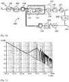
- the figure 9 schematically represents a PLL type frequency synthesis device 300, according to a third embodiment of the invention.
- This device 300 differs from device 200 in that each multi-phase converter 108 or 124 is preceded by a device for reducing dynamics by quantization. More precisely, this dynamic reduction is for example carried out using a Delta-Sigma modulation quantizer.
- a first Delta-Sigma modulation quantizer 302 is arranged between the first phase accumulator 106 and the first multi-phase converter 108.
- a second Delta-Sigma modulation quantizer 304 is arranged between the second phase accumulator 122. and the second multi-phase converter 124.
- the dynamic reduction allows a reduction in the number of bits taken into consideration in multi-phase converters, making the number of logic signals that they produce less and the phase comparison block 110 which receives them easier to produce. .
- the simplest solution consists in truncating the values to be converted on a number of bits n 'less than n by removing the least significant bits. .
- This truncation is mathematically equivalent to a new quantization of the digital data.
- This quantization produces an error which is generally assimilated to noise, called quantization noise.
- This noise has a fairly random spectrum but is often approached by a flat spectrum of white noise.
- the multi-phase converters then only need to convert n ′ bits into 2 n ′ logic signals at the cost of parasites which can be assimilated to additional noise in the output spectrum of the frequency synthesis device. Due to the frequency control, this noise is found mainly around the cut-off frequency of the device, its standard deviation decreasing when n 'increases.
- the advantage of using a Delta-Sigma modulation quantizer to achieve the dynamic reduction is to reduce this quantization noise, because the phase comparison block 110 is followed by a low-pass filter, in the This is the loop filter 118.
- the Delta-Sigma modulation function distorts the spectrum of the quantization noise by generating less low-frequency noise and more high-frequency noise close to F ref and F c / N d .
- This noise is then better filtered by the loop filter 118 if the frequencies F ref and F c / N d are sufficiently large compared to the cut-off frequency of the device.
- the order of the filter must be strictly greater than that of the Delta-Sigma modulation.
- the loop filter 118 is therefore at least of order 2, knowing that in addition it cannot be of too high order, that is to say that there remains advantageously d 'order less than or equal to 3.
- a first-order Delta-Sigma modulation quantizer is very simple to implement because it is always stable. It can consist of an adder followed by a register of n bits, the output of which is truncated by taking the n 'most significant bits while the (n - n') remaining low order bits are completed by 0s. in high order values to obtain new data on n input bits. The value of the new data thus created represents the fraction that was truncated at the output of the register. This value is added to the current input data on n bits and the result recorded in the register for the following cycle. This is how the Delta-Sigma modulation quantizer never erases the quantization error, but defers it in time.
- the first chronogram shows the evolution of the phase accumulation values ⁇ ref and ⁇ c whose ramps end up synchronizing before 3.10 -5 seconds.
- the second timing diagram shows the stabilization of the summed current ⁇ l at the output of the current summator 116 at the same time.
- the third timing diagram shows the convergence of the analog voltage V supplied by the loop filter 118 to the oscillator VCO 120 towards a stabilization value at the same time.
- the voltage V 0 is an internal voltage of the loop filter 118 which is indicated in the figure 14 .
- the figure 12 illustrates the same three chronograms in steady state of the frequency synthesis device 100, that is to say from 3.10 -5 seconds, on a finer time scale.
- the small remaining variations correspond to the residual interference of the clock frequencies F ref and F c after filtering by the loop filter 118.
- any of the devices described above can be integrated into any device requiring a synthesis of frequency, such as for example a radiofrequency receiver or transmitter, a timing clock for digital, analog or mixed circuits (ie analog and digital), a clocked measurement system, a time base, etc.
- the figure 13 illustrates an example of a filter of order 1 that can be chosen to produce the loop filter 118 of one or the other of the frequency synthesis devices of the figures 1 and 8 .
- This first-order filter receives at input the summed analog current ⁇ l from the phase comparison block 110 and supplies the analog control voltage V to the oscillator VCO 120 as an output. It also comprises a first capacitive circuit C 0 connecting the input to ground to perform an integration function by inserting a pole at zero frequency (PLL type II). It further comprises a second resistive and capacitive circuit R 1 , C 1 connecting the output to ground to create a phase margin by inserting a zero at low frequency.
- This first order filter cannot be used in the frequency synthesis device of the figure 9 since it cannot be of a strictly higher order than that of the Delta-Sigma quantifiers 302 and 304.
- the figure 14 illustrates an example of a filter of order 2 that can be chosen to produce the loop filter 118 of any one of the frequency synthesis devices of the figures 1 , 8 and 9 .
- This filter of order 2 differs from the filter of the figure 13 in that a third resistive circuit R 2 is interposed between the second circuit R 1 , C 1 and the output, and in that a fourth capacitive circuit C 2 connects the output to ground. These two additional circuits add a pole beyond the filter cutoff frequency.
- the figure 15 schematically represents the general architecture, in terms of logic gates, of an example of phase comparator 112 adapted for the frequency synthesis device of the figure 1 , 8 or 9 .
- This phase comparator comprises a first comparison input which receives one of the T first logic signals supplied by the first multi-phase converter 108.
- This signal is denoted s ref (i), with 0 ⁇ i ⁇ T, and its level logic is updated at frequency F ref .
- the comparator has a second comparison input which receives one of the T second logic signals supplied by the second multi-phase converter 124, more precisely that of the same index as s ref (i).
- This signal is denoted s c (i) and its logic level is updated at the frequency F c (or F c / N d ) -
- the first logic signal s ref (i) is received at the input of a NAND logic gate 400, the output of which is supplied at the input of a NAND logic gate 402 of a first RS flip-flop with two NAND logic gates. AND 402 and 404.
- the output of the NAND logic gate 402 supplies the "up" signal of the phase comparator 112 and is further returned to the input of the NAND logic gate 404.
- the output of the NAND logic gate AND 404 is supplied at the input of a NAND logic gate 406 of a second RS flip-flop with two NAND logic gates 406 and 408 and is further returned at the input of the NAND logic gate 402.
- the output of the logic NAND gate 406 is returned as the input of the logic NAND gate 408.
- the output of the logic NAND gate 408 is returned as the input of the logic NAND gate 406 and is further supplied as the input of the NAND logic gate 400. Finally, the first logic signal s ref (i) is also received at the input of the NAND logic gate 408.
- the second logic signal s c (i) is received at the input of a NAND logic gate 410, the output of which is supplied at the input of a NAND logic gate 412 of a third RS flip-flop with two NAND logic gates. AND 412 and 414.
- the output of the NAND logic gate 412 supplies the "down" signal of the phase comparator 112 and is further returned to the input of the NAND logic gate 414.
- the output of the NAND logic gate AND 414 is supplied at the input of a NAND logic gate 416 of a fourth RS flip-flop with two NAND logic gates 416 and 418 and is further returned at the input of the NAND logic gate 412.
- the output of the NAND logic gate 416 is returned to the input of the NAND logic gate 418.
- the output of the NAND logic gate 418 is returned to the input of the NAND logic gate 416 and is further supplied to the input of the NAND logic gate 410. Finally, the second logic signal s c (i) is also received at the input of the NAND logic gate 418.
- the “up” and “down” signals are further supplied at the input of a NAND logic gate 420, the output of which is provided at the inputs of the NAND logic gates 404 and 414 via a YES logic gate 422 (equivalent to a YES logic gate 422). double NO logic gate).
- the measured phase error is proportional to the width of the pulses generated on the “up” and “down” signals.
- the figure 17 schematically represents the general architecture of an example of charge pump 114 adapted for the frequency synthesis device of the figure 1 , 8 or 9 .
- This current generator I CP 504 supplies a first current mirror 506 with two n-MOS transistors which copies the current I CP on an output n-MOS transistor 508. It also supplies a second current mirror 510 with two p-MOS transistors, one of which, said output, is connected by its drain to the output of the OUI logic gate 500. The drain of the output n-MOS transistor 508 is connected to the output of the NOT logic gate 502. The output current I is taken between the transistor output n-MOS 508 and the output p-MOS transistor of the second current mirror 510.
- the current I CP is copied by the first current mirror 506 on the output n-MOS transistor 508 when it is activated, that is to say when the “down” signal is at level “1”. , and on the output p-MOS transistor of the second current mirror 510 when it is activated, that is to say when the “up” signal is at the “1” level.
- the currents of the output n-MOS and p-MOS transistors cancel each other out at output I.
- the figure 18 schematically represents the general architecture of an example of a phase accumulator 106 or 122 adapted for the frequency synthesis device of the figure 1 or 8 .
- This example is in particular adapted to a precise case according to which the values of phase increments N (or N a ) and D are coded on 4 bits and the registers In, Out occupy 4 bits of memory.
- the input register In stores the configuration value N (or N a ) for the phase accumulator 106 and the configuration value D for the phase accumulator 122.
- This architecture comprises a storage register 600 with four synchronous flip-flops clocked by the clock frequency F H (F ref for the phase accumulator 106 and F c for the phase accumulator 122).
- the four binary outputs of this register 600 supply the four bits Out ⁇ 0>, Out ⁇ 1>, Out ⁇ 2>, Out ⁇ 3> of the Out output register.
- the four binary inputs of this register 600 are supplied by a 4-bit adder 602 with four binary addition modules connected to each other in a conventional manner to carry out an addition on 4 bits.
- the four bits In ⁇ 0>, In ⁇ 1>, In ⁇ 2>, In ⁇ 3> of the input register In supply four respective inputs of the binary addition modules of the adder 602, which also receive the four outputs bits of the storage register 600 to perform the accumulation operation.
- the outputs of the four binary addition modules are supplied to the respective inputs of the four synchronous flip-flops of the storage register 600. Note that the modulo function of each phase accumulator 106, 122 is carried out implicitly by not using the carry-over of the l strong adder.
- each phase accumulator 106 or 122 is thus greatly simplified compared to that which must be considered in the patent document. US 9,509,320 B2 .
- the figure 19 schematically represents the general architecture of an example of phase accumulator 106 or 122 combined with a Delta-Sigma 302 or 304 quantizer, suitable for the frequency synthesis device of the figure 9 .
- This example is in particular suited to the precise case whereby the phase increment values N (or N a ) and D are coded on 4 bits and the register In occupies 4 bits of memory.
- the input register In stores the configuration value N (or N a ) for the phase accumulator 106 and the configuration value D for the phase accumulator 122.
- the phase accumulation function is performed by the storage register 600 and the 4-bit adder 602, arranged as previously in the example of figure 18 .
- the dynamic reduction function using a Delta-Sigma modulation quantizer is performed by an additional 4-bit adder 700 and by an additional storage register 702, these two modules being interposed between the storage register 600 and the output Out reduced to 2 bits.
- the additional adder 700 comprises four binary addition modules connected together in a conventional manner to perform an addition on 4 bits.
- the four output bits of the adder 602 feed four respective inputs of the binary additions modules of the additional adder 700, which also receive either 0's or outputs of the additional storage register 702 as a function of the desired dynamic reduction.
- the two binary addition modules relating to the two most significant bits receive 0s.
- the Out ⁇ 1> bit is determined by the output of the fourth synchronous flip-flop of the additional storage register 702.
- bit Out ⁇ 0> is determined by the output of the third synchronous flip-flop of the additional storage register 702.
- the figure 20 schematically represents the general architecture, in terms of logic gates, of an example of a multi-phase converter 108 or 124 adapted for the frequency synthesis device of the figure 1 , 8 or 9 .
- a NOR logic gate 800 receives the bits ⁇ ⁇ 0> and ⁇ ⁇ 1> to supply a logic value of an intermediate logic signal s A ⁇ 0>.
- a NOT logic gate 802 receives the bit ⁇ ⁇ 1> to provide a logic value of an intermediate logic signal s A ⁇ 1>.
- a logic NAND gate 804 receives the bits ⁇ ⁇ 0> and ⁇ ⁇ 1> to provide a logic value of an intermediate logic signal s A ⁇ 2>.
- a logical value of a signal intermediate logic s A ⁇ 3> is set to "1".
- a logic NOT gate 806 receives the bit ⁇ ⁇ 2>.
- NAND logic gates 808 respectively receive the four logic values of the four intermediate logic signals s A ⁇ 3: 0> and the output of the NAND logic gate 806 to provide respectively four logic values of four intermediate logic signals s B ⁇ 3: 0>.
- NOR logic gates 810 respectively receive the four logic values of the four intermediate logic signals s A ⁇ 3: 0> and the output of the NOT logic gate 806 to respectively provide four logic values of four intermediate logic signals s B ⁇ 7: 4>.
- eight NOR logic gates 812 respectively receive the eight logic values of the eight intermediate logic signals s B ⁇ 7: 0> and the bit ⁇ ⁇ 3> to respectively provide eight logic values of eight intermediate logic signals s C ⁇ 7: 0>.
- Eight NAND logic gates 814 respectively receive the eight logic values of the eight intermediate logic signals s B ⁇ 7: 0> and the bit ⁇ ⁇ 3> to respectively provide eight logic values of eight intermediate logic signals s C ⁇ 15: 8> .
- a logic NOT gate 816 receives the bit ⁇ ⁇ 4>.
- sixteen EXCLUSIVE-OR logic gates 818 respectively receive the sixteen logic values of the sixteen intermediate logic signals s C ⁇ 15: 0> and the bit ⁇ ⁇ 4> to provide respectively the sixteen logic values of the sixteen logic signals s ⁇ 15: 0>.
- Sixteen other EXCLUSIVE-OR logic gates 820 respectively receive the sixteen logic values of the sixteen intermediate logic signals s C ⁇ 15: 0> and the output of the NOT logic gate 816 to provide respectively the sixteen logic values of the sixteen logic signals s ⁇ 31: 16>.
- Oscillator 120 is for example a voltage-controlled oscillator formed of an inductor placed in parallel with two varactors arranged head-to-tail and two NMOS transistors whose gates are mounted head-to-tail so as to generate a gain sufficient to initiate then maintain the oscillation across the inductance, these transistors being polarized thanks to the current coming from the supply of the midpoint of the inductor.
Description
La présente invention concerne un dispositif de synthèse de fréquence à boucle de rétroaction.The present invention relates to a feedback loop frequency synthesis device.
On connaît de tels dispositifs, par exemple des boucles à phase asservie dites PLL (de l'Anglais « Phase Locked Loop »), généralement appelée boucles à verrouillage de phase.Such devices are known, for example phase locked loops known as PLL (from the English “Phase Locked Loop”), generally called phase locked loops.
Un dispositif de ce type comporte :
- une entrée destinée à recevoir un signal électrique oscillant à une fréquence de référence ;
- une sortie destinée à fournir un signal électrique oscillant à une fréquence de sortie ;
- un circuit d'asservissement de la fréquence de sortie à la fréquence de référence, reliant l'entrée à la sortie du dispositif et comportant un bloc de comparaison de phases, un filtre de boucle et un oscillateur à fréquence contrôlée fournissant le signal électrique oscillant à la fréquence de sortie, et
- une boucle de rétroaction reliant la sortie au bloc de comparaison de phases.
- an input for receiving an electrical signal oscillating at a reference frequency;
- an output for providing an electric signal oscillating at an output frequency;
- a circuit for slaving the output frequency to the reference frequency, connecting the input to the output of the device and comprising a phase comparison block, a loop filter and a frequency-controlled oscillator supplying the oscillating electric signal to the output frequency, and
- a feedback loop connecting the output to the phase comparison block.
L'oscillateur à fréquence contrôlée, par exemple de type VCO (de l'anglais « Voltage Controlled Oscillator »), DCO (de l'anglais « Digitally Controlled Oscillator ») ou autre, est commandé par une valeur numérique, une tension ou un courant analogique, voire une combinaison d'une valeur analogique et d'une valeur numérique. Bien que ce ne soit en général pas le cas, la fonction de transfert d'un tel oscillateur est souvent considérée comme linéaire et simplement représentée par un facteur de conversion K.The frequency-controlled oscillator, for example of the VCO (“Voltage Controlled Oscillator”), DCO (“Digitally Controlled Oscillator”) or other type, is controlled by a digital value, a voltage or a analog current, or even a combination of an analog value and a digital value. Although this is usually not the case, the transfer function of such an oscillator is often considered linear and simply represented by a conversion factor K.
Le bloc de comparaison de phases fonctionne en général sur des fronts de signaux à comparer, c'est-à-dire lorsque ces signaux atteignent une même valeur à même pente. La comparaison de phases fournit alors elle-même un ou plusieurs signaux qui représentent la différence de phase entre les fronts des signaux comparés. La plupart du temps, les signaux résultants de la comparaison sont transformés en un seul signal d'impulsion de courant ou de tension par une pompe de charge (de l'anglais « charge pump »). Ce courant (ou tension) est d'amplitude I (ou U) constante, il prend le signe de la différence de phase et son impulsion possède une largeur proportionnelle à la différence de phase. Le bloc de comparaison de phases peut être réalisé de façon plus ou moins analogique ou numérique.The phase comparison block generally operates on signal edges to be compared, that is to say when these signals reach the same value at the same slope. The phase comparison then itself provides one or more signals which represent the phase difference between the edges of the compared signals. Most of the time, the signals resulting from the comparison are transformed into a single current or voltage pulse signal by a charge pump. This current (or voltage) is of constant amplitude I (or U), it takes the sign of the phase difference and its pulse has a width proportional to the phase difference. The phase comparison block can be implemented more or less analog or digital.
L'impulsion fournie par la pompe de charge est ensuite filtrée par le filtre de boucle qui a pour base la réponse impulsionnelle d'un filtre intégrateur. Le filtre de boucle peut lui aussi être réalisé de façon plus ou moins analogique ou numérique.The impulse supplied by the charge pump is then filtered by the loop filter which is based on the impulse response of an integrating filter. The loop filter can also be produced in a more or less analog or digital fashion.
Le résultat issu du filtre de boucle est alors appliqué comme commande de l'oscillateur à fréquence contrôlée. Comme le filtre de boucle est intégrateur et que l'intégrale de la phase d'un signal périodique donne sa fréquence, la commande de l'oscillateur est bien proportionnelle à une fréquence qui va tendre vers la fréquence désirée en sortie au fur et à mesure que la différence de phase avec le signal de référence va tendre vers 0 ou vers une autre valeur constante.The result from the loop filter is then applied as a control of the frequency controlled oscillator. As the loop filter is integrating and the integral of the phase of a periodic signal gives its frequency, the control of the oscillator is indeed proportional to a frequency which will tend towards the desired frequency at the output as and when that the phase difference with the reference signal will tend towards 0 or towards another constant value.
Les PLL sont ainsi généralement utilisées dans les circuits électroniques en tant que sources de fréquences élevées. En effet, ces dispositifs permettent à partir d'une source à basse fréquence et de haute pureté spectrale (par exemple du quartz émettant des signaux périodiques à quelques MHz) d'obtenir des signaux périodiques à haute fréquence (par exemple quelques GHz) et avec une pureté spectrale de meilleure qualité que les dispositifs générant directement des signaux à haute fréquence.PLLs are thus generally used in electronic circuits as sources of high frequencies. Indeed, these devices allow from a low frequency source and high spectral purity (for example quartz emitting periodic signals at a few MHz) to obtain periodic signals at high frequency (for example a few GHz) and with spectral purity of better quality than devices directly generating high frequency signals.
Concrètement, pour une source de fréquence de référence basse et de haute pureté spectrale Fref, on obtient en sortie un signal de bonne pureté spectrale à haute fréquence Fc = α.Fref, a étant un facteur multiplicatif choisi supérieur à 1. Ce facteur multiplicatif α est généralement variable et de valeur réelle non entière afin de faire varier les différents canaux des normes utilisées suivant l'application.Concretely, for a source of low reference frequency and high spectral purity F ref , we obtain at output a signal of good spectral purity at high frequency F c = α.F ref , a being a multiplicative factor chosen greater than 1. This multiplying factor α is generally variable and of non-integer real value in order to vary the different channels of the standards used according to the application.
Un paramètre important des dispositifs de synthèse de fréquence est le temps Δt d'établissement de leur régime de fonctionnement, c'est-à-dire le temps qu'ils mettent à être fonctionnels, soit au démarrage, soit lors d'un changement de canal (i.e. changement du facteur a). Ce temps Δt perdure pendant un régime transitoire, généralement qualifié de phase d'accrochage, précédant le régime de fonctionnement. Ainsi par exemple, lors du passage ΔFc d'une fréquence Fc à une fréquence F'c, le régime transitoire de fréquence synthétisée suit une enveloppe exponentielle tendant asymptotiquement vers F'c à une fréquence de résonance propre ω pendant la durée Δt. La durée Δt de la phase d'accrochage dépend des paramètres constitutifs d'un dispositif de synthèse de fréquence et limite sa réactivité.An important parameter of frequency synthesis devices is the time Δt for establishing their operating regime, that is to say the time that they take to be operational, either at start-up or during a change of channel (ie change in factor a). This time Δt continues during a transient regime, generally referred to as a latching phase, preceding the operating regime. Thus for example, during the passage ΔF c from a frequency F c to a frequency F ' c , the transient regime of synthesized frequency follows an envelope exponential tending asymptotically towards F ' c at a natural resonant frequency ω for the duration Δt. The duration Δt of the latching phase depends on the constituent parameters of a frequency synthesis device and limits its reactivity.
Un autre paramètre important des dispositifs de synthèse de fréquence est la résolution des variations possibles du facteur multiplicatif α et donc la finesse de réglage possible de la fréquence de sortie Fc en fonction des applications ou normes visées.Another important parameter of frequency synthesis devices is the resolution of possible variations of the multiplying factor α and therefore the possible fineness of adjustment of the output frequency F c as a function of the targeted applications or standards.
D'autres paramètres à considérer, pour optimiser les dispositifs de synthèse de fréquence et la qualité des signaux périodiques de fréquence Fc obtenus en sortie, incluent le bruit de phase, la gigue (de l'anglais « jitter »), les signaux parasites (de l'anglais « spurious signais ») et la consommation électrique.Other parameters to be considered, in order to optimize the frequency synthesis devices and the quality of the periodic signals of frequency F c obtained at the output, include phase noise, jitter, parasitic signals. (from the English "spurious signais") and power consumption.
Selon une conception bien connue des PLL, dite à division entière, le facteur multiplicatif α est choisi comme le quotient de deux valeurs entières N et D où la valeur N est généralement supérieure à D. Pour parvenir à cet asservissement Fc = α.Fref = N/D.Fref, un diviseur de fréquence de facteur D est disposé dans le circuit d'asservissement entre l'entrée et une première entrée de comparaison d'un comparateur du bloc de comparaison de phases, tandis qu'un diviseur de fréquence de facteur N est disposé dans la boucle de rétroaction entre la sortie, qui correspond à la sortie de l'oscillateur à fréquence contrôlée, et une deuxième entrée de comparaison du comparateur de phases. De la sorte, la fréquence des deux signaux comparés par le comparateur de phases est destinée à converger vers Fref/D = Fc/N lorsque la boucle est verrouillée. Ainsi, en sortie du comparateur de phases, bien que filtrée par le filtre de boucle, cette fréquence Fref/D se retrouve au niveau de la commande de l'oscillateur à fréquence contrôlée et donc en tant que parasite dans le spectre du signal de sortie. Par ailleurs, il est clair que la valeur de D est directement corrélée à la résolution des variations possibles du facteur multiplicatif α puisque ces variations se font, pour différentes valeurs de N possibles, par pas fréquentiels de Fref/D.According to a well-known concept of PLLs, called integer division, the multiplicative factor α is chosen as the quotient of two integer values N and D where the value N is generally greater than D. To achieve this slaving F c = α.F ref = N / DF ref , a frequency divider of factor D is arranged in the servo circuit between the input and a first comparison input of a comparator of the phase comparison block, while a frequency divider factor N is disposed in the feedback loop between the output, which corresponds to the output of the frequency controlled oscillator, and a second comparison input of the phase comparator. In this way, the frequency of the two signals compared by the phase comparator is intended to converge towards F ref / D = F c / N when the loop is locked. Thus, at the output of the phase comparator, although filtered by the loop filter, this frequency F ref / D is found at the level of the control of the frequency-controlled oscillator and therefore as a parasite in the spectrum of the signal of exit. Moreover, it is clear that the value of D is directly correlated with the resolution of the possible variations of the multiplicative factor α since these variations occur, for different possible values of N, by frequency steps of F ref / D.
Il en résulte que pour augmenter la résolution des variations possibles du facteur multiplicatif a, il conviendrait d'augmenter la valeur de D. Mais dans ce cas, la fréquence Fref/D serait réduite et il conviendrait alors de réduire également la bande passante du filtre de boucle pour limiter les parasites résultants dans le spectre du signal de sortie. Or limiter la bande passante du filtre de boucle conduit à allonger le temps Δt d'établissement du régime de fonctionnement. Par conséquent, optimiser conjointement les deux paramètres importants d'une PLL, que constituent le temps d'établissement du régime de fonctionnement et la résolution des variations possibles du facteur multiplicatif a, est impossible à réaliser avec une PLL à division entière.It follows that in order to increase the resolution of the possible variations of the multiplying factor a, it would be advisable to increase the value of D. But in this case, the frequency F ref / D would be reduced and it would then be advisable also to reduce the bandwidth of the loop filter to limit the resulting noise in the spectrum of the output signal. However, limiting the passband of the loop filter leads to lengthening the time Δt for establishing the operating regime. Therefore, optimize together the two important parameters of a PLL, which constitute the settling time of the operating regime and the resolution of possible variations of the multiplying factor α, is impossible to achieve with an integer division PLL.
Par ailleurs, les contributions au bruit de phase induit en sortie dépendent directement elles aussi de la fréquence de coupure de la PLL. Dans la bande passante, le bruit est dominé par la contribution du signal de référence. Bien que multiplié par a, il reste en général moindre que celui apporté par la PLL elle-même. Il peut ainsi être préférable de monter la fréquence de coupure de la PLL afin d'abaisser le bruit de phase dans la partie basse du spectre obtenu en sortie. Mais dans ce cas, c'est au détriment de la valeur de D. Par conséquent, optimiser conjointement le bruit de phase et la résolution des variations possibles du facteur multiplicatif a, est impossible à réaliser avec une PLL à division entière.Moreover, the contributions to the phase noise induced at the output also depend directly on the cut-off frequency of the PLL. In the passband, the noise is dominated by the contribution of the reference signal. Although multiplied by a, it is generally less than that provided by the PLL itself. It may thus be preferable to increase the cut-off frequency of the PLL in order to lower the phase noise in the lower part of the spectrum obtained at the output. But in this case, it is to the detriment of the value of D. Therefore, jointly optimizing the phase noise and the resolution of possible variations of the multiplying factor a, is impossible to achieve with an integer-division PLL.
Une solution partielle à ces inconvénients consiste à concevoir une PLL à pas fractionnaires comme enseigné dans la demande de brevet
Cependant, pour réaliser cette commutation du diviseur de la boucle de rétroaction entre les deux valeurs N et N+1 selon une proportion souhaitée, un modulateur Delta-Sigma est généralement utilisé. Ce modulateur a la particularité de générer un signal résultant d'une quantification du coefficient β sur 1 bit et la quantification produit nécessairement une erreur de quantification qui, dans le cas du modulateur Delta-Sigma, n'est pas répartie uniformément dans le spectre de sortie mais est amplifiée dans les hautes fréquences. Le filtre de boucle atténue donc partiellement le bruit résultant de cette erreur. Néanmoins, une PLL à pas fractionnaires produit un signal qui reste plus ou moins entaché d'un bruit supplémentaire dû à la génération du coefficient β. D'ailleurs plus β aura besoin de précision (i.e. pour une meilleure résolution à N et D constants), plus ce bruit supplémentaire sera important.However, to achieve this switching of the divider of the feedback loop between the two values N and N + 1 according to a desired proportion, a Delta-Sigma modulator is generally used. This modulator has the particularity of generating a signal resulting from a quantization of the coefficient β on 1 bit and the quantization necessarily produces a quantization error which, in the case of the Delta-Sigma modulator, is not distributed uniformly in the spectrum of output but is amplified in the high frequencies. The loop filter therefore partially attenuates the noise resulting from this error. Nevertheless, a fractional step PLL produces a signal which remains more or less marred by additional noise due to the generation of the coefficient β. Moreover, the more precision β will need (i.e. for a better resolution at constant N and D), the more this additional noise will be important.
De plus, une PLL à pas fractionnaire n'optimise pas non plus le bruit de phase indépendamment du facteur multiplicatif a, la fréquence de fonctionnement du comparateur de phases restant dépendante de ce facteur.In addition, a fractional pitch PLL does not optimize phase noise independently of the multiplying factor α either, the operating frequency of the phase comparator remaining dependent on this factor.
Une autre solution consiste à ne pas utiliser de diviseurs de fréquences mais des accumulateurs de phases, comme enseigné par exemple dans les demandes de brevets
Conformément à cette autre solution, l'invention concerne plus précisément un dispositif de synthèse de fréquence à boucle de rétroaction comportant :
- une entrée destinée à recevoir un signal électrique oscillant à une fréquence de référence ;
- une sortie destinée à fournir un signal électrique oscillant à une fréquence de sortie ;
- un circuit d'asservissement de la fréquence de sortie à la fréquence de référence, reliant l'entrée à la sortie du dispositif et comportant un premier accumulateur de phase cadencé à une fréquence liée à la fréquence de référence, un bloc de comparaison de phases, un filtre de boucle et un oscillateur à fréquence contrôlée fournissant le signal électrique oscillant à la fréquence de sortie ; et
- une boucle de rétroaction reliant la sortie au bloc de comparaison de phases, comportant un deuxième accumulateur de phase cadencé à une fréquence liée à la fréquence de sortie, les premier et deuxième accumulateurs de phase étant aptes à fournir un même nombre T de valeurs discrètes d'accumulation de phase possibles.
- an input for receiving an electrical signal oscillating at a reference frequency;
- an output for providing an electric signal oscillating at an output frequency;
- a circuit for slaving the output frequency to the reference frequency, connecting the input to the output of the device and comprising a first phase accumulator clocked at a frequency related to the reference frequency, a phase comparison block, a loop filter and a frequency controlled oscillator providing the electric signal oscillating at the output frequency; and
- a feedback loop connecting the output to the phase comparison block, comprising a second phase accumulator clocked at a frequency related to the output frequency, the first and second phase accumulators being able to provide the same number T of discrete values d phase accumulation possible.
Ainsi, pour une PLL à division entière de facteur multiplicatif α = N/D, le premier accumulateur de phase peut par exemple être associé à une valeur d'incrément de phase égale à N et le deuxième à une valeur d'incrément de phase égale à D.Thus, for an integer-division PLL with a multiplying factor α = N / D, the first phase accumulator can for example be associated with a phase increment value equal to N and the second with a phase increment value equal to D.
Il résulte de cette autre solution que la fréquence de fonctionnement du comparateur de phases peut être rendue indépendante du facteur α et donc du choix de D. D peut alors être augmenté dans des proportions bien plus importantes que celles des dispositifs à diviseurs de fréquences, tout en conservant une fréquence de fonctionnement élevée du comparateur de phases, d'où une meilleure résolution sans concession sur le temps Δt d'établissement du régime de fonctionnement ou sur le bruit de phase.It follows from this other solution that the operating frequency of the phase comparator can be made independent of the factor α and therefore of the choice of D. D can then be increased in much greater proportions than those of frequency divider devices, while maintaining a high operating frequency of the phase comparator, hence better resolution without concession on the time Δt d ' establishment of the operating mode or on the phase noise.
Cependant cette autre solution fournit des valeurs numériques en sorties des accumulateurs de phases et celles-ci sont cadencées selon des fréquences différentes. Plus précisément, dans les documents
Ce problème est par exemple résolu de façon partielle et non satisfaisante dans
Ce problème est en revanche résolu de façon plus satisfaisante dans le document de brevet
Néanmoins, les accumulateurs de phases ne peuvent pas produire des valeurs s'incrémentant indéfiniment. Il est généralement nécessaire de prévoir une valeur seuil de phase accumulée au-delà de laquelle il est prévu de soustraire une valeur de modulo. Mais il est alors également nécessaire de prévoir un mécanisme de synchronisation des soustractions de la valeur de modulo entre les accumulateurs de phases, ce qui présente une certaine complexité et est susceptible d'engendrer un bruit parasite transitoire perceptible en sortie de l'oscillateur.However, phase accumulators cannot produce values that increment indefinitely. It is generally necessary to provide an accumulated phase threshold value beyond which it is intended to subtract a modulo value. However, it is then also necessary to provide a mechanism for synchronizing the subtractions of the modulo value between the phase accumulators, which presents a certain complexity and is liable to generate a transient parasitic noise perceptible at the output of the oscillator.
Il peut ainsi être souhaité de prévoir un dispositif de synthèse de fréquence à boucle de rétroaction qui permette de s'affranchir d'au moins une partie des problèmes et contraintes précités.It may thus be desirable to provide a feedback loop frequency synthesis device which makes it possible to overcome at least some of the aforementioned problems and constraints.
Il est donc proposé un dispositif de synthèse de fréquence à boucle de rétroaction comportant :
- une entrée destinée à recevoir un signal électrique oscillant à une fréquence de référence ;
- une sortie destinée à fournir un signal électrique oscillant à une fréquence de sortie ;
- un circuit d'asservissement de la fréquence de sortie à la fréquence de référence, reliant l'entrée à la sortie du dispositif et comportant un premier accumulateur de phase cadencé à une fréquence liée à la fréquence de référence, un bloc de comparaison de phases, un filtre de boucle et un oscillateur à fréquence contrôlée fournissant le signal électrique oscillant à la fréquence de sortie ; et
- une boucle de rétroaction reliant la sortie au bloc de comparaison de phases, comportant un deuxième accumulateur de phase cadencé à une fréquence liée à la fréquence de sortie, les premier et deuxième accumulateurs de phase étant aptes à fournir un même nombre T de valeurs discrètes d'accumulation de phase possibles ;
- le circuit d'asservissement est configuré pour fournir, au bloc de comparaison de phases, T premiers signaux logiques distincts dont les niveaux logiques dépendent continûment des valeurs d'accumulation de phase fournies par le premier accumulateur de phase selon une première matrice de correspondance multi-phases entre les T valeurs discrètes d'accumulation de phase possibles et les T premiers signaux ;
- la boucle de rétroaction est configurée pour fournir, au bloc de comparaison de phases, T deuxièmes signaux logiques distincts dont les niveaux logiques dépendent continûment des valeurs d'accumulation de phase fournies par le deuxième accumulateur de phase selon une deuxième matrice de correspondance multi-phases entre les T valeurs discrètes d'accumulation de phase possibles et les T deuxièmes signaux ; et
- le bloc de comparaison de phases comporte T comparateurs de phases à portes logiques recevant respectivement en temps continu les T premiers signaux logiques sur T premières entrées de comparaison et les T deuxièmes signaux logiques sur T deuxièmes entrées de comparaison.
- an input for receiving an electrical signal oscillating at a reference frequency;
- an output for providing an electric signal oscillating at an output frequency;
- a circuit for slaving the output frequency to the reference frequency, connecting the input to the output of the device and comprising a first phase accumulator clocked at a frequency related to the reference frequency, a phase comparison block, a loop filter and a frequency controlled oscillator providing the electric signal oscillating at the output frequency; and
- a feedback loop connecting the output to the phase comparison block, comprising a second phase accumulator clocked at a frequency related to the output frequency, the first and second phase accumulators being able to provide the same number T of discrete values d possible phase accumulation;
- the servo circuit is configured to supply, to the phase comparison block, T first distinct logic signals, the logic levels of which depend continuously on the phase accumulation values supplied by the first phase accumulator according to a first multi-correspondence matrix. phases between the T discrete possible phase accumulation values and the T first signals;
- the feedback loop is configured to supply, to the phase comparison block, T second distinct logic signals whose logic levels depend continuously on the phase accumulation values supplied by the second phase accumulator according to a second multi-phase correspondence matrix between the T discrete possible phase accumulation values and the T second signals; and
- the phase comparison block comprises T phase comparators with logic gates receiving respectively in continuous time the first T logic signals on T first comparison inputs and the T second logic signals on T second comparison inputs.
Ainsi, il n'est plus nécessaire de gérer la soustraction d'une valeur de modulo puisque cela peut se faire implicitement et automatiquement par la prise en compte des T valeurs discrètes d'accumulation de phase possibles dans chaque matrice de correspondance multi-phases avec les T premiers ou T deuxièmes signaux logiques. En effet, chaque saut de phase correspond à un saut équivalent dans les lignes ou colonnes de la matrice, avec retour en début de lignes ou colonnes dès que la valeur maximale ou modulo T est atteinte, et le nombre de signaux logiques est égal à cette valeur de modulo. Il n'est donc a fortiori plus nécessaire de gérer de synchronisation de soustraction de valeur de modulo entre signaux à comparer.Thus, it is no longer necessary to manage the subtraction of a modulo value since this can be done implicitly and automatically by taking into account the T discrete phase accumulation values possible in each multi-phase correspondence matrix with the first T or T second logic signals. In fact, each phase jump corresponds to an equivalent jump in the rows or columns of the matrix, with a return to the start of rows or columns as soon as the maximum value or modulo T is reached, and the number of logic signals is equal to this modulo value. It is therefore a fortiori no longer necessary to manage modulo value subtraction synchronization between signals to be compared.
Par ailleurs, le fait de produire 2T signaux logiques dépendant continument des valeurs d'accumulation de phase fournies par les accumulateurs de phase et de les comparer entre eux à l'aide de portes logiques permet de se passer d'une conversion numérique/analogique spécifique. De plus, on constate en pratique que la résolution en fréquence ne dépend pas du nombre T de comparateurs de phases dans le bloc de comparaison.Moreover, the fact of producing 2T logic signals depending continuously on the phase accumulation values supplied by the phase accumulators and of comparing them with each other using logic gates makes it possible to dispense with a specific digital / analog conversion. . In addition, it is observed in practice that the frequency resolution does not depend on the number T of phase comparators in the comparison block.
Il en résulte des performances de haute résolution au moins aussi satisfaisantes que dans le document de brevet
De façon optionnelle :
- le circuit d'asservissement comporte un premier convertisseur multi-phases entre le premier accumulateur de phase et le bloc de comparaison de phases, configuré pour implémenter la première matrice de correspondance multi-phases ; et
- la boucle de rétroaction comporte un deuxième convertisseur multi-phases entre le deuxième accumulateur de phase et le bloc de comparaison de phases, configuré pour implémenter la deuxième matrice de correspondance multi-phases.
- the servo circuit comprises a first multi-phase converter between the first phase accumulator and the phase comparison block, configured to implement the first multi-phase correspondence matrix; and
- the feedback loop includes a second multi-phase converter between the second phase accumulator and the phase comparison block, configured to implement the second multi-phase correspondence matrix.
De façon optionnelle également, chacun des premier et deuxième convertisseurs multi-phases implémente sa matrice de correspondance multi-phases sous la forme d'un ensemble de portes logiques recevant en entrée une valeur courante d'accumulation de phase codée en binaire sur ln(T)/ln(2) bits, où ln(.) est la fonction logarithme népérien, et fournissant en sortie T valeurs courantes de niveaux logiques.Also optionally, each of the first and second multi-phase converters implements its multi-phase correspondence matrix in the form of a set of logic gates receiving a value as input. phase accumulation current coded in binary on ln (T) / ln (2) bits, where ln (.) is the natural logarithm function, and providing T current values of logic levels as output.
De façon optionnelle également, chaque coefficient de chacune des première et deuxième matrices de correspondance multi-phases est soit à une première valeur binaire indicatrice d'un premier niveau logique de signal logique, soit à une deuxième valeur binaire indicatrice d'un deuxième niveau logique de signal logique.Also optionally, each coefficient of each of the first and second multi-phase correspondence matrices is either at a first binary value indicative of a first logic level of logic signal, or at a second binary value indicative of a second logic level logic signal.
De façon optionnelle également, chaque ligne ou colonne de chacune des première et deuxième matrices de correspondance multi-phases, lorsque cette ligne ou colonne indique les niveaux logiques que doit prendre l'un des T premiers ou deuxièmes signaux logiques pour les T valeurs discrètes d'accumulation de phase possibles, ne présente circulairement par modulo T qu'une seule transition de la première valeur binaire vers la deuxième valeur binaire pour une première moitié des T valeurs discrètes d'accumulation de phase possibles et qu'une seule transition de la deuxième valeur binaire vers la première valeur binaire pour une deuxième moitié des T valeurs discrètes d'accumulation de phase possibles.Also optionally, each row or column of each of the first and second multi-phase correspondence matrices, when this row or column indicates the logic levels that one of the T first or second logic signals must take for the T discrete values d 'possible phase accumulation, presents circularly by modulo T only one transition from the first binary value to the second binary value for a first half of the T possible discrete phase accumulation values and only one transition from the second binary value to the first binary value for a second half of the T possible discrete phase accumulation values.
De façon optionnelle également, chaque ligne ou colonne de chacune des première et deuxième matrices de correspondance multi-phases, lorsque cette ligne ou colonne indique les niveaux logiques que doit prendre l'un des T premiers ou deuxièmes signaux logiques pour les T valeurs discrètes d'accumulation de phase possibles, ne diffère de celle qui la précède ou de celle qui la suit que par un décalage d'une colonne ou respectivement d'une ligne modulo T des valeurs de coefficients qu'elle contient, ce décalage restant dans le même sens de la première à la dernière ligne ou colonne.Also optionally, each row or column of each of the first and second multi-phase correspondence matrices, when this row or column indicates the logic levels that one of the T first or second logic signals must take for the T discrete values d The possible phase accumulation differs from that which precedes it or that which follows it only by a shift of one column or respectively of a modulo T row of the values of coefficients that it contains, this shift remaining in the same meaning from the first to the last row or column.
De façon optionnelle également, chacune des première et deuxième matrices de correspondance est symétrique.Also optionally, each of the first and second correspondence matrices is symmetrical.
De façon optionnelle également, les première et deuxième matrices de correspondance sont identiques.Also optionally, the first and second correspondence matrices are identical.
De façon optionnelle également, le bloc de comparaison de phases comporte T pompes de charge recevant respectivement en temps continu T paires de signaux impulsionnels fournies par les T comparateurs de phases et fournissant respectivement en temps continu T courants de sortie.Also optionally, the phase comparison unit comprises T charge pumps receiving respectively in continuous time T pairs of pulse signals supplied by the T phase comparators and respectively supplying T output currents in continuous time.
De façon optionnelle également, le bloc de comparaison de phases comporte un sommateur de courants recevant en parallèle les T courants de sortie fournis par les T pompes de charge pour fournir un unique courant sommé en sortie du bloc de comparaison de phases.Also optionally, the phase comparison block comprises a current summator receiving in parallel the T output currents supplied by the T charge pumps to supply a single summed current at the output of the phase comparison block.
L'invention sera mieux comprise à l'aide de la description qui va suivre, donnée uniquement à titre d'exemple et faite en se référant aux dessins annexés dans lesquels :
- [
Fig.1 ] lafigure 1 représente schématiquement la structure générale d'un dispositif de synthèse de fréquence à boucle de rétroaction, selon un premier mode de réalisation de l'invention, - [
Fig.2 ] lafigure 2 est un chronogramme illustrant les évolutions de valeurs d'accumulation de phase obtenues à l'aide du dispositif de lafigure 1 , - [
Fig.3 ] lafigure 3 est un chronogramme illustrant les évolutions de T premiers ou deuxièmes signaux logiques fournis par le dispositif de lafigure 1 , en dépendance de valeurs d'accumulation de phase obtenues par sauts unitaires, - [
Fig.4 ] lafigure 4 est un chronogramme illustrant les évolutions de T premiers ou deuxièmes signaux logiques fournis par le dispositif de lafigure 1 , en dépendance de valeurs d'accumulation de phase obtenues par sauts de trois unités, - [
Fig.5 ] lafigure 5 est un spectre à échelle logarithmique de fréquences illustrant les caractéristiques d'un signal obtenu à l'aide du dispositif de lafigure 1 , - [
Fig.6 ] lafigure 6 est un spectre à échelle logarithmique de fréquences illustrant les caractéristiques d'un autre signal obtenu à l'aide du dispositif de lafigure 1 , - [
Fig.7 ] lafigure 7 est un diagramme indiquant une évolution de résolution en fréquence du dispositif de lafigure 1 en fonction d'un nombre n de bits codant T valeurs d'accumulation de phases possibles, - [
Fig.8 ] lafigure 8 représente schématiquement la structure générale d'un dispositif de synthèse de fréquence à boucle de rétroaction, selon un deuxième mode de réalisation de l'invention, - [
Fig.9 ] lafigure 9 représente schématiquement la structure générale d'un dispositif de synthèse de fréquence à boucle de rétroaction, selon un troisième mode de réalisation de l'invention, - [
Fig.10 ] lafigure 10 est un spectre à échelle logarithmique de fréquences illustrant les caractéristiques d'un signal obtenu à l'aide du dispositif de lafigure 9 , - [
Fig.11 ] lafigure 11 est un ensemble de trois chronogrammes illustrant les évolutions de différentes grandeurs du dispositif de lafigure 1 en régime transitoire de démarrage, - [
Fig.12 ] lafigure 12 est un ensemble de trois chronogrammes illustrant les évolutions de différentes grandeurs du dispositif de lafigure 1 en régime établi de fonctionnement, - [
Fig.13 ] lafigure 13 représente un exemple de filtre de boucle pour l'un ou l'autre des dispositifs desfigures 1 et 8 , - [
Fig.14 ] lafigure 14 représente un autre exemple de filtre de boucle pour l'un quelconque des dispositifs desfigures 1 ,8 et 9 , - [
Fig.15 ] lafigure 15 représente schématiquement l'architecture d'un exemple de comparateur de phases pour l'un quelconque des dispositifs de synthèse de fréquence desfigures 1 ,8 et 9 , - [
Fig.16 ] lafigure 16 est un ensemble de quatre chronogrammes illustrant les évolutions des signaux logiques en entrée et en sortie du comparateur de phase de lafigure 15 , - [
Fig.17 ] lafigure 17 représente schématiquement l'architecture d'un exemple de pompe de charge pour l'un quelconque des dispositifs de synthèse de fréquence desfigures 1 ,8 et 9 , - [
Fig.18 ] lafigure 18 représente schématiquement l'architecture d'un exemple d'accumulateur de phase adapté pour le dispositif de synthèse de fréquence de lafigure 1 ou 8 , - [
Fig.19 ] lafigure 19 représente schématiquement l'architecture d'un exemple d'accumulateur de phase à réduction de dynamique par modulation Delta-Sigma adapté pour le dispositif de synthèse de fréquence de lafigure 9 , et - [
Fig.20 ] lafigure 20 représente schématiquement l'architecture d'un exemple de convertisseur multi-phases pour l'un quelconque des dispositifs de synthèse de fréquence desfigures 1 ,8 et 9 .
- [
Fig. 1 ] thefigure 1 schematically represents the general structure of a feedback loop frequency synthesis device, according to a first embodiment of the invention, - [
Fig. 2 ] thefigure 2 is a chronogram illustrating the evolution of phase accumulation values obtained using the device of thefigure 1 , - [
Fig. 3 ] thefigure 3 is a chronogram illustrating the evolutions of T first or second logic signals supplied by the device of thefigure 1 , depending on phase accumulation values obtained by unit jumps, - [
Fig. 4 ] thefigure 4 is a chronogram illustrating the evolutions of T first or second logic signals supplied by the device of thefigure 1 , depending on phase accumulation values obtained by jumps of three units, - [
Fig. 5 ] thefigure 5 is a spectrum on a logarithmic scale of frequencies illustrating the characteristics of a signal obtained using the device of thefigure 1 , - [
Fig. 6 ] thefigure 6 is a logarithmic scale spectrum of frequencies illustrating the characteristics of another signal obtained using the device of thefigure 1 , - [
Fig. 7 ] thefigure 7 is a diagram indicating an evolution of the frequency resolution of the device of thefigure 1 as a function of a number n of bits encoding T possible phase accumulation values, - [
Fig. 8 ] thefigure 8 schematically represents the general structure of a feedback loop frequency synthesis device, according to a second embodiment of the invention, - [
Fig. 9 ] thefigure 9 schematically represents the general structure of a feedback loop frequency synthesis device, according to a third embodiment of the invention, - [
Fig. 10 ] thefigure 10 is a spectrum on a logarithmic scale of frequencies illustrating the characteristics of a signal obtained using the device of thefigure 9 , - [
Fig.11 ] thefigure 11 is a set of three chronograms illustrating the evolutions of different sizes of the device of thefigure 1 in transient starting regime, - [
Fig. 12 ] thefigure 12 is a set of three chronograms illustrating the evolutions of different sizes of the device of thefigure 1 in steady state of operation, - [
Fig. 13 ] thefigure 13 shows an example of a loop filter for one or other of the devices of thefigures 1 and8 , - [
Fig. 14 ] thefigure 14 shows another example of a loop filter for any of the devices in thefigures 1 ,8 and9 , - [
Fig. 15 ] thefigure 15 schematically represents the architecture of an example of a phase comparator for any one of the frequency synthesis devices of thefigures 1 ,8 and9 , - [
Fig. 16 ] thefigure 16 is a set of four chronograms illustrating the changes in the logic signals at the input and output of the phase comparator of thefigure 15 , - [
Fig. 17 ] thefigure 17 schematically represents the architecture of an example of a charge pump for any one of the frequency synthesis devices of thefigures 1 ,8 and9 , - [
Fig. 18 ] thefigure 18 schematically represents the architecture of an example of a phase accumulator suitable for the frequency synthesis device of thefigure 1 or8 , - [
Fig.19 ] thefigure 19 schematically represents the architecture of an example of a phase accumulator with dynamic reduction by Delta-Sigma modulation adapted for the frequency synthesis device of thefigure 9 , and - [
Fig. 20 ] thefigure 20 schematically represents the architecture of an example of a multi-phase converter for any one of the frequency synthesis devices offigures 1 ,8 and9 .
La
Il comporte en outre un circuit 102 d'asservissement de la fréquence de sortie Fc à la fréquence de référence Fref et une boucle de rétroaction 104 pour la fourniture d'informations issues du signal périodique de sortie au circuit d'asservissement 102.It further comprises a
Plus précisément, le circuit d'asservissement 102 relie l'entrée à la sortie du dispositif 100 et comporte :
- un premier accumulateur de
phase 106 cadencé à une fréquence liée à la fréquence de référence Fref : dans l'exemple de lafigure 1 , la cadence est directement celle de la fréquence Fref et l'accumulateur dephase 106 présente une valeur entière d'incrément de phase notée N dans un ensemble ordonné de T valeurs discrètes d'accumulation de phase possibles ; - un premier convertisseur multi-phases 108 disposé en sortie du premier accumulateur de
phase 106, recevant une valeur codée de phase accumulée ϕref fournie par le premier accumulateur dephase 106 et fournissant T premiers signaux logiques dont les niveaux logiques dépendent en temps continu de cette valeur de phase ϕref selon une première matrice de correspondance multi-phases entre les T valeurs discrètes d'accumulation de phase possibles et les T premiers signaux : selon une implémentation simple et préférée, T est une puissance de 2, T = 2n, et la valeur de phase accumulée ϕref fournie par le premier accumulateur dephase 106 est codée de 1 à T sur n bits comme illustré sur lafigure 1 ; - un bloc de comparaison de
phases 110 comportant : T comparateurs de phases 112 à portes logiques recevant respectivement en temps continu les T premiers signaux logiques sur T premières entrées de comparaison et fournissant respectivement en temps continu T paires de signaux « up » et « down » ; T pompes de charge 114 recevant respectivement en temps continu les T paires de signaux « up » et « down » fournies par les T comparateurs de phases 112 et fournissant respectivement en temps continu T courants de sortie ; et un sommateur de courants 116 recevant en parallèle les T courants de sortie fournis par les T pompes de charge 114 pour fournir un unique courant sommé en sortie du bloc de comparaison de phases 110 ; - un filtre de boucle 118 disposé en sortie du bloc de comparaison de phases 110 pour recevoir le courant sommé : dans l'exemple de la
figure 1 , il s'agit d'un filtre analogique ; et - un oscillateur à fréquence contrôlée 120 disposé en sortie du filtre de boucle 118 et fournissant le signal périodique oscillant à la fréquence de sortie : dans l'exemple de la
figure 1 , l'oscillateur 120 est de type VCO, c'est-à-dire commandé en tension analogique fournie par le filtre de boucle 118.
- a
first phase accumulator 106 clocked at a frequency linked to the reference frequency F ref : in the example offigure 1 , the rate is directly that of the frequency F ref and thephase accumulator 106 has an integer phase increment value denoted N in an ordered set of T possible discrete phase accumulation values; - a first
multi-phase converter 108 disposed at the output of thefirst phase accumulator 106, receiving an accumulated phase coded value ϕ ref supplied by thefirst phase accumulator 106 and supplying T first logic signals whose logic levels depend in continuous time on this phase value ϕ ref according to a first multi-phase correspondence matrix between the T discrete possible phase accumulation values and the first T signals: according to a simple and preferred implementation, T is a power of 2, T = 2 n , and the accumulated phase value ϕ ref supplied by thefirst phase accumulator 106 is coded from 1 to T over n bits as illustrated in the figurefigure 1 ; - a phase comparison block 110 comprising:
T phase comparators 112 with logic gates receiving respectively in continuous time the T first logic signals on T first comparison inputs and supplying respectively in continuous time T pairs of “up” and “down” signals ; T charge pumps 114 receiving respectively in continuous time the T pairs of “up” and “down” signals supplied by theT phase comparators 112 and respectively supplying T output currents in continuous time; and acurrent summator 116 receiving in parallel the T output currents supplied by the T charge pumps 114 to provide a single summed current at the output of thephase comparison block 110; - a
loop filter 118 arranged at the output of thephase comparison block 110 to receive the summed current: in the example offigure 1 , it is an analog filter; and - a controlled
frequency oscillator 120 placed at the output of theloop filter 118 and supplying the periodic signal oscillating at the output frequency: in the example offigure 1 , theoscillator 120 is of the VCO type, that is to say controlled by analog voltage supplied by theloop filter 118.
Plus précisément également, la boucle de rétroaction 104 récupère le signal périodique fourni par l'oscillateur 120 pour le fournir en entrée d'un deuxième accumulateur de phase 122 cadencé à une fréquence liée à la fréquence de sortie Fc : dans l'exemple de la
Les T deuxièmes signaux logiques fournis en sortie du deuxième convertisseur multi-phases 124 sont respectivement reçus sur T deuxièmes entrées de comparaison des comparateurs de phases 112.The T second logic signals supplied at the output of the second
Dans l'exemple non limitatif de la
En pratique, on notera aussi que le sommateur de courants 116 peut être implémenté sous la simple forme d'un raccordement électrique des T sorties de pompes de charge 114.In practice, it will also be noted that the
Un accumulateur de phase est, d'une façon générale, un dispositif cadencé selon une fréquence d'horloge prédéterminée pour incrémenter, d'une valeur d'incrément de phase prédéterminée, une valeur numérique fournie en sortie à chaque front montant ou descendant de l'horloge.A phase accumulator is, in general, a device clocked according to a predetermined clock frequency for incrementing, by a predetermined phase increment value, a digital value outputted at each rising or falling edge of l 'clock.
Ainsi, comme illustré sur la
Ainsi également, comme illustré sur la
En théorie, à chaque instant t :
A l'aide du bloc de comparaison de phases 110, lorsque la PLL est verrouillée, on retrouve donc bien théoriquement la relation Fc = α.Fref = N/D.Fref.Using the
Mais en pratique, les instants ti et tj ne sont pas synchronisés entre eux et ne permettent pas une comparaison directe des échantillons de phases accumulées.But in practice, the instants t i and t j are not synchronized with one another and do not allow a direct comparison of the accumulated phase samples.
Il est donc avantageux et astucieux de :
- convertir continument la valeur numérique de phase accumulée ϕref en T premiers signaux logiques distincts à l'aide du premier convertisseur multi-phases 108 (ou directement dans l'accumulateur de phase 106),
- convertir continument la valeur numérique de phase accumulée ϕc en T deuxièmes signaux logiques distincts à l'aide du deuxième convertisseur multi-phases 124 (ou directement dans l'accumulateur de phase 122), et
- comparer les 2T signaux logiques résultants deux à deux à l'aide du bloc de comparaison de phases 110 à T comparateurs logiques en temps continu et T pompes de charges dont les sorties sont sommées.
- continuously convert the accumulated digital phase value ϕ ref into T first distinct logic signals using the first multi-phase converter 108 (or directly in the phase accumulator 106),
- continuously converting the accumulated digital phase value ϕ c into T second distinct logic signals using the second multi-phase converter 124 (or directly in the phase accumulator 122), and
- compare the 2T resulting logic signals two by two using the
phase comparison block 110 to T continuous time logic comparators and T charge pumps whose outputs are summed.
En effet, en procédant de la sorte par conversions multi-phases plutôt que par une tentative de resynchronisation des échantillons de phases accumulées, ou plutôt que par une comparaison directe de phases de signaux analogiques sans calcul préalable de ces phases, on obtient une comparaison de phase totalement indépendante des fréquences de mise à jour des valeurs d'accumulation de phases à comparer. Il devient donc envisageable de concevoir un dispositif de synthèse de fréquence de facteur multiplicatif α = N/D à forte valeur pour D, donc à forte résolution en fréquence, sans conséquences préjudiciables sur le temps d'établissement du régime de fonctionnement et sur les bruits de phases ou autres.Indeed, by proceeding in this way by multi-phase conversions rather than by an attempt to resynchronize the accumulated phase samples, or rather than by a direct comparison of the phases of analog signals without prior calculation of these phases, a comparison of the phases is obtained. phase completely independent of the update frequencies of the phase accumulation values to be compared. It therefore becomes conceivable to design a frequency synthesis device with a multiplicative factor α = N / D with a high value for D, therefore with high frequency resolution, without detrimental consequences on the establishment time of the operating mode and on the noise. of phases or others.
Selon le mode de réalisation détaillé précédemment, les valeurs numériques de phases accumulées ϕref et ϕc sont respectivement incrémentées des valeurs N et D à chaque front montant ou descendant de l'horloge correspondante, c'est-à-dire aux instants ti pour la valeur numérique représentant la phase accumulée ϕref et aux instants tj pour la valeur numérique représentant la phase accumulée ϕc. Si rien d'autre n'était prévu, ces valeurs numériques seraient destinées à croître indéfiniment, ce qui poserait alors un problème de saturation des accumulateurs. Mais le codage des valeurs (ϕref et ϕc sur sur un nombre limité n de bits et la conversion multi-phases réalisée à l'aide d'une matrice de correspondance à nombre limité T de lignes et colonnes permettent de réaliser implicitement une incrémentation circulaire à modulo T des valeurs N et D selon laquelle dès que la T-ième valeur de phase est atteinte parmi les T valeurs possibles, on revient automatiquement à la première.According to the embodiment detailed above, the digital values of accumulated phases ϕ ref and ϕ c are respectively incremented by values N and D at each rising or falling edge of the corresponding clock, that is to say at times t i for the digital value representing the accumulated phase ϕ ref and at times t j for the digital value representing the accumulated phase ϕ c . If nothing else was provided, these numerical values would be destined to increase indefinitely, which would then pose a problem of saturation of the accumulators. But the coding of the values (ϕ ref and ϕ c on a limited number n of bits and the multi-phase conversion carried out using a correspondence matrix with a limited number T of rows and columns make it possible to implicitly carry out an incrementation circular modulo T of the values N and D according to which as soon as the T-th phase value is reached among the T possible values, one automatically returns to the first.
Un exemple de conversion multi-phases pour T = 10 est illustré par les
T = 10 valeurs discrètes d'accumulation de phase sont possibles et codées de 0 à 9. Pour chacune de ces valeurs codées, la ligne correspondante de la matrice de correspondance ci-dessus indique un niveau logique pour chacun des T signaux logiques constituant le signal numérique s<9:0>, ordonnés en colonnes de s<9> à s<0>. Dans un mode de réalisation avantageux, ce niveau logique est binaire, le signal logique étant soit à un premier niveau noté « 0 », soit à un deuxième niveau noté « 1 ».T = 10 discrete phase accumulation values are possible and coded from 0 to 9. For each of these coded values, the corresponding line of the above correspondence matrix indicates a logic level for each of the T logic signals constituting the signal numeric s <9: 0>, ordered in columns from s <9> to s <0>. In an advantageous embodiment, this logic level is binary, the logic signal being either at a first level denoted "0", or at a second level denoted "1".
La
La
D'une façon plus générale et par convention, chaque matrice de correspondance multi-phases comporte T lignes représentatives des T valeurs discrètes d'accumulation de phase possibles et T colonnes représentatives des T signaux logiques. Selon une autre convention, elle pourrait comporter T colonnes représentatives des T valeurs discrètes d'accumulation de phase possibles et T lignes représentatives des T signaux logiques. Avantageusement, elle est symétrique, de sorte que cette convention est tout à fait indifférente.More generally and by convention, each multi-phase correspondence matrix comprises T rows representative of the T discrete possible phase accumulation values and T columns representative of the T logic signals. According to another convention, it could include T columns representative of T discrete possible phase accumulation values and T lines representative of T logic signals. Advantageously, it is symmetrical, so that this convention is completely irrelevant.
Comme le montrent les
D'un point de vue spectral, avant la conversion multi-phases des valeurs d'accumulation de phase issues des deux accumulateurs de phases 106 et 122, les deux signaux numériques reçus par les comparateurs de phases 112 du bloc de comparaison de phases 110 ont une réponse en fréquence très proche d'une droite qui part de la fréquence nulle et qui décroit avec la fréquence.From a spectral point of view, before the multi-phase conversion of the phase accumulation values coming from the two
A cet égard, la
Par ailleurs, comme la comparaison logique réalisée par chaque comparateur de phases 112 est une opération linéaire en temps continu, le spectre du résultat de cette opération est une soustraction des spectres des deux signaux numériques résultant des valeurs d'accumulation de phases (ϕref et ϕc sans ajout de bruit supplémentaire.Moreover, as the logical comparison carried out by each
La
Il apparaît également clairement que le dispositif de synthèse de fréquence 100 tel que décrit précédemment permet d'obtenir un facteur multiplicatif α = N/D à forte valeur pour D et donc à forte résolution en fréquence. En effet, les accumulateurs de phases 106 et 122 peuvent aisément être implémentés avec des moyens de mémorisation de nombres codés sous forme binaire, en particulier pour des valeurs entières positives telles que N et D. Ils doivent donc juste prévoir un nombre suffisant de bits pour réaliser les opérations arithmétiques d'accumulation de N et D dans l'ensemble des T valeurs d'accumulation de phase possibles. Ce nombre n doit être supérieur ou égal au nombre de bits nécessaire pour représenter, non seulement N et D, mais également T.It also clearly appears that the
En conclusion, le nombre minimal de bits nécessaires en sortie des accumulateurs 106 et 122 peut être défini par la relation suivante, un bit supplémentaire étant nécessaire à cause de la conversion multi-phases :
où ENT[] est la fonction Partie Entière, ENT[] + 1 représentant alors la fonction d'arrondi entier supérieur, et où MAX() est la fonction qui retourne le maximum entre deux valeurs.In conclusion, the minimum number of bits required at the output of the
where ENT [] is the Full Part function, ENT [] + 1 then represents the upper whole rounding function, and where MAX () is the function which returns the maximum between two values.
Conformément à ces calculs, les possibilités de choix des valeurs de D et de N pour des valeurs de α et Fref données ne dépendent que de n. Pour n = 32 par exemple, D peut aller jusqu'à 231-1 (idem pour N), là où un dispositif de synthèse de fréquence à division entière classique a des valeurs de D limitées à 100 ou 1000. Comme le montre la
Réciproquement, pour une résolution en fréquence donnée, puisqu'elle est égale à Fref/D, il est possible d'augmenter Fref avec D. Cette possibilité est intéressante pour abaisser la contribution du signal de référence au bruit de phase en sortie dans la bande-passante du dispositif de synthèse de fréquence. En effet dans un tel dispositif, cette contribution est directement due à la fonction de multiplication de la fréquence de référence par le facteur multiplicatif a. Plus précisément, dans la bande-passante, la contribution du bruit de phase du signal de référence est augmentée de 20.log(α) en décibels. Il est alors avantageux de diminuer α et donc d'augmenter Fref pour Fc donné.Conversely, for a given frequency resolution, since it is equal to F ref / D, it is possible to increase F ref with D. This possibility is interesting for lowering the contribution of the reference signal to the phase noise at the output in the bandwidth of the frequency synthesis device. In fact, in such a device, this contribution is directly due to the function of multiplying the reference frequency by the multiplying factor a. More precisely, in the bandwidth, the contribution of the phase noise of the reference signal is increased by 20.log (α) in decibels. It is then advantageous to decrease α and therefore to increase F ref for given F c.
La
L'avantage de ce deuxième mode de réalisation par rapport au précédent est d'éviter une trop grande différence entre les valeurs d'incréments de phases des deux accumulateurs de phases 106 et 122 en scindant la valeur de N en deux facteurs entiers. En effet, sachant qu'il est souvent souhaité d'avoir un facteur multiplicatif α largement supérieur à 1, la valeur de N est souvent largement supérieure à celle de D, de sorte que, selon le calcul effectué précédemment en référence aux deux premiers modes de réalisation des
Dans le deuxième mode de réalisation de la 
Puisque Na est inférieur à N, on réduit le nombre de bits d'implémentation inutiles. De façon avantageuse, on peut même choisir le facteur de division Nd de telle sorte que, pour un facteur d'asservissement souhaité de la fréquence de sortie à la fréquence de référence, α = N/D, la valeur d'incrément de phase D du deuxième accumulateur de phase 122 puisse être aussi proche que possible de la valeur d'incrément de phase Na du premier accumulateur de phase 106 tout en restant inférieure ou égale à cette dernière. Dans ce cas, peu de bits d'implémentation sont inutiles et l'architecture est optimisée en termes de consommation de puissance. Les fréquences d'horloge Fref et Fc/Nd des deux accumulateurs de phases 106 et 122 deviennent également proches l'une de l'autre, celle du deuxième accumulateur de phase 122 étant ralentie de manière à réduire encore la consommation. Cette réduction n'est par ailleurs pas compensée par l'ajout du diviseur de fréquence 202. L'optimum est atteint pour ENT[log2(Na - 1)] = ENT[log2(D- 1)] = n - 2. Il n'est toutefois pas intéressant que la valeur Na soit inférieure à D, parce que dans ce cas la première fréquence parasite dans le spectre de sortie ne serait plus Fref mais Fc/Nd. Il en résulterait alors, soit une dégradation du temps Δt d'établissement du régime de fonctionnement, soit une dégradation de l'atténuation des fréquences parasites, selon la fréquence de coupure choisie pour le filtre de boucle 118.Since N a is less than N, the number of unnecessary implementation bits is reduced. Advantageously, it is even possible to choose the division factor N d such that, for a desired servo-control factor of the output frequency at the reference frequency, α = N / D, the phase increment value D of the
La contrepartie de cette amélioration en consommation est une perte de résolution en fréquence qui devient Fref.Nd/D et non plus Fref/D. Elle est donc dégradée d'un facteur Nd.The counterpart of this improvement in consumption is a loss of frequency resolution which becomes F ref .N d / D and no longer F ref / D. It is therefore degraded by a factor N d .
La
Ce mode de réalisation présente l'avantage de faciliter l'implémentation du bloc de comparaison de phases 110 en diminuant le nombre de signaux logiques à traiter. En effet, sans réduction de dynamique par quantification, pour des valeurs de phases accumulées codées sur n bits en sortie des accumulateurs de phases, le nombre de comparateurs de phases 112 et de pompes de charge 114 est de T = 2n pour traiter les 2T = 2n+1 signaux issus des convertisseurs multi-phases 108 et 124. Ce nombre peut devenir très grand lorsque n augmente, c'est-à-dire lorsque la résolution en fréquence est grande.This embodiment has the advantage of facilitating the implementation of the
Ainsi, la réduction de dynamique permet une réduction du nombre de bits pris en considération dans les convertisseurs multi-phases, rendant le nombre de signaux logiques qu'ils produisent moins élevé et le bloc de comparaison de phases 110 qui les reçoit plus simple à réaliser.Thus, the dynamic reduction allows a reduction in the number of bits taken into consideration in multi-phase converters, making the number of logic signals that they produce less and the phase comparison block 110 which receives them easier to produce. .
D'une façon générale, pour diminuer le nombre de bits fournis en entrée des convertisseurs multi-phases, la solution la plus simple consiste à tronquer les valeurs à convertir sur un nombre de bits n' inférieur à n en supprimant les bits de poids faibles. Cette troncature est mathématiquement équivalente à une nouvelle quantification des données numériques. Cette quantification produit une erreur qui est en général assimilée à un bruit, dit bruit de quantification. Ce bruit possède un spectre assez aléatoire mais qu'on approche souvent par un spectre plat de bruit blanc. Les convertisseurs multi-phases n'ont alors besoin que de convertir n' bits en 2n' signaux logiques au prix de parasites assimilables à du bruit supplémentaire dans le spectre de sortie du dispositif de synthèse de fréquence. Du fait de l'asservissement en fréquence, ce bruit se retrouve principalement autour de la fréquence de coupure du dispositif, son écart-type diminuant lorsque n' augmente.In general, to reduce the number of bits supplied at the input of multi-phase converters, the simplest solution consists in truncating the values to be converted on a number of bits n 'less than n by removing the least significant bits. . This truncation is mathematically equivalent to a new quantization of the digital data. This quantization produces an error which is generally assimilated to noise, called quantization noise. This noise has a fairly random spectrum but is often approached by a flat spectrum of white noise. The multi-phase converters then only need to convert n ′ bits into 2 n ′ logic signals at the cost of parasites which can be assimilated to additional noise in the output spectrum of the frequency synthesis device. Due to the frequency control, this noise is found mainly around the cut-off frequency of the device, its standard deviation decreasing when n 'increases.
L'intérêt d'utiliser un quantificateur à modulation Delta-Sigma pour réaliser la réduction de dynamique est de réduire ce bruit de quantification, du fait que le bloc de comparaison de phases 110 est suivi d'un filtre passe-bas, en l'occurrence le filtre de boucle 118. En effet, la fonction de modulation Delta-Sigma déforme le spectre du bruit de quantification en engendrant moins de bruit à basse fréquence et plus de bruit à haute fréquence proche de Fref et Fc/Nd. Ce bruit est alors mieux filtré par le filtre de boucle 118 si les fréquences Fref et Fc/Nd sont suffisamment grandes devant la fréquence de coupure du dispositif. On notera qu'en pratique l'ordre du filtre doit être strictement supérieur à celui de la modulation Delta-Sigma. Dans ce troisième mode de réalisation, le filtre de boucle 118 est donc au minimum d'ordre 2, sachant qu'en outre il ne peut pas être d'ordre trop élevé, c'est-à-dire qu'il reste avantageusement d'ordre inférieur ou égal à 3.The advantage of using a Delta-Sigma modulation quantizer to achieve the dynamic reduction is to reduce this quantization noise, because the
A titre d'exemple non limitatif, un quantificateur à modulation Delta-Sigma d'ordre 1 est très simple à implémenter car il est toujours stable. Il peut être constitué d'un additionneur suivi d'un registre de n bits, dont la sortie est tronquée en prenant les n' bits de poids forts tandis que les (n - n') bits de poids faibles restants sont complétés par des 0 en poids forts pour obtenir une nouvelle donnée sur n bits en entrée. La valeur de la nouvelle donnée ainsi créée représente la fraction qui a été tronquée en sortie du registre. Cette valeur est additionnée à la donnée courante d'entrée sur n bits et le résultat enregistré dans le registre pour le cycle suivant. C'est de cette façon que le quantificateur à modulation Delta-Sigma n'efface jamais l'erreur de quantification, mais la reporte dans le temps.By way of non-limiting example, a first-order Delta-Sigma modulation quantizer is very simple to implement because it is always stable. It can consist of an adder followed by a register of n bits, the output of which is truncated by taking the n 'most significant bits while the (n - n') remaining low order bits are completed by 0s. in high order values to obtain new data on n input bits. The value of the new data thus created represents the fraction that was truncated at the output of the register. This value is added to the current input data on n bits and the result recorded in the register for the following cycle. This is how the Delta-Sigma modulation quantizer never erases the quantization error, but defers it in time.
La
- d'une rampe de phase engendrée par un accumulateur de phase soumis à un signal d'horloge de fréquence FH égale à 1 MHz, et
- d'une réduction de dynamique par quantification réalisée en sortie de l'accumulateur à l'aide d'un quantificateur à modulation Delta-Sigma.
- a phase ramp generated by a phase accumulator subjected to a clock signal of frequency F H equal to 1 MHz, and
- a reduction in dynamics by quantization carried out at the output of the accumulator using a Delta-Sigma modulation quantizer.
En plus d'être parasité par la fréquence FH et ses harmoniques, le spectre illustré sur cette figure présente un bruit de quantification reporté principalement autour de ses fréquences parasites, sans changement sensible aux fréquences basses si on le compare au spectre de la
La
La
Il apparaît clairement qu'un dispositif de synthèse de fréquence tel que l'un de ceux décrits précédemment comporte au moins une partie des avantages suivants, celui du troisième mode de réalisation détaillé ci-dessus les cumulant tous :
- une grande résolution en fréquence du réglage du signal de sortie peut être atteinte et n'est pratiquement pas tributaire de la fréquence de référence,
- contrairement aux dispositifs de synthèse de fréquence à pas fractionnaires, cette grande résolution en fréquence n'est pas obtenue au détriment d'un bruit de phase injecté dans le signal de sortie,
- il se comporte comme un dispositif de synthèse de fréquence à division entière classique avec une fonction de transfert très proche, de sorte que son étude en est simplifiée,
- la fréquence Fref du signal de référence peut être aussi grande que souhaitée, sa contribution au bruit de phase total en sortie, 20.10g(α), étant diminuée d'autant pour une fréquence de sortie Fc donnée,
- les signaux parasites présents dans le spectre de sortie sont décalés vers les hautes fréquences, de sorte qu'ils sont mieux filtrés par le filtre de boucle,
- sa fréquence de coupure peut être augmentée dans les limites de la stabilité, de sorte que le temps d'établissement de son régime de fonctionnement peut être diminué,
- la résolution en fréquence ne dépend pas du nombre T de comparateurs de phases 112 et pompes de charge 114 utilisés dans le bloc de comparaison de phases 110, et
- aucune soustraction de valeur de modulo et/ou synchronisation entre les accumulateurs de phases 106
et 122 n'est nécessaire.
- high frequency resolution of the output signal tuning can be achieved and is hardly dependent on the reference frequency,
- unlike fractional step frequency synthesis devices, this high frequency resolution is not obtained to the detriment of phase noise injected into the output signal,
- it behaves like a conventional integer division frequency synthesis device with a very close transfer function, so that its study is simplified,
- the frequency F ref of the reference signal can be as large as desired, its contribution to the total output phase noise, 20.10g (α), being reduced by the same amount for a given output frequency F c,
- the parasitic signals present in the output spectrum are shifted towards high frequencies, so that they are better filtered by the loop filter,
- its cut-off frequency can be increased within the limits of stability, so that the time to establish its operating regime can be reduced,
- the frequency resolution does not depend on the number T of
phase comparators 112 and charge pumps 114 used in thephase comparison block 110, and - no modulo value subtraction and / or synchronization between
phase accumulators
En termes d'application industrielle, l'un quelconque des dispositifs décrits précédemment peut être intégré dans tout dispositif nécessitant une synthèse de fréquence, comme par exemple un récepteur ou émetteur radiofréquence, une horloge de cadencement de circuits numériques, analogiques ou mixtes (i.e. analogiques et numériques), un système de mesure cadencé, une base de temps, etc.In terms of industrial application, any of the devices described above can be integrated into any device requiring a synthesis of frequency, such as for example a radiofrequency receiver or transmitter, a timing clock for digital, analog or mixed circuits (ie analog and digital), a clocked measurement system, a time base, etc.
On va maintenant donner des exemples concrets d'architectures électroniques pour chacun des éléments fonctionnels constitutifs des dispositifs de synthèse de fréquence décrits précédemment.Concrete examples of electronic architectures will now be given for each of the functional elements constituting the frequency synthesis devices described above.
La
La
La
Ce comparateur de phases comporte une première entrée de comparaison qui reçoit l'un des T premiers signaux logiques fournis par le premier convertisseur multi-phases 108. Ce signal est noté sref(i), avec 0 ≤ i < T, et son niveau logique est mis à jour à la fréquence Fref. Le comparateur comporte une deuxième entrée de comparaison qui reçoit l'un des T deuxièmes signaux logiques fournis par le deuxième convertisseur multi-phases 124, plus précisément celui de même indice que sref(i). Ce signal est noté sc(i) et son niveau logique est mis à jour à la fréquence Fc (ou Fc/Nd)-This phase comparator comprises a first comparison input which receives one of the T first logic signals supplied by the first
Le premier signal logique sref(i) est reçu en entrée d'une porte logique NON-ET 400 dont la sortie est fournie en entrée d'une porte logique NON-ET 402 d'une première bascule RS à deux portes logiques NON-ET 402 et 404. La sortie de la porte logique NON-ET 402 fournit le signal « up » du comparateur de phases 112 et est en outre retournée en entrée de la porte logique NON-ET 404. La sortie de la porte logique NON-ET 404 est fournie en entrée d'une porte logique NON-ET 406 d'une deuxième bascule RS à deux portes logiques NON-ET 406 et 408 et est en outre retournée en entrée de la porte logique NON-ET 402. La sortie de la porte logique NON-ET 406 est retournée en entrée de la porte logique NON-ET 408. La sortie de la porte logique NON-ET 408 est retournée en entrée de la porte logique NON-ET 406 et est en outre fournie en entrée de la porte logique NON-ET 400. Enfin, le premier signal logique sref(i) est également reçu en entrée de la porte logique NON-ET 408.The first logic signal s ref (i) is received at the input of a
Le deuxième signal logique sc(i) est reçu en entrée d'une porte logique NON-ET 410 dont la sortie est fournie en entrée d'une porte logique NON-ET 412 d'une troisième bascule RS à deux portes logiques NON-ET 412 et 414. La sortie de la porte logique NON-ET 412 fournit le signal « down » du comparateur de phases 112 et est en outre retournée en entrée de la porte logique NON-ET 414. La sortie de la porte logique NON-ET 414 est fournie en entrée d'une porte logique NON-ET 416 d'une quatrième bascule RS à deux portes logiques NON-ET 416 et 418 et est en outre retournée en entrée de la porte logique NON-ET 412. La sortie de la porte logique NON-ET 416 est retournée en entrée de la porte logique NON-ET 418. La sortie de la porte logique NON-ET 418 est retournée en entrée de la porte logique NON-ET 416 et est en outre fournie en entrée de la porte logique NON-ET 410. Enfin, le deuxième signal logique sc(i) est également reçu en entrée de la porte logique NON-ET 418.The second logic signal s c (i) is received at the input of a
Les signaux « up » et « down » sont en outre fournis en entrée d'une porte logique NON-ET 420 dont la sortie est fournie en entrées des portes logiques NON-ET 404 et 414 via une porte logique OUI 422 (équivalente à une double porte logique NON).The “up” and “down” signals are further supplied at the input of a
La
La
Elle reçoit le signal « up » en entrée d'une porte logique OUI 500, le signal « down » en entrée d'une porte logique NON 502 et est polarisée par un générateur de courant ICP 504. Ce générateur de courant ICP 504 alimente un premier miroir de courant 506 à deux transistors n-MOS qui recopie le courant ICP sur un transistor n-MOS de sortie 508. Il alimente également un deuxième miroir de courant 510 à deux transistors p-MOS dont l'un, dit de sortie, est relié par son drain à la sortie de la porte logique OUI 500. Le drain du transistor n-MOS de sortie 508 est relié à la sortie de la porte logique NON 502. Le courant de sortie I est pris entre le transistor n-MOS de sortie 508 et le transistor p-MOS de sortie du deuxième miroir de courant 510.It receives the "up" signal at the input of a YES 500 logic gate, the "down" signal at the input of a NOT 502 logic gate and is biased by a
En fonctionnement, le courant ICP est recopié par le premier miroir de courant 506 sur le transistor n-MOS de sortie 508 lorsqu'il est activé, c'est-à-dire lorsque le signal « down » est au niveau « 1 », et sur le transistor p-MOS de sortie du deuxième miroir de courant 510 lorsqu'il est activé, c'est-à-dire lorsque le signal « up » est au niveau « 1 ». Lorsque les signaux « up » et « down » sont tous les deux au niveau « 1 » en même temps, les courants des transistors n-MOS et p-MOS de sortie s'annulent en sortie I.In operation, the current I CP is copied by the first
La
Cette architecture comporte un registre de mémorisation 600 à quatre bascules synchrones cadencées par la fréquence d'horloge FH (Fref pour l'accumulateur de phase 106 et Fc pour l'accumulateur de phase 122). Les quatre sorties binaires de ce registre 600 alimentent les quatre bits Out<0>, Out<1 >, Out<2>, Out<3> du registre de sortie Out. Les quatre entrées binaires de ce registre 600 sont alimentées par un additionneur 4 bits 602 à quatre modules d'additions binaires reliés entre eux de façon classique pour réaliser une addition sur 4 bits. Les quatre bits In<0>, In<1>, In<2>, In<3> du registre d'entrée In alimentent quatre entrées respectives des modules d'additions binaires de l'additionneur 602, lesquels reçoivent également les quatre sorties binaires du registre de mémorisation 600 pour réaliser l'opération d'accumulation. Les sorties des quatre modules d'additions binaires sont fournies aux entrées respectives des quatre bascules synchrones du registre de mémorisation 600. On remarque que la fonction modulo de chaque accumulateur de phase 106, 122 se réalise implicitement en n'utilisant pas la retenue de l'additionneur de poids fort.This architecture comprises a
L'architecture de chaque accumulateur de phase 106 ou 122 est ainsi largement simplifiée par rapport à celle qui doit être envisagée dans le document de brevet
La
Conformément à cet exemple, la fonction d'accumulation de phase est réalisée par le registre de mémorisation 600 et l'additionneur 4 bits 602, disposés comme précédemment dans l'exemple de la
Plus précisément, l'additionneur supplémentaire 700 comporte quatre modules d'additions binaires reliés entre eux de façon classique pour réaliser une addition sur 4 bits. Les quatre bits de sortie de l'additionneur 602 alimentent quatre entrées respectives des modules d'additions binaires de l'additionneur supplémentaire 700, lesquels reçoivent également soit des 0, soit des sorties du registre de mémorisation supplémentaire 702 en fonction de la réduction de dynamique souhaitée.More precisely, the
Par exemple, pour obtenir le registre de sortie Out sur 2 bits Out<0>, Out<1>, le registre de mémorisation supplémentaire 702 comporte quatre bascules synchrones cadencées par la fréquence d'horloge FH, parmi lesquelles :
- les deux premières bascules synchrones relatives aux deux bits de poids les plus faibles reçoivent les sorties respectives des deux modules d'additions binaires de ces deux bits pour leur refournir ces valeurs en entrée au coup d'horloge suivant, et
- les deux bascules synchrones suivantes relatives aux deux bits de poids les plus forts reçoivent les sorties respectives des deux modules d'additions binaires de ces deux bits pour fournir en sortie des valeurs destinées au registre Out.
- the first two synchronous flip-flops relating to the two least significant bits receive the respective outputs of the two binary addition modules of these two bits in order to supply them with these values as input at the next clock stroke, and
- the following two synchronous flip-flops relating to the two most significant bits receive the respective outputs of the two binary addition modules of these two bits to provide at output values intended for the Out register.
Les deux modules d'additions binaires relatifs aux deux bits de poids les plus forts reçoivent des 0.The two binary addition modules relating to the two most significant bits receive 0s.
Le bit Out<1> est déterminé par la sortie de la quatrième bascule synchrone du registre de mémorisation supplémentaire 702.The Out <1> bit is determined by the output of the fourth synchronous flip-flop of the
Enfin, le bit Out<0> est déterminé par la sortie de la troisième bascule synchrone du registre de mémorisation supplémentaire 702.Finally, the bit Out <0> is determined by the output of the third synchronous flip-flop of the
On obtient ainsi un quantificateur sur 2 bits à modulation Delta-Sigma d'ordre 1 toujours stable. Les deux bits de poids forts qui ont été tronqués représentent la sortie arrondie et sont remplacés par des zéros sur les entrées correspondantes de l'additionneur supplémentaire 700. Pour ces bits, l'addition ne consiste ainsi qu'à additionner et propager la retenue du bit de poids inférieur. De cette façon le résultat est la somme de la valeur de phase accumulée courante sur 4 bits et de la fraction sur 2 bits soustraite au résultat précédent retardé d'une période d'horloge. Il s'agit bien de la somme intégrale de l'erreur de quantification, ce qui est le principe d'une modulation Delta-Sigma. Lorsque l'on utilise une telle architecture pour implémenter les quantificateurs à modulation Sigma-Delta 302 et 304, il est avantageux utiliser l'architecture de la
La
On note ϕ<4:0> l'une des T = 32 valeurs d'accumulation de phase possibles codée en binaire sur ln(T)/ln(2) = 5 bits ϕ<0> à ϕ<4> et s<31:0> les 32 signaux logiques résultants.We denote ϕ <4: 0> one of T = 32 possible phase accumulation values coded in binary on ln (T) / ln (2) = 5 bits ϕ <0> to ϕ <4> and s < 31: 0> the resulting 32 logic signals.
A un premier niveau N1 du convertisseur multi-phases 108 ou 124, une porte logique NON-OU 800 reçoit les bits ϕ<0> et ϕ<1> pour fournir une valeur logique d'un signal logique intermédiaire sA<0>. Une porte logique NON 802 reçoit le bit ϕ<1> pour fournir une valeur logique d'un signal logique intermédiaire sA<1>. Une porte logique NON-ET 804 reçoit les bits ϕ<0> et ϕ<1> pour fournir une valeur logique d'un signal logique intermédiaire sA<2>. Une valeur logique d'un signal logique intermédiaire sA<3> est mise à « 1 ». Une porte logique NON 806 reçoit le bit ϕ<2>.At a first level N1 of the
A un deuxième niveau N2 du convertisseur multi-phases 108 ou 124, quatre portes logiques NON-ET 808 reçoivent respectivement les quatre valeurs logiques des quatre signaux logiques intermédiaires sA<3:0> et la sortie de la porte logique NON 806 pour fournir respectivement quatre valeurs logiques de quatre signaux logiques intermédiaires sB<3:0>. Quatre portes logiques NON-OU 810 reçoivent respectivement les quatre valeurs logiques des quatre signaux logiques intermédiaires sA<3:0> et la sortie de la porte logique NON 806 pour fournir respectivement quatre valeurs logiques de quatre signaux logiques intermédiaires sB<7:4>.At a second level N2 of the
A un troisième niveau N3 du convertisseur multi-phases 108 ou 124, huit portes logiques NON-OU 812 reçoivent respectivement les huit valeurs logiques des huit signaux logiques intermédiaires sB<7:0> et le bit ϕ<3> pour fournir respectivement huit valeurs logiques de huit signaux logiques intermédiaires sC<7:0>. Huit portes logiques NON-ET 814 reçoivent respectivement les huit valeurs logiques des huit signaux logiques intermédiaires sB<7:0> et le bit ϕ<3> pour fournir respectivement huit valeurs logiques de huit signaux logiques intermédiaires sC<15:8>. Une porte logique NON 816 reçoit le bit ϕ<4>.At a third level N3 of the
Enfin, à un quatrième niveau N4 du convertisseur multi-phases 108 ou 124, seize portes logiques OU-EXCLUSIF 818 reçoivent respectivement les seize valeurs logiques des seize signaux logiques intermédiaires sC<15:0> et le bit ϕ<4> pour fournir respectivement les seize valeurs logiques des seize signaux logiques s<15:0>. Seize autres portes logiques OU-EXCLUSIF 820 reçoivent respectivement les seize valeurs logiques des seize signaux logiques intermédiaires sC<15:0> et la sortie de la porte logique NON 816 pour fournir respectivement les seize valeurs logiques des seize signaux logiques s<31:16>.Finally, at a fourth level N4 of the
En ce qui concerne les architectures générales de l'oscillateur à fréquence contrôlée 120 et du diviseur de fréquence 202, elles sont bien connues et ne seront pas détaillées. L'oscillateur 120 est par exemple un oscillateur commandé en tension formé d'une inductance mise en parallèle avec deux varactors disposés tête-bêche et de deux transistors NMOS dont les grilles sont montées tête-bèche de manière à engendrer un gain suffisant pour amorcer puis entretenir l'oscillation aux bornes de l'inductance, ces transistors étant polarisés grâce au courant issu de l'alimentation du point milieu de l'inductance.As regards the general architectures of the controlled
On notera par ailleurs que l'invention n'est pas limitée aux modes de réalisation décrits précédemment. Il apparaîtra en effet à l'homme de l'art que diverses modifications peuvent être apportées aux modes de réalisation décrits ci-dessus, à la lumière de l'enseignement qui vient de lui être divulgué. Dans la présentation détaillée de l'invention qui est faite précédemment, les termes utilisés ne doivent pas être interprétés comme limitant l'invention aux modes de réalisation exposés dans la présente description, mais doivent être interprétés pour y inclure tous les équivalents dont la prévision est à la portée de l'homme de l'art en appliquant ses connaissances générales à la mise en œuvre de l'enseignement qui vient de lui être divulgué,It will also be noted that the invention is not limited to the embodiments described above. It will indeed appear to those skilled in the art that various modifications can be made to the embodiments described above, in the light of the teaching which has just been disclosed to him. In the detailed presentation of the invention which is given above, the terms used should not be interpreted as limiting the invention to the embodiments set forth in the present description, but should be interpreted to include therein all the equivalents for which the provision is made. within the reach of those skilled in the art by applying their general knowledge to the implementation of the teaching which has just been disclosed to them,
Claims (10)
- A feedback-loop frequency synthesis device (100; 200; 300) comprising:- an input intended to receive an electrical signal oscillating at a reference frequency (Fref);- an output intended to supply an electrical signal oscillating at an output frequency (Fc);- a servo circuit (102) for the control of the output frequency (Fc) by the reference frequency (Fref), connecting the input to the output of the device and comprising a first phase accumulator (106) clocked at a frequency linked to the reference frequency (Fref), a phase comparison block (110), a loop filter (118) and a frequency controlled oscillator (120) providing the electrical signal oscillating at the output frequency (Fc), the phase comparison block (110) being linked to the loop filter for controlling said frequency controlled oscillator (120); and- a feedback loop (104) connecting the output to the phase comparison block (110), comprising a second phase accumulator (122) clocked at a frequency linked to the output frequency (Fc), the first and second phase accumulators (106, 122) being adapted to provide the same number T of possible phase accumulation discrete values;characterized in that:- the servo circuit (102) is configured to provide, to the phase comparison block (110), T first distinct logic signals the logic levels of which depend continuously on the phase accumulation values (ϕref) supplied by the first phase accumulator (106) according to a first multi-phase correspondence matrix between the T possible phase accumulation discrete values and the T first signals;- the feedback loop (104) is configured to provide, to the phase comparison block (110), T second distinct logic signals the logic levels of which depend continuously on the phase accumulation values (ϕc) supplied by second phase accumulator (122) according to a second multi-phase correspondence matrix between the T possible phase accumulation discrete values and the T second signals; and- the phase comparison block (110) comprises T phase comparators (112) with logic gates receiving respectively in continuous time the T first logic signals on T first comparison inputs and the T second logic signals on T second comparison inputs.
- The frequency synthesis device (100; 200; 300) according to claim 1, wherein:- the servo circuit (102) comprises a first multi-phase converter (108) between the first phase accumulator (106) and the phase comparison block (110), configured to implement the first multi-phase correspondence matrix; and- the feedback loop (104) comprises a second multi-phase converter (124) between the second phase accumulator (122) and the phase comparison block (110), configured to implement the second multi-phase correspondence matrix.
- The frequency synthesis device (100; 200; 300) according to claim 2, wherein each of the first and second multi-phase converters (108, 124) implements its multi-phase correspondence matrix in the form a set of logic gates (800 to 820) receiving as input a current value of phase accumulation binary coded on ln(T)/ln(2) bits, where ln(.) is the natural logarithm function, and providing at output T current values of logic levels.
- The frequency synthesis device (100; 200; 300) according to any one of claims 1 to 3, wherein each coefficient of each of the first and second multi-phase correspondence matrices is either at a first binary value indicative of a first logic level of logic signal, or at a second binary value indicative of a second logic level of logic signal.
- The frequency synthesis device (100; 200; 300) according to claim 4, wherein each row or column of each of the first and second multi-phase correspondence matrices, when this row or column indicates the logic levels that must be taken by one of the T first or second logic signals for the T possible phase accumulation discrete values, circularly presents by modulo T only a single transition from the first binary value to the second binary value for a first half of the T possible phase accumulation discrete values and only a single transition from the second binary value to the first binary value for a second half of the T possible phase accumulation discrete values.
- The frequency synthesis device (100; 200; 300) according to claim 4 or 5, wherein each row or column of each of the first and second multi-phase correspondence matrices, when this row or column indicates the logic levels that must be taken by one of the first T or second logic signals for the T possible phase accumulation discrete values, differs from that which precedes or from that which follows only by a shift of a column or respectively a line modulo T of the coefficient values it contains, this shift remaining in the same direction from the first to the last row or column.
- The frequency synthesis device (100; 200; 300) according to any one of claims 1 to 6, wherein each of the first and second correspondence matrices is symmetrical.
- The frequency synthesis device (100; 200; 300) according to any one of claim s 1 to 7, wherein the first and second correspondence matrices are identical.
- The frequency synthesis device (100; 200; 300) according to any one of claims 1 to 8, wherein the phase comparison block (110) comprises T charge pumps (114) receiving respectively in continuous time T pairs of pulse signals supplied by the T phase comparators (112) and supplying T output currents in continuous time respectively.
- The frequency synthesis device (100; 200; 300) according to claim 9, wherein the phase comparison block (110) comprises a current summator (116) receiving in parallel the T output currents supplied by the T charge pumps (114) for supplying a single summed current at the output of the phase comparison block (110).
Applications Claiming Priority (1)
| Application Number | Priority Date | Filing Date | Title |
|---|---|---|---|
| FR1907587A FR3098664B1 (en) | 2019-07-08 | 2019-07-08 | Feedback loop frequency synthesis device |
Publications (2)
| Publication Number | Publication Date |
|---|---|
| EP3764546A1 EP3764546A1 (en) | 2021-01-13 |
| EP3764546B1 true EP3764546B1 (en) | 2021-06-30 |
Family
ID=68806888
Family Applications (1)
| Application Number | Title | Priority Date | Filing Date |
|---|---|---|---|
| EP20181049.6A Active EP3764546B1 (en) | 2019-07-08 | 2020-06-19 | Frequency synthesis device with feedback loop |
Country Status (3)
| Country | Link |
|---|---|
| US (1) | US11095292B2 (en) |
| EP (1) | EP3764546B1 (en) |
| FR (1) | FR3098664B1 (en) |
Families Citing this family (1)
| Publication number | Priority date | Publication date | Assignee | Title |
|---|---|---|---|---|
| WO2021150150A1 (en) * | 2020-01-21 | 2021-07-29 | Telefonaktiebolaget Lm Ericsson (Publ) | Phase locked loop circuit with increased robustness |
Family Cites Families (10)
| Publication number | Priority date | Publication date | Assignee | Title |
|---|---|---|---|---|
| JP2825045B2 (en) * | 1992-08-05 | 1998-11-18 | 日本電気株式会社 | Frequency synthesizer |
| FR2763196B1 (en) | 1997-05-07 | 1999-07-30 | Thomson Csf | CONSISTENT FREQUENCY SYNTHESIZER WITH PHASE LOOP AND NOT FRACTIONAL |
| DE19727810C1 (en) * | 1997-06-30 | 1999-02-18 | Siemens Ag | High frequency signal generator |
| EP1518323B1 (en) * | 2002-06-19 | 2006-11-02 | R & C Holding ApS | Phase-locked loop with incremental phase detectors and a converter for combining a logical operation with a digital to analog conversion |
| US20090085674A1 (en) * | 2007-09-28 | 2009-04-02 | Ahmadreza Rofougaran | Method and system for signal generation via a pll with digital phase detection |
| FI120524B (en) | 2007-10-25 | 2009-11-13 | Teknillinen Korkeakoulu | Phase battery for digital phase locked loop |
| KR101101447B1 (en) | 2009-12-04 | 2012-01-03 | 한국과학기술원 | Digital phase locked loop with improved loop delay feature |
| KR101206436B1 (en) * | 2010-09-29 | 2012-11-29 | 전자부품연구원 | Frequency synthesizer based on phase locked loop and method for operating thereof |
| FR3032072B1 (en) | 2015-01-23 | 2018-05-11 | Commissariat A L'energie Atomique Et Aux Energies Alternatives | FREQUENCY SYNTHESIS DEVICE WITH RETROACTIVE LOOP |
| EP3618281B1 (en) * | 2018-09-03 | 2023-05-10 | IHP GmbH - Innovations for High Performance Microelectronics / Leibniz-Institut für innovative Mikroelektronik | Parallel fractional-n phase locked loop circuit |
-
2019
- 2019-07-08 FR FR1907587A patent/FR3098664B1/en not_active Expired - Fee Related
-
2020
- 2020-06-19 EP EP20181049.6A patent/EP3764546B1/en active Active
- 2020-07-07 US US16/922,750 patent/US11095292B2/en active Active
Also Published As
| Publication number | Publication date |
|---|---|
| US20210013890A1 (en) | 2021-01-14 |
| FR3098664B1 (en) | 2021-07-23 |
| FR3098664A1 (en) | 2021-01-15 |
| US11095292B2 (en) | 2021-08-17 |
| EP3764546A1 (en) | 2021-01-13 |
Similar Documents
| Publication | Publication Date | Title |
|---|---|---|
| EP1624575B1 (en) | Frequency synthesiser architecture | |
| EP1956714B1 (en) | Method for adding random noise in a time-to-digital converter circuit and circuits for implementing the method | |
| EP2137873B1 (en) | Clock extraction device with digital phase lock, requiring no external control | |
| EP0142440A2 (en) | Generating device for a frequency being a fraction of a reference frequency | |
| FR2687522A1 (en) | FREQUENCY SYNTHESIZER WITH NUMBER N FRACTIONARY EMPLOYING SEVERAL ACCUMULATORS WITH RECOMBINATION IN SERIES, METHOD OF IMPLEMENTATION, AND RADIOTELEPHONE USING THE SAME. | |
| FR2666464A1 (en) | METHOD AND APPARATUS FOR FREQUENCY SYNTHESIS OF FRACTIONAL N - FREQUENCY WITH TEMPORARY MEMORIZED MULTI - STORAGE BATTERIES AND APPLICATION TO RADIO. | |
| FR2815194A1 (en) | Frequency synthesizer with fractional-N division and single-bit sigma-delta modulation, for use in ultra-high frequency range for channel selection in wireless communication systems | |
| EP3624343B1 (en) | Device for adjusting the locking of a frequency multiplier with locking by injection | |
| EP1367723B1 (en) | Digital sigma-delta-modulator, and digital frequency synthesiser comprising the same | |
| EP1193878B1 (en) | Frequency synthesizer and low-noise frequency synthesizing process | |
| EP3048730B1 (en) | Frequency synthesis device with feedback loop | |
| EP3764546B1 (en) | Frequency synthesis device with feedback loop | |
| FR2713034A1 (en) | Clock recovery circuit with paired oscillators. | |
| EP0147307A2 (en) | Frequency synthesizer with functional division having a low phase jitter, and use of this synthesizer | |
| EP1193877A1 (en) | Fast tuning fractional-N frequency synthesizer and corresponding frequency synthesizing process | |
| EP1710916B1 (en) | Phase-locked loop | |
| EP1193879A1 (en) | Low noise frequency synthesizer with rapid response and corresponding method for frequency synthesis | |
| EP3276833A1 (en) | Sigma-delta converter with high linearity | |
| EP1133060B1 (en) | Phase locked loop for generating a reference signal having a high spectral purity | |
| EP0077589B1 (en) | Frequency synthesizer with fast tuning | |
| EP1133059B1 (en) | Frequency converter allowing the programming of a non-integer divider ratio by using a unique control word | |
| FR2816075A1 (en) | Generator for production of clock signals, comprises frequency divider suppling low frequency signal, comparison unit and initialization circuit to synchronize low frequency and reference signals | |
| WO2008046741A1 (en) | Broadband frequency synthesizer with elimination of low-frequency parasitic emissions | |
| FR2624673A1 (en) | Digitally controlled oscillator, using a switchable element, application to the production of devices for recovering the tempo and phase of a digital signal | |
| EP1193876A1 (en) | Frequency synthesizer and low-noise frequency synthesizing process |
Legal Events
| Date | Code | Title | Description |
|---|---|---|---|
| PUAI | Public reference made under article 153(3) epc to a published international application that has entered the european phase |
Free format text: ORIGINAL CODE: 0009012 |
|
| STAA | Information on the status of an ep patent application or granted ep patent |
Free format text: STATUS: REQUEST FOR EXAMINATION WAS MADE |
|
| 17P | Request for examination filed |
Effective date: 20200619 |
|
| AK | Designated contracting states |
Kind code of ref document: A1 Designated state(s): AL AT BE BG CH CY CZ DE DK EE ES FI FR GB GR HR HU IE IS IT LI LT LU LV MC MK MT NL NO PL PT RO RS SE SI SK SM TR |
|
| AX | Request for extension of the european patent |
Extension state: BA ME |
|
| GRAP | Despatch of communication of intention to grant a patent |
Free format text: ORIGINAL CODE: EPIDOSNIGR1 |
|
| STAA | Information on the status of an ep patent application or granted ep patent |
Free format text: STATUS: GRANT OF PATENT IS INTENDED |
|
| RIC1 | Information provided on ipc code assigned before grant |
Ipc: H03L 7/18 20060101AFI20210223BHEP Ipc: H03L 7/087 20060101ALI20210223BHEP |
|
| INTG | Intention to grant announced |
Effective date: 20210325 |
|
| GRAS | Grant fee paid |
Free format text: ORIGINAL CODE: EPIDOSNIGR3 |
|
| GRAA | (expected) grant |
Free format text: ORIGINAL CODE: 0009210 |
|
| STAA | Information on the status of an ep patent application or granted ep patent |
Free format text: STATUS: THE PATENT HAS BEEN GRANTED |
|
| AK | Designated contracting states |
Kind code of ref document: B1 Designated state(s): AL AT BE BG CH CY CZ DE DK EE ES FI FR GB GR HR HU IE IS IT LI LT LU LV MC MK MT NL NO PL PT RO RS SE SI SK SM TR |
|
| REG | Reference to a national code |
Ref country code: CH Ref legal event code: EP |
|
| REG | Reference to a national code |
Ref country code: AT Ref legal event code: REF Ref document number: 1407323 Country of ref document: AT Kind code of ref document: T Effective date: 20210715 |
|
| REG | Reference to a national code |
Ref country code: DE Ref legal event code: R096 Ref document number: 602020000206 Country of ref document: DE |
|
| REG | Reference to a national code |
Ref country code: IE Ref legal event code: FG4D Free format text: LANGUAGE OF EP DOCUMENT: FRENCH |
|
| REG | Reference to a national code |
Ref country code: LT Ref legal event code: MG9D |
|
| PG25 | Lapsed in a contracting state [announced via postgrant information from national office to epo] |
Ref country code: BG Free format text: LAPSE BECAUSE OF FAILURE TO SUBMIT A TRANSLATION OF THE DESCRIPTION OR TO PAY THE FEE WITHIN THE PRESCRIBED TIME-LIMIT Effective date: 20210930 Ref country code: FI Free format text: LAPSE BECAUSE OF FAILURE TO SUBMIT A TRANSLATION OF THE DESCRIPTION OR TO PAY THE FEE WITHIN THE PRESCRIBED TIME-LIMIT Effective date: 20210630 Ref country code: HR Free format text: LAPSE BECAUSE OF FAILURE TO SUBMIT A TRANSLATION OF THE DESCRIPTION OR TO PAY THE FEE WITHIN THE PRESCRIBED TIME-LIMIT Effective date: 20210630 |
|
| REG | Reference to a national code |
Ref country code: NL Ref legal event code: MP Effective date: 20210630 |
|
| REG | Reference to a national code |
Ref country code: AT Ref legal event code: MK05 Ref document number: 1407323 Country of ref document: AT Kind code of ref document: T Effective date: 20210630 |
|
| PG25 | Lapsed in a contracting state [announced via postgrant information from national office to epo] |
Ref country code: GR Free format text: LAPSE BECAUSE OF FAILURE TO SUBMIT A TRANSLATION OF THE DESCRIPTION OR TO PAY THE FEE WITHIN THE PRESCRIBED TIME-LIMIT Effective date: 20211001 Ref country code: LV Free format text: LAPSE BECAUSE OF FAILURE TO SUBMIT A TRANSLATION OF THE DESCRIPTION OR TO PAY THE FEE WITHIN THE PRESCRIBED TIME-LIMIT Effective date: 20210630 Ref country code: NO Free format text: LAPSE BECAUSE OF FAILURE TO SUBMIT A TRANSLATION OF THE DESCRIPTION OR TO PAY THE FEE WITHIN THE PRESCRIBED TIME-LIMIT Effective date: 20210930 Ref country code: RS Free format text: LAPSE BECAUSE OF FAILURE TO SUBMIT A TRANSLATION OF THE DESCRIPTION OR TO PAY THE FEE WITHIN THE PRESCRIBED TIME-LIMIT Effective date: 20210630 Ref country code: SE Free format text: LAPSE BECAUSE OF FAILURE TO SUBMIT A TRANSLATION OF THE DESCRIPTION OR TO PAY THE FEE WITHIN THE PRESCRIBED TIME-LIMIT Effective date: 20210630 |
|
| PG25 | Lapsed in a contracting state [announced via postgrant information from national office to epo] |
Ref country code: AT Free format text: LAPSE BECAUSE OF FAILURE TO SUBMIT A TRANSLATION OF THE DESCRIPTION OR TO PAY THE FEE WITHIN THE PRESCRIBED TIME-LIMIT Effective date: 20210630 Ref country code: CZ Free format text: LAPSE BECAUSE OF FAILURE TO SUBMIT A TRANSLATION OF THE DESCRIPTION OR TO PAY THE FEE WITHIN THE PRESCRIBED TIME-LIMIT Effective date: 20210630 Ref country code: PT Free format text: LAPSE BECAUSE OF FAILURE TO SUBMIT A TRANSLATION OF THE DESCRIPTION OR TO PAY THE FEE WITHIN THE PRESCRIBED TIME-LIMIT Effective date: 20211102 Ref country code: NL Free format text: LAPSE BECAUSE OF FAILURE TO SUBMIT A TRANSLATION OF THE DESCRIPTION OR TO PAY THE FEE WITHIN THE PRESCRIBED TIME-LIMIT Effective date: 20210630 Ref country code: RO Free format text: LAPSE BECAUSE OF FAILURE TO SUBMIT A TRANSLATION OF THE DESCRIPTION OR TO PAY THE FEE WITHIN THE PRESCRIBED TIME-LIMIT Effective date: 20210630 Ref country code: SM Free format text: LAPSE BECAUSE OF FAILURE TO SUBMIT A TRANSLATION OF THE DESCRIPTION OR TO PAY THE FEE WITHIN THE PRESCRIBED TIME-LIMIT Effective date: 20210630 Ref country code: SK Free format text: LAPSE BECAUSE OF FAILURE TO SUBMIT A TRANSLATION OF THE DESCRIPTION OR TO PAY THE FEE WITHIN THE PRESCRIBED TIME-LIMIT Effective date: 20210630 Ref country code: EE Free format text: LAPSE BECAUSE OF FAILURE TO SUBMIT A TRANSLATION OF THE DESCRIPTION OR TO PAY THE FEE WITHIN THE PRESCRIBED TIME-LIMIT Effective date: 20210630 Ref country code: ES Free format text: LAPSE BECAUSE OF FAILURE TO SUBMIT A TRANSLATION OF THE DESCRIPTION OR TO PAY THE FEE WITHIN THE PRESCRIBED TIME-LIMIT Effective date: 20210630 |
|
| PG25 | Lapsed in a contracting state [announced via postgrant information from national office to epo] |
Ref country code: PL Free format text: LAPSE BECAUSE OF FAILURE TO SUBMIT A TRANSLATION OF THE DESCRIPTION OR TO PAY THE FEE WITHIN THE PRESCRIBED TIME-LIMIT Effective date: 20210630 |
|
| REG | Reference to a national code |
Ref country code: DE Ref legal event code: R097 Ref document number: 602020000206 Country of ref document: DE |
|
| PG25 | Lapsed in a contracting state [announced via postgrant information from national office to epo] |
Ref country code: DK Free format text: LAPSE BECAUSE OF FAILURE TO SUBMIT A TRANSLATION OF THE DESCRIPTION OR TO PAY THE FEE WITHIN THE PRESCRIBED TIME-LIMIT Effective date: 20210630 |
|
| PLBE | No opposition filed within time limit |
Free format text: ORIGINAL CODE: 0009261 |
|
| STAA | Information on the status of an ep patent application or granted ep patent |
Free format text: STATUS: NO OPPOSITION FILED WITHIN TIME LIMIT |
|
| PG25 | Lapsed in a contracting state [announced via postgrant information from national office to epo] |
Ref country code: AL Free format text: LAPSE BECAUSE OF FAILURE TO SUBMIT A TRANSLATION OF THE DESCRIPTION OR TO PAY THE FEE WITHIN THE PRESCRIBED TIME-LIMIT Effective date: 20210630 |
|
| 26N | No opposition filed |
Effective date: 20220331 |
|
| PG25 | Lapsed in a contracting state [announced via postgrant information from national office to epo] |
Ref country code: IT Free format text: LAPSE BECAUSE OF FAILURE TO SUBMIT A TRANSLATION OF THE DESCRIPTION OR TO PAY THE FEE WITHIN THE PRESCRIBED TIME-LIMIT Effective date: 20210630 |
|
| PG25 | Lapsed in a contracting state [announced via postgrant information from national office to epo] |
Ref country code: MC Free format text: LAPSE BECAUSE OF FAILURE TO SUBMIT A TRANSLATION OF THE DESCRIPTION OR TO PAY THE FEE WITHIN THE PRESCRIBED TIME-LIMIT Effective date: 20210630 |
|
| REG | Reference to a national code |
Ref country code: BE Ref legal event code: MM Effective date: 20220630 |
|
| PG25 | Lapsed in a contracting state [announced via postgrant information from national office to epo] |
Ref country code: LU Free format text: LAPSE BECAUSE OF NON-PAYMENT OF DUE FEES Effective date: 20220619 Ref country code: LT Free format text: LAPSE BECAUSE OF FAILURE TO SUBMIT A TRANSLATION OF THE DESCRIPTION OR TO PAY THE FEE WITHIN THE PRESCRIBED TIME-LIMIT Effective date: 20210630 Ref country code: IE Free format text: LAPSE BECAUSE OF NON-PAYMENT OF DUE FEES Effective date: 20220619 |
|
| PG25 | Lapsed in a contracting state [announced via postgrant information from national office to epo] |
Ref country code: BE Free format text: LAPSE BECAUSE OF NON-PAYMENT OF DUE FEES Effective date: 20220630 |
|
| PGFP | Annual fee paid to national office [announced via postgrant information from national office to epo] |
Ref country code: FR Payment date: 20230616 Year of fee payment: 4 Ref country code: DE Payment date: 20230620 Year of fee payment: 4 |
|
| REG | Reference to a national code |
Ref country code: CH Ref legal event code: PL |