EP3763276B1 - Vertikal betätigte wringmaschine - Google Patents
Vertikal betätigte wringmaschine Download PDFInfo
- Publication number
- EP3763276B1 EP3763276B1 EP19763546.9A EP19763546A EP3763276B1 EP 3763276 B1 EP3763276 B1 EP 3763276B1 EP 19763546 A EP19763546 A EP 19763546A EP 3763276 B1 EP3763276 B1 EP 3763276B1
- Authority
- EP
- European Patent Office
- Prior art keywords
- wringer
- base
- prolongations
- extensions
- cone
- Prior art date
- Legal status (The legal status is an assumption and is not a legal conclusion. Google has not performed a legal analysis and makes no representation as to the accuracy of the status listed.)
- Active
Links
Images


Classifications
-
- A—HUMAN NECESSITIES
- A47—FURNITURE; DOMESTIC ARTICLES OR APPLIANCES; COFFEE MILLS; SPICE MILLS; SUCTION CLEANERS IN GENERAL
- A47L—DOMESTIC WASHING OR CLEANING; SUCTION CLEANERS IN GENERAL
- A47L13/00—Implements for cleaning floors, carpets, furniture, walls, or wall coverings
- A47L13/10—Scrubbing; Scouring; Cleaning; Polishing
- A47L13/50—Auxiliary implements
- A47L13/58—Wringers for scouring pads, mops, or the like, combined with buckets
Definitions
- the present invention relates to a wringer for mop buckets the purpose of which is to improve mop wringing such that it is facilitated without having to perform any rotational movement on the mop when wringing. In this manner, in order to wring the mop, it is simply pressed downwards against the structure of the wringer, which will press on the head of the mop.
- the present invention is particularly applicable in the field of the industry of home cleaning articles.
- Mop wringers for mop buckets that are adapted to the opening of the buckets and have a structure including an inverted frustoconical-shaped cavity having holes in the bottom and side walls are available today, such that in order to wring the mop, the head is introduced therein, pressing and rotating the mop for the wringing thereof.
- Document ES-283439 describes a mop wringer of this type.
- wringers comprise a structure including a frame for being attached to the mouth of the bucket and a structure incorporating flexible downwardly-converging elements that are joined in correspondence with a perforated lower base, such that when the mop is pressed downwards, those elements press on the head so as to wring it, such that when the mop is no longer pushed downwards, those elements recover their standby position.
- Document US2002/0066152 basically comprises a set of narrow flexible sheets which determine a frustoconical-shaped space, while such sheets converge downwards to form a circular base.
- document EP-489237 comprises two symmetrical groups of narrow flexible sheets converging towards the bottom and ending in an approximately rectangular base.
- Document ES-2360220-T3 presents an alternative focusing on this problem. It consists of a wringer which is adapted to a cleaning bucket formed by two parts. One of the parts is a base which is adapted to the bucket. The other part is what acts as a wringer. It is formed by two more symmetrical parts which are anchored to the support in the outer area, while converging in the inner area, creating a concave shape with openings intended to receive a mop or the like to be wrung. By means of downward pressure, the two symmetrical parts press on the head of the mop and excess water falls through the openings.
- this invention has a drawback in terms of the wringing capacity of the mop, which is limited to the bending of the concave parts which act as a wringer that is very limited due to the configuration of the assembly.
- the present invention solves these problems by means of a mop bucket incorporating a wringer which, on one hand, incorporates a configuration with which the wringing of the head of the mop is facilitated, without having to exert a large force, and on the other hand, is formed by two detachable parts which enable only the wringing area to be replaced in case of breakage.
- a wringer for a bucket including flexible wall members for squeezing around a strip mop.
- Each wall member has an outer portion, an inner portion, and a transition zone between the outer portion and inner portion and each wall member having an upper face and an under face that is facing the container.
- On at least one of the wall members at the under face is a least one outwardly projecting rib extending through the transition zone.
- the present invention describes a vertically actuated wringer formed by a wringer cone and a base which are assembled in a reversible manner.
- the base comprises a flat surface with a hole from which a skirt projects which ends in an inward-facing support ring and in an outward-facing attachment rib.
- the wringer cone incorporates extensions uniformly separated from one another along the entire length of a ring joining the extensions through one of the ends.
- the other end of the extensions ends in a rounded vertex, each of the extensions being joined to a prolongation by means of said vertex, forming an angle.
- the prolongations are joined to a circular base having an elevation towards the volume defined by the prolongations.
- the base may incorporate a safety crosspiece joined to the free edge of the skirt and formed by two pairs of perpendicular arms, each pair of arms having a U-shaped transversal cross section, the two pairs of arms providing a volume for housing the wringer cone.
- Both the extensions and the prolongations are made to be elastically deformable, preferably being manufactured from a thermoplastic material.
- the vertices present an accumulation of material by way of a thicknessing, such that it increases the possibility of applying larger forces by means of a mop to the circular base without the wringer having any breakage problems.
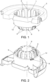
- the wringer of the present invention is formed by two parts, i.e., a wringer cone (1) and a base (2), that can be assembled together.
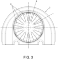
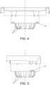
- Figures 1 to 5 depict the wringer with the two parts (1, 2) assembled together, wherein the different components can be seen, said components making up the wringer and being specified particularly in figures 6 and 7 which depict, respectively, the wringer cone (1) and the base (2), and will be used to provide a detailed description of each of the components making up the wringer, as they can all be seen with greater clarity.
- the wringer cone (1) is formed by a ring (3) from which a series of extensions (4) project, in a considerably perpendicular direction, uniformly separated from one another along the entire length of the ring (3).
- the extensions (4) end in rounded vertices (5) by which they are joined to prolongations (6) forming an angle.
- the vertices (5) show an accumulation of material by way of a thicknessing (7).
- the prolongations (6) are joined to one another by means of a circular base (8) having an elevation towards the volume defined by the prolongations (6), having a convex configuration once the wringer is assembled in a bucket.
- Both the extensions (4) and the prolongations (6) have a high capacity for elastic deformation. To that end, they are preferably manufactured from a thermoplastic material.
- the base (2) is configured to be attached to a bucket and to hold the wringer cone (1). To that end, it comprises a flat surface with a peripheral border having a U-shaped transversal cross-section in order to be placed on the edge of the bucket and an edge-free area, which faces the inside of the bucket when the base (2) is attached to the bucket, wherein at least one support is provided for attaching the handle of the mop when it is not being used.
- the wringer cone (1) Arranged on the flat surface of the base (2) there is a hole from which a skirt (10) projects which ends in an end with protuberances towards the two sides, towards the inside, forming a support ring (11), and towards the outside, forming an attachment rib (12).
- the support ring (11) is intended to act as a support for the ring (3) of the wringer cone (1).
- the wringer cone (1) comprises an anchoring (9) configured as a tab protruding from the circular base (8) the end of which has an arrowhead-shaped cross section in order to be anchored to the attachment rib (12).
- the radial attachment of the wringer cone (1) on the base (2) is carried out by means of attachment means consisting of a projection (13) located in the support ring (11) whereon there a recess is coupled, not depicted in the figures, located in the ring (3) of the wringer cone (1).
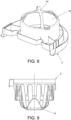
- Figure 8 depicts a base (2) in a second embodiment, wherein it incorporates a safety crosspiece (14), joined to the free end of the skirt (10) and configured in the form of two perpendicular arms, each pair having a U-shaped transversal cross section, such that the wringer cone (1) can be housed in the space configured by the two pairs of arms without making any contact.
- This crosspiece (14) is to prevent, by acting as a limiting stop, the wringer cone from being able to get over the support ring (11) and come off due to excessive pressure, or even breaking due to excessive elastic deformation of the material.
- Figures 9 and 10 clearly show the position of the wringer cone (1) with respect to the crosspiece (14) of the base (2).
- the operation is described below after having described the device.
- a mop with the wet head is introduced until it rests on the circular base (8).
- Pushing the head of the mop vertically downwards on the circular base (8) causes the prolongations (6) to close towards the inside, pressing on the head and then wringing it.
- the openings between the prolongations (6) are intended to drain the water from the head of the mop.
- the convex shape of the circular base (8) has two functions. On one hand, it prevents the water wrung from the head from being stored at the bottom of the wringer, rather said water falls into the bucket. On the other hand, it causes pressure to be applied to the inner strips of the head, improving the removal of water.
- the angle at which the prolongations (6) are joined to extensions (4) can be variable, taking into account that the larger the angle, the smaller the inner space in the wringer and the more effective the removal of water will be.
- the thicknessing (7) makes it so that the force applied to the mop can be fairly high, enabling the elastic deformation of the extensions (4), so that the prolongations (6) press on the head with a high force as well.
Landscapes
- Cleaning Implements For Floors, Carpets, Furniture, Walls, And The Like (AREA)
Claims (3)
- Vertikal betätigte Wringmaschine, die aus einem Auswringkegel (1) und einer Grundeinheit (2) gebildet ist, die in reversibler Weise zusammengebaut sind, wobei die Grundeinheit (2) eine ebene Fläche mit einem Loch aufweist, aus dem eine Schürze (10) herausragt, die in einem nach innen weisenden Stützring (11) und in einer nach außen weisenden Befestigungsrippe (12) mündet,
dadurch gekennzeichnet, dassder Auswringkegel (1) aufweist:- eine Reihe von Auslegern (4), die über die gesamte Länge eines Rings (3) gleichmäßig voneinander getrennt sind und in abgerundeten Scheitelbereichen (5) münden,- Verlängerungen (6), die mit den Auslegern (4) über die Scheitelbereiche (5) unter Bildung eines Winkels verbunden sind, und eine kreisförmige Basis (8), die eine Erhöhung in Richtung des durch die Verlängerungen (6) begrenzten Volumens aufweist, wobei,- die Ausleger (4) und die Verlängerungen (6) elastisch verformbar ausgebildet sind, und- die Scheitelbereiche (5) aufgrund einer Verdickung (7) eine Materialanhäufung, derart,dass das Vermögen erhöht ist, mittels eines Wischers größere Kräfte auf die kreisförmige Basis (8) aufzubringen. - Vertikal betätigte Wringmaschine nach Anspruch 1, dadurch gekennzeichnet, dass die Grundeinheit (2) einen Sicherheitsquerträger (14) aufweist, der mit dem freien Rand der Schürze (10) verbunden ist und aus zwei Paaren von senkrechten Armen gebildet ist, wobei jedes Paar von Armen einen U-förmigen transversalen Querschnitt aufweist, der ein Volumen zur Aufnahme des Auswringkegels (1) bildet.
- Vertikal betätigte Wringmaschine nach Anspruch 1 oder 2, dadurch gekennzeichnet, dass die Ausleger (4) und die Verlängerungen (6) aus einem thermoplastischen Material hergestellt sind.
Applications Claiming Priority (2)
| Application Number | Priority Date | Filing Date | Title |
|---|---|---|---|
| ES201830230U ES1208287Y (es) | 2018-03-05 | 2018-03-05 | Escurridor de accionamiento vertical |
| PCT/ES2019/070077 WO2019170939A1 (es) | 2018-03-05 | 2019-02-13 | Escurridor de accionamiento vertical |
Publications (4)
| Publication Number | Publication Date |
|---|---|
| EP3763276A1 EP3763276A1 (de) | 2021-01-13 |
| EP3763276A4 EP3763276A4 (de) | 2021-03-24 |
| EP3763276B1 true EP3763276B1 (de) | 2023-07-19 |
| EP3763276C0 EP3763276C0 (de) | 2023-07-19 |
Family
ID=61659609
Family Applications (1)
| Application Number | Title | Priority Date | Filing Date |
|---|---|---|---|
| EP19763546.9A Active EP3763276B1 (de) | 2018-03-05 | 2019-02-13 | Vertikal betätigte wringmaschine |
Country Status (3)
| Country | Link |
|---|---|
| EP (1) | EP3763276B1 (de) |
| ES (2) | ES1208287Y (de) |
| WO (1) | WO2019170939A1 (de) |
Cited By (1)
| Publication number | Priority date | Publication date | Assignee | Title |
|---|---|---|---|---|
| EP4559368A1 (de) * | 2023-11-16 | 2025-05-28 | SP Berner Plastic Group, S.L. | Vertikal betätigte moppauswringvorrichtung mit drehbewegung für einen moppeimer |
Families Citing this family (2)
| Publication number | Priority date | Publication date | Assignee | Title |
|---|---|---|---|---|
| USD1032138S1 (en) * | 2022-11-29 | 2024-06-18 | Dongyang Mingpin Commodity Co., Ltd. | Set of mop squeezer |
| USD1030171S1 (en) * | 2022-11-29 | 2024-06-04 | Dongyang Mingpin Commodity Co., Ltd. | Set of mop squeezer |
Family Cites Families (10)
| Publication number | Priority date | Publication date | Assignee | Title |
|---|---|---|---|---|
| ES283439A1 (es) | 1962-12-15 | 1963-02-01 | Navarro Rosa Fuensanta | Mejoras en la construcción de dispositivos para el cultivo de activado de plantas |
| DE4038372A1 (de) | 1990-12-01 | 1992-06-04 | Schlerf Coronet Werke | Auswringvorrichtung fuer reinigungselemente von feuchtreinigungsgeraeten |
| ES1041890Y (es) * | 1998-12-14 | 2000-01-16 | Reales Rosa Monsalve | Dispositivo para escurrir elementos de limpieza. |
| DE10045525C1 (de) | 2000-09-13 | 2002-02-07 | Freudenberg Carl Kg | Auswringvorrichtung |
| ES2238935B2 (es) | 2004-02-27 | 2006-12-01 | Sp Berner Plstic Group, S.L. | Escurridor para cubos friegasuelos. |
| CN2759372Y (zh) * | 2005-01-18 | 2006-02-22 | 上海镁嘉实业有限公司 | 圆拖挤干装置 |
| DE102006045615B3 (de) * | 2006-09-25 | 2007-10-11 | Carl Freudenberg Kg | Auswringvorrichtung |
| US9161673B2 (en) * | 2012-06-26 | 2015-10-20 | 3M Innovative Properties Company | Wringer for a bucket |
| AU2013302218B2 (en) * | 2012-08-08 | 2018-05-10 | E.D. Oates Pty Ltd | Mop bucket |
| ES1129630Y (es) * | 2014-10-01 | 2015-01-20 | Vondom S L U | Escurridor automatico |
-
2018
- 2018-03-05 ES ES201830230U patent/ES1208287Y/es active Active
-
2019
- 2019-02-13 WO PCT/ES2019/070077 patent/WO2019170939A1/es not_active Ceased
- 2019-02-13 ES ES19763546T patent/ES2956227T3/es active Active
- 2019-02-13 EP EP19763546.9A patent/EP3763276B1/de active Active
Cited By (1)
| Publication number | Priority date | Publication date | Assignee | Title |
|---|---|---|---|---|
| EP4559368A1 (de) * | 2023-11-16 | 2025-05-28 | SP Berner Plastic Group, S.L. | Vertikal betätigte moppauswringvorrichtung mit drehbewegung für einen moppeimer |
Also Published As
| Publication number | Publication date |
|---|---|
| EP3763276A4 (de) | 2021-03-24 |
| ES1208287Y (es) | 2018-06-21 |
| ES1208287U (es) | 2018-03-26 |
| ES2956227T3 (es) | 2023-12-15 |
| EP3763276C0 (de) | 2023-07-19 |
| EP3763276A1 (de) | 2021-01-13 |
| WO2019170939A1 (es) | 2019-09-12 |
Similar Documents
| Publication | Publication Date | Title |
|---|---|---|
| EP3763276B1 (de) | Vertikal betätigte wringmaschine | |
| CN211443243U (zh) | 一种放置稳定的锁扣式试剂盒 | |
| US7383604B2 (en) | Mop wringer | |
| US3525105A (en) | Sink strainer | |
| JP2004283557A (ja) | ピボット支持式濾板を備えた食品圧搾器 | |
| EP2028986A2 (de) | Moppeimer | |
| CN102258355B (zh) | 具有过滤洗涤用水的设备的用于拖把和类似物的绞干机 | |
| KR20140076813A (ko) | 배수구용 머리카락 절단기 | |
| US3383732A (en) | Mop bucket with separable strainer | |
| US20020108201A1 (en) | Wringer Basket for wet mops | |
| KR102253962B1 (ko) | 몹 헤드 | |
| KR101506421B1 (ko) | 스포이드 | |
| KR20120124678A (ko) | 탈수식 자루걸레 | |
| CN209789775U (zh) | 一种方便使用的自挤水拖把 | |
| JP6343074B1 (ja) | モップ装置 | |
| US1652800A (en) | Mop wringer | |
| CN115404663B (zh) | 内筒组件和具有其的洗衣机 | |
| US438467A (en) | Mop-wringer | |
| EP4388966B1 (de) | Moppeimer mit rädern | |
| KR101199087B1 (ko) | 스냅 단추 | |
| EP4559368A1 (de) | Vertikal betätigte moppauswringvorrichtung mit drehbewegung für einen moppeimer | |
| US921378A (en) | Lemon-juice extractor. | |
| CN215127353U (zh) | 咖啡机 | |
| KR102362689B1 (ko) | 착즙 드럼 | |
| KR102556204B1 (ko) | 물티슈 용기용 원터치 커버 |
Legal Events
| Date | Code | Title | Description |
|---|---|---|---|
| STAA | Information on the status of an ep patent application or granted ep patent |
Free format text: STATUS: THE INTERNATIONAL PUBLICATION HAS BEEN MADE |
|
| PUAI | Public reference made under article 153(3) epc to a published international application that has entered the european phase |
Free format text: ORIGINAL CODE: 0009012 |
|
| STAA | Information on the status of an ep patent application or granted ep patent |
Free format text: STATUS: REQUEST FOR EXAMINATION WAS MADE |
|
| 17P | Request for examination filed |
Effective date: 20200811 |
|
| AK | Designated contracting states |
Kind code of ref document: A1 Designated state(s): AL AT BE BG CH CY CZ DE DK EE ES FI FR GB GR HR HU IE IS IT LI LT LU LV MC MK MT NL NO PL PT RO RS SE SI SK SM TR |
|
| AX | Request for extension of the european patent |
Extension state: BA ME |
|
| A4 | Supplementary search report drawn up and despatched |
Effective date: 20210218 |
|
| RIC1 | Information provided on ipc code assigned before grant |
Ipc: A47L 13/58 20060101AFI20210212BHEP |
|
| DAV | Request for validation of the european patent (deleted) | ||
| DAX | Request for extension of the european patent (deleted) | ||
| GRAP | Despatch of communication of intention to grant a patent |
Free format text: ORIGINAL CODE: EPIDOSNIGR1 |
|
| STAA | Information on the status of an ep patent application or granted ep patent |
Free format text: STATUS: GRANT OF PATENT IS INTENDED |
|
| INTG | Intention to grant announced |
Effective date: 20230217 |
|
| GRAS | Grant fee paid |
Free format text: ORIGINAL CODE: EPIDOSNIGR3 |
|
| GRAA | (expected) grant |
Free format text: ORIGINAL CODE: 0009210 |
|
| STAA | Information on the status of an ep patent application or granted ep patent |
Free format text: STATUS: THE PATENT HAS BEEN GRANTED |
|
| AK | Designated contracting states |
Kind code of ref document: B1 Designated state(s): AL AT BE BG CH CY CZ DE DK EE ES FI FR GB GR HR HU IE IS IT LI LT LU LV MC MK MT NL NO PL PT RO RS SE SI SK SM TR |
|
| REG | Reference to a national code |
Ref country code: GB Ref legal event code: FG4D |
|
| REG | Reference to a national code |
Ref country code: CH Ref legal event code: EP |
|
| REG | Reference to a national code |
Ref country code: DE Ref legal event code: R096 Ref document number: 602019033096 Country of ref document: DE |
|
| REG | Reference to a national code |
Ref country code: IE Ref legal event code: FG4D |
|
| U01 | Request for unitary effect filed |
Effective date: 20230814 |
|
| U07 | Unitary effect registered |
Designated state(s): AT BE BG DE DK EE FI FR IT LT LU LV MT NL PT SE SI Effective date: 20230818 |
|
| REG | Reference to a national code |
Ref country code: LT Ref legal event code: MG9D |
|
| REG | Reference to a national code |
Ref country code: ES Ref legal event code: FG2A Ref document number: 2956227 Country of ref document: ES Kind code of ref document: T3 Effective date: 20231215 |
|
| PG25 | Lapsed in a contracting state [announced via postgrant information from national office to epo] |
Ref country code: GR Free format text: LAPSE BECAUSE OF FAILURE TO SUBMIT A TRANSLATION OF THE DESCRIPTION OR TO PAY THE FEE WITHIN THE PRESCRIBED TIME-LIMIT Effective date: 20231020 |
|
| PG25 | Lapsed in a contracting state [announced via postgrant information from national office to epo] |
Ref country code: IS Free format text: LAPSE BECAUSE OF FAILURE TO SUBMIT A TRANSLATION OF THE DESCRIPTION OR TO PAY THE FEE WITHIN THE PRESCRIBED TIME-LIMIT Effective date: 20231119 |
|
| PG25 | Lapsed in a contracting state [announced via postgrant information from national office to epo] |
Ref country code: RS Free format text: LAPSE BECAUSE OF FAILURE TO SUBMIT A TRANSLATION OF THE DESCRIPTION OR TO PAY THE FEE WITHIN THE PRESCRIBED TIME-LIMIT Effective date: 20230719 Ref country code: NO Free format text: LAPSE BECAUSE OF FAILURE TO SUBMIT A TRANSLATION OF THE DESCRIPTION OR TO PAY THE FEE WITHIN THE PRESCRIBED TIME-LIMIT Effective date: 20231019 Ref country code: IS Free format text: LAPSE BECAUSE OF FAILURE TO SUBMIT A TRANSLATION OF THE DESCRIPTION OR TO PAY THE FEE WITHIN THE PRESCRIBED TIME-LIMIT Effective date: 20231119 Ref country code: HR Free format text: LAPSE BECAUSE OF FAILURE TO SUBMIT A TRANSLATION OF THE DESCRIPTION OR TO PAY THE FEE WITHIN THE PRESCRIBED TIME-LIMIT Effective date: 20230719 Ref country code: GR Free format text: LAPSE BECAUSE OF FAILURE TO SUBMIT A TRANSLATION OF THE DESCRIPTION OR TO PAY THE FEE WITHIN THE PRESCRIBED TIME-LIMIT Effective date: 20231020 |
|
| PG25 | Lapsed in a contracting state [announced via postgrant information from national office to epo] |
Ref country code: PL Free format text: LAPSE BECAUSE OF FAILURE TO SUBMIT A TRANSLATION OF THE DESCRIPTION OR TO PAY THE FEE WITHIN THE PRESCRIBED TIME-LIMIT Effective date: 20230719 |
|
| U20 | Renewal fee for the european patent with unitary effect paid |
Year of fee payment: 6 Effective date: 20240213 |
|
| REG | Reference to a national code |
Ref country code: DE Ref legal event code: R097 Ref document number: 602019033096 Country of ref document: DE |
|
| PG25 | Lapsed in a contracting state [announced via postgrant information from national office to epo] |
Ref country code: SM Free format text: LAPSE BECAUSE OF FAILURE TO SUBMIT A TRANSLATION OF THE DESCRIPTION OR TO PAY THE FEE WITHIN THE PRESCRIBED TIME-LIMIT Effective date: 20230719 Ref country code: RO Free format text: LAPSE BECAUSE OF FAILURE TO SUBMIT A TRANSLATION OF THE DESCRIPTION OR TO PAY THE FEE WITHIN THE PRESCRIBED TIME-LIMIT Effective date: 20230719 Ref country code: CZ Free format text: LAPSE BECAUSE OF FAILURE TO SUBMIT A TRANSLATION OF THE DESCRIPTION OR TO PAY THE FEE WITHIN THE PRESCRIBED TIME-LIMIT Effective date: 20230719 Ref country code: SK Free format text: LAPSE BECAUSE OF FAILURE TO SUBMIT A TRANSLATION OF THE DESCRIPTION OR TO PAY THE FEE WITHIN THE PRESCRIBED TIME-LIMIT Effective date: 20230719 |
|
| PLBE | No opposition filed within time limit |
Free format text: ORIGINAL CODE: 0009261 |
|
| STAA | Information on the status of an ep patent application or granted ep patent |
Free format text: STATUS: NO OPPOSITION FILED WITHIN TIME LIMIT |
|
| 26N | No opposition filed |
Effective date: 20240422 |
|
| PG25 | Lapsed in a contracting state [announced via postgrant information from national office to epo] |
Ref country code: MC Free format text: LAPSE BECAUSE OF FAILURE TO SUBMIT A TRANSLATION OF THE DESCRIPTION OR TO PAY THE FEE WITHIN THE PRESCRIBED TIME-LIMIT Effective date: 20230719 |
|
| REG | Reference to a national code |
Ref country code: CH Ref legal event code: PL |
|
| PG25 | Lapsed in a contracting state [announced via postgrant information from national office to epo] |
Ref country code: CH Free format text: LAPSE BECAUSE OF NON-PAYMENT OF DUE FEES Effective date: 20240229 |
|
| GBPC | Gb: european patent ceased through non-payment of renewal fee |
Effective date: 20240213 |
|
| PG25 | Lapsed in a contracting state [announced via postgrant information from national office to epo] |
Ref country code: CH Free format text: LAPSE BECAUSE OF NON-PAYMENT OF DUE FEES Effective date: 20240229 |
|
| PG25 | Lapsed in a contracting state [announced via postgrant information from national office to epo] |
Ref country code: GB Free format text: LAPSE BECAUSE OF NON-PAYMENT OF DUE FEES Effective date: 20240213 |
|
| PG25 | Lapsed in a contracting state [announced via postgrant information from national office to epo] |
Ref country code: IE Free format text: LAPSE BECAUSE OF NON-PAYMENT OF DUE FEES Effective date: 20240213 |
|
| PG25 | Lapsed in a contracting state [announced via postgrant information from national office to epo] |
Ref country code: IE Free format text: LAPSE BECAUSE OF NON-PAYMENT OF DUE FEES Effective date: 20240213 Ref country code: GB Free format text: LAPSE BECAUSE OF NON-PAYMENT OF DUE FEES Effective date: 20240213 |
|
| U20 | Renewal fee for the european patent with unitary effect paid |
Year of fee payment: 7 Effective date: 20250204 |
|
| PGFP | Annual fee paid to national office [announced via postgrant information from national office to epo] |
Ref country code: ES Payment date: 20250303 Year of fee payment: 7 |
|
| PG25 | Lapsed in a contracting state [announced via postgrant information from national office to epo] |
Ref country code: CY Free format text: LAPSE BECAUSE OF FAILURE TO SUBMIT A TRANSLATION OF THE DESCRIPTION OR TO PAY THE FEE WITHIN THE PRESCRIBED TIME-LIMIT; INVALID AB INITIO Effective date: 20190213 |
|
| PG25 | Lapsed in a contracting state [announced via postgrant information from national office to epo] |
Ref country code: HU Free format text: LAPSE BECAUSE OF FAILURE TO SUBMIT A TRANSLATION OF THE DESCRIPTION OR TO PAY THE FEE WITHIN THE PRESCRIBED TIME-LIMIT; INVALID AB INITIO Effective date: 20190213 |
|
| PG25 | Lapsed in a contracting state [announced via postgrant information from national office to epo] |
Ref country code: TR Free format text: LAPSE BECAUSE OF FAILURE TO SUBMIT A TRANSLATION OF THE DESCRIPTION OR TO PAY THE FEE WITHIN THE PRESCRIBED TIME-LIMIT Effective date: 20230719 |