EP3763194A1 - Querförderer einer landwirtschaftlichen erntemaschine - Google Patents
Querförderer einer landwirtschaftlichen erntemaschine Download PDFInfo
- Publication number
- EP3763194A1 EP3763194A1 EP20185128.4A EP20185128A EP3763194A1 EP 3763194 A1 EP3763194 A1 EP 3763194A1 EP 20185128 A EP20185128 A EP 20185128A EP 3763194 A1 EP3763194 A1 EP 3763194A1
- Authority
- EP
- European Patent Office
- Prior art keywords
- cross conveyor
- drive unit
- conveyor
- conveyor belt
- cross
- Prior art date
- Legal status (The legal status is an assumption and is not a legal conclusion. Google has not performed a legal analysis and makes no representation as to the accuracy of the status listed.)
- Granted
Links
Images
Classifications
-
- A—HUMAN NECESSITIES
- A01—AGRICULTURE; FORESTRY; ANIMAL HUSBANDRY; HUNTING; TRAPPING; FISHING
- A01D—HARVESTING; MOWING
- A01D84/00—Haymakers not provided for in a single one of groups A01D76/00 - A01D82/00
-
- A—HUMAN NECESSITIES
- A01—AGRICULTURE; FORESTRY; ANIMAL HUSBANDRY; HUNTING; TRAPPING; FISHING
- A01D—HARVESTING; MOWING
- A01D57/00—Delivering mechanisms for harvesters or mowers
- A01D57/20—Delivering mechanisms for harvesters or mowers with conveyor belts
-
- B—PERFORMING OPERATIONS; TRANSPORTING
- B65—CONVEYING; PACKING; STORING; HANDLING THIN OR FILAMENTARY MATERIAL
- B65G—TRANSPORT OR STORAGE DEVICES, e.g. CONVEYORS FOR LOADING OR TIPPING, SHOP CONVEYOR SYSTEMS OR PNEUMATIC TUBE CONVEYORS
- B65G23/00—Driving gear for endless conveyors; Belt- or chain-tensioning arrangements
- B65G23/32—Driving gear for endless conveyors; Belt- or chain-tensioning arrangements for effecting drive at two or more points spaced along the length of the conveyors
- B65G23/36—Driving gear for endless conveyors; Belt- or chain-tensioning arrangements for effecting drive at two or more points spaced along the length of the conveyors comprising two or more driving motors each coupled to a separate driving element, e.g. at either end of the conveyors
Definitions
- the invention relates to a cross conveyor of an agricultural harvesting machine according to the preamble of claim 1.
- the cross conveyors can be designed as screw conveyors or as belt conveyors.
- the present invention relates to a cross conveyor of an agricultural harvesting machine with a cross conveyor belt, which is therefore designed as a belt conveyor.
- Such cross conveyors designed as belt conveyors are used, for example, in mergers or pick-up rakes or in mowers.
- the present invention is based on the object of creating a novel cross conveyor for an agricultural harvesting machine.
- each of the lateral deflection rollers is assigned a drive unit with the aid of which the cross conveyor belt can be driven. According to the invention it is therefore proposed that a drive unit is assigned to each of the two deflecting rollers of the cross conveyor, with the aid of which the cross conveyor belt can be driven.
- a good drive for the cross conveyor belt can thus be provided in both possible cross conveying directions.
- a so-called loose drum can also be prevented from sagging without a corresponding tensioning device.
- a relatively small drive unit can be used in the area of each deflecting roller, as a result of which space and cost advantages can be realized.
- a direction of rotation of the drive units can be reversed. In this way, proper drive of the cross conveyor belt can be ensured in both possible cross conveying directions of the cross conveyor.
- a first or upper run of the cross conveyor belt serves as a conveyor run and a second or lower run of the cross conveyor belt serves as a slack belt, with both the conveyor run and the slack belt being pulled by a first drive unit and pushed by a second drive unit in both possible conveying directions of the cross conveyor are.
- Both the conveying strand and the loose strand can be properly driven and tensioned in both conveying directions of the cross conveyor or cross conveyor belt.
- the respective drive unit has an electric motor and / or hydraulic motor. Electric motors and hydraulic motors are particularly suitable as drive units.
- Fig. 1 shows a structural unit 10 comprising a receiving element 11 and a transverse conveyor 12 of an agricultural harvesting machine, the receiving element 11 being designed as a so-called pick-up and the transverse conveyor 12 as a belt conveyor.
- a structural unit 10 is used in particular in a harvesting machine designed as a merger, a merger also being referred to as a pick-up rake.
- the receiving member 11 is arranged on a first longitudinal side of the transverse conveyor 12.
- a guide device 13 for the crop to be transported is arranged on an opposite, second transverse side of the transverse conveyor 12.
- the present invention relates to the design of the cross conveyor 12 shown in FIG Figs. 2 and 3 is shown in isolation.
- the transverse conveyor 12 is used to transport crop in a conveying direction running transversely to the direction of movement of the harvesting machine.
- the cross conveyor 12 has a cross conveyor belt 14 which is guided on two lateral deflection rollers 15, 16.
- a first or upper strand of the transverse conveyor belt 14 in the respective state of the transverse conveyor belt 14 is also referred to as a conveyor strand 19 and a second or lower strand of the transverse conveyor belt 14 is also referred to as a loose strand 20.
- the cross conveyor belt 14 is driven and guided on the deflection rollers 15, 16.
- each of the two deflection rollers 15, 16 is assigned a drive unit 17, 18, with the aid of which the cross conveyor belt 14 can be driven.
- the drive unit 17 is assigned to the deflection roller 15 and the drive unit 18 is assigned to the deflection roller 16.
- the two drive units 17, 18 are drive units whose direction of rotation can be reversed.
- the respective drive unit 17, 18 comprises an electric motor or a hydraulic motor.
- other drive systems can also be used to drive the deflection rollers 15, 16 and thus the transverse conveyor belt 14.
- the invention enables an improved drive of a cross conveyor 12 designed as a belt conveyor, that is to say the cross conveyor belt 14 of the cross conveyor 12.
- the cross conveyor belt 14 is guided on two lateral deflection rollers 15, 16.
- a drive unit 17, 18 is assigned to each of these lateral deflecting rollers 15, 16.
- the direction of rotation of the drive units 17, 18 is reversible. In both conveying directions of the transverse conveyor belt 14, both conveying strand 19 and loose strand 20 are pushed and pulled.
- the cross conveyor 12 according to the invention is used in particular in a merger or pick-up swather or also in a mower.
- the invention relates not only to the cross conveyor 12, but also to an agricultural harvesting machine which has at least one such cross conveyor 12.
- the agricultural harvesting machine is preferably a merger or pick-up swather or a mower.
Landscapes
- Life Sciences & Earth Sciences (AREA)
- Environmental Sciences (AREA)
- Structure Of Belt Conveyors (AREA)
- Harvester Elements (AREA)
Abstract
Description
- Die Erfindung betrifft einen Querförderer einer landwirtschaftlichen Erntemaschine nach dem Oberbegriff des Anspruchs 1.
- Landwirtschaftliche Erntemaschinen mit Querförderern sind aus der Praxis hinlänglich bekannt. Die Querförderer können dabei als Schneckenförderer oder auch als Bandförderer ausgeführt sein. Die hier vorliegende Erfindung betrifft einen Querförderer einer landwirtschaftlichen Erntemaschine mit einem Querförderband, der also als Bandförderer ausgebildet ist. Solche als Bandförderer ausgebildeten Querförderer kommen zum Beispiel in Mergern oder Pickup-Schwadern oder auch in Mähwerken zum Einsatz.
- Bei aus der Praxis bekannten Querförderern, die ein Querförderband aufweisen, welches an seitlichen Umlenkrollen geführt ist, bereitet bislang der ordnungsgemäße Antrieb des Querförderbands Schwierigkeiten. Insbesondere bei relativ langen Querförderbändern, bei welchen also der Abstand zwischen den Umlenkrollen relativ groß ist, stellt der ordnungsgemäße Antrieb des Querförderbands ein Problem dar. Es besteht daher Bedarf an einem neuartigen Querförderer, der besser angetrieben werden kann.
- Hiervon ausgehend liegt der vorliegenden Erfindung die Aufgabe zugrunde, einen neuartigen Querförderer einer landwirtschaftlichen Erntemaschine zu schaffen.
- Diese Aufgabe wird durch einen Querförderer einer landwirtschaftlichen Erntemaschine nach Anspruch 1 gelöst.
- Erfindungsgemäß ist jeder der seitlichen Umlenkrollen jeweils eine Antriebseinheit zugordnet, mit Hilfe derer das Querförderband antreibbar ist. Erfindungsgemäß wird also vorgeschlagen, dass beiden Umlenkrollen des Querförderers jeweils eine Antriebseinheit zugeordnet ist, mithilfe derer das Querförderband angetrieben werden kann.
- Das Verwenden einer Antriebseinheit je Umlenkrolle verfügt über eine Vielzahl von Vorteilen. So kann in beiden möglichen Querförderrichtungen ein guter Antrieb des Querförderbands bereitgestellt werden. Ein Durchhängen eines sogenannten Lostrum kann auch ohne entsprechende Spanneinrichtung verhindert werden. Ferner kann im Bereich jeder Umlenkrolle eine relativ kleine Antriebseinheit genutzt werden, wodurch sich Bauraum- und Kostenvorteile realisieren lassen.
- Nach einer vorteilhaften Weiterbildung ist eine Drehrichtung der Antriebseinheiten umkehrbar. Hiermit kann in beiden möglichen Querförderrichtungen des Querförderers ein ordnungsgemäßer Antrieb des Querförderbands gewährleistet werden.
- Nach einer vorteilhaften Weiterbildung dient ein erster oder oberer Trum des Querförderbands als Fördertrum und ein zweiter oder unterer Trum des Querförderbands als Lostrum, wobei sowohl der Fördertrum als auch der Lostrum in beiden möglichen Förderrichtungen des Querförderers von einer ersten Antriebseinheit gezogen und von einer zweiten Antriebseinheit geschoben sind. Sowohl Fördertrum als auch Lostrum können in beiden Förderrichtungen des Querförderers bzw. Querförderbands ordnungsgemäß angetrieben und gespannt werden.
- Nach einer vorteilhaften Weiterbildung weist die jeweilige Antriebseinheit einen Elektromotor und/oder Hydraulikmotor auf. Elektromotoren und Hydraulikmotoren sind als Antriebseinheiten besonders geeignet.
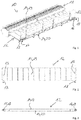
- Bevorzugte Weiterbildungen der Erfindung ergeben sich aus den Unteransprüchen und der nachfolgenden Beschreibung. Ausführungsbeispiele der Erfindung werden, ohne hierauf beschränkt zu sein, an Hand der Zeichnung näher erläutert. Dabei zeigt:
- Fig. 1
- eine perspektivische Rückansicht einer Baueinheit aus einem erfindungsgemäßen Querförderer und einem Aufnahmeorgan einer als Merger oder Pickup-Schwader ausgebildeten landwirtschaftlichen Erntemaschine;
- Fig. 2
- den erfindungsgemäßen Querförderer in Draufsicht;
- Fig. 3
- den erfindungsgemäßen Querförderer in Rückansicht.
-
Fig. 1 zeigt eine Baueinheit 10 aus einem Aufnahmeorgan 11 und einem Querförderer 12 einer landwirtschaftlichen Erntemaschine, wobei das Aufnahmeorgan 11 als sogenannte Pickup und der Querförderer 12 als Bandförderer ausgebildet ist. Eine derartige Baueinheit 10 kommt insbesondere bei einer als Merger ausgebildeten Erntemaschine zum Einsatz, wobei ein Merger auch als Pickup-Schwader bezeichnet wird. Das Aufnahmeorgan 11 ist zu einer ersten Längsseite des Querförderers 12 angeordnet. Zu einer gegenüberliegenden zweiten Querseite des Querförderers 12 ist eine Führungseinrichtung 13 für das zu transportierende Erntegut angeordnet. - Die hier vorliegende Erfindung betrifft die Ausgestaltung des Querförderers 12, der in
Fig. 2 und 3 in Alleindarstellung gezeigt ist. Der Querförderer 12 dient dem Transport von Erntegut in einer quer zur Fortbewegungsrichtung der Erntemaschine verlaufenden Förderrichtung. - Der Querförderer 12 verfügt über ein Querförderband 14, das an zwei seitlichen Umlenkrollen 15, 16 geführt ist.
- Ein im jeweiligen Zustand des Querförderbands 14 erster oder oberer Trum des Querförderbands 14 wird auch als Fördertrum 19 und ein zweiter oder unterer Trum des Querförderbands 14 wird auch als Lostrum 20 bezeichnet.
- Beim Transport von Erntegut mithilfe des Querförders12 wird das Querförderband 14 angetrieben und an den Umlenkrollen 15, 16 geführt.
- Bei dem erfindungsgemäßen Querförderer 12 ist vorgesehen, dass jeder der beiden Umlenkrollen 15, 16 jeweils eine Antriebseinheit 17, 18 zugeordnet ist, mithilfe derer das Querförderband 14 antreibbar ist. So ist der Umlenkrolle 15 die Antriebseinheit 17 und der Umlenkrolle 16 ist die Antriebseinheit 18 zugeordnet. Bei den beiden Antriebseinheiten 17, 18 handelt es sich dabei um Antriebseinheiten, deren Drehrichtung umkehrbar ist.
- Insbesondere umfasst die jeweilige Antriebseinheit 17, 18 einen Elektromotor oder auch einen Hydraulikmotor. Es können jedoch auch andere Antriebssysteme zum Antreiben der Umlenkrollen 15, 16 und damit des Querförderbands 14 zum Einsatz kommen.
- Dann, wenn im Bereich beider Umlenkrollen 15, 16 jeweils eine Antriebseinheit 17, 18 vorhanden ist, und dann, wenn die Drehrichtung dieser Antriebseinheiten 17, 18 umkehrbar ist, wird in beiden möglichen Förderrichtungen des Querförderers 14 der jeweilige Fördertrum 19 sowie der jeweilige Lostrum 20 von einer ersten Antriebseinheit gezogen und von einer zweiten Antriebseinheit geschoben. Hierdurch kann gewährleistet werden, dass in beiden Förderrichtungen des Querförderers 14 sowohl der jeweilige Fördertrum 19 als auch der jeweilige Lostrum 20 gespannt ist und nicht durchhängt. Auf separate Spanneinrichtungen kann so verzichtet werden. Dies ist insbesondere dann von Vorteil, wenn der Abstand zwischen den beiden Umlenkrollen 15, 16 relativ groß und damit die Länge des Querförderbands 14 relativ lang ist.
- Die Erfindung ermöglicht einen verbesserten Antrieb eines als Bandförderer ausgebildeten Querförderers 12, also des Querförderbands 14 des Querförderers 12. Das Querförderband 14 ist an zwei seitlichen Umlenkrollen 15, 16 geführt. Jeder dieser seitlichen Umlenkrollen 15, 16 ist jeweils eine Antriebseinheit 17, 18 zugeordnet. Die Drehrichtung der Antriebseinheiten 17, 18 ist umkehrbar. In beiden Förderrichtungen des Querförderbands 14 werden sowohl Fördertrum 19 als auch Lostrum 20 geschoben und gezogen.
- Der erfindungsgemäße Querförderer 12 findet insbesondere bei einem Merger oder Pickup-Schwader oder auch bei einem Mähwerk Einsatz.
- Die Erfindung betrifft nicht nur den Querförderer 12, sondern auch eine landwirtschaftliche Erntemaschine, die mindestens einen derartigen Querförderer 12 aufweist. Wie bereits ausgeführt, handelt es sich bei der landwirtschaftlichen Erntemaschine dabei vorzugsweise um einen Merger bzw. Pickup-Schwader oder auch um ein Mähwerk.
-
- 10
- Baueinheit
- 11
- Aufnahmeorgan
- 12
- Querförderer
- 13
- Führungseinrichtung
- 14
- Querförderband
- 15
- Umlenkrolle
- 16
- Umlenkrolle
- 17
- Antriebseinheit
- 18
- Antriebseinheit
- 19
- Fördertrum
- 20
- Lostrum
Claims (8)
- Querförderer (12) einer landwirtschaftlichen Erntemaschine, um Erntegut in einer quer zur Fortbewegungsrichtung der Erntemaschine verlaufenden Förderrichtung zu fördern,mit einem Querförderband (14),mit seitlichen Umlenkrollen (15, 16), an welchen das Querförderband (14) geführt ist, dadurch gekennzeichnet, dassjeder der seitlichen Umlenkrollen (15, 16) jeweils eine Antriebseinheit (17, 18) zugordnet ist, mit Hilfe derer das Querförderband (14) antreibbar ist.
- Querförderer nach Anspruch 1, dadurch gekennzeichnet, dass eine Drehrichtung der Antriebseinheiten (17, 18) umkehrbar ist.
- Querförderer nach Anspruch 1 oder 2, dadurch gekennzeichnet, dass ein erster oder oberer Trum des Querförderbands (14) als Fördertrum (19) und ein zweiter oder unterer Trum des Querförderbands (14) als Lostrum (20) dient, wobei sowohl der Fördertrum (19) als auch der Lostrum (20) in beiden möglichen Förderrichtungen des Querförderers (14) von einer ersten Antriebseinheit (17, 18) gezogen und von einer zweiten Antriebseinheit (18, 17) geschoben sind.
- Querförderer nach einem der Ansprüche 1 bis 3, dadurch gekennzeichnet, dass die jeweilige Antriebseinheit (17, 18) einen Elektromotor aufweist.
- Querförderer nach einem der Ansprüche 1 bis 4, dadurch gekennzeichnet, dass die jeweilige Antriebseinheit (17, 18) einen Hydraulikmotor aufweist.
- Landwirtschaftliche Erntemaschine mit mindestens einem Querförderer (12) nach einem der Ansprüche 1 bis 5.
- Landwirtschaftliche Erntemaschine nach Anspruch 6, dadurch gekennzeichnet, dass dieselbe ein Merger oder Pickup-Schwader ist.
- Landwirtschaftliche Erntemaschine nach Anspruch 6, dadurch gekennzeichnet, dass dieselbe ein Mähwerk ist.
Priority Applications (1)
| Application Number | Priority Date | Filing Date | Title |
|---|---|---|---|
| SI202030529T SI3763194T1 (sl) | 2019-07-10 | 2020-07-10 | Prečni transporter kmetijskega žetvenega stroja |
Applications Claiming Priority (1)
| Application Number | Priority Date | Filing Date | Title |
|---|---|---|---|
| DE102019118740.0A DE102019118740A1 (de) | 2019-07-10 | 2019-07-10 | Querförderer einer landwirtschaftlichen Erntemaschine |
Publications (2)
| Publication Number | Publication Date |
|---|---|
| EP3763194A1 true EP3763194A1 (de) | 2021-01-13 |
| EP3763194B1 EP3763194B1 (de) | 2024-09-11 |
Family
ID=71575110
Family Applications (1)
| Application Number | Title | Priority Date | Filing Date |
|---|---|---|---|
| EP20185128.4A Active EP3763194B1 (de) | 2019-07-10 | 2020-07-10 | Querförderer einer landwirtschaftlichen erntemaschine |
Country Status (5)
| Country | Link |
|---|---|
| US (1) | US20210007280A1 (de) |
| EP (1) | EP3763194B1 (de) |
| DE (1) | DE102019118740A1 (de) |
| PL (1) | PL3763194T3 (de) |
| SI (1) | SI3763194T1 (de) |
Citations (3)
| Publication number | Priority date | Publication date | Assignee | Title |
|---|---|---|---|---|
| EP0199299A1 (de) * | 1985-04-19 | 1986-10-29 | Amazonen-Werke H. Dreyer GmbH & Co. KG | Grossflächenstreuer, insbesondere Düngerstreuer |
| US20050126153A1 (en) * | 2002-02-12 | 2005-06-16 | Kuhn S.A. | Agricultural machine for bundling products lying on the ground |
| EP2042023A1 (de) * | 2007-09-28 | 2009-04-01 | JF-Fabriken - J. Freudendahl A/S | Mäher mit Förderband |
Family Cites Families (16)
| Publication number | Priority date | Publication date | Assignee | Title |
|---|---|---|---|---|
| US2652675A (en) * | 1950-08-15 | 1953-09-22 | John L Hughes | Grain cutting and windrow forming implement |
| US3473613A (en) * | 1967-04-26 | 1969-10-21 | Fmc Corp | Tomato harvester |
| US4512140A (en) * | 1983-09-16 | 1985-04-23 | Sperry Corporation | Stub draper drive for draper header |
| US4590751A (en) * | 1984-06-20 | 1986-05-27 | Deere & Company | Double windrowing attachment for harvester |
| FR2664126A1 (fr) * | 1990-07-03 | 1992-01-10 | Gabard Raymond | Tondeuse a gazon. |
| US6205757B1 (en) * | 1999-02-19 | 2001-03-27 | Byron Enterprises, Inc. | Windrow merging machine and method of merging windrows |
| US6116006A (en) * | 1999-05-27 | 2000-09-12 | Deere & Company | Hydraulic system for a detachable implement |
| US7310929B2 (en) * | 2003-03-31 | 2007-12-25 | Oxbo International Corporation | Windrow merging apparatus |
| US8091331B2 (en) * | 2008-08-15 | 2012-01-10 | Oxbo International Corporation | Windrow merger |
| US8527157B2 (en) * | 2010-04-28 | 2013-09-03 | Deere & Company | Agricultural combine and draper header |
| US8656694B2 (en) * | 2011-01-12 | 2014-02-25 | Agco Corporation | Auxiliary drive motor for hay conditioner on a windrower header |
| US8833044B2 (en) * | 2012-10-04 | 2014-09-16 | Deere & Company | Harvesting head with conveyor drive system |
| US9717179B2 (en) * | 2014-02-25 | 2017-08-01 | Cnh America Llc | Hydraulic system for a header of an agricultural harvester |
| US10039235B2 (en) * | 2016-04-25 | 2018-08-07 | Kuhn North America, Inc. | Merger and merger assembly with first and second belts |
| US10420284B2 (en) * | 2017-10-31 | 2019-09-24 | Deere & Company | Slip controller for side conveyors of a draper harvesting head |
| US11540445B2 (en) * | 2018-04-27 | 2023-01-03 | Cnh Industrial America Llc | Crop merger system for harvester and methods of using the same |
-
2019
- 2019-07-10 DE DE102019118740.0A patent/DE102019118740A1/de not_active Withdrawn
-
2020
- 2020-07-08 US US16/923,875 patent/US20210007280A1/en not_active Abandoned
- 2020-07-10 EP EP20185128.4A patent/EP3763194B1/de active Active
- 2020-07-10 SI SI202030529T patent/SI3763194T1/sl unknown
- 2020-07-10 PL PL20185128.4T patent/PL3763194T3/pl unknown
Patent Citations (3)
| Publication number | Priority date | Publication date | Assignee | Title |
|---|---|---|---|---|
| EP0199299A1 (de) * | 1985-04-19 | 1986-10-29 | Amazonen-Werke H. Dreyer GmbH & Co. KG | Grossflächenstreuer, insbesondere Düngerstreuer |
| US20050126153A1 (en) * | 2002-02-12 | 2005-06-16 | Kuhn S.A. | Agricultural machine for bundling products lying on the ground |
| EP2042023A1 (de) * | 2007-09-28 | 2009-04-01 | JF-Fabriken - J. Freudendahl A/S | Mäher mit Förderband |
Also Published As
| Publication number | Publication date |
|---|---|
| PL3763194T3 (pl) | 2025-02-24 |
| DE102019118740A1 (de) | 2021-01-14 |
| SI3763194T1 (sl) | 2025-02-28 |
| US20210007280A1 (en) | 2021-01-14 |
| EP3763194B1 (de) | 2024-09-11 |
Similar Documents
| Publication | Publication Date | Title |
|---|---|---|
| EP0591688A2 (de) | Selbstfahrender Mähdrescher | |
| DE1941113A1 (de) | Maehwerk | |
| DE102019213022A1 (de) | Fördersystem | |
| EP0976316A1 (de) | Vorrichtung zum Ernten von stengeligem Erntegut | |
| DE60305328T2 (de) | Förderband | |
| DE2736005A1 (de) | Reihenvorsatzgeraet fuer feldhaecksler | |
| EP0651940A1 (de) | Federzinken, Fördervorrichtung und Erntemaschine | |
| EP2298057B1 (de) | Vorrichtung zum Fördern und Reinigen von Erntegut in Form von Wurzelfrüchten, insbesondere in Form von Zuckerrüben, sowie Reinigungslader mit einer solchen Vorrichtung | |
| DD246694A5 (de) | Selbstfahrender maehdrescher | |
| DE102018222481A1 (de) | Zugmittel, vorzugsweise Riemen, für einen Schrägförderer eines Mähdreschers | |
| EP3763194B1 (de) | Querförderer einer landwirtschaftlichen erntemaschine | |
| DE102010017502A1 (de) | Messerbalken | |
| DE4132246A1 (de) | Foerderer mit einem endlosen zugmittel und abweiser hierfuer | |
| DE3050655C2 (de) | ||
| EP0359904B1 (de) | Mehrreihiger Kartoffelschubroder | |
| DD151252A5 (de) | Schuettlerloser selbstfahrender maehdrescher | |
| DE2730308C3 (de) | Ladewagen für Halmgut | |
| DE102019105170A1 (de) | Mähwerk | |
| DE2749558C3 (de) | Kartoffel-Sammelerntemaschine | |
| EP3536141A1 (de) | Querförderer einer landwirtschaftlichen erntemaschine | |
| DE2656222A1 (de) | Erntevorsatz an feldhaeckslern zum aufnehmen und weiterfuehren von in reihe stehenden halmfruechten | |
| EP0432701B1 (de) | Stabband für Stabbandförderer | |
| DE3031637C2 (de) | ||
| EP0482316A1 (de) | Kartoffelerntemaschine | |
| EP4606205A1 (de) | Schrägförderer für eine erntemaschine |
Legal Events
| Date | Code | Title | Description |
|---|---|---|---|
| PUAI | Public reference made under article 153(3) epc to a published international application that has entered the european phase |
Free format text: ORIGINAL CODE: 0009012 |
|
| STAA | Information on the status of an ep patent application or granted ep patent |
Free format text: STATUS: THE APPLICATION HAS BEEN PUBLISHED |
|
| AK | Designated contracting states |
Kind code of ref document: A1 Designated state(s): AL AT BE BG CH CY CZ DE DK EE ES FI FR GB GR HR HU IE IS IT LI LT LU LV MC MK MT NL NO PL PT RO RS SE SI SK SM TR |
|
| AX | Request for extension of the european patent |
Extension state: BA ME |
|
| STAA | Information on the status of an ep patent application or granted ep patent |
Free format text: STATUS: REQUEST FOR EXAMINATION WAS MADE |
|
| 17P | Request for examination filed |
Effective date: 20210713 |
|
| RBV | Designated contracting states (corrected) |
Designated state(s): AL AT BE BG CH CY CZ DE DK EE ES FI FR GB GR HR HU IE IS IT LI LT LU LV MC MK MT NL NO PL PT RO RS SE SI SK SM TR |
|
| P01 | Opt-out of the competence of the unified patent court (upc) registered |
Effective date: 20230712 |
|
| GRAP | Despatch of communication of intention to grant a patent |
Free format text: ORIGINAL CODE: EPIDOSNIGR1 |
|
| STAA | Information on the status of an ep patent application or granted ep patent |
Free format text: STATUS: GRANT OF PATENT IS INTENDED |
|
| INTG | Intention to grant announced |
Effective date: 20240209 |
|
| GRAS | Grant fee paid |
Free format text: ORIGINAL CODE: EPIDOSNIGR3 |
|
| GRAA | (expected) grant |
Free format text: ORIGINAL CODE: 0009210 |
|
| STAA | Information on the status of an ep patent application or granted ep patent |
Free format text: STATUS: THE PATENT HAS BEEN GRANTED |
|
| AK | Designated contracting states |
Kind code of ref document: B1 Designated state(s): AL AT BE BG CH CY CZ DE DK EE ES FI FR GB GR HR HU IE IS IT LI LT LU LV MC MK MT NL NO PL PT RO RS SE SI SK SM TR |
|
| REG | Reference to a national code |
Ref country code: GB Ref legal event code: FG4D Free format text: NOT ENGLISH |
|
| REG | Reference to a national code |
Ref country code: CH Ref legal event code: EP |
|
| REG | Reference to a national code |
Ref country code: DE Ref legal event code: R096 Ref document number: 502020009172 Country of ref document: DE |
|
| REG | Reference to a national code |
Ref country code: IE Ref legal event code: FG4D Free format text: LANGUAGE OF EP DOCUMENT: GERMAN |
|
| REG | Reference to a national code |
Ref country code: NL Ref legal event code: FP |
|
| REG | Reference to a national code |
Ref country code: LT Ref legal event code: MG9D |
|
| PG25 | Lapsed in a contracting state [announced via postgrant information from national office to epo] |
Ref country code: NO Free format text: LAPSE BECAUSE OF FAILURE TO SUBMIT A TRANSLATION OF THE DESCRIPTION OR TO PAY THE FEE WITHIN THE PRESCRIBED TIME-LIMIT Effective date: 20241211 |
|
| PG25 | Lapsed in a contracting state [announced via postgrant information from national office to epo] |
Ref country code: GR Free format text: LAPSE BECAUSE OF FAILURE TO SUBMIT A TRANSLATION OF THE DESCRIPTION OR TO PAY THE FEE WITHIN THE PRESCRIBED TIME-LIMIT Effective date: 20241212 Ref country code: FI Free format text: LAPSE BECAUSE OF FAILURE TO SUBMIT A TRANSLATION OF THE DESCRIPTION OR TO PAY THE FEE WITHIN THE PRESCRIBED TIME-LIMIT Effective date: 20240911 |
|
| PG25 | Lapsed in a contracting state [announced via postgrant information from national office to epo] |
Ref country code: BG Free format text: LAPSE BECAUSE OF FAILURE TO SUBMIT A TRANSLATION OF THE DESCRIPTION OR TO PAY THE FEE WITHIN THE PRESCRIBED TIME-LIMIT Effective date: 20240911 |
|
| PG25 | Lapsed in a contracting state [announced via postgrant information from national office to epo] |
Ref country code: LV Free format text: LAPSE BECAUSE OF FAILURE TO SUBMIT A TRANSLATION OF THE DESCRIPTION OR TO PAY THE FEE WITHIN THE PRESCRIBED TIME-LIMIT Effective date: 20240911 |
|
| PG25 | Lapsed in a contracting state [announced via postgrant information from national office to epo] |
Ref country code: HR Free format text: LAPSE BECAUSE OF FAILURE TO SUBMIT A TRANSLATION OF THE DESCRIPTION OR TO PAY THE FEE WITHIN THE PRESCRIBED TIME-LIMIT Effective date: 20240911 |
|
| PG25 | Lapsed in a contracting state [announced via postgrant information from national office to epo] |
Ref country code: RS Free format text: LAPSE BECAUSE OF FAILURE TO SUBMIT A TRANSLATION OF THE DESCRIPTION OR TO PAY THE FEE WITHIN THE PRESCRIBED TIME-LIMIT Effective date: 20241211 Ref country code: ES Free format text: LAPSE BECAUSE OF FAILURE TO SUBMIT A TRANSLATION OF THE DESCRIPTION OR TO PAY THE FEE WITHIN THE PRESCRIBED TIME-LIMIT Effective date: 20240911 |
|
| PG25 | Lapsed in a contracting state [announced via postgrant information from national office to epo] |
Ref country code: RS Free format text: LAPSE BECAUSE OF FAILURE TO SUBMIT A TRANSLATION OF THE DESCRIPTION OR TO PAY THE FEE WITHIN THE PRESCRIBED TIME-LIMIT Effective date: 20241211 Ref country code: NO Free format text: LAPSE BECAUSE OF FAILURE TO SUBMIT A TRANSLATION OF THE DESCRIPTION OR TO PAY THE FEE WITHIN THE PRESCRIBED TIME-LIMIT Effective date: 20241211 Ref country code: LV Free format text: LAPSE BECAUSE OF FAILURE TO SUBMIT A TRANSLATION OF THE DESCRIPTION OR TO PAY THE FEE WITHIN THE PRESCRIBED TIME-LIMIT Effective date: 20240911 Ref country code: HR Free format text: LAPSE BECAUSE OF FAILURE TO SUBMIT A TRANSLATION OF THE DESCRIPTION OR TO PAY THE FEE WITHIN THE PRESCRIBED TIME-LIMIT Effective date: 20240911 Ref country code: GR Free format text: LAPSE BECAUSE OF FAILURE TO SUBMIT A TRANSLATION OF THE DESCRIPTION OR TO PAY THE FEE WITHIN THE PRESCRIBED TIME-LIMIT Effective date: 20241212 Ref country code: FI Free format text: LAPSE BECAUSE OF FAILURE TO SUBMIT A TRANSLATION OF THE DESCRIPTION OR TO PAY THE FEE WITHIN THE PRESCRIBED TIME-LIMIT Effective date: 20240911 Ref country code: ES Free format text: LAPSE BECAUSE OF FAILURE TO SUBMIT A TRANSLATION OF THE DESCRIPTION OR TO PAY THE FEE WITHIN THE PRESCRIBED TIME-LIMIT Effective date: 20240911 Ref country code: BG Free format text: LAPSE BECAUSE OF FAILURE TO SUBMIT A TRANSLATION OF THE DESCRIPTION OR TO PAY THE FEE WITHIN THE PRESCRIBED TIME-LIMIT Effective date: 20240911 |
|
| PG25 | Lapsed in a contracting state [announced via postgrant information from national office to epo] |
Ref country code: IS Free format text: LAPSE BECAUSE OF FAILURE TO SUBMIT A TRANSLATION OF THE DESCRIPTION OR TO PAY THE FEE WITHIN THE PRESCRIBED TIME-LIMIT Effective date: 20250111 Ref country code: PT Free format text: LAPSE BECAUSE OF FAILURE TO SUBMIT A TRANSLATION OF THE DESCRIPTION OR TO PAY THE FEE WITHIN THE PRESCRIBED TIME-LIMIT Effective date: 20250113 |
|
| PG25 | Lapsed in a contracting state [announced via postgrant information from national office to epo] |
Ref country code: RO Free format text: LAPSE BECAUSE OF FAILURE TO SUBMIT A TRANSLATION OF THE DESCRIPTION OR TO PAY THE FEE WITHIN THE PRESCRIBED TIME-LIMIT Effective date: 20240911 Ref country code: SM Free format text: LAPSE BECAUSE OF FAILURE TO SUBMIT A TRANSLATION OF THE DESCRIPTION OR TO PAY THE FEE WITHIN THE PRESCRIBED TIME-LIMIT Effective date: 20240911 |
|
| PG25 | Lapsed in a contracting state [announced via postgrant information from national office to epo] |
Ref country code: EE Free format text: LAPSE BECAUSE OF FAILURE TO SUBMIT A TRANSLATION OF THE DESCRIPTION OR TO PAY THE FEE WITHIN THE PRESCRIBED TIME-LIMIT Effective date: 20240911 |
|
| PG25 | Lapsed in a contracting state [announced via postgrant information from national office to epo] |
Ref country code: CZ Free format text: LAPSE BECAUSE OF FAILURE TO SUBMIT A TRANSLATION OF THE DESCRIPTION OR TO PAY THE FEE WITHIN THE PRESCRIBED TIME-LIMIT Effective date: 20240911 |
|
| PG25 | Lapsed in a contracting state [announced via postgrant information from national office to epo] |
Ref country code: SK Free format text: LAPSE BECAUSE OF FAILURE TO SUBMIT A TRANSLATION OF THE DESCRIPTION OR TO PAY THE FEE WITHIN THE PRESCRIBED TIME-LIMIT Effective date: 20240911 |
|
| REG | Reference to a national code |
Ref country code: DE Ref legal event code: R097 Ref document number: 502020009172 Country of ref document: DE |
|
| PGFP | Annual fee paid to national office [announced via postgrant information from national office to epo] |
Ref country code: PL Payment date: 20250630 Year of fee payment: 6 |
|
| PG25 | Lapsed in a contracting state [announced via postgrant information from national office to epo] |
Ref country code: DK Free format text: LAPSE BECAUSE OF FAILURE TO SUBMIT A TRANSLATION OF THE DESCRIPTION OR TO PAY THE FEE WITHIN THE PRESCRIBED TIME-LIMIT Effective date: 20240911 |
|
| PLBE | No opposition filed within time limit |
Free format text: ORIGINAL CODE: 0009261 |
|
| STAA | Information on the status of an ep patent application or granted ep patent |
Free format text: STATUS: NO OPPOSITION FILED WITHIN TIME LIMIT |
|
| PGFP | Annual fee paid to national office [announced via postgrant information from national office to epo] |
Ref country code: SI Payment date: 20250626 Year of fee payment: 6 |
|
| PGFP | Annual fee paid to national office [announced via postgrant information from national office to epo] |
Ref country code: NL Payment date: 20250721 Year of fee payment: 6 |
|
| 26N | No opposition filed |
Effective date: 20250612 |
|
| PG25 | Lapsed in a contracting state [announced via postgrant information from national office to epo] |
Ref country code: SE Free format text: LAPSE BECAUSE OF FAILURE TO SUBMIT A TRANSLATION OF THE DESCRIPTION OR TO PAY THE FEE WITHIN THE PRESCRIBED TIME-LIMIT Effective date: 20240911 |
|
| PGFP | Annual fee paid to national office [announced via postgrant information from national office to epo] |
Ref country code: DE Payment date: 20250722 Year of fee payment: 6 |
|
| PGFP | Annual fee paid to national office [announced via postgrant information from national office to epo] |
Ref country code: IT Payment date: 20250724 Year of fee payment: 6 |
|
| PGFP | Annual fee paid to national office [announced via postgrant information from national office to epo] |
Ref country code: FR Payment date: 20250725 Year of fee payment: 6 Ref country code: AT Payment date: 20250722 Year of fee payment: 6 |
|
| REG | Reference to a national code |
Ref country code: CH Ref legal event code: H13 Free format text: ST27 STATUS EVENT CODE: U-0-0-H10-H13 (AS PROVIDED BY THE NATIONAL OFFICE) Effective date: 20260224 |
|
| PG25 | Lapsed in a contracting state [announced via postgrant information from national office to epo] |
Ref country code: LU Free format text: LAPSE BECAUSE OF NON-PAYMENT OF DUE FEES Effective date: 20250710 |
|
| GBPC | Gb: european patent ceased through non-payment of renewal fee |
Effective date: 20250710 |
|
| REG | Reference to a national code |
Ref country code: BE Ref legal event code: MM Effective date: 20250731 |
|
| PG25 | Lapsed in a contracting state [announced via postgrant information from national office to epo] |
Ref country code: GB Free format text: LAPSE BECAUSE OF NON-PAYMENT OF DUE FEES Effective date: 20250710 |
|
| PG25 | Lapsed in a contracting state [announced via postgrant information from national office to epo] |
Ref country code: BE Free format text: LAPSE BECAUSE OF NON-PAYMENT OF DUE FEES Effective date: 20250731 |
|
| PG25 | Lapsed in a contracting state [announced via postgrant information from national office to epo] |
Ref country code: CH Free format text: LAPSE BECAUSE OF NON-PAYMENT OF DUE FEES Effective date: 20250731 |
|
| PG25 | Lapsed in a contracting state [announced via postgrant information from national office to epo] |
Ref country code: LT Free format text: LAPSE BECAUSE OF FAILURE TO SUBMIT A TRANSLATION OF THE DESCRIPTION OR TO PAY THE FEE WITHIN THE PRESCRIBED TIME-LIMIT Effective date: 20240911 |
|
| PG25 | Lapsed in a contracting state [announced via postgrant information from national office to epo] |
Ref country code: IE Free format text: LAPSE BECAUSE OF NON-PAYMENT OF DUE FEES Effective date: 20250710 |
|
| PG25 | Lapsed in a contracting state [announced via postgrant information from national office to epo] |
Ref country code: MC Free format text: LAPSE BECAUSE OF FAILURE TO SUBMIT A TRANSLATION OF THE DESCRIPTION OR TO PAY THE FEE WITHIN THE PRESCRIBED TIME-LIMIT Effective date: 20240911 |
|
| PG25 | Lapsed in a contracting state [announced via postgrant information from national office to epo] |
Ref country code: CY Free format text: LAPSE BECAUSE OF FAILURE TO SUBMIT A TRANSLATION OF THE DESCRIPTION OR TO PAY THE FEE WITHIN THE PRESCRIBED TIME-LIMIT Effective date: 20240911 |