EP3762253B1 - Haltevorrichtung für eine last auf einem fahrzeugsitz - Google Patents
Haltevorrichtung für eine last auf einem fahrzeugsitz Download PDFInfo
- Publication number
- EP3762253B1 EP3762253B1 EP19709437.8A EP19709437A EP3762253B1 EP 3762253 B1 EP3762253 B1 EP 3762253B1 EP 19709437 A EP19709437 A EP 19709437A EP 3762253 B1 EP3762253 B1 EP 3762253B1
- Authority
- EP
- European Patent Office
- Prior art keywords
- holding device
- support element
- support
- arms
- bracket
- Prior art date
- Legal status (The legal status is an assumption and is not a legal conclusion. Google has not performed a legal analysis and makes no representation as to the accuracy of the status listed.)
- Active
Links
Images


Classifications
-
- B—PERFORMING OPERATIONS; TRANSPORTING
- B60—VEHICLES IN GENERAL
- B60N—SEATS SPECIALLY ADAPTED FOR VEHICLES; VEHICLE PASSENGER ACCOMMODATION NOT OTHERWISE PROVIDED FOR
- B60N2/00—Seats specially adapted for vehicles; Arrangement or mounting of seats in vehicles
- B60N2/24—Seats specially adapted for vehicles; Arrangement or mounting of seats in vehicles for particular purposes or particular vehicles
- B60N2/26—Seats specially adapted for vehicles; Arrangement or mounting of seats in vehicles for particular purposes or particular vehicles for children
- B60N2/28—Seats readily mountable on, and dismountable from, existing seats or other parts of the vehicle
- B60N2/2803—Adaptations for seat belts
- B60N2/2806—Adaptations for seat belts for securing the child seat to the vehicle
-
- B—PERFORMING OPERATIONS; TRANSPORTING
- B60—VEHICLES IN GENERAL
- B60N—SEATS SPECIALLY ADAPTED FOR VEHICLES; VEHICLE PASSENGER ACCOMMODATION NOT OTHERWISE PROVIDED FOR
- B60N2/00—Seats specially adapted for vehicles; Arrangement or mounting of seats in vehicles
- B60N2/24—Seats specially adapted for vehicles; Arrangement or mounting of seats in vehicles for particular purposes or particular vehicles
- B60N2/26—Seats specially adapted for vehicles; Arrangement or mounting of seats in vehicles for particular purposes or particular vehicles for children
- B60N2/28—Seats readily mountable on, and dismountable from, existing seats or other parts of the vehicle
- B60N2/2887—Fixation to a transversal anchorage bar, e.g. isofix
-
- B—PERFORMING OPERATIONS; TRANSPORTING
- B60—VEHICLES IN GENERAL
- B60N—SEATS SPECIALLY ADAPTED FOR VEHICLES; VEHICLE PASSENGER ACCOMMODATION NOT OTHERWISE PROVIDED FOR
- B60N2/00—Seats specially adapted for vehicles; Arrangement or mounting of seats in vehicles
- B60N2/24—Seats specially adapted for vehicles; Arrangement or mounting of seats in vehicles for particular purposes or particular vehicles
- B60N2/26—Seats specially adapted for vehicles; Arrangement or mounting of seats in vehicles for particular purposes or particular vehicles for children
- B60N2/28—Seats readily mountable on, and dismountable from, existing seats or other parts of the vehicle
- B60N2/2821—Seats readily mountable on, and dismountable from, existing seats or other parts of the vehicle having a seat and a base part
-
- B—PERFORMING OPERATIONS; TRANSPORTING
- B60—VEHICLES IN GENERAL
- B60N—SEATS SPECIALLY ADAPTED FOR VEHICLES; VEHICLE PASSENGER ACCOMMODATION NOT OTHERWISE PROVIDED FOR
- B60N2/00—Seats specially adapted for vehicles; Arrangement or mounting of seats in vehicles
- B60N2/24—Seats specially adapted for vehicles; Arrangement or mounting of seats in vehicles for particular purposes or particular vehicles
- B60N2/26—Seats specially adapted for vehicles; Arrangement or mounting of seats in vehicles for particular purposes or particular vehicles for children
- B60N2/28—Seats readily mountable on, and dismountable from, existing seats or other parts of the vehicle
- B60N2/2884—Seats readily mountable on, and dismountable from, existing seats or other parts of the vehicle with protection systems against abnormal g-forces
-
- B—PERFORMING OPERATIONS; TRANSPORTING
- B60—VEHICLES IN GENERAL
- B60R—VEHICLES, VEHICLE FITTINGS, OR VEHICLE PARTS, NOT OTHERWISE PROVIDED FOR
- B60R7/00—Stowing or holding appliances inside vehicle primarily intended for personal property smaller than suit-cases, e.g. travelling articles, or maps
- B60R7/04—Stowing or holding appliances inside vehicle primarily intended for personal property smaller than suit-cases, e.g. travelling articles, or maps in driver or passenger space, e.g. using racks
- B60R7/043—Stowing or holding appliances inside vehicle primarily intended for personal property smaller than suit-cases, e.g. travelling articles, or maps in driver or passenger space, e.g. using racks mounted on or under a seat
-
- B—PERFORMING OPERATIONS; TRANSPORTING
- B60—VEHICLES IN GENERAL
- B60N—SEATS SPECIALLY ADAPTED FOR VEHICLES; VEHICLE PASSENGER ACCOMMODATION NOT OTHERWISE PROVIDED FOR
- B60N2/00—Seats specially adapted for vehicles; Arrangement or mounting of seats in vehicles
- B60N2/24—Seats specially adapted for vehicles; Arrangement or mounting of seats in vehicles for particular purposes or particular vehicles
- B60N2/26—Seats specially adapted for vehicles; Arrangement or mounting of seats in vehicles for particular purposes or particular vehicles for children
- B60N2/28—Seats readily mountable on, and dismountable from, existing seats or other parts of the vehicle
- B60N2002/2896—Seats readily mountable on, and dismountable from, existing seats or other parts of the vehicle the child seat being foldable, e.g. to facilitate transport
-
- B—PERFORMING OPERATIONS; TRANSPORTING
- B60—VEHICLES IN GENERAL
- B60N—SEATS SPECIALLY ADAPTED FOR VEHICLES; VEHICLE PASSENGER ACCOMMODATION NOT OTHERWISE PROVIDED FOR
- B60N2/00—Seats specially adapted for vehicles; Arrangement or mounting of seats in vehicles
- B60N2/90—Details or parts not otherwise provided for
- B60N2002/905—Details or parts not otherwise provided for the head-rest or seat used as an anchorage point, for an object not covered by groups in B60N, e.g. for a canvas
Definitions
- the invention relates to a holding device for a load on a vehicle seat, in particular the invention relates to a holder for attachment using Isofix.
- a holding device for measuring devices is known from the prior art, which is fastened by means of Isofix.
- the known holder has two fastening devices, to which a first bracket element is fastened, which is suitable for supporting against a backrest of the seat.
- a support member is pivotally connected to the bracket member.
- the angle between the bracket element and the clamping element can be fixed using two clamps. Sufficient fixation of the angle depends on the force exerted by the user.
- a support element is arranged on an opposite side of the support element on a side facing the seat cushion, so that the support element rests with the support element on the seat cushion of the vehicle seat when installed.
- the support element is connected to a further bracket element which is arranged on a side opposite the bracket element and is pivotally connected to the support element.
- An angle between the second bracket element and the support element can be fixed by means of two clamps.
- the second bracket element serves to clamp the holding device against a front side of the vehicle seat.
- the well-known holding device offers only
- both the fastening devices and the bracket element are pivotally connected to the support element.
- the load can also be used to limit tilting of the holding device about a horizontal axis. This limits the field of application of the holding device, since only loads of a predetermined geometry are suitable on this holding device to be attached.
- some holding devices can also be fastened with belts, eg the seat belt. These holding devices also offer only limited ease of use.
- the DE 20 2015 100 327 U1 relates to a receiving device for arrangement in a motor vehicle.
- the document discloses a clamping fixation of an angle between a bearing element and a support element.
- D2 gives no indication that the adjusting element only limits a reduction in the angle ⁇ , and that the support element can therefore be pivoted away from the support element when the holding device is in the removed state, without changing the adjusting element.
- the GB 2524309A relates to a child seat with a base.
- the base has a support member.
- the DE 10 2006 023 948 A1 relates to a transport container security system.
- the safety system has a support element and a fastening device, which is pivotably connected thereto, for engaging in a holding bracket.
- the known holding devices are complicated to handle and have only a low resistance to tilting about a horizontal axis when installed.
- the object of the invention is to eliminate the disadvantages of the prior art.
- a simple holding device is to be specified which has a high resistance to vertical movement of the holding device and is easy to operate.
- the support element is provided for at least partially resting with a support side on a seat surface of a vehicle seat and for fixing a load on a load-receiving side opposite the support side.
- the support element can be a flat element.
- the support element is intended to hold the holding device with a support side against a seat backrest to support the vehicle seat.
- the support element and support element are pivotally connected to one another, with a pivot axis being formed.
- the pivot axis is expediently a horizontal axis when the holding device is installed.
- a fastening device is rigidly or pivotably connected to the support element and/or the support element.
- the fastening element expediently comprises a clip and/or a latching element.
- the fastening element is arranged in such a way that it is suitable for engaging in a retaining bracket which is arranged on the vehicle seat, in particular in the region of the abutting edge between the seat surface and the backrest.
- the fastening element is thus expediently connected to the pivot axis in a direction extending from the support element to the pivot axis with the support element or in a second direction extending from the support element to the pivot axis with the support element.
- the holding device comprises only one fastening device
- support means are expediently provided on both sides of the fastening device for supporting the fastening device against twisting of the holding device about a vertical axis.
- the support means can be dispensed with.
- the adjusting element is suitable for pivoting the support element and support element about the pivot axis and thus setting an angle ⁇ .
- the angle ⁇ is in particular a minimum angle.
- the angle ⁇ is defined between the load bearing side of the support element and an inner side of the support element opposite the support side. In the installed state of the holding device, the angle ⁇ is equal to or greater than an angle ⁇ , which is defined between the seat surface and the backrest of the vehicle seat.
- the adjusting element is designed in such a way that the angle ⁇ can be set with little effort and the function of the holding device is therefore independent of an applied clamping force.
- the advantage of the holding device according to the invention is that the holding device is also secured against rotary movements about a horizontal axis or against vertical movements.
- the holding device has a simple structure and is easy to use.
- the support element In a non-installed state, the support element can be pivoted away from the support element, so that the holding device can be stowed away to save space.
- the holding device is designed such that the adjusting element only limits a reduction in the angle ⁇ , and thus when the holding device is removed, the support element can be pivoted away from the support element without changing the adjusting element.
- the support element and/or support element can have a handle on a side facing away from the pivot axis in order to carry the holding device alone or with the load.
- the retaining bracket is an Isofix bracket on the vehicle side and the fastening device is an Isofix latching device.
- Isofix is a well-known fastening system for child seats in automobiles and is standardized according to the ISO 13216 standard.
- the vehicle-side Isofix bracket can be either an Isofix bracket originally connected to the vehicle seat or a retrofit kit that is in particular detachably connected to the vehicle seat.
- the holding device expediently comprises exactly two fastening devices, in particular Isofix locking devices.
- the support element comprises two arms, each with a first and a second end, which preferably each have a fastening device on a first end for engaging in a retaining bracket, and a support element connected to both arms in the area of the second ends.
- the two arms extend essentially parallel to one another. At a first end, both arms have a fastener.
- the arms are spaced apart from one another in the region of the fastening element in such a way that they can engage in the retaining bracket provided on the vehicle.
- the arms are expediently also suitable for serving as a support on a seat cushion of the vehicle seat. In particular, the arms in the region of the second ends rest at least partially on the seat cushion of the vehicle seat when installed.
- the distance between the two arms is fixed by a connecting element and the support element.
- the arms are expediently designed to be linear and run parallel to one another.
- the support element has, in particular, a receptacle for a load and/or a bearing surface for placing a load, for example a measuring device.
- This bearing surface on the load-bearing side can form a fixed or adjustable angle ⁇ to the extension direction of the arms, i.e. the bearing side of the bearing element.
- a bracket e.g. in the form of a U-bracket, is connected to the support element and forms an angle with the arms.
- a minimum angle e.g. 90°
- the connecting element is arranged in particular between the support element and the fastening elements.
- the arms each have a bearing to rotatably mount the connecting element.
- a bearing is conveniently located on opposite sides of the arms equidistant from the first ends. It can be, for example, a blind hole or a through hole for receiving a cylindrical section of the connecting element.
- the connecting element expediently also has a projection which can be set to a desired angle ⁇ by pressure from the adjusting element.
- the adjusting element is preferably a threaded spindle.
- a corresponding threaded nut is expediently connected to the support element.
- such a threaded spindle can be actuated manually by a screwing movement.
- it can also be a motorized driven spindle.
- the actuating element can also be, for example, a ratchet mechanism or locking rod.
- the actuating element can have an operating element which is arranged on a side of the bearing element which faces away from a pivot axis A between the support element and the bearing element.
- the operating element can in particular be a wing nut, a knurled nut, a cylinder handle, a star handle or a star handle.
- the adjusting element is expediently carried out in a guide under the support element.
- the guide can also assume the function of a protection against accidental contact.
- the support element is made from a folded or formed sheet metal or is formed from at least two transverse bars.
- the support element in particular the support element, expediently has fastening elements and/or through-holes and/or grooves.
- the transverse beams can have grooves, in particular they can be formed from strut profiles. This can also involve, for example, options for passing through a belt or for attaching further latching means.
- the arms and/or the connecting element are made from a square profile.
- the bracket has a U-shape or V-shape.
- the support element can comprise a plate-shaped element.
- an opening of the bracket can be at least partially closed with a plate-shaped element.
- the shape of the bracket may be matched to a shape of the seat back of the vehicle to have a wide range of support. On the one hand, a broad support area increases resistance to movements with a vertical component, and on the other hand, a covering of a backrest of the vehicle is protected.
- a closure of the bracket with a plate-shaped element can also serve to protect a cover of a backrest of the vehicle.
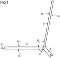
- the holding device 2 comprises a support element 9, a support element 11, a fastening element 6 and an adjusting element 14.
- the support element 9 and the support element 11 can be pivoted about a pivot axis A.
- Support element 9 and support element 11 can be designed as plate-shaped elements.
- the pivot axis A is horizontal when installed.
- the angle ⁇ is defined between a load bearing side 34 of the support element 9, which is directed away from the seat surface of the vehicle seat when installed, and an inner side 30 of the support element 11, which is directed away from the backrest of the vehicle when installed.
- the support element 9 When installed, the support element 9 lies at least partially with the support side 36 on the seat surface of the vehicle seat, a support surface 32 of the support element 11 is at least partially supported against a backrest of the vehicle seat.
- the fastening element 6 is connected in the region of the pivot axis of the support element 11 and the bearing element 9 to at least one of the two elements in a fixed or pivotable manner.
- support means (not shown) are provided.
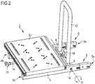
- FIGS 2 to 5 show views of a holding device 2 according to the invention in a second embodiment.
- the holding device 2 comprises two arms 4, 5 which extend parallel to one another.
- the arms 4, 5 each have a first end 4a, 5a and a second end 4b, 5b.
- a fastening element 6 is arranged on each of the arms 4, 5 at the first end 4a, 5a.
- the fastener 6 is here an Isofix locking device.
- a triggering means 26 (not shown here) can be present to actuate the Isofix locking device be.
- the fastening element 6 is rigidly connected to the arm 4 and the arm 5, respectively.
- the arms 4 and 5 are designed as a square profile.
- Each of the arms 4, 5 has a bearing 16 in which one end of a connecting element 8 engages.
- the bearing 16 and thus also the connecting element 8 is arranged in the region of the first ends 4a, 5a of the arms 4, 5.
- the connecting element 8 can be a square profile with cylindrical end regions.
- a bracket 12 is arranged on the connecting element 8 .
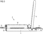
- the bracket 12 extends in a U-shape from the connecting element 8 and is designed here as a round tube. How out 3 As can be seen, the arms 4, 5 and the bracket 12 extend at an angle ⁇ to one another. The angle ⁇ can be adjusted by an adjusting element 14 .
- a support element 10 is arranged on the arms 4, 5 .
- the support member 10 extends from the second ends of the arms 4b, 5b to the connecting member and is fixedly connected to the arms 4,5.
- the support element 10 can, as in 4 shown having through holes 20 .
- a load can be attached to the support element 10 .
- the support element 10 When installed, the support element 10 preferably has a horizontal surface on the load receiving side 34 .
- an adjusting element 14 is arranged in the embodiment shown in such a way that an operating element 24 is arranged between the second ends of the arms 4b, 5b and the adjusting element 14 is guided by a guide element 22, which in figure 5 is shown, is performed.
- the guide element 22 expediently comprises a thread, so that an adjusting element 14 designed as a threaded spindle can be adjusted in its longitudinal position.
- the adjusting element 14 extends up to a projection 18 which is arranged on the connecting element 8 .
- Projection 18 and bracket 12 are preferably arranged in one plane and extend away from the connecting element 8 in substantially the same direction.
- FIG. 6 shows schematically the installation of the holding device 2 according to the invention on a vehicle seat 100 with a backrest 102 and a seat cushion 104.
- Isofix brackets 110 are typically arranged as vehicle-side brackets.
- the holding device 2 is locked with the fastening device 6, in particular the Isofix locking devices, with the Isofix brackets 110 of a seat.
- the arms 4, 5 of the holding device 2 are in the installed state at least in the region of the second ends 4b, 5b of the arms 4, 5, ie with the support side 36 of the support element 9 on the seat cushion.
- a full-surface support or the underlaying of a wedge cushion are possible in configurations.
- the bracket 12 is aligned as a support element 11 by means of the operating element 24 of the adjusting element 14 at such an angle ⁇ to the arms that the bracket 12 and the arms 4, 5 are spread apart against the seat backrest 102 and seat cushion 104 so that rotation of the holding device and /or a movement with a horizontal component is prevented.
- the angle ⁇ is greater than an angle ⁇ between the seat surface 104 and the seat back 102.
- a load 120 fixed on the holding device 2, e.g. a measuring device, can be held securely in position by the holding device 2.
- the holding device 2 according to the invention is easy to use.
- the support element 9 is formed by two arms 4, 5 and two transverse bars 28 running perpendicularly to the arms 4, 5.
- the transverse bars 28 are formed here, for example, by a strut profile with grooves on the outside.
- the cross members 28 have a load bearing side 34 which is at an angle ⁇ to the extension direction of the arms 4, 5, or the support side 36 run. The angle ⁇ is about 5° in the example shown.
- feet can be provided in the area of the bracket 12, so that the holding device 2 also provides a horizontal support surface along the upper side of the transverse bars 28 when the bracket 12 is folded away from the support element 9.
- the adjusting element 14 is provided with a knurled nut as the operating element 24 .
- the actuating element 14 is guided through openings in the transverse bars 28 .
- the fastening devices 6, in particular Isofix latching devices, are fastened to the first ends of the arms 4a, 5a, with the bore for fastening the fastening device 6 to the arms 4, 5 also serving as a bearing 16 for the connecting element 8.
- Through the arms 4, 5 are to the second end of the arms 4b, 5b triggering means 26 out here in the form of loops for the fastening devices, so that the fastening device 6 can be easily detached from the vehicle-side bracket.
Landscapes
- Engineering & Computer Science (AREA)
- Mechanical Engineering (AREA)
- Health & Medical Sciences (AREA)
- Child & Adolescent Psychology (AREA)
- General Health & Medical Sciences (AREA)
- Aviation & Aerospace Engineering (AREA)
- Transportation (AREA)
- Seats For Vehicles (AREA)
- Forklifts And Lifting Vehicles (AREA)
Description
- Die Erfindung betrifft eine Haltevorrichtung für eine Last auf einem Fahrzeugsitz, insbesondere betrifft die Erfindung eine Halterung zur Befestigung mittels Isofix.
- Aus dem Stand der Technik ist eine Haltevorrichtung für Messgeräte bekannt, welche mittels Isofix befestigt wird. Die bekannte Halterung weist zwei Befestigungsvorrichtungen auf, an denen ein erstes Bügelelement befestigt ist, welches zur Abstützung gegen eine Lehne des Sitzes geeignet ist. Mit dem Bügelelement ist ein Tragelement schwenkbar verbunden. Der Winkel zwischen Bügelelement und Klemmelement kann mittels zweier Klemmen fixiert werden. Eine ausreichende Fixierung des Winkels ist von der aufgewendeten Kraft des Nutzers abhängig. Auf einer gegenüberliegenden Seite des Tragelements ist ein Stützelement auf einer zum Sitzkissen gerichteten Seite angeordnet, so dass das Tragelement im eingebauten Zustand mit dem Stützelement auf dem Sitzkissen des Fahrzeugsitzes aufliegt. Das Tragelement ist mit einem weiteren Bügelelement verbunden, welches auf einer dem Bügelelement gegenüberliegenden Seite angeordnet ist und mit dem Tragelement schwenkbar verbunden ist. Ein Winkel zwischen zweitem Bügelelement und Tragelement kann mittels zweier Klemmen fixiert werden. Das zweite Bügelelement dient dazu, die Haltevorrichtung gegen eine Vorderseite des Fahrzeugsitzes zu klemmen. Die bekannte Haltevorrichtung bietet nur einen eingeschränkten Bedienkomfort.
- Bei einer weiteren bekannten Haltevorrichtung sind sowohl die Befestigungsvorrichtungen als auch das Bügelelement schwenkbar mit dem Tragelement verbunden.
- Bei weiteren bekannten Haltevorrichtungen kann auch die Last dazu verwendet werden, ein Verkippen der Haltevorrichtung um eine Horizontalachse zu beschränken. Dieses schränkt das Einsatzgebiet der Haltevorrichtung ein, da nur Lasten einer vorgegebenen Geometrie geeignet sind, auf dieser Haltevorrichtung befestigt zu werden. Alternativ können manche Haltevorrichtungen zusätzlich durch Gurte, z.B. den Sicherheitsgurt befestigt werden. Auch diese Haltevorrichtungen bieten nur einen eingeschränkten Bedienkomfort.
- Die
US 2005/0253431 A1 betrifft ein Kinderrückhaltesystem. Das Dokument offenbart Haltevorrichtung für eine Last auf einem Fahrzeugsitz umfassend - ein Auflageelement zum Fixieren einer Last,
- ein Stützelement, welches mit dem Auflageelement schwenkbar verbunden ist,
- zumindest eine Befestigungsvorrichtung zum Eingreifen in einen Haltebügel, welche mit dem Stützelement verbunden ist, und
- ein Stellelement,
- Die
DE 20 2015 100 327 U1 betrifft eine Aufnahmevorrichtung zur Anordnung in einem Kraftfahrzeug. Das Dokument offenbart eine klemmende Fixierung eines Winkels zwischen einem Auflageelement und einem Stützelement. Die D2 gibt keinen Hinweis, dass das Stellelement ausschließlich eine Verringerung des Winkels α beschränkt, und somit im ausgebauten Zustand der Haltevorrichtung das Stützelement vom Auflageelement wegschwenkbar ist, ohne das Stellelement zu verändern. - Die
GB 2524309 A - Die
DE 10 2006 023 948 A1 betrifft ein Transportbehältersicherungssystem. Das Sicherungssystem weist ein Auflageelement und eine damit schwenkbar verbundene Befestigungsvorrichtung zum Eingreifen in einen Haltebügel auf. Die bekannten Haltevorrichtungen sind kompliziert in der Handhabung und weisen nur einen geringen Widerstand gegen ein Verkippen um eine Horizontalachse in einem eingebauten Zustand auf. - Aufgabe der Erfindung ist es, die Nachteile nach dem Stand der Technik zu beseitigen. Insbesondere soll eine einfache Haltevorrichtung angegeben werden, die einen großen Widerstand gegen eine Vertikalbewegung der Haltevorrichtung aufweist und komfortabel zu bedienen ist.
- Die Aufgabe der Erfindung wird durch den Gegenstand des Anspruch 1 gelöst. Zweckmäßige Ausgestaltungen ergeben sich aus den abhängigen Ansprüchen.
- Die erfindungsgemäße Haltevorrichtung für eine Last auf einem Fahrzeugsitz umfasst
- ein Auflageelement zum Fixieren einer Last,
- ein Stützelement, welches mit dem Auflageelement schwenkbar verbunden ist,
- zumindest eine Befestigungsvorrichtung zum Eingreifen in einen Haltebügel, welche mit dem Stützelement und/oder dem Auflageelement verbunden ist, und
- ein Stellelement,
- Das Auflageelement ist dafür vorgesehen, mit einer Auflageseite auf einer Sitzfläche eines Fahrzeugsitzes zumindest teilweise aufzuliegen und auf einer der Auflageseite gegenüberliegenden Lastaufnahmeseite eine Last zu fixieren. Das Auflageelement kann ein flächiges Element sein. Das Stützelement ist dafür vorgesehen, die Haltevorrichtung mit einer Stützseite gegen eine Sitzlehne des Fahrzeugsitzes abzustützen. Auflageelement und Stützelement sind schwenkbar miteinander verbunden, wobei eine Schwenkachse ausgebildet ist. Die Schwenkachse ist zweckmäßigerweise im eingebauten Zustand der Haltevorrichtung eine Horizontalachse.
- Mit dem Auflageelement und/oder dem Stützelement ist eine Befestigungsvorrichtung starr oder schwenkbar verbunden. Das Befestigungselement umfasst zweckmäßigerweise eine Klammer und/oder ein Rastelement. Das Befestigungselement ist so angeordnet, dass es zum Eingreifen in einen Haltebügel der am Fahrzeugsitz, insbesondere im Bereich der Stoßkante zwischen Sitzfläche und Sitzlehne, angeordnet ist, geeignet ist. Zweckmäßigerweise ist somit das Befestigungselement an der Schwenkachse, in einer sich vom Auflageelement zur Schwenkachse erstreckenden Richtung mit dem Auflageelement verbunden oder in einer sich vom Stützelement zur Schwenkachse erstreckenden zweiten Richtung mit dem Stützelement verbunden. In einer Ausgestaltung, in der die Haltevorrichtung nur eine Befestigungsvorrichtung umfasst, sind zweckmäßigerweise auf beiden Seiten der Befestigungsvorrichtung Stützmittel zum Abstützen der Befestigungsvorrichtung gegen ein Verdrehen der Haltevorrichtung um eine Vertikalachse vorgesehen. In einer Ausgestaltung mit mehr als einer Befestigungsvorrichtung sind die Stützmittel entbehrlich.
- Das Stellelement ist dazu geeignet, Stützelement und Auflageelement um die Schwenkachse zu verschwenken und so einen Winkel α einzustellen. Der Winkel α ist insbesondere ein minimaler Winkel. Der Winkel α ist zwischen der Lastaufnahmeseite des Auflageelements und einer der Stützseite gegenüberliegenden Innenseite des Stützelements definiert. Der Winkel α ist im eingebauten Zustand der Haltevorrichtung gleich oder größer einem Winkel β, der zwischen Sitzfläche und Sitzlehne des Fahrzeugsitzes definiert ist. Das Stellelement ist insbesondere so ausgelegt, dass der Winkel α mit geringem Kraftaufwand eingestellt werden kann und somit die Funktion der Haltevorrichtung unabhängig von einer aufgebrachten Klemmkraft ist.
- Der Vorteil der erfindungsgemäßen Haltevorrichtung ist, dass die Haltevorrichtung auch gegen Drehbewegungen um eine horizontale Achse bzw. gegen vertikale Bewegungen gesichert ist. Die Haltevorrichtung ist einfach aufgebaut und bietet einen guten Bedienkomfort.
- In einem nicht-eingebauten Zustand kann das Stützelement von dem Auflageelement weg geschwenkt werden, so dass die Haltevorrichtung platzsparend verstaut werden kann. Gemäß der Erfindung ist die Haltevorrichtung so ausgestaltet, dass das Stellelement ausschließlich eine Verringerung des Winkels α beschränkt, und somit im ausgebauten Zustand der Haltevorrichtung das Stützelement vom Auflageelement weggeschwenkt werden kann, ohne das Stellelement zu verändern. Das Auflageelement und/oder Stützelement können auf einer von der Schwenkachse abgewandten Seite einen Griff aufweisen, um die Haltevorrichtung alleine oder mit der Last zu tragen.
- In Ausgestaltung ist der Haltebügel ein fahrzeugseitiger Isofix-Bügel und die Befestigungsvorrichtung eine Isofix-Rastvorrichtung. Isofix ist ein bekanntes Befestigungssystem für Kindersitze in Automobilen und ist nach der Norm ISO 13216 standardisiert. Bei dem fahrzeugseitigen Isofix Bügel kann es sich sowohl um einen originär mit dem Fahrzeugsitz verbundene Isofix-Bügel handeln als auch um einen Nachrüstsatz, der insbesondere lösbar mit dem Fahrzeugsitz verbunden ist.
- Zweckmäßigerweise umfasst die Haltevorrichtung genau zwei Befestigungsvorrichtungen, insbesondere Isofix-Rastvorrichtungen.
- In einer Ausgestaltung umfasst das Auflageelement zwei Arme mit jeweils einem ersten und einem zweiten Ende, welche vorzugsweise jeweils an einem ersten Ende eine Befestigungsvorrichtung zum Eingreifen in einen Haltebügel aufweisen, und ein mit beiden Armen im Bereich der zweiten Enden verbundenes Tragelement.
- Die beiden Arme erstrecken sich im Wesentlichen parallel zueinander. An einem ersten Ende weisen beide Arme ein Befestigungselement auf. Die Arme sind im Bereich des Befestigungselements so voneinander beabstandet, dass sie in den fahrzeugseitig vorgesehenen Haltebügel eingreifen können. Die Arme sind zweckmäßigerweise weiterhin geeignet, als Auflage auf einem Sitzkissen des Fahrzeugsitzes zu dienen. Insbesondere liegen die Arme im Bereich der zweiten Enden zumindest teilweise im eingebauten Zustand auf dem Sitzkissen des Fahrzeugsitzes auf.
- Der Abstand der beiden Arme voneinander wird durch ein Verbindungselement sowie das Tragelement fixiert. Zweckmäßigerweise sind die Arme linear ausgestaltet und verlaufen parallel zueinander.
- Das Tragelement weist insbesondere eine Aufnahme für eine Last und/oder eine Auflagefläche zum Anordnen einer Last, beispielsweise einem Messgerät, auf. Diese Auflagefläche auf der Lastaufnahmeseite kann einen fixen oder einstellbaren Winkel γ zur Erstreckungsrichtung der Arme d.h. der Auflageseite des Auflageelements bilden.
- Mit dem Tragelement ist ein Bügel z.B. in Form eines U-Bügels verbunden, welcher mit den Armen einen Winkel bildet. Insbesondere kann ein minimaler Winkel, z.B. 90° eingestellt werden. Das Verbindungselement ist insbesondere zwischen dem Tragelement und den Befestigungselementen angeordnet.
- In einer Ausgestaltung weisen die Arme jeweils ein Lager auf, um das Verbindungselement drehbar zu lagern. Ein solches Lager ist zweckmäßigerweise auf sich gegenüberliegenden Seiten der Arme in einem gleichen Abstand zu den ersten Enden angeordnet. Es kann sich z.B. um ein Sackloch oder Durchgangsloch zur Aufnahme eines zylinderförmigen Abschnittes des Verbindungselements handeln.
- Zweckmäßigerweise weist das Verbindungselement weiterhin einen Vorsprung auf, welcher durch Druck durch das Stellelement auf einen gewünschten Winkel α eingestellt werden kann. Vorzugsweise ist das Stellelement eine Gewindespindel. Eine entsprechende Gewindemutter ist zweckmäßigerweise mit dem Auflageelement verbunden. Eine solche Gewindespindel kann in einer einfachen Ausführung manuell durch eine Schraubbewegung betätigt werden. Alternativ kann es sich aber auch um eine motorisiert angetriebene Spindel handeln. Weiter alternativ kann es sich bei dem Stellelement aber beispielsweise auch um einen Klinkentrieb oder Raststange handeln.
- Das Stellelement kann ein Bedienelement aufweisen, welches auf einer einer Schwenkachse A zwischen Stützelement und Auflageelement abgewandten Seite des Auflageelements angeordnet ist.
- Bei dem Bedienelement kann es sich insbesondere um eine Flügelmutter, eine Rändelmutter, einen Zylindergriff, einen Kreuzgriff oder einen Sterngriff handeln. In dieser Ausführungsform ist das Stellelement zweckmäßigerweise in einer Führung unter dem Tragelement durchgeführt. Die Führung kann auch die Funktion eines Berührschutzes übernehmen.
- In einer weiteren Ausgestaltung ist das Tragelement, aus einem abgekanteten oder umgeformten Blech hergestellt oder aus zumindest zwei Querholmen gebildet. Zweckmäßigerweise weist das Auflageelement, insbesondere das Tragelement, Befestigungselemente und/oder Durchgangslöcher und/oder Nuten auf. Die Querholme können Nuten aufweisen, insbesondere können sie aus Strebenprofilen gebildet sein. Dabei kann es sich beispielsweise auch um Möglichkeiten zu einer Gurtdurchführung oder zur Befestigung weiterer Rastmittel handeln.
- In Ausgestaltung sind die Arme und/oder das Verbindungselement aus einem Vierkantprofil hergestellt.
- Der Bügel weist in einer Ausgestaltung eine U-Form oder V-Form auf. Alternativ oder zusätzlich kann das Stützelement ein plattenförmiges Element umfassen. Z.B. kann eine Öffnung des Bügels zumindest teilweise mit einem plattenförmigen Element geschlossen sein. Die Form des Bügels kann an eine Form der Sitzlehne des Fahrzeuges angepasst sein, um einen breiten Stützbereich aufzuweisen. Ein breiter Stützbereich erhöht zum einen einen Widerstand gegen Bewegungen mit einer Vertikalkomponente, zum anderen wird ein Bezug einer Rückenlehne des Fahrzeuges geschont. Ein Verschluss des Bügels mit einem plattenförmigen Element kann ebenfalls zum Schonen eines Bezugs einer Rückenlehne des Fahrzeuges dienen.
- Die Erfindung wird nachstehend auch hinsichtlich weiterer Merkmale und Vorteile anhand der Beschreibung von Ausführungsbeispielen und unter Bezugnahme auf die beiliegenden Zeichnungen näher erläutert. Es zeigen jeweils in einer schematischen Prinzipskizze:
-
Fig. 1 : schematische Darstellung der Haltevorrichtung in einer ersten Ausgestaltung -
Fig. 2 : perspektivische Ansicht der Haltevorrichtung in einer zweiten Ausgestaltung -
Fig. 3 : Seitenansicht der Haltevorrichtung nach der zweiten Ausgestaltung, -
Fig. 4 : Draufsicht der Haltevorrichtung nach der zweiten Ausgestaltung, -
Fig. 5 : Unteransicht der Haltevorrichtung nach der zweiten Ausgestaltung, -
Fig. 6 : Prinzipskizze der Montage einer Haltevorrichtung auf einem Fahrzeugsitz, -
Fig. 7 : perspektivische Ansicht der Haltevorrichtung in einer dritten Ausgestaltung, und -
Fig. 8 : Seitenansicht der Haltevorrichtung nach der dritten Ausgestaltung. -
Fig. 1 zeigt eine schematische Ansicht der erfindungsgemäßen Haltevorrichtung 2 in einer ersten Ausgestaltung. Die Haltevorrichtung 2 umfasst ein Auflageelement 9, ein Stützelement 11, ein Befestigungselement 6 und ein Stellelement 14. Das Auflageelement 9 und das Stützelement 11 sind um eine Schwenkachse A schwenkbar. Auflageelement 9 und Stützelement 11 können als plattenförmige Elemente ausgestaltet sein. Die Schwenkachse A ist im eingebauten Zustand horizontal. Zwischen einer Lastaufnahmeseite 34 des Auflageelements 9, die im eingebauten Zustand von der Sitzfläche des Fahrzeugsitzes weg gerichtet ist, zu einer Innenseite 30 des Stützelements 11, die im eingebauten Zustand von der Sitzlehne des Fahrzeuges weggerichtet ist, ist der Winkel α definiert. Im eingebauten Zustand liegt das Auflageelement 9 zumindest teilweise mit der Auflageseite 36 auf der Sitzfläche des Fahrzeugsitzes auf, eine Stützfläche 32 des Stützelements 11 ist zumindest teilweise gegen eine Sitzlehne des Fahrzeugsitzes abgestützt. In der gezeigten Ausgestaltung ist das Befestigungselement 6 im Bereich der Schwenkachse von Stützelement 11 und Auflageelement 9 mit zumindest einem der beiden Elemente fest oder schwenkbar verbunden. Zur Verhinderung eines Verkippens der Haltevorrichtung um eine vertikale Achse im eingebauten Zustand sind nicht dargestellte Stützmittel vorgesehen. -
Fig. 2 bis 5 zeigen Ansichten einer erfindungsgemäßen Haltevorrichtung 2 in einer zweiten Ausgestaltung. Die Haltevorrichtung 2 umfasst zwei Arme 4, 5, welche sich parallel zueinander erstrecken. Die Arme 4, 5 weisen jeweils ein erstes Ende 4a, 5a und ein zweites Ende 4b, 5b auf. Am ersten Ende 4a, 5a ist an jedem der Arme 4, 5 ein Befestigungselement 6 angeordnet. Das Befestigungselement 6 ist hier eine Isofix-Rastvorrichtung. Zur Betätigung der Isofix-Rastvorrichtung kann ein hier nicht dargestelltes Auslösemittel 26 vorhanden sein. Das Befestigungselement 6 ist starr mit dem Arm 4 bzw. dem Arm 5 verbunden. Die Arme 4 und 5 sind als Vierkantprofil ausgebildet. Jeder der Arme 4, 5 weist ein Lager 16 auf, in welches jeweils ein Ende eines Verbindungselements 8 eingreift. Das Lager 16 und somit auch das Verbindungselement 8 ist im Bereich der ersten Enden 4a, 5a der Arme 4, 5 angeordnet. Das Verbindungselement 8 kann -wie hier dargestellt- ein Vierkantprofil mit zylindrischen Endbereichen sein. Auf dem Verbindungselement 8 ist ein Bügel 12 angeordnet. Der Bügel 12 erstreckt sich U-förmig von dem Verbindungselement 8 und ist hier als Rundrohr ausgeführt. Wie ausFig. 3 ersichtlich, erstrecken sich die Arme 4, 5 und der Bügel 12 in einem Winkel α zueinander. Der Winkel α kann durch ein Stellelement 14 eingestellt werden. - Auf den Armen 4, 5 ist ein Tragelement 10 angeordnet. Das Tragelement 10 erstreckt sich von den zweiten Enden der Arme 4b, 5b zum Verbindungselement und ist mit den Armen 4, 5 fest verbunden. Das Tragelement 10 kann, wie in
Fig. 4 gezeigt, Durchgangslöcher 20 aufweisen. Auf dem Tragelement 10 kann eine Last befestigt werden. Das Tragelement 10 hat im eingebauten Zustand auf der Lastaufnahmeseite 34 vorzugsweise eine horizontale Oberfläche. - Unter dem Tragelement 10 ist ein Stellelement 14 in der gezeigten Ausführung so angeordnet, dass ein Bedienelement 24 zwischen den zweiten Enden der Arme 4b, 5b angeordnet ist und das Stellelement 14 durch ein Führungselement 22, welches in
Fig. 5 dargestellt ist, geführt wird. Das Führungselement 22 umfasst zweckmäßigerweise ein Gewinde, so dass ein als Gewindespindel ausgeführtes Stellelement 14 in seiner Längsposition verstellt werden kann. Das Stellelement 14 erstreckt sich bis zu einem Vorsprung 18, der auf dem Verbindungselement 8 angeordnet ist. Vorsprung 18 und Bügel 12 sind vorzugsweise in einer Ebene angeordnet und erstrecken sich im Wesentlichen in die gleiche Richtung vom Verbindungselement 8 weg. - Durch Drehen des als Gewindespindel ausgeführten Stellelements 14 wird ein Druck auf den Vorsprung 18 ausgeübt und der Winkel α (minimale Winkel o) des Bügels wird eingestellt.
-
Fig. 6 zeigt schematisch den Einbau der erfindungsgemäßen Haltevorrichtung 2 auf einem Fahrzeugsitz 100 mit einer Rückenlehne 102 und einem Sitzkissen 104. Im Stoßbereich zwischen Sitzkissen 104 und Rückenlehne 102 sind typischerweise Isofix-Bügel 110 als fahrzeugseitige Haltebügel angeordnet. Die Haltevorrichtung 2 wird mit der Befestigungsvorrichtung 6, insbesondere den Isofix-Rastvorrichtungen, mit den Isofix-Bügeln 110 eines Sitzes verrastet. Die Arme 4, 5 der Haltevorrichtung 2 liegen im eingebauten Zustand zumindest im Bereich der zweiten Enden 4b, 5b der Arme 4, 5, d.h. mit der Auflageseite 36 des Auflageelements 9 auf dem Sitzkissen auf. Eine vollflächige Auflage bzw. das Unterlegen eines Keilkissens sind in Ausgestaltungen möglich. Der Bügel 12 wird als Stützelement 11 mittels dem Bedienelement 24 des Stellelements 14 in einem solchen Winkel α zu den Armen ausgerichtet, dass der Bügel 12 und die Arme 4, 5 so gegen Sitzlehne 102 und Sitzkissen 104 gespreizt wird, dass eine Drehung der Haltevorrichtung und/oder eine Bewegung mit einer horizontalen Komponente verhindert wird. In der dargestellten Ausgestaltung ist der Winkel α größer als ein Winkel β zwischen der Sitzfläche 104 und der Sitzlehne 102. - Eine auf der Haltevorrichtung 2 fixierte Last 120, z.B. ein Messgerät, kann durch die Haltevorrichtung 2 sicher in Position gehalten werden. Die erfindungsgemäße Haltevorrichtung 2 ist einfach zu bedienen.
-
Fig. 7 und8 zeigen eine dritte Ausgestaltung der Haltevorrichtung 2. Die dritte Ausgestaltung ähnelt der zweiten Ausgestaltung, so dass hier die Abweichungen in Bezug auf dieFig. 7 und8 erläutert werden. In dieser dritten Ausgestaltung ist das Auflageelement 9 durch zwei Arme 4, 5 und zwei senkrecht zu den Armen 4, 5 verlaufende Querholme 28 gebildet. Die Querholme 28 sind hier zum Beispiel durch ein Streben-Profil mit außenliegenden Nuten gebildet. Die Querholme 28 weisen eine Lastaufnahmeseite 34 auf, die in einem Winkel γ zur Erstreckungsrichtung der Arme 4, 5, bzw. der Auflageseite 36 verlaufen. Der Winkel γ ist im gezeigten Beispiel etwa 5°. Um ein Abstellen einer nicht montierten Haltevorrichtung 2 zu erleichtern, können im Bereich des Bügels 12 Füße vorgesehen sein, so dass die Haltevorrichtung 2, wenn der Bügel 12 von dem Auflageelement 9 weggeklappt ist, entlang der Oberseite der Querholme 28 auch eine horizontale Auflagefläche bereitstellt. - Das Stellelement 14 ist mit einer Rändelmutter als Bedienelement 24 versehen. Das Stellelement 14 ist durch Durchbrüche in den Querholmen 28 geführt. Die Befestigungsvorrichtungen 6, insbesondere Isofix-Rastvorrichtungen, sind an den ersten Enden der Arme 4a, 5a befestigt, wobei jeweils die Bohrung für die Befestigung der Befestigungsvorrichtung 6 an den Armen 4, 5 gleichzeitig als Lager 16 für das Verbindungselement 8 dient. Durch die Arme 4, 5 sind zum zweiten Ende der Arme 4b, 5b Auslösemittel 26, hier in Form von Schlaufen für die Befestigungsvorrichtungen geführt, so dass die Befestigungsvorrichtung 6 komfortabel vom fahrzeugseitigen Haltebügel gelöst werden kann.
-
- 2
- Haltevorrichtung
- 4
- Arm
- 4a
- erstes Ende
- 4b
- zweites Ende
- 5
- Arm
- 5a
- erstes Ende
- 5b
- zweites Ende
- 6
- Befestigungsvorrichtung
- 8
- Verbindungselement
- 9
- Auflageelement
- 10
- Tragelement
- 11
- Stützelement
- 12
- Bügel
- 14
- Stellelement
- 16
- Lager
- 18
- Vorsprung
- 20
- Durchgangsloch
- 22
- Führungselement
- 24
- Bedienelement
- 26
- Auslösemittel
- 28
- Querholm
- 30
- Innenseite
- 32
- Stützseite
- 34
- Lastaufnahmeseite
- 36
- Auflageseite
- 100
- Fahrzeugsitz
- 102
- Sitzlehne
- 104
- Sitzkissen
- 110
- Isofix-Bügel
- 120
- Last
- α
- Winkel
- β
- Winkel
- γ
- Winkel
- A
- Schwenkachse
Claims (13)
- Haltevorrichtung (2) für eine Last (120) auf einem Fahrzeugsitz (100) umfassend- ein Auflageelement (9) zum Fixieren einer Last (120),- ein Stützelement (11), welches mit dem Auflageelement (9) schwenkbar verbunden ist,- zumindest eine Befestigungsvorrichtung (6) zum Eingreifen in einen Haltebügel, welche mit dem Stützelement (11) und/oder dem Auflageelement (9) verbunden ist, und- ein Stellelement (14),wobei das Stellelement (14) geeignet ist, einen Winkel α so zwischen dem Stützelement (11) und dem Auflageelement (9) einzustellen, dass im eingebauten Zustand das Auflageelement (9) gegen eine Sitzfläche (104) und das Stützelement (11) gegen eine Sitzlehne (102) des Fahrzeugsitzes (100) spreizbar sind und ein Verdrehen der Haltevorrichtung (2) um eine Horizontalachse und/oder eine Bewegung senkrecht zur Sitzfläche (104) verhindert wird,dadurch gekennzeichnet,dass das Stellelement ausschließlich eine Verringerung des Winkels α beschränkt, und somit im ausgebauten Zustand der Haltevorrichtung das Stützelement vom Auflageelement wegschwenkbar ist, ohne das Stellelement zu verändern.
- Haltevorrichtung (2) nach Anspruch 1, wobei die Befestigungsvorrichtung (6) eine Isofix-Rastvorrichtung ist, für einen fahrzeugseitigen Isofix-Bügel (110).
- Haltevorrichtung (2) nach Anspruch 1 oder 2, wobei die Haltevorrichtung genau zwei Befestigungsvorrichtungen (6) umfasst.
- Haltevorrichtung (2) nach Anspruch 3, wobei das Auflageelement (9) zwei Arme (4, 5) mit jeweils einem ersten (4a, 5a) und einem zweiten Ende (4b, 5b), welche vorzugsweise jeweils an dem ersten Ende (4a, 5a) eine Befestigungsvorrichtung (6) zum Eingreifen in den Haltebügel aufweisen, und ein mit beiden Armen (4, 5) im Bereich der zweiten Enden (4b, 5b) verbundenes Tragelement (10) umfasst.
- Haltevorrichtung (2) nach Anspruch 4, wobei die Arme (4, 5) jeweils ein Lager (16) aufweisen, um das Stützelement (11) drehbar zu lagern.
- Haltevorrichtung (2) nach einem der vorhergehenden Ansprüche, wobei das Stützelement (11) ein Verbindungselement (8) und einen Bügel (12), insbesondere einen U-förmigen oder V-förmigen Bügel, umfasst.
- Haltevorrichtung (2) nach Anspruch 6, wobei das Verbindungselement (8) weiterhin einen Vorsprung (18) aufweist, welcher durch Druck durch das Stellelement (14) auf einen gewünschten Winkel α eingestellt werden kann.
- Haltevorrichtung (2) nach einem der vorhergehenden Ansprüche, wobei das Stellelement (14) eine Gewindespindel ist.
- Haltevorrichtung (2) nach einem der vorhergehenden Ansprüche, wobei das Stellelement (14) ein Bedienelement (24) aufweist, welches auf einer einer Schwenkachse A zwischen Stützelement (11) und Auflageelement (9) abgewandten Seite des Auflageelements (9) angeordnet ist.
- Haltevorrichtung (2) nach einem der Ansprüche 4 bis 9, wobei das Tragelement (10) aus einem abgekanteten oder umgeformten Blech hergestellt ist oder aus zumindest zwei Querholmen (28), vorzugsweise hergestellt aus Strebenprofilen, gebildet ist.
- Haltevorrichtung (2) nach einem der vorhergehenden Ansprüche, wobei das Auflageelement (9), insbesondere das Tragelement (10), zumindest ein Befestigungselement und/oder Durchgangslöcher (20) und/oder Nuten aufweist.
- Haltevorrichtung (2) nach den Ansprüchen 4 und/oder 6, wobei die Arme (4, 5) und/oder das Verbindungselement (8) aus einem Vierkantprofil hergestellt sind.
- Haltevorrichtung (2) nach einem der vorhergehenden Ansprüche, wobei das Stützelement (11) ein plattenförmiges Element umfasst.
Applications Claiming Priority (2)
| Application Number | Priority Date | Filing Date | Title |
|---|---|---|---|
| DE102018105535.8A DE102018105535A1 (de) | 2018-03-09 | 2018-03-09 | Haltevorrichtung für eine Last auf einem Fahrzeugsitz |
| PCT/EP2019/055346 WO2019170618A1 (de) | 2018-03-09 | 2019-03-04 | Haltevorrichtung für eine last auf einem fahrzeugsitz |
Publications (2)
| Publication Number | Publication Date |
|---|---|
| EP3762253A1 EP3762253A1 (de) | 2021-01-13 |
| EP3762253B1 true EP3762253B1 (de) | 2022-11-02 |
Family
ID=65686854
Family Applications (1)
| Application Number | Title | Priority Date | Filing Date |
|---|---|---|---|
| EP19709437.8A Active EP3762253B1 (de) | 2018-03-09 | 2019-03-04 | Haltevorrichtung für eine last auf einem fahrzeugsitz |
Country Status (4)
| Country | Link |
|---|---|
| EP (1) | EP3762253B1 (de) |
| DE (1) | DE102018105535A1 (de) |
| ES (1) | ES2937925T3 (de) |
| WO (1) | WO2019170618A1 (de) |
Cited By (1)
| Publication number | Priority date | Publication date | Assignee | Title |
|---|---|---|---|---|
| EP4674691A3 (de) * | 2024-07-01 | 2026-03-18 | SARP Feinmechanik GmbH | Transportsystem für betriebsbereite mess- und datensystem in kfz |
Families Citing this family (3)
| Publication number | Priority date | Publication date | Assignee | Title |
|---|---|---|---|---|
| DE102022107865B3 (de) | 2022-04-01 | 2023-07-20 | Dr. Ing. H.C. F. Porsche Aktiengesellschaft | Geräuschmesseinrichtung |
| DE102022108084B4 (de) | 2022-04-05 | 2023-10-12 | Dr. Ing. H.C. F. Porsche Aktiengesellschaft | Geräuschmesseinrichtung |
| US12583392B1 (en) * | 2023-12-06 | 2026-03-24 | David Reign Wilks, Jr. | Locakable ISOFIX connection device and method of securing an object to a vehicle seat |
Family Cites Families (8)
| Publication number | Priority date | Publication date | Assignee | Title |
|---|---|---|---|---|
| DE20212332U1 (de) * | 2001-10-19 | 2002-11-14 | Nüssel, Michael, 95509 Marktschorgast | Transportbox und Adapterplatte mit Isofixconnectoren |
| US20080303321A1 (en) * | 2004-05-08 | 2008-12-11 | Britax Excelsior Limited | Base for a Child Safety Support |
| US7338122B2 (en) * | 2004-05-17 | 2008-03-04 | Orbit Baby, Inc. | Modular child restraint system |
| DE102006023948B4 (de) * | 2006-05-17 | 2015-09-03 | Stefanie Schanen | Transportbehältersicherungssystem |
| DE202006008165U1 (de) * | 2006-05-17 | 2006-09-21 | Schanen, Stefanie | Transportbehältersicherungssystem |
| GB2524309B (en) * | 2014-03-20 | 2017-03-01 | Pain Phillip | Car seat base |
| DE202015100327U1 (de) * | 2015-01-23 | 2016-04-26 | Wolfgang Nickel | Aufnahmevorrichtung |
| DE102015113584A1 (de) * | 2015-08-17 | 2017-02-23 | Adolf Würth GmbH & Co. KG | Montageeinrichtung zum Montieren einer Adaptervorrichtung zum Befestigen von Aufnahmekörpern an einem Kraftfahrzeugsitz |
-
2018
- 2018-03-09 DE DE102018105535.8A patent/DE102018105535A1/de not_active Ceased
-
2019
- 2019-03-04 WO PCT/EP2019/055346 patent/WO2019170618A1/de not_active Ceased
- 2019-03-04 EP EP19709437.8A patent/EP3762253B1/de active Active
- 2019-03-04 ES ES19709437T patent/ES2937925T3/es active Active
Cited By (1)
| Publication number | Priority date | Publication date | Assignee | Title |
|---|---|---|---|---|
| EP4674691A3 (de) * | 2024-07-01 | 2026-03-18 | SARP Feinmechanik GmbH | Transportsystem für betriebsbereite mess- und datensystem in kfz |
Also Published As
| Publication number | Publication date |
|---|---|
| WO2019170618A1 (de) | 2019-09-12 |
| ES2937925T3 (es) | 2023-04-03 |
| DE102018105535A1 (de) | 2019-09-12 |
| EP3762253A1 (de) | 2021-01-13 |
Similar Documents
| Publication | Publication Date | Title |
|---|---|---|
| EP3762253B1 (de) | Haltevorrichtung für eine last auf einem fahrzeugsitz | |
| DE102010031048B4 (de) | Sitzanordnung mit einer Führungshülse | |
| DE102012004342B4 (de) | Ausstattungsteil für einen Fahrzeugsitz und Fahrzeugsitz | |
| EP4144597A1 (de) | Fahrzeugsitzstruktur sowie verfahren zur montage einer fahrzeugsitzstruktur | |
| DE102016108858A1 (de) | Vorrichtung zur Anbringung einer Sitzanordnung an einem Fahrzeug und Fahrzeug | |
| DE19918785C1 (de) | Beschlag für einen Fahrzeugsitz | |
| DE19812490A1 (de) | Einrichtung zur lösbaren Befestigung eines Sitzes, insbesondere Fahrzeugsitzes, an einer längsverlaufenden Schiene | |
| DE9318743U1 (de) | Sitzbank für Reisemobile, Transporter, etc. mit mindestens zwei Sitzteilen und mindestens zwei Rückenlehnenteilen sowie einer Einrichtung zur Aufnahme des oberen Punktes des Schultergurtes von mindestens einem Dreipunkt-Rückhaltesystem | |
| DE102005043333B4 (de) | Kraftfahrzeugsitz mit einem in der Höhe verstellbaren Sitzkissen und einem mit dem Sitzkissen verbundenen Befestigungspunkt für einen Sicherheitsgurt | |
| DE20218780U1 (de) | Vorrichtung zum Positionieren eines Gegenstandes | |
| DE202018101352U1 (de) | Haltevorrichtung für eine Last auf einem Fahrzeugsitz | |
| DE29703661U1 (de) | Vorrichtung zur Halterung eines Regenschirms an einer Tür eines Kraftfahrzeugs | |
| DE8534636U1 (de) | Vorrichtung zur Befestigung von Dachlasten | |
| EP3375659B1 (de) | Vorrichtung zur anordnung eines personenrückhaltesystems in einem fahrzeug | |
| DE102014202239B3 (de) | Fahrzeugsitz | |
| DE2729877A1 (de) | Vorrichtung zur befestigung mindestens eines gegenstandes innerhalb eines fahrgastraumes eines kraftfahrzeuges | |
| DE19906669C2 (de) | Vorrichtung zur Befestigung eines Fahrzeugsitzes | |
| DE1094608B (de) | Vorrichtung zum Verstellen der Rueckenlehne von Sitzen, insbesondere fuer Kraftfahrzeuge | |
| DE102020119851B4 (de) | Fahrzeugsitz sowie abstützvorrichtung für einen fahrzeugsitz | |
| DE19915315A1 (de) | Neigungsverstellvorrichtung für eine Fondsitzlehne | |
| DE102013221931B4 (de) | Beschlag und Fahrzeugsitz mit einem Beschlag | |
| DE20201327U1 (de) | Vorrichtung zum Verankern eines Sitzes an einem Fahrzeugboden | |
| DE102006000951B3 (de) | Manuell längsverstellbarer Kraftfahrzeugsitz | |
| CH442051A (de) | Armstütze für Kraftfahrzeuge | |
| DE3540577A1 (de) | Verriegelungseinrichtung fuer einen kraftfahrzeugsitz |
Legal Events
| Date | Code | Title | Description |
|---|---|---|---|
| STAA | Information on the status of an ep patent application or granted ep patent |
Free format text: STATUS: UNKNOWN |
|
| STAA | Information on the status of an ep patent application or granted ep patent |
Free format text: STATUS: THE INTERNATIONAL PUBLICATION HAS BEEN MADE |
|
| PUAI | Public reference made under article 153(3) epc to a published international application that has entered the european phase |
Free format text: ORIGINAL CODE: 0009012 |
|
| STAA | Information on the status of an ep patent application or granted ep patent |
Free format text: STATUS: REQUEST FOR EXAMINATION WAS MADE |
|
| 17P | Request for examination filed |
Effective date: 20200918 |
|
| AK | Designated contracting states |
Kind code of ref document: A1 Designated state(s): AL AT BE BG CH CY CZ DE DK EE ES FI FR GB GR HR HU IE IS IT LI LT LU LV MC MK MT NL NO PL PT RO RS SE SI SK SM TR |
|
| AX | Request for extension of the european patent |
Extension state: BA ME |
|
| DAV | Request for validation of the european patent (deleted) | ||
| DAX | Request for extension of the european patent (deleted) | ||
| GRAP | Despatch of communication of intention to grant a patent |
Free format text: ORIGINAL CODE: EPIDOSNIGR1 |
|
| STAA | Information on the status of an ep patent application or granted ep patent |
Free format text: STATUS: GRANT OF PATENT IS INTENDED |
|
| INTG | Intention to grant announced |
Effective date: 20220525 |
|
| GRAS | Grant fee paid |
Free format text: ORIGINAL CODE: EPIDOSNIGR3 |
|
| GRAA | (expected) grant |
Free format text: ORIGINAL CODE: 0009210 |
|
| STAA | Information on the status of an ep patent application or granted ep patent |
Free format text: STATUS: THE PATENT HAS BEEN GRANTED |
|
| AK | Designated contracting states |
Kind code of ref document: B1 Designated state(s): AL AT BE BG CH CY CZ DE DK EE ES FI FR GB GR HR HU IE IS IT LI LT LU LV MC MK MT NL NO PL PT RO RS SE SI SK SM TR |
|
| REG | Reference to a national code |
Ref country code: GB Ref legal event code: FG4D Free format text: NOT ENGLISH |
|
| REG | Reference to a national code |
Ref country code: CH Ref legal event code: EP Ref country code: AT Ref legal event code: REF Ref document number: 1528538 Country of ref document: AT Kind code of ref document: T Effective date: 20221115 |
|
| REG | Reference to a national code |
Ref country code: DE Ref legal event code: R096 Ref document number: 502019006128 Country of ref document: DE |
|
| REG | Reference to a national code |
Ref country code: IE Ref legal event code: FG4D Free format text: LANGUAGE OF EP DOCUMENT: GERMAN |
|
| REG | Reference to a national code |
Ref country code: LT Ref legal event code: MG9D |
|
| REG | Reference to a national code |
Ref country code: NL Ref legal event code: MP Effective date: 20221102 |
|
| REG | Reference to a national code |
Ref country code: ES Ref legal event code: FG2A Ref document number: 2937925 Country of ref document: ES Kind code of ref document: T3 Effective date: 20230403 |
|
| PG25 | Lapsed in a contracting state [announced via postgrant information from national office to epo] |
Ref country code: SE Free format text: LAPSE BECAUSE OF FAILURE TO SUBMIT A TRANSLATION OF THE DESCRIPTION OR TO PAY THE FEE WITHIN THE PRESCRIBED TIME-LIMIT Effective date: 20221102 Ref country code: PT Free format text: LAPSE BECAUSE OF FAILURE TO SUBMIT A TRANSLATION OF THE DESCRIPTION OR TO PAY THE FEE WITHIN THE PRESCRIBED TIME-LIMIT Effective date: 20230302 Ref country code: NO Free format text: LAPSE BECAUSE OF FAILURE TO SUBMIT A TRANSLATION OF THE DESCRIPTION OR TO PAY THE FEE WITHIN THE PRESCRIBED TIME-LIMIT Effective date: 20230202 Ref country code: LT Free format text: LAPSE BECAUSE OF FAILURE TO SUBMIT A TRANSLATION OF THE DESCRIPTION OR TO PAY THE FEE WITHIN THE PRESCRIBED TIME-LIMIT Effective date: 20221102 Ref country code: FI Free format text: LAPSE BECAUSE OF FAILURE TO SUBMIT A TRANSLATION OF THE DESCRIPTION OR TO PAY THE FEE WITHIN THE PRESCRIBED TIME-LIMIT Effective date: 20221102 |
|
| PG25 | Lapsed in a contracting state [announced via postgrant information from national office to epo] |
Ref country code: RS Free format text: LAPSE BECAUSE OF FAILURE TO SUBMIT A TRANSLATION OF THE DESCRIPTION OR TO PAY THE FEE WITHIN THE PRESCRIBED TIME-LIMIT Effective date: 20221102 Ref country code: PL Free format text: LAPSE BECAUSE OF FAILURE TO SUBMIT A TRANSLATION OF THE DESCRIPTION OR TO PAY THE FEE WITHIN THE PRESCRIBED TIME-LIMIT Effective date: 20221102 Ref country code: LV Free format text: LAPSE BECAUSE OF FAILURE TO SUBMIT A TRANSLATION OF THE DESCRIPTION OR TO PAY THE FEE WITHIN THE PRESCRIBED TIME-LIMIT Effective date: 20221102 Ref country code: IS Free format text: LAPSE BECAUSE OF FAILURE TO SUBMIT A TRANSLATION OF THE DESCRIPTION OR TO PAY THE FEE WITHIN THE PRESCRIBED TIME-LIMIT Effective date: 20230302 Ref country code: HR Free format text: LAPSE BECAUSE OF FAILURE TO SUBMIT A TRANSLATION OF THE DESCRIPTION OR TO PAY THE FEE WITHIN THE PRESCRIBED TIME-LIMIT Effective date: 20221102 Ref country code: GR Free format text: LAPSE BECAUSE OF FAILURE TO SUBMIT A TRANSLATION OF THE DESCRIPTION OR TO PAY THE FEE WITHIN THE PRESCRIBED TIME-LIMIT Effective date: 20230203 |
|
| PG25 | Lapsed in a contracting state [announced via postgrant information from national office to epo] |
Ref country code: NL Free format text: LAPSE BECAUSE OF FAILURE TO SUBMIT A TRANSLATION OF THE DESCRIPTION OR TO PAY THE FEE WITHIN THE PRESCRIBED TIME-LIMIT Effective date: 20221102 |
|
| PG25 | Lapsed in a contracting state [announced via postgrant information from national office to epo] |
Ref country code: SM Free format text: LAPSE BECAUSE OF FAILURE TO SUBMIT A TRANSLATION OF THE DESCRIPTION OR TO PAY THE FEE WITHIN THE PRESCRIBED TIME-LIMIT Effective date: 20221102 Ref country code: RO Free format text: LAPSE BECAUSE OF FAILURE TO SUBMIT A TRANSLATION OF THE DESCRIPTION OR TO PAY THE FEE WITHIN THE PRESCRIBED TIME-LIMIT Effective date: 20221102 Ref country code: EE Free format text: LAPSE BECAUSE OF FAILURE TO SUBMIT A TRANSLATION OF THE DESCRIPTION OR TO PAY THE FEE WITHIN THE PRESCRIBED TIME-LIMIT Effective date: 20221102 Ref country code: DK Free format text: LAPSE BECAUSE OF FAILURE TO SUBMIT A TRANSLATION OF THE DESCRIPTION OR TO PAY THE FEE WITHIN THE PRESCRIBED TIME-LIMIT Effective date: 20221102 Ref country code: CZ Free format text: LAPSE BECAUSE OF FAILURE TO SUBMIT A TRANSLATION OF THE DESCRIPTION OR TO PAY THE FEE WITHIN THE PRESCRIBED TIME-LIMIT Effective date: 20221102 |
|
| REG | Reference to a national code |
Ref country code: DE Ref legal event code: R097 Ref document number: 502019006128 Country of ref document: DE |
|
| PG25 | Lapsed in a contracting state [announced via postgrant information from national office to epo] |
Ref country code: SK Free format text: LAPSE BECAUSE OF FAILURE TO SUBMIT A TRANSLATION OF THE DESCRIPTION OR TO PAY THE FEE WITHIN THE PRESCRIBED TIME-LIMIT Effective date: 20221102 Ref country code: AL Free format text: LAPSE BECAUSE OF FAILURE TO SUBMIT A TRANSLATION OF THE DESCRIPTION OR TO PAY THE FEE WITHIN THE PRESCRIBED TIME-LIMIT Effective date: 20221102 |
|
| PLBE | No opposition filed within time limit |
Free format text: ORIGINAL CODE: 0009261 |
|
| STAA | Information on the status of an ep patent application or granted ep patent |
Free format text: STATUS: NO OPPOSITION FILED WITHIN TIME LIMIT |
|
| 26N | No opposition filed |
Effective date: 20230803 |
|
| PG25 | Lapsed in a contracting state [announced via postgrant information from national office to epo] |
Ref country code: MC Free format text: LAPSE BECAUSE OF FAILURE TO SUBMIT A TRANSLATION OF THE DESCRIPTION OR TO PAY THE FEE WITHIN THE PRESCRIBED TIME-LIMIT Effective date: 20221102 |
|
| PG25 | Lapsed in a contracting state [announced via postgrant information from national office to epo] |
Ref country code: SI Free format text: LAPSE BECAUSE OF FAILURE TO SUBMIT A TRANSLATION OF THE DESCRIPTION OR TO PAY THE FEE WITHIN THE PRESCRIBED TIME-LIMIT Effective date: 20221102 |
|
| REG | Reference to a national code |
Ref country code: BE Ref legal event code: MM Effective date: 20230331 |
|
| PG25 | Lapsed in a contracting state [announced via postgrant information from national office to epo] |
Ref country code: LU Free format text: LAPSE BECAUSE OF NON-PAYMENT OF DUE FEES Effective date: 20230304 |
|
| REG | Reference to a national code |
Ref country code: IE Ref legal event code: MM4A |
|
| PG25 | Lapsed in a contracting state [announced via postgrant information from national office to epo] |
Ref country code: IE Free format text: LAPSE BECAUSE OF NON-PAYMENT OF DUE FEES Effective date: 20230304 |
|
| PG25 | Lapsed in a contracting state [announced via postgrant information from national office to epo] |
Ref country code: BE Free format text: LAPSE BECAUSE OF NON-PAYMENT OF DUE FEES Effective date: 20230331 |
|
| PG25 | Lapsed in a contracting state [announced via postgrant information from national office to epo] |
Ref country code: BG Free format text: LAPSE BECAUSE OF FAILURE TO SUBMIT A TRANSLATION OF THE DESCRIPTION OR TO PAY THE FEE WITHIN THE PRESCRIBED TIME-LIMIT Effective date: 20221102 |
|
| PG25 | Lapsed in a contracting state [announced via postgrant information from national office to epo] |
Ref country code: BG Free format text: LAPSE BECAUSE OF FAILURE TO SUBMIT A TRANSLATION OF THE DESCRIPTION OR TO PAY THE FEE WITHIN THE PRESCRIBED TIME-LIMIT Effective date: 20221102 |
|
| PGFP | Annual fee paid to national office [announced via postgrant information from national office to epo] |
Ref country code: ES Payment date: 20250416 Year of fee payment: 7 |
|
| PGFP | Annual fee paid to national office [announced via postgrant information from national office to epo] |
Ref country code: IT Payment date: 20250331 Year of fee payment: 7 |
|
| PGFP | Annual fee paid to national office [announced via postgrant information from national office to epo] |
Ref country code: CH Payment date: 20250401 Year of fee payment: 7 |
|
| PG25 | Lapsed in a contracting state [announced via postgrant information from national office to epo] |
Ref country code: CY Free format text: LAPSE BECAUSE OF FAILURE TO SUBMIT A TRANSLATION OF THE DESCRIPTION OR TO PAY THE FEE WITHIN THE PRESCRIBED TIME-LIMIT; INVALID AB INITIO Effective date: 20190304 |
|
| PG25 | Lapsed in a contracting state [announced via postgrant information from national office to epo] |
Ref country code: HU Free format text: LAPSE BECAUSE OF FAILURE TO SUBMIT A TRANSLATION OF THE DESCRIPTION OR TO PAY THE FEE WITHIN THE PRESCRIBED TIME-LIMIT; INVALID AB INITIO Effective date: 20190304 |
|
| PG25 | Lapsed in a contracting state [announced via postgrant information from national office to epo] |
Ref country code: TR Free format text: LAPSE BECAUSE OF FAILURE TO SUBMIT A TRANSLATION OF THE DESCRIPTION OR TO PAY THE FEE WITHIN THE PRESCRIBED TIME-LIMIT Effective date: 20221102 |
|
| REG | Reference to a national code |
Ref country code: CH Ref legal event code: U11 Free format text: ST27 STATUS EVENT CODE: U-0-0-U10-U11 (AS PROVIDED BY THE NATIONAL OFFICE) Effective date: 20260401 |
|
| PGFP | Annual fee paid to national office [announced via postgrant information from national office to epo] |
Ref country code: GB Payment date: 20260317 Year of fee payment: 8 |
|
| PGFP | Annual fee paid to national office [announced via postgrant information from national office to epo] |
Ref country code: DE Payment date: 20260320 Year of fee payment: 8 |
|
| PGFP | Annual fee paid to national office [announced via postgrant information from national office to epo] |
Ref country code: AT Payment date: 20260319 Year of fee payment: 8 |
|
| PGFP | Annual fee paid to national office [announced via postgrant information from national office to epo] |
Ref country code: FR Payment date: 20260324 Year of fee payment: 8 |